E6-B Flight Computer Instructions - MyPilotStore.com E6-B Flight Computer Instructions This...
38
Transcript of E6-B Flight Computer Instructions - MyPilotStore.com E6-B Flight Computer Instructions This...

2
E6-B Flight Computer Instructions
This instruction booklet can be used with the threedifferent E6-B models available from ASA. If youhave a different model than the one depicted, someparts of your computer may appear slightly differentfrom the computers pictured in this booklet. How-ever, the calculations are accomplished with thesame method and produce the same answers.
© 1992 – 2000 ASA
Aviation Supplies & Academics, Inc.7005 132nd Place SENewcastle, WA 98059-3153
All rights reserved. Reproduction in whole or in part of this text isstrictly prohibited and unlawful without the written permission ofAviation Supplies & Academics, Inc.
ISBN 1-56027-421-2ASA-E6B

3
Contents
Page
Instructions for Using ASA Flight Computer ...... 4
The Slide Rule Side .......................................... 5
Time, Speed, and Distance Problems .............. 8
Fuel Consumption Problems ........................... 11
Conversions .................................................... 13
Nautical to Statute Miles ............................ 13
U.S. Gallons to Imperial Gallons ................ 15
Quantity/Weight Conversions..................... 16
Using the Altitude and SpeedCorrection Windows ........................................ 18
True Airspeed and Density Altitude ................ 18
Converting Mach Number to True Airspeed.... 20
True Altitude .................................................... 21
Feet Per Mile vs. Feet Per Minute ................... 22
Off-Course Problems ...................................... 24
The Crosswind Table ...................................... 27
The Wind Side of the Slide ............................. 28
Determining Winds in Flight ............................ 32
Answers to Sample Problems ......................... 37

4
Instructions for Using ASA Flight ComputerYour ASA E6-B Flight Computer has two mainparts: a circular slide rule side for making quickcalculations, and a wind side for computing groundspeed and wind correction angle. The slide portionof the circular slide rule side also includes quick-reference material.
Figure 1
5
The Slide Rule Side
The term “circular slide rule” shouldn’t be intimidat-ing. This side of your computer simply consists of arotating disk with numbers on the middle scale,which when set against similar numbers on thefixed portion (outer scale), allows you to solveproblems of time, speed, and distance, calculatefuel consumption, and make conversions be-tween measurements such as statute and nauti-cal miles. The inner scale on the rotating disk isgraduated in hours. The slide rule side also has“windows” that you will use to solve airspeed andaltitude problems.
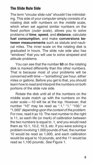
You can see that the number 60 on the rotatingdisk is marked differently than the other numbers.That is because most of your problems will beconcerned with time —“something” per hour, eithermiles or gallons. Before you get to that, you shouldlearn how to read and interpret the numbers on bothportions of the slide rule side.
Rotate the disk until all of the numbers on themiddle scale match up with the numbers on theouter scale —10 will be at the top. However, thatnumber “10” may be read as “.1,” “1,” “100,” or“1,000” depending upon the context of the problem.For now, read it as 10. The next number to the rightis 11, so each life (or mark) of calibration betweenthe two numbers is equal to .1, and you would readthem as 10.1, 10.2, 10.3, etc. If you were solving aproblem involving 1,000 pounds of fuel, the number10 would be read as 1,000, and each calibrationwould be equal to 10 pounds, and the 11 would beread as 1,100 pounds. See Figure 1.

6
Now look at the number 15 on the disk. Between 15and 16 each calibration mark is equal to .2 andwould be read as 15.2, 15.4, etc. If you were solvinga problem with an airspeed of 150 knots, the firstcalibration past 15 (150 in this case) would be 152.The spacing changes again at the number 30,where each calibration becomes .5, and at 60,where each calibration equals 1. Before you read avalue from the disks, be sure you understand whateach line of calibration is equal to.
You will use the slide rule side to establishratios. With the numbers matched, the ratio is 1 to1. Now set the number 60 (the rate arrow) directlyopposite to (or, “lined-up” with) 12 on the outer disk(see Figure 2). Notice that all of the numbers on theouter disk are exactly twice the value of the num-bers on the inner disk: 90 is opposite of 180, 15 isopposite of 30, 3.5 is opposite of 7.0. You will usethese ratios in solving time-speed-distance and fuelconsumption problems.
Look at the inside scale on the disk, where thelines of calibration look like clock times: 9:00, 6:00,etc.—these express hours. The inner scale is inhours and the middle scale is in minutes. 1:10 isdirectly below 70; one hour and ten minutes is thesame as seventy minutes. 5:00 is printed below 300minutes, and five hours is the same as 300 minutes.To convert minutes to seconds, place the rate arrowopposite to the minutes on the outer scale and readseconds opposite to the “seconds” arrow, just to theright of 35 on the inner scale.

7
Figure 2. Line up the number 60 (the rate arrow) withthe number 12 on the outer disk (or, scale).

8
Time, Speed, and Distance Problems
The rate arrow on the disk is always set to indicate avalue per hour on the outer scale. There are threebasic time-speed-distance problems. In two of theseproblems you know the rate, while in the third prob-lem, the rate is part of the answer you are looking for.
To find the Time En Route, let’s assume youknow your airspeed is 150 knots (nautical miles perhour).
1. Set the rate arrow to 150. See Figure 3.2. You have determined the distance to your
destination to be 245 nautical miles. Speedand distance are always on the outer scale;245 is halfway between 24 and 25.
3. Look directly opposite to that value on theinner scale to find the Time En Route. It isbetween 1:35 and 1:40. There are five cali-bration marks on the middle scale between1:35 and 1:40, and 245 NM on the outer scaleis closest to the third calibration, or one hourand 38 minutes.
To find out how far you can go if your fuelendurance is 4.5 hours and your ground speed isknown to be 125 knots:
1. Set the rate arrow at 125 on the outer scale.See Figure 4.
2. Find 4:30 on the inner scale.3. The value on the outer scale is slightly more
than 55. You know that 4 hours at 125 knotsshould cover 500 miles, so the outer scale isread as 500, not 50 or 5,000, which makeseach large calibration mark worth 10 nauticalmiles. The answer is 564 nautical miles.

9
Figure 4
Figure 3
10
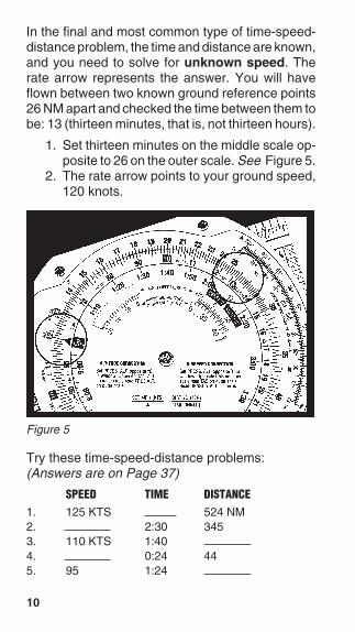
In the final and most common type of time-speed-distance problem, the time and distance are known,and you need to solve for unknown speed. Therate arrow represents the answer. You will haveflown between two known ground reference points26 NM apart and checked the time between them tobe: 13 (thirteen minutes, that is, not thirteen hours).
1. Set thirteen minutes on the middle scale op-posite to 26 on the outer scale. See Figure 5.
2. The rate arrow points to your ground speed,120 knots.
Try these time-speed-distance problems:(Answers are on Page 37)
SPEED TIME DISTANCE1. 125 KTS 524 NM2. 2:30 3453. 110 KTS 1:404. 0:24 445. 95 1:24
Figure 5

11
Fuel Consumption Problems
Problems involving fuel consumption, fuel endur-ance, and fuel capacity are solved using the samenumbers you used in the time-speed-distance prob-lems. With the exception of time values, only thenames change.
Assume that your airplane’s Approved FlightManual indicates fuel consumption of 8.4 gallonsper hour at a given power setting and that the usablefuel capacity is 64 gallons. How many hours endur-ance do you have in the tanks?
1. Line up the rate arrow (“something per hour”)with 8.4 on the outer scale. See Figure 6.
2. Now find 64 on the outer scale.3. Opposite of 64, read fuel endurance in hours:
7:37 on the inner scale. The outer scale,which was used for speed and distance, isnow used to indicate gallons per hour andfuel capacity.
Figure 6

12
When you paid for your fuel you noted on thedelivery ticket that it took 32 gallons to top the tanks.You flew four hours and twenty minutes beforestopping for fuel. What was the average fuel con-sumption? This time the rate arrow provides theanswer.
1. Set 4:20 on the inner scale (or 260 on themiddle scale) opposite of 32 on the outerscale. See Figure 7.
2. The rate arrow indicates the average fuelburn rate: 7.4 gallons per hour.
Remember that fuel consumption is greater duringthe climb to altitude, so this average value does notaccurately reflect fuel consumption in cruising flight.
Figure 7
Try these examples:(Answers are on Page 37)
GALLONS PER HOUR TIME TOTAL USED1. 7.8 3:202. 4:50 623. 8.5 384. 10 2:305. 12 22
13
ConversionsYou can’t solve a problem unless the values agree.You can’t mix statute and nautical miles, gallonsand liters, or Fahrenheit and Celsius. Your ASAE6-B Flight Computer makes it possible for you toconvert between values with simple settings of themiddle scale.
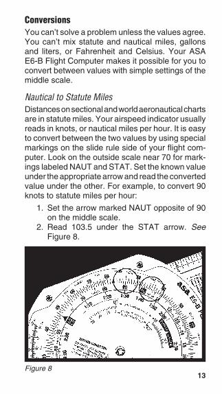
Nautical to Statute MilesDistances on sectional and world aeronautical chartsare in statute miles. Your airspeed indicator usuallyreads in knots, or nautical miles per hour. It is easyto convert between the two values by using specialmarkings on the slide rule side of your flight com-puter. Look on the outside scale near 70 for mark-ings labeled NAUT and STAT. Set the known valueunder the appropriate arrow and read the convertedvalue under the other. For example, to convert 90knots to statute miles per hour:
1. Set the arrow marked NAUT opposite of 90on the middle scale.
2. Read 103.5 under the STAT arrow. SeeFigure 8.
Figure 8

14
You can convert either nautical or statute miles tokilometers. Find the KM marking on the outerscale. Set the known value beneath the NAUT orSTAT arrow as before, and read kilometers underthe KM marking. For example, to convert 115 stat-ute miles to kilometers:
1. Set 115 opposite of the STAT arrow.2. Read 185 under the KM marking.
See Figure 9.
Figure 9
Try these sample problems:(Answers are on Page 37)
NAUT STAT KM1. 202. 483. 110
15
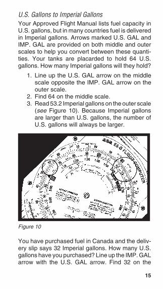
U.S. Gallons to Imperial GallonsYour Approved Flight Manual lists fuel capacity inU.S. gallons, but in many countries fuel is deliveredin Imperial gallons. Arrows marked U.S. GAL andIMP. GAL are provided on both middle and outerscales to help you convert between these quanti-ties. Your tanks are placarded to hold 64 U.S.gallons. How many Imperial gallons will they hold?
1. Line up the U.S. GAL arrow on the middlescale opposite the IMP. GAL arrow on theouter scale.
2. Find 64 on the middle scale.3. Read 53.2 Imperial gallons on the outer scale
(see Figure 10). Because Imperial gallonsare larger than U.S. gallons, the number ofU.S. gallons will always be larger.
Figure 10
You have purchased fuel in Canada and the deliv-ery slip says 32 Imperial gallons. How many U.S.gallons have you purchased? Line up the IMP. GALarrow with the U.S. GAL arrow. Find 32 on the

16
middle scale and read 38.5 U.S. gallons on theouter scale.
Quantity/Weight ConversionsAviation gasoline weighs 6 pounds per U.S. gallon.For weight and balance calculations, aviation gaso-line weight-per-gallon can be determined by liningthe U.S. GAL arrow on the middle scale with theFUEL LBS arrow on the outer scale. Fuel gallonsare read on the middle scale and fuel weight on theouter scale. To find the weight of 32 U.S. gallons:
1. Align the arrows.2. Read 192 pounds on the outer scale opposite of
32 gallons on the middle scale. See Figure 11.
Figure 11
Similarly, oil weight may be determined by lining theU.S. GAL arrow on the middle scale with the OILLBS arrow on the outer scale. Oil gallons are readon the middle scale and oil weight is read on theouter scale. To find the weight of 2 gallons (8 quarts)of oil:

17
1. Align the arrows.2. Read 15 pounds on the outer scale opposite of
2 gallons on the middle scale. See Figure 12.
Imperial gallon weight of fuel and oil may also bedetermined in the same manner by lining up theIMP. GAL arrow on the middle scale with the FUELLBS or OIL LBS arrow on the outer scale.
You can convert liters to U.S. gallons, poundsto kilograms, or feet to meters by aligning theappropriate arrows on the middle and outer scales.For example, to convert pounds to kilograms:
1. Find the arrows marked LBS. and KG, andline them up.
2. Any value in pounds on the outer scale will beopposite of its converted value in kilogramson the middle scale: 2,000 lbs is 901 kg, and160 kg is 351 lbs.
3. The same procedure is followed for the otherconversions.
Figure 12
18
Using the Altitude and SpeedCorrection Windows
Altimeters and airspeed indicators are designed togive correct indications under standard conditionsat sea level. The consistency of the earth’s atmo-sphere does not change linearly as you gain alti-tude; its density is affected by variations in tempera-ture and pressure. The E6-B provides windows onthe slide rule side so you can allow for thesevariations when converting calibrated airspeed totrue airspeed or indicated altitude to true altitude.
True Airspeed and Density Altitude
Note that the outer scale of your flight computer ismarked TAS (true airspeed) and the middle scale ismarked CAS (calibrated airspeed).
The Approved Flight Manual for your airplanecontains a conversion table that allows you toconvert indicated airspeed to CAS. The differenceis greatest at low speeds and becomes negligible atcruise speeds. To determine true airspeed youmust first know the pressure altitude. Set youraltimeter to 29.92 and read the altitude indicated;that is the pressure altitude. Note the outside airtemperature and convert it to Celsius using theconversion scale at the bottom of the flight computer.
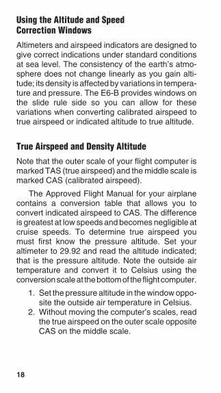
1. Set the pressure altitude in the window oppo-site the outside air temperature in Celsius.
2. Without moving the computer’s scales, readthe true airspeed on the outer scale oppositeCAS on the middle scale.

19
3. Read the density altitude over the arrow inthe DENSITY ALTITUDE window. See Fig-ure 13.
Figure 13 shows a pressure altitude of 15,000 feetset opposite an outside air temperature of -15°C. Acalibrated airspeed of 145 knots converts to a trueairspeed of 183 knots and a density altitude of15,000 feet under these conditions.
Here are some sample problems:(Answers are on Page 37)
PRESSURE DENSITYALTITUDE TEMP CAS TAS ALTITUDE
1. 14,000 5°C 1602. 20,000 -20°C 2003. 8,000 15°C 150
Figure 13

20
Converting Mach Number to True AirspeedTo convert Mach Number to True Airspeed (or viceversa), rotate the inner dial until you see the MachNo. Index inside the airspeed correction window onthe inner dial. Line up the true or outside air tem-perature (do not use Indicated Air Temperature)opposite this Mach No. Index. Mach Number on theinner scale reads opposite True Airspeed (in nauticalmiles per hour) on the outer scale. In Figure 14, at anoutside air temperature of +15°C and Mach 1 (10 onthe inner scale), read 661 knots on the outer scale.
Figure 14

21
True AltitudeWhen the air is colder than standard your altimetercan mislead you into thinking you are higher thanyou actually are. Determine true altitude by thefollowing steps:
1. Determine pressure altitude by setting 29.92momentarily on the altimeter.
2. Set pressure altitude next to outside air tem-perature in the altitude correction window.
3. Subtract station altitude from indicated/cali-brated altitude to determine calibrated alti-tude AGL.
4. Find calibrated altitude AGL on the middlescale and read the correction to station alti-tude on the outer scale.
5. Add the correction to station altitude to gettrue altitude MSL.
Figure 15
22
If the station altitude is unknown, read calibratedaltitude MSL on the middle scale and true altitudeMSL on the outer scale.
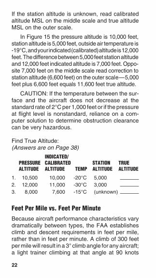
In Figure 15 the pressure altitude is 10,000 feet,station altitude is 5,000 feet, outside air temperature is-19°C, and your indicated (calibrated) altitude is 12,000feet. The difference between 5,000 feet station altitudeand 12,000 feet indicated altitude is 7,000 feet. Oppo-site 7,000 feet on the middle scale read correction tostation altitude (6,600 feet) on the outer scale—5,000feet plus 6,600 feet equals 11,600 feet true altitude.
CAUTION: If the temperature between the sur-face and the aircraft does not decrease at thestandard rate of 2°C per 1,000 feet or if the pressureat flight level is nonstandard, reliance on a com-puter solution to determine obstruction clearancecan be very hazardous.
Find True Altitude:(Answers are on Page 38)
INDICATED/PRESSURE CALIBRATED STATION TRUEALTITUDE ALTITUDE TEMP ALTITUDE ALTITUDE
1. 10,500 10,000 -20°C 5,0002. 12,000 11,000 -30°C 3,0003. 8,000 7,600 -15°C (unknown)
Feet Per Mile vs. Feet Per Minute
Because aircraft performance characteristics varydramatically between types, the FAA establishesclimb and descent requirements in feet per mile,rather than in feet per minute. A climb of 300 feetper mile will result in a 3° climb angle for any aircraft;a light trainer climbing at that angle at 90 knots

23
Figure 16
ground speed will indicate 450 feet per minute,while a jet following that same gradient at 240 knotsground speed will show a vertical speed of 1,200feet per minute.
You can convert feet per mile to feet per minuteby placing the rate arrow opposite to the groundspeed, finding the feet per minute value on the outerscale lined up with the feet per mile value on themiddle scale. Try these two examples:
1. Set the rate arrow opposite of 90.2. Find 300 feet per mile on the middle scale
(see Figure 16).3. The climb rate in feet per minute, 450, is
found on the outer scale opposite of 300.
1. Set the rate arrow at 240 knots.2. Look above 300 on the middle scale.3. You should find a vertical speed of 1,200 feet
per minute.
24
(Answers are on Page 38)
GROUND SPEED FEET PER MILE FEET PERREQUIRED MINUTE
1. 120 3502. 100 2503. 150 300
Off-Course Problems
When you navigate by pilotage, you will occasion-ally find your airplane has drifted off the plannedcourse due to the wind. If you find yourself over alandmark to one side of the course line you shouldbe able to estimate the distance you have drifted offcourse (the scale of sectional charts is 8 statutemiles to the inch), and your flight log should helpdetermine how far you have flown and how far it isto your destination.
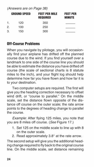
Two computer setups are required. The first willgive you the heading correction necessary to offsetwind drift, or “course to parallel.” On the middlescale, set the distance flown opposite of the dis-tance off course on the outer scale; the rate arrowpoints to the degrees of heading change to parallelthe course.
Example: After flying 125 miles, you note thatyou are 8 miles off course. (See Figure 17.)
1. Set 125 on the middle scale to line up with 8on the outer scale.
2. Read approximately 3.8° at the rate arrow.
The second setup will give you the additional head-ing change required to fly back to the original courseline. On the middle scale, set distance remaining

25
Figure 17
opposite of the distance off course; read additionaldegrees of heading change opposite of the ratearrow. Add the two answers and apply the result toyour heading.
Example: Your destination is 235 miles ahead(see Figure 18 on the next page).
1. Set 235 on the middle scale opposite 8 on theouter scale.
2. Read 2.4° at the rate arrow.3. Change course 6° (3.8 + 2.4) toward the
course line and, if the wind doesn’t change,you will rejoin the original course line as youapproach the destination.
See also Figure 19 on the next page.

26
Figure 19 shows the setups in equations.
Figure 19
Figure 18

27
The Crosswind Table
To determine headwind, tailwind or crosswindcomponent quickly and easily, you must know theangle between your course and the reported winddirection. You also must know the reported windvelocity. This will be especially helpful in anticipat-ing the effect of wind when landing, because windreported by a tower, flight service station, or ATIS issurface wind. These reports give wind direction inrelation to magnetic north and can be compared toyour airplane’s heading indicator without correc-tion. If you use the table with winds aloft, rememberthat those winds are reported in relation to true northand you must apply variation before comparingthem to the heading indicator.
Figure 20

28
Example: The ATIS reports the wind as from230° at 14 knots with runway 18 in use. In thecolumn headed by 50° (see Figure 20) there isa box for 10 knots and a box for 20 knots.Interpolating, the headwind component will be9.5 knots and the crosswind component will be11.5 knots. Those are “approximate” becausethe wind when you touch down will rarely beexactly what was reported.
The Wind Side of the Slide
Directions for use of the wind side are printed on theslide (see Figure 21). It provides a graphic methodof solving problems in trigonometry and displayingthe answers in a very useful form.
To determine ground speed and wind correc-tion angle you must know four things: true course,true airspeed, true wind direction, and wind velocity.The winds aloft forecast provides the latter two; truecourse is measured directly on your sectional orWAC chart, and TAS is either converted from indi-cated airspeed in flight or taken from the airplane’sperformance charts during preflight planning.
Enter the wind first. Rotate the transparent diskuntil the reported wind direction lines up with theTRUE INDEX. Measure up from the grommet andmake a dot equal to the wind velocity. Each lineequals 1 knot on the E6-B, 2 knots on the paper(E6B-P) and micro (E6B-1) models, and 1 or 10knots on the high-speed E6-B slide accessory(E6B-SLIDE).
Now rotate the transparent disk until the truecourse lines up with the TRUE INDEX, and movethe slide up or down until the wind dot falls on the arc
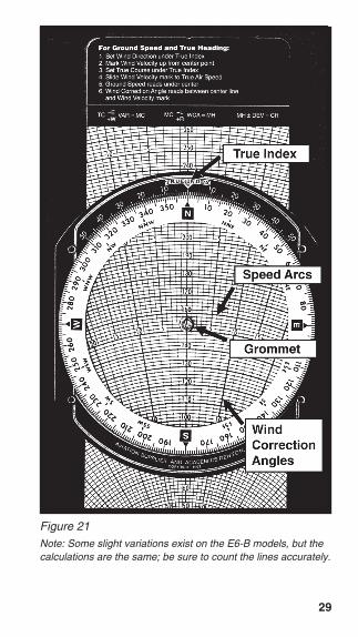
29
TC VAR = MC–E+W MC WCA = MH
–L+R MH ± DEV = CH
Figure 21Note: Some slight variations exist on the E6-B models, but thecalculations are the same; be sure to count the lines accurately.

30
that represents the true airspeed. Read groundspeed under the grommet. The wind correctionangle is measured right or left of the center line. Besure to count the degrees accurately—the value ofeach line changes at the 100, 150, or 250 knot arc,depending on the E6-B model you are using (seeNote below Figure 21).
Example: You have laid out a course on asectional chart and measured it to be 090° trueusing your plotter. The winds aloft forecastcalls for the wind at your chosen altitude to be230° at 18 knots, and the performance data forthe airplane says that you can expect a trueairspeed of 125 knots at that altitude.
1. Set 230° at the TRUE INDEX.2. Using any convenient starting point, mea-
sure 18 units up from the grommet toward theTRUE INDEX and make a dot at 18 units (seeFigure 22).
3. Rotate the transparent disk to bring 090° tothe TRUE INDEX.
4. Move the slide until the wind dot falls on thearc for 125 knots (see Figure 23 on Page 32).
5. Read the ground speed of 138 knots underthe grommet; the fact that the wind dot isbelow the grommet indicates a tailwind.
6. The wind dot is 5° to the right, indicating thatthe true heading should be 095°. Now all youhave to do is apply local magnetic variation toderive magnetic heading.
If the upper winds forecast applies to your entire trip,simply use the wind dot in this manner with the truecourse for each leg.

31
Figure 22
Here are some sample problems:(Answers are on Page 38)
TRUEWIND WIND TRUE TRUE GROUNDDIREC. VELOCITY COURSE TAS HDG SPEED
1. 240 38 300 1652. 040 43 150 1403. 330 25 020 1804. 110 18 260 225

32
Determining Winds in Flight
Winds aloft forecasts are frequently in error. If youhave an autopilot and some free time, you cancalculate the actual winds at your location andaltitude. It helps if you have GPS, too.
To solve an inflight wind problem you need yourground speed, true heading, true course, and trueairspeed. Let’s assume your true course is 180°,your true heading is 160°, your last ground speed
Figure 23

33
check came out to be 120 knots, and you calculatethe true airspeed at your altitude to be 140 knots.
1. Set 180° at the TRUE INDEX on the windside of the computer.
2. Move the slide until the grommet falls overthe line marked 120. The true heading is 20°less than the true course, which means thatyou have a 20° left wind correction angle.
3. With the grommet on the 120-knot groundspeed line, find the point on the slide wherethe 20° left wind correction angle crosses theline marked 140 and make a pencil mark (seeFigure 24 on the next page).
4. Rotate the azimuth disk until the pencil markis on the centerline between the grommetand the true index.
5. Determine the wind velocity by counting thelines between the grommet and the pencilmark.
6. Read the true wind direction under the trueindex. You should have a wind direction of104° and a wind speed of 50 knots (seeFigure 25 on Page 35).
If you have GPS, the direct track readout is usedinstead of true heading. Correct for variation, be-cause the direct track information is magnetic.
Sample problems:(Answers are on Page 38)
TRUE TRUE GROUND WIND WINDHDG COURSE TAS SPEED DIREC. VELOCITY
1. 320 315 140 1282. 175 160 150 115

34
Figure 24

35
Figure 25
36
Notes

37
Answers to Sample Problems
Time-Speed-Distance Problems, Page 10
1. 4 Hours and 12 Minutes
2. 138 Knots
3. 183 Nautical Miles
4. 110 Knots
5. 133 Nautical Miles
Fuel Consumption Problems, Page 12
1. 26 Gallons
2. 12.8 GPH
3. 4 Hours and 28 Minutes
4. 25 Gallons
5. 1 Hour and 50 Minutes
Distance Conversion Problems, Page 14
1. 23 Statute Miles, 37 Kilometers
2. 41.7 Nautical Miles, 77.2 Kilometers
3. 59.4 Nautical Miles, 68.4 Statute Miles
Airspeed Conversion Problems, Page 19
1. 204 Knots TAS, 16,000' DA
2. 273 Knots TAS, 20,500' DA
3. 174 Knots TAS, 9,800' DA
38
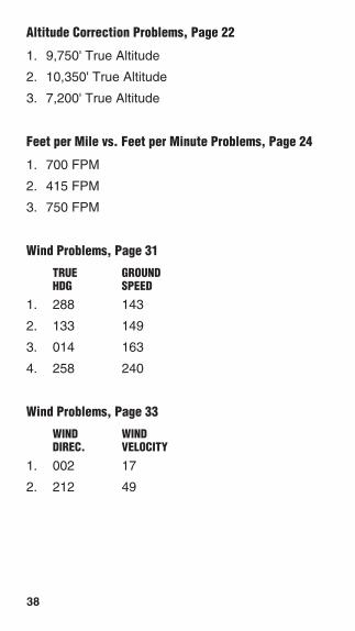
Altitude Correction Problems, Page 22
1. 9,750' True Altitude
2. 10,350' True Altitude
3. 7,200' True Altitude
Feet per Mile vs. Feet per Minute Problems, Page 24
1. 700 FPM
2. 415 FPM
3. 750 FPM
Wind Problems, Page 31
TRUE GROUNDHDG SPEED
1. 288 143
2. 133 149
3. 014 163
4. 258 240
Wind Problems, Page 33
WIND WINDDIREC. VELOCITY
1. 002 17
2. 212 49