
E5BYTQ3
8
IEEE TRANSACTIONS ON ANTENNAS AND PROP AGA TION, VOL. 57, NO. 2, FEBRUARY 2009 331 Broadband Micros tri p Antenna With Left-Handed Metamaterials Merih Pa landoken, Andre Gr ede, and Heino Hen ke Abstract—A novel type of microstrip antenna is proposed for compact wideband wireless applications. The antenna is composed of six unit cells of left-handed metamaterial (LHM) and a dipole element. The dipole is directly connected to three of six LHM unit ce lls , whi ch ar e arranged in a 2 3 ant enn a arr ay f orm. In thi s aspect, the proposed antenna is regarded as LHM loaded dipole antenna. The antenna is matched with a stepped impedance trans- former and rectangular slot in the truncated ground plane. The coupled LH resonances and simultaneous excitation of different sections of unit cells and dipole result into broad bandwidth. The pr oposed an ten na has a maximum gai n of 1 dBi at 2. 5 GHz . The measured return loss indicates 63% bandwidth for over the band of 1.3–2.5 GHz. The overall size of LHM loadedanten na is at thecent er frequency. The radiation of the electrically small LHM unit cells is also demonstrated by the simulated radiation pattern, which is an important concept for the antenna miniaturization. Index Terms—Dipol e anten nas, left- hande d metamater ials (LHMs), loaded antennas, periodic structure. I. INTRODUCTION T HE demand on the portable mobile devices is increasing progr essi vely with the dev elopment of nove l wirel ess communication techniques. In that respect, compact size, light weight, low profile and low cost are now quite important chal- lenges to be accomplished by the designers for every wireless mob ile component. One of the mos t important components of any wirele ss system is its rad iat ing ele ment. In add iti on to the phys ical requireme nts, the emer ging requiremen ts of the wireless systems are high directivity, large gain, efficient and broadband operability of the antennas. Many broadband techniques have been investigated in order to overcome the trade off between the size of the antenna and minimum achiev- abl e qua lit y factor, whi ch is dictated by Chu formula tio ns [1]. These techniques are mainly increasing the thickness of the substrate, using different shaped slots or radiating patches [2]–[4], stacking different radiating elements or loading of the antenna laterally or vertically [5]–[7], utilizing magnetodielec- tric substrates [8] and engineering the ground plane as in the case of EBG metamaterials [9]. Manuscript received January 28, 2008; revise d August 19, 2008. Current ver- sion published March 20, 2009. The authors are with the Technische Universitaet Berlin, 10587 Berlin, Ger- many (e-mail: [email protected]; [email protected]; [email protected]). Color versions of one or more of the figures in this paper are available online at http://ieeexplo re.ieee.org. Digital Object Identifier 10.1109/TAP.2 008.20112 30 Metamaterials are artificially structured materials providing electromagnetic properties not encountered in nature. The elec- trodynamics of hypothetical materials having simultaneously negative permittivity and permeability was first theoretically predicted by Veselago [10]. These materials are termed as “left- han dedmateri als (LHM)” due to the lef t-hand edn ess of ele ctr ic, magne tic fi eld and wavevecto r. There are q uite intere sting elec- tro mag net ic phe nomena rel ate d wit h LHMincluding re ver sal of Doppler effect, reversal of Goos-Hänchen effect, inverse Snells law and reverse Cherenkov radiation [10]. A left-handed material was first implemented in a two di- mensional periodic array of split ring resonators and long wire st rip s by Smit h [11]. Th e lo gi ca l appr oa ch was to exci te the sp lit ring resonators and wire strips in order to force the structure to behave like magnetic and electric dipoles, respectively [12]. Since then, there have been large numbers of experimental in- vestigations on the observation of this phenomenon. The effec- tive electromagnetic parameters were also retrieved experimen- tally and numerically from the transmission and reflection data [15]–[19]. Rather than split ring resonators and wire strips, the left-handed feature can also be realized with periodic loading of conventional microstrip transmission lines with series capac- itors and shunt inductors [12], [20]. Many microwave circuits have been implemented by using this strategy such as com- pact broadband couplers [12], [21], broadband phase shifters [20], compac t wid eba nd filters [22], compact res onatorant enn as [23 ]–[ 26] . In ter ms of tra vel ing wa ve ant enn as, a lea ky wave an- tenna consisting of a microstrip transmission line has also been realized [12], [27]. Because its radiation principle depends on the leakage from the transmission line, this type of antenna has the length comparable to the wavelength. However, this kind of LH leaky wave antenna has a very unique property of back- fire-to-endfire frequency scanning capability with broadside ra- diation, which is not possible for RH leaky wave antennas [12]. Recently, an unsymmetrically fed LH dipole antenna has been demonstrated as an example for an electrically small antenna [28]. In this paper, a b roadba nd p lanar anten na, which is compo sed of a di po le an d six LHM unit ce ll s,is demons tr ated. The an tenna is ma tched to 50 with the s teppe d imp edanc e tra nsformer an d rectangular slot in the truncated ground plane. By the utiliza- tion of phase compensation and coupled resonance feature of LHMs, the narrowband dipole antenna is operated at broader bandwidth. The structure of the electrically small LHM unit cell is de- scribed together with the geometrical parameters. A one dimen- sionaldis per sio n dia gra m is numeri cal ly cal cul ate d by fini te ele - ment method (FEM) in S ectio n II t o pro ve the leftha ndedn ess of the proposed unit cell. The effective permittivity, permeability 0018-926X/$25.00 © 2009 IEEE
-
Upload
killerjackass -
Category
Documents
-
view
215 -
download
0
Transcript of E5BYTQ3

8/13/2019 E5BYTQ3
http://slidepdf.com/reader/full/e5bytq3 1/8
IEEE TRANSACTIONS ON ANTENNAS AND PROPAGATION, VOL. 57, NO. 2, FEBRUARY 2009 331
Broadband Microstrip AntennaWith Left-Handed Metamaterials
Merih Palandoken, Andre Grede, and Heino Henke
Abstract—A novel type of microstrip antenna is proposed forcompact wideband wireless applications. The antenna is composedof six unit cells of left-handed metamaterial (LHM) and a dipoleelement. The dipole is directly connected to three of six LHM unitcells, which are arranged in a 2 3 antenna array form. In thisaspect, the proposed antenna is regarded as LHM loaded dipoleantenna. The antenna is matched with a stepped impedance trans-former and rectangular slot in the truncated ground plane. Thecoupled LH resonances and simultaneous excitation of differentsections of unit cells and dipole result into broad bandwidth. Theproposed antenna has a maximum gain of 1 dBi at 2.5 GHz.The measured return loss indicates 63% bandwidth for
over the band of 1.3–2.5 GHz. The overall size of LHM
loadedantenna is
at thecenterfrequency. The radiation of the electrically small LHM unit cells isalso demonstrated by the simulated radiation pattern, which is animportant concept for the antenna miniaturization.
Index Terms—Dipole antennas, left-handed metamaterials(LHMs), loaded antennas, periodic structure.
I. INTRODUCTION
T
HE demand on the portable mobile devices is increasing
progressively with the development of novel wireless
communication techniques. In that respect, compact size, lightweight, low profile and low cost are now quite important chal-
lenges to be accomplished by the designers for every wireless
mobile component. One of the most important components
of any wireless system is its radiating element. In addition
to the physical requirements, the emerging requirements of
the wireless systems are high directivity, large gain, efficient
and broadband operability of the antennas. Many broadband
techniques have been investigated in order to overcome the
trade off between the size of the antenna and minimum achiev-
able quality factor, which is dictated by Chu formulations
[1]. These techniques are mainly increasing the thickness of
the substrate, using different shaped slots or radiating patches[2]–[4], stacking different radiating elements or loading of the
antenna laterally or vertically [5]–[7], utilizing magnetodielec-
tric substrates [8] and engineering the ground plane as in the
case of EBG metamaterials [9].
Manuscript received January 28, 2008; revised August 19, 2008. Current ver-sion published March 20, 2009.
The authors are with the Technische Universitaet Berlin, 10587 Berlin, Ger-many (e-mail: [email protected]; [email protected];[email protected]).
Color versions of one or more of the figures in this paper are available onlineat http://ieeexplore.ieee.org.
Digital Object Identifier 10.1109/TAP.2008.2011230
Metamaterials are artificially structured materials providing
electromagnetic properties not encountered in nature. The elec-
trodynamics of hypothetical materials having simultaneously
negative permittivity and permeability was first theoretically
predicted by Veselago [10]. These materials are termed as “left-
handed materials (LHM)” due to the left-handedness of electric,
magnetic field and wave vector. There are quite interesting elec-
tromagnetic phenomena related with LHM including reversal of
Doppler effect, reversal of Goos-Hänchen effect, inverse Snells
law and reverse Cherenkov radiation [10].
A left-handed material was first implemented in a two di-
mensional periodic array of split ring resonators and long wirestrips by Smith [11]. The logical approach was to excite the split
ring resonators and wire strips in order to force the structure
to behave like magnetic and electric dipoles, respectively [12].
Since then, there have been large numbers of experimental in-
vestigations on the observation of this phenomenon. The effec-
tive electromagnetic parameters were also retrieved experimen-
tally and numerically from the transmission and reflection data
[15]–[19]. Rather than split ring resonators and wire strips, the
left-handed feature can also be realized with periodic loading
of conventional microstrip transmission lines with series capac-
itors and shunt inductors [12], [20]. Many microwave circuits
have been implemented by using this strategy such as com-pact broadband couplers [12], [21], broadband phase shifters
[20], compact wideband filters [22], compact resonator antennas
[23]–[26]. In terms of traveling wave antennas, a leaky wave an-
tenna consisting of a microstrip transmission line has also been
realized [12], [27]. Because its radiation principle depends on
the leakage from the transmission line, this type of antenna has
the length comparable to the wavelength. However, this kind
of LH leaky wave antenna has a very unique property of back-
fire-to-endfire frequency scanning capability with broadside ra-
diation, which is not possible for RH leaky wave antennas [12].
Recently, an unsymmetrically fed LH dipole antenna has been
demonstrated as an example for an electrically small antenna
[28].In this paper, a broadband planar antenna, which is composed
of a dipole and six LHM unit cells, is demonstrated. The antenna
is matched to 50 with the stepped impedance transformer and
rectangular slot in the truncated ground plane. By the utiliza-
tion of phase compensation and coupled resonance feature of
LHMs, the narrowband dipole antenna is operated at broader
bandwidth.
The structure of the electrically small LHM unit cell is de-
scribed together with the geometrical parameters. A one dimen-
sional dispersion diagram is numerically calculated by finite ele-
ment method (FEM) in Section II to prove the lefthandedness of
the proposed unit cell. The effective permittivity, permeability
0018-926X/$25.00 © 2009 IEEE
8/13/2019 E5BYTQ3
http://slidepdf.com/reader/full/e5bytq3 2/8
332 IEEE TRANSACTIONS ON ANTENNAS AND PROPAGATION, VOL. 57, NO. 2, FEBRUARY 2009
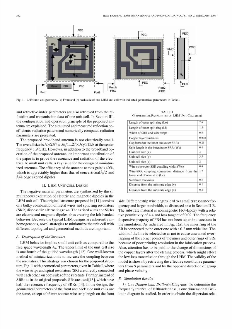
Fig. 1. LHM unit cell geometry. (a) Front and (b) back side of one LHM unit cell with indicated geometrical parameters in Table I.
and refractive index parameters are also retrieved from the re-
flection and transmission data of one unit cell. In Section III,the configuration and operation principle of the proposed an-
tenna are explained. The simulated and measured reflection co-
efficients, radiation pattern and numerically computed radiation
parameters are presented.
The proposed broadband antenna is not electrically small.
The overall size is at the center
frequency 1.9 GHz. However, in addition to the broadband op-
eration of the proposed antenna, an important contribution of
the paper is to prove the resonance and radiation of the elec-
trically small unit cells, a key issue for the design of miniatur-
ized antennas. The efficiency of the antenna at max gain is 40%,
which is appreciably higher than that of conventional andedge excited dipoles.
II. LHM UNIT CELL DESIGN
The negative material parameters are synthesized by the si-
multaneous excitation of electric and magnetic dipoles in the
LHM unit cell. The original structure proposed in [11] consists
of a bulky combination of metal wires and split ring resonators
(SRR) disposed in alternating rows. The excited wires and SRRs
are electric and magnetic dipoles, thus creating the left-handed
behavior. Because the typical LHM designs are inherently in-
homogeneous, novel strategies to miniaturize the unit cell with
different topological and geometrical methods are important. A. Description of the Structure
LHM behavior implies small unit cells as compared to the
free space wavelength . The upper limit of the unit cell size
is one fourth of the guided wavelength [12]. One well-known
method of miniaturization is to increase the coupling between
the resonators. This strategy was chosen for the proposed struc-
ture, Fig. 1 with geometrical parameters given in Table I, where
the wire strips and spiral resonators (SR) are directly connected
with each other, on both sides of the substrate. Further,instead of
SRRs as in the original proposals, SRs are used [13], which have
half the resonance frequency of SRRs [14]. In the design, the
geometrical parameters of the front and back side unit cells arethe same, except a 0.6 mm shorter wire strip length on the front
TABLE I
GEOMETRICAL PARAMETERS OF LHM UNIT CELL (mm)
side. Different strip wire lengths lead to a smaller resonance fre-
quency and larger bandwidth, as discussed next in Section II-B.
The substrate material is nonmagnetic FR4-Epoxy with a rela-
tive permittivity of 4.4 and loss tangent of 0.02. The frequency
dispersive property of FR4 has not been taken into account in
the simulation. As indicated in Fig. 1(a), the inner ring of the
SR is connected to the outer one with a 0.2 mm wide line. Thewidth of the line is selected so as not to cause unwanted over-
lapping of the corner points of the inner and outer rings of SRs
because of poor printing resolution in the fabrication process.
Also, attention has to be paid to the change of dimensions of
the copper layers after the etching process, which might effect
the low loss transmission through the LHM. The validity of the
model is shown by retrieving the effective constitutive parame-
ters from S parameters and by the opposite direction of group
and phase velocity.
B. Simulation Results
1) One Dimensional Brillouin Diagram: To determine the
frequency interval of lefthandedness, a one dimensional Bril-louin diagram is studied. In order to obtain the dispersion rela-
8/13/2019 E5BYTQ3
http://slidepdf.com/reader/full/e5bytq3 3/8
PALANDOKEN et al.: BROADBAND MICROSTRIP ANTENNA WITH LHM 333
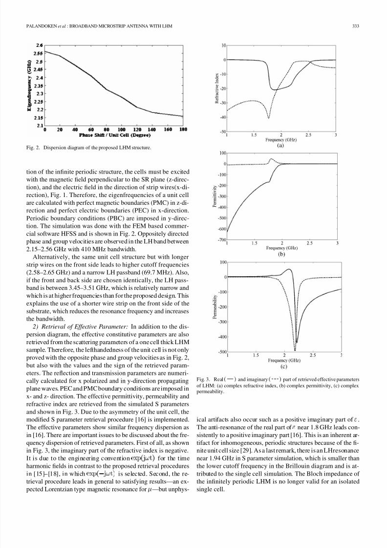
Fig. 2. Dispersion diagram of the proposed LHM structure.
tion of the infinite periodic structure, the cells must be excited
with the magnetic field perpendicular to the SR plane (z-direc-
tion), and the electric field in the direction of strip wires(x-di-
rection), Fig. 1. Therefore, the eigenfrequencies of a unit cell
are calculated with perfect magnetic boundaries (PMC) in z-di-
rection and perfect electric boundaries (PEC) in x-direction.
Periodic boundary conditions (PBC) are imposed in y-direc-
tion. The simulation was done with the FEM based commer-
cial software HFSS and is shown in Fig. 2. Oppositely directed
phase and group velocities are observed in the LH band between
2.15–2.56 GHz with 410 MHz bandwidth.
Alternatively, the same unit cell structure but with longer
strip wires on the front side leads to higher cutoff frequencies
(2.58–2.65 GHz) and a narrow LH passband (69.7 MHz). Also,
if the front and back side are chosen identically, the LH pass-
band is between 3.45–3.51 GHz, which is relatively narrow andwhich is at higher frequencies than for the proposed design. This
explains the use of a shorter wire strip on the front side of the
substrate, which reduces the resonance frequency and increases
the bandwidth.
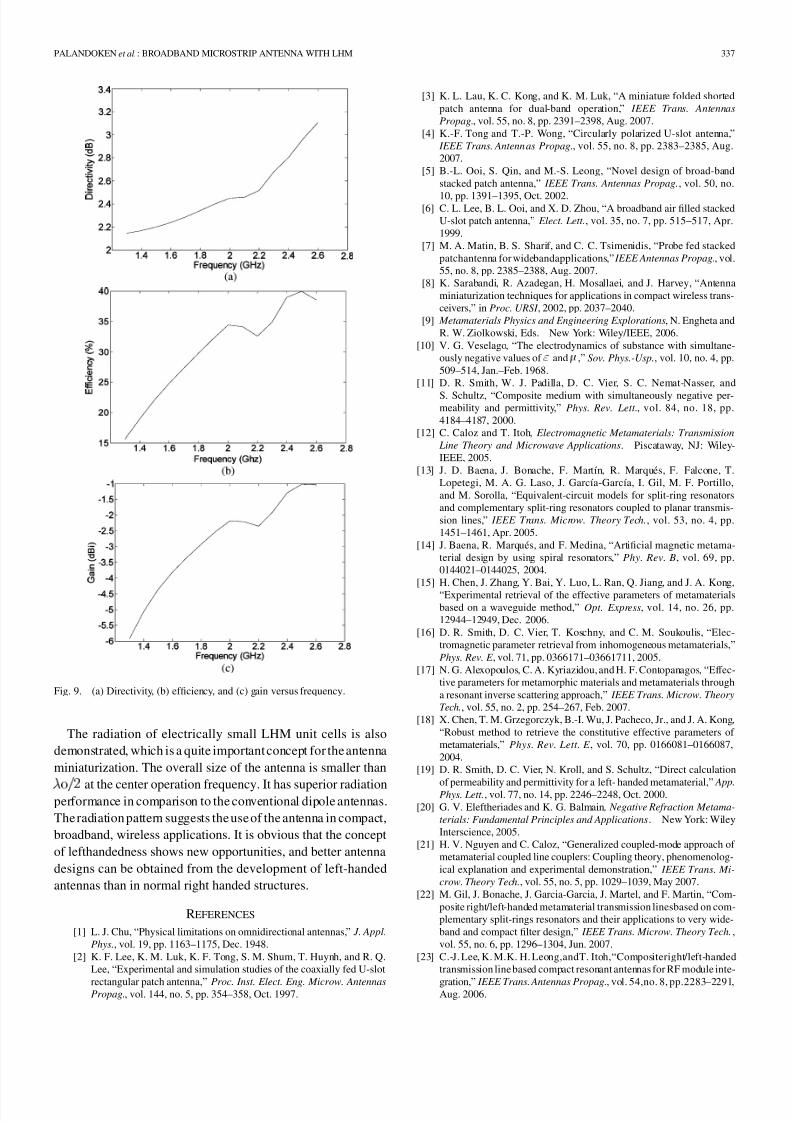
2) Retrieval of Effective Parameter: In addition to the dis-
persion diagram, the effective constitutive parameters are also
retrieved from the scattering parameters of a one cell thick LHM
sample. Therefore, the lefthandedness of the unit cell is not only
proved with the opposite phase and group velocities as in Fig. 2,
but also with the values and the sign of the retrieved param-
eters. The reflection and transmission parameters are numeri-
cally calculated for x polarized and in y-direction propagatingplane waves. PEC and PMC boundary conditions are imposed in
x- and z- direction. The effective permittivity, permeability and
refractive index are retrieved from the simulated S parameters
and shown in Fig. 3. Due to the asymmetry of the unit cell, the
modified S parameter retrieval procedure [16] is implemented.
The effective parameters show similar frequency dispersion as
in [16]. There are important issues to be discussed about the fre-
quency dispersion of retrieved parameters. First of all, as shown
in Fig. 3, the imaginary part of the refractive index is negative.
It is due to the engineering convention for the time
harmonic fields in contrast to the proposed retrieval procedures
in [15]–[18], in which is selected. Second, the re-
trieval procedure leads in general to satisfying results—an ex-pected Lorentzian type magnetic resonance for —but unphys-
Fig. 3. Real and imaginary
part of retrieved effective parameters
of LHM: (a) complex refractive index, (b) complex permittivity, (c) complexpermeability.
ical artifacts also occur such as a positive imaginary part of .
The anti-resonance of the real part of near 1.8 GHz leads con-
sistently to a positive imaginary part [16]. This is an inherent ar-
tifact for inhomogeneous, periodic structures because of the fi-
nite unit cell size [29]. As a last remark, there is an LHresonance
near 1.94 GHz in S parameter simulation, which is smaller than
the lower cutoff frequency in the Brillouin diagram and is at-
tributed to the single cell simulation. The Bloch impedance of
the infinitely periodic LHM is no longer valid for an isolatedsingle cell.

8/13/2019 E5BYTQ3
http://slidepdf.com/reader/full/e5bytq3 4/8
334 IEEE TRANSACTIONS ON ANTENNAS AND PROPAGATION, VOL. 57, NO. 2, FEBRUARY 2009
Fig. 4. Surface eigencurrent distribution on the (a) front and (b) back side of one unit cell.
The LH band for retrieved parameters extends from 1.75 up
to 2.55 GHz. It is in good correspondence with simulated band
in the range from 2.17–2.53 GHz in terms of refractive indicies
calculated directly from the dispersion diagram in Fig. 2 [29].
The size of a unit cell is approximately 1/43 of at 2 GHz,
which is directly connected, in first approximation and ne-
glecting all coupling, to the total metallic length from the
open circuited SR to the short circuited wire strip. The varying
degree of coupling between the resonators shifts and broadens
the transmission band. If the electrically small unit cells are
excited by their eigencurrents, they represent effective radiating
elements and are key elements for the future aspects in the
antenna miniaturization.
III. ANTENNA DESIGN
A. Operation Principle
The operation principle of the antenna depends on the radia-
tion of the dipole antenna and the excitation of LHM unit cells
with the dipole field. The excitation of LH cells in their eigen-
modes causes the individual electric and magnetic dipoles to be
coupled in the same way as in the eigenmode simulation. These
unit cell dipoles are also radiation sources in addition to the ex-
citing dipole antenna even though they are designed as loads for
the dipole. The magnetic and electric dipole moments are ex-
pressed by the surface current density as in [30]
(1)
(2)
where is the displacement vector directed from the surface
current element to calculation point; is the current
element position; is the differential current carrying surface
element.
The current distribution in one unit cell is inhomogeneous as
shown in Fig. 4. For each unit cell, the electric and magnetic
dipoles are simultaneously excited in principle. However, the
magnetic dipoles are more effective than the electric ones. At
first, magnetic dipole fields do not cancel in the far field be-cause of inplane electrical coupling among the cells on the front
Fig. 5. (a)Top, (b)bottom geometry, and(c) prototypeof theproposed antenna.
and back side as in the case of same direction imaging of the
horizontal magnetic dipole on perfect electric plane. However,
electric dipoles tangential to the electric coupling plane are ac-
tually suppressed as in the case of reverse direction imaging of
horizontal electric dipole over perfect electric plane. The second
reason is that the current on the back side strip wire has partially
opposite directions and do not to excite the electric dipole as ef-
fectively as the magnetic dipole. As a last reason, the surface
current on the back side unit cell spirals in the same direction
as the surface current on the front side unit cell, thus enhancing
the effective magnetic dipole moment. In that respect, front and
back side unit cells are mainly magnetically coupled and the
back side unit cells can be considered as the artificial magnetic
ground plane for the front side unit cells. It also follows from
the Lorentzian type magnetic resonance in Fig. 3(c), which is
the dominating resonance in the retrieved effective parameters.However, the antenna radiates mainly in the dipole mode, which
is the reason why we call it as an LHM loaded dipole antenna.
B. Antenna Design
As a first step in the antenna design, the front and back side
unit cells were connected symmetrically with adjacent cells
in x-direction and periodically in the y-direction, see Fig. 1.
These requirements follow from the boundary condition in the
eigenmode simulation. Six unit cells were used without vertical
stacking and arranged in a 2 3 array, Fig. 5. As can be seen
from the figure, the front sides of unit cells are directly con-
nected to the dipole in order to increase the coupling from thedipole to the LH load. In that way, the impedance of the LH load

8/13/2019 E5BYTQ3
http://slidepdf.com/reader/full/e5bytq3 5/8
PALANDOKEN et al.: BROADBAND MICROSTRIP ANTENNA WITH LHM 335
TABLE IIGEOMETRICAL PARAMETERS OF ANTENNA (mm)
Fig. 6. Measured (solid line) and simulated (dashed line) reflection coefficientof the proposed antenna.
is transformed by the dipole. The truncated ground plane leadsto a decreased stored energy because of lower field components
near the metallic interfaces (decreased effective permittivity).
A rectangular slot in the truncated ground plane allows for one
more degree of freedom for the matching network. The effect
of the slot can be modeled by a shunt element consisting of a
parallel LC resonator in series with the capacitance [22]. The
width of the slot is appreciably smaller than half a wavelength
in the substrate and is optimized together with the length. Geo-
metrical parameters are tabulated in Table II and a prototype is
shown in Fig. 5. All the design parameters have been optimized
for best return loss.
C. Experimental and Simulation Results
The reflection coefficient of the antenna was measured with
the vector network analyzer HP 8722C and is shown in Fig. 6
together with the simulation result. As can be seen from the
data, the bandwidth of 63.16% extends from approximately
1.3–2.5 GHz with the center frequency of 1.9 GHz. Unit cell
resonances can be clearly observed in the passband. The low
frequency ripples are attributed to the inaccurate modeling of
the coax-microstrip line transition. In summary, the measured
and simulated reflection coefficients are in good agreement.
There are nevertheless some issues to be discussed from themeasured and simulated results. First of all, in the experimental
Fig. 7. The footpoint impedance of LHM loaded dipole antenna (top line: sus-ceptance, bottom line: resistance).
TABLE IIIOVERALL SIZE AND RADIATION PARAMETERS OF CONVENTIONAL AND
LHM LOADED DIPOLE ANTENNAS
result, there are lower resonance frequencies than those of the
LH passband in Fig. 2, which is also the case in the simulated re-
flection coefficient. These lower resonance frequencies are due
to the direct coupling between the dipole antenna and LHM unit
cells and are not emerging from the LHM resonances. In order
to prove this reasoning, the current distribution in LHM unit
cells and dipole is examined. At 1.7 GHz, the dipole is stronger
excited than the LHM unit cells, which is obvious because of
out-of.-band resonance. In other words, the LH load impedance
is transformed by the dipole to match at this lower frequency.
Secondly, the bandwidth is enhanced by the fact that different
sections of the LHM cells and the dipole are excited at differentfrequencies. Still, the effect of the LH load is quite important
for broadband operation. In order to figure out the unique prop-
erty for broadbandness, the foot-point impedance of LH loaded
antenna is plotted in Fig. 7. The unit cell resonances are closer
to each other at the lower frequencies than at higher frequen-
cies. This unique property results in a broadband behavior at low
frequencies, which is not the case for RH operation. The same
reasoning can also be deduced from the dispersion diagram in
Fig. 2. Therefore, the coupled resonance feature of LHM unit
cells results in an antenna input impedance as smooth as in the
case of tapering. It is the main reason why the antenna is broad-
band [31], [32]. The topology of matching network is as impor-tant as the broadband load for the wideband operation [33].

8/13/2019 E5BYTQ3
http://slidepdf.com/reader/full/e5bytq3 6/8
336 IEEE TRANSACTIONS ON ANTENNAS AND PROPAGATION, VOL. 57, NO. 2, FEBRUARY 2009
(a) (b)
(c) (d)
Fig. 8. Normalized radiation patterns cross-polarization (o - light line) and co-polarization (+ - dark line) at 1.7 GHz in (a) y-z and (c) x-z plane, and at 2.3 GHzin (b) y-z and (d) x-z plane.
The third important issue is the radiation of electrically small
LHM cells. It could be verified not only from the current dis-
tribution and the return loss but also from the radiation pattern,
which is explained next. To prove the subwavelength radiation,
we simulated also a stub matched antenna with an electrically
very short feeding line and LHM unit cells, and confirmed the
radiation However, we do not include the results due to lim-
ited space. The antenna matching can be explained by the phasecompensation feature of LHM as for instance in the case for the
length independent subwavelength resonators [9] and antennas
[34].
The normalized radiation patterns of the antenna in the y-z
and x-z planes at 1.7 GHz and 2.3 GHz are shown in Fig. 8.
They are mainly dipole-like radiation patterns in E and H planes,
which is the reason to call the antenna an LHM loaded dipole
antenna. The radiation of the electrically small LHM unit cells
is also observed from the radiation pattern at 2.3 GHz. As it is
shown in Fig. 8(b), the more effective excitation of the LHM
cells at 2.3 GHz than at 1.7 GHz results in an asymmetric radi-
ation pattern because of the structure asymmetry along y axis.The cross polarization in the y-z plane is 8 dB higher at 2.3 GHz
than that at 1.7 GHz, see Fig. 2, because of LH passband res-
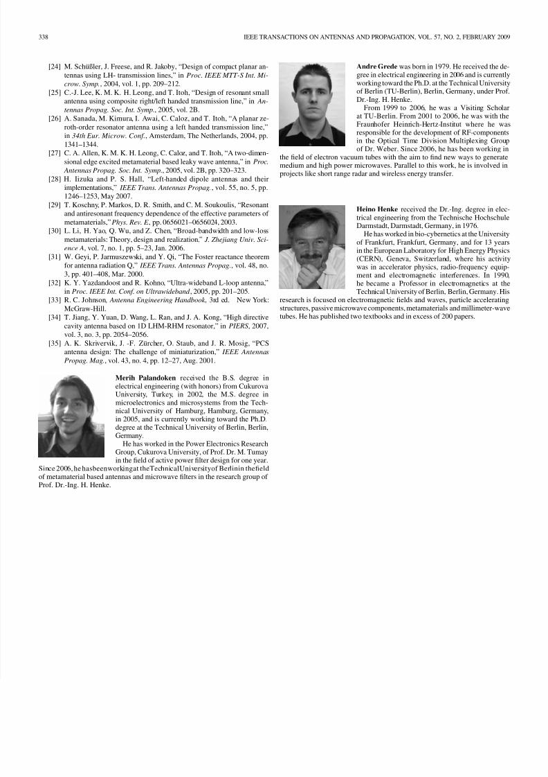
onance. The gain of the broadband antenna is unfortunately
small. The maximum gain and directivity are 1 dBi and 3 dB
with 40% efficiency at 2.5 GHz, respectively. The gain, direc-
tivity and efficiency are plotted in Fig. 9. For the comparison of
the overall size and radiation parameters of the proposed design
with the conventional dipole antennas, two edge excited and
dipole antennas are designed. The simulated antenna pa-rameters are tabulated in Table III. The proposed antenna has
relatively better radiation performance than the conventional
dipole antennas. In addition, the gain of proposed antenna is
higher than different kinds of miniaturized and narrow band an-
tennas in literature [23], [25], [28], [35].
IV. CONCLUSION
A broadband planar antenna is proposed by loading a narrow-
band dipole antenna with six LHM unit cells. The antenna pos-
sesses broad impedance bandwidth of 63% overthe band of 1.3–2.5 GHz.
8/13/2019 E5BYTQ3
http://slidepdf.com/reader/full/e5bytq3 7/8
PALANDOKEN et al.: BROADBAND MICROSTRIP ANTENNA WITH LHM 337
Fig. 9. (a) Directivity, (b) efficiency, and (c) gain versus frequency.
The radiation of electrically small LHM unit cells is also
demonstrated, which is a quite important concept for the antenna
miniaturization. The overall size of the antenna is smaller than
at the center operation frequency. It has superior radiationperformance in comparison to the conventional dipole antennas.
The radiation pattern suggests the use of the antenna in compact,
broadband, wireless applications. It is obvious that the concept
of lefthandedness shows new opportunities, and better antenna
designs can be obtained from the development of left-handed
antennas than in normal right handed structures.
REFERENCES
[1] L. J. Chu, “Physical limitations on omnidirectional antennas,” J. Appl.
Phys., vol. 19, pp. 1163–1175, Dec. 1948.[2] K. F. Lee, K. M. Luk, K. F. Tong, S. M. Shum, T. Huynh, and R. Q.
Lee, “Experimental and simulation studies of the coaxially fed U-slot
rectangular patch antenna,” Proc. Inst. Elect. Eng. Microw. AntennasPropag., vol. 144, no. 5, pp. 354–358, Oct. 1997.
[3] K. L. Lau, K. C. Kong, and K. M. Luk, “A miniature folded shortedpatch antenna for dual-band operation,” IEEE Trans. Antennas
Propag., vol. 55, no. 8, pp. 2391–2398, Aug. 2007.[4] K.-F. Tong and T.-P. Wong, “Circularly polarized U-slot antenna,”
IEEE Trans. Antenn as Propag., vol. 55, no. 8, pp. 2383–2385, Aug.2007.
[5] B.-L. Ooi, S. Qin, and M.-S. Leong, “Novel design of broad-bandstacked patch antenna,” IEEE Trans. Antennas Propag., vol. 50, no.
10, pp. 1391–1395, Oct. 2002.[6] C. L. Lee, B. L. Ooi, and X. D. Zhou, “A broadband air filled stacked
U-slot patch antenna,” Elect. Lett., vol. 35, no. 7, pp. 515–517, Apr.1999.
[7] M. A. Matin, B. S. Sharif, and C. C. Tsimenidis, “Probe fed stackedpatchantenna for widebandapplications,” IEEE Antennas Propag., vol.55, no. 8, pp. 2385–2388, Aug. 2007.
[8] K. Sarabandi, R. Azadegan, H. Mosallaei, and J. Harvey, “Antennaminiaturization techniques for applications in compact wireless trans-ceivers,” in Proc. URSI , 2002, pp. 2037–2040.
[9] Metamaterials Physics and Engineering Explorations, N. Engheta andR. W. Ziolkowski, Eds. New York: Wiley/IEEE, 2006.
[10] V. G. Veselago, “The electrodynamics of substance with simultane-ously negative values of and ,” Sov. Phys.-Usp., vol. 10, no. 4, pp.509–514, Jan.–Feb. 1968.
[11] D. R. Smith, W. J. Padilla, D. C. Vier, S. C. Nemat-Nasser, and
S. Schultz, “Composite medium with simultaneously negative per-meability and permittivity,” Phys. Rev. Lett., vol. 84, no. 18, pp.4184–4187, 2000.
[12] C. Caloz and T. Itoh , Electromagnetic Metamaterials: Transmission
Line Theory and Microwave Applications. Piscataway, NJ: Wiley-IEEE, 2005.
[13] J. D. Baena, J. Bonache, F. Martín, R. Marqués, F. Falcone, T.Lopetegi, M. A. G. Laso, J. García-García, I. Gil, M. F. Portillo,and M. Sorolla, “Equivalent-circuit models for split-ring resonatorsand complementary split-ring resonators coupled to planar transmis-sion lines,” IEEE Trans. Microw. Theory Tech., vol. 53, no. 4, pp.1451–1461, Apr. 2005.
[14] J. Baena, R. Marqués, and F. Medina, “Artificial magnetic metama-terial design by using spiral resonators,” Phy. Rev. B, vol. 69, pp.0144021–0144025, 2004.
[15] H. Chen, J. Zhang, Y. Bai, Y. Luo, L. Ran, Q. Jiang, and J. A. Kong,“Experimental retrieval of the effective parameters of metamaterialsbased on a waveguide method,” Opt. Express, vol. 14, no. 26, pp.12944–12949, Dec. 2006.
[16] D. R. Smith, D. C. Vier, T. Koschny, and C. M. Soukoulis, “Elec-tromagnetic parameter retrieval from inhomogeneous metamaterials,”Phys. Rev. E , vol. 71, pp. 0366171–03661711, 2005.
[17] N. G. Alexopoulos, C. A. Kyriazidou, and H. F. Contopanagos, “Effec-tive parameters for metamorphic materials and metamaterials througha resonant inverse scattering approach,” IEEE Trans. Microw. Theory
Tech., vol. 55, no. 2, pp. 254–267, Feb. 2007.[18] X. Chen, T. M. Grzegorczyk, B.-I. Wu, J. Pacheco, Jr., and J. A. Kong,
“Robust method to retrieve the constitutive effective parameters of metamaterials,” Phys. Rev. Lett. E , vol. 70, pp. 0166081–0166087,2004.
[19] D. R. Smith, D. C. Vier, N. Kroll, and S. Schultz, “Direct calculation
of permeability and permittivity for a left- handed metamaterial,” App.Phys. Lett., vol. 77, no. 14, pp. 2246–2248, Oct. 2000.
[20] G. V. Eleftheriades and K. G. Balmain , Negative Refraction Metama-
terials: Fundamental Principles and Applications. New York: WileyInterscience, 2005.
[21] H. V. Nguyen and C. Caloz, “Generalized coupled-mode approach of metamaterial coupled line couplers: Coupling theory, phenomenolog-ical explanation and experimental demonstration,” IEEE Trans. Mi-
crow. Theory Tech., vol. 55, no. 5, pp. 1029–1039, May 2007.[22] M. Gil, J. Bonache, J. Garcia-Garcia, J. Martel, and F. Martin, “Com-
posite right/left-handed metamaterial transmission linesbased on com-plementary split-rings resonators and their applications to very wide-band and compact filter design,” IEEE Trans. Microw. Theory Tech.,vol. 55, no. 6, pp. 1296–1304, Jun. 2007.
[23] C.-J. Lee, K. M.K. H. Leong,andT. Itoh,“Compositeright/left-handedtransmission line based compact resonant antennas for RF module inte-
gration,” IEEE Trans. Antennas Propag., vol. 54,no. 8, pp.2283–2291,Aug. 2006.
8/13/2019 E5BYTQ3
http://slidepdf.com/reader/full/e5bytq3 8/8
338 IEEE TRANSACTIONS ON ANTENNAS AND PROPAGATION, VOL. 57, NO. 2, FEBRUARY 2009
[24] M. Schüßler, J. Freese, and R. Jakoby, “Design of compact planar an-tennas using LH- transmission lines,” in Proc. IEEE MTT-S Int. Mi-
crow. Symp., 2004, vol. 1, pp. 209–212.[25] C.-J. Lee, K. M. K. H. Leong, and T. Itoh, “Design of resonant small
antenna using composite right/left handed transmission line,” in An-
tennas Propag. Soc. Int. Symp., 2005, vol. 2B.[26] A. Sanada, M. Kimura, I. Awai, C. Caloz, and T. Itoh, “A planar ze-
roth-order resonator antenna using a left handed transmission line,”
in 34th Eur. Microw. Conf., Amsterdam, The Netherlands, 2004, pp.1341–1344.
[27] C. A. Allen, K. M. K. H. Leong, C. Caloz, and T. Itoh, “A two-dimen-sional edge excited metamaterial based leaky wave antenna,” in Proc.
Antennas Propag. Soc. Int. Symp., 2005, vol. 2B, pp. 320–323.[28] H. Iizuka and P. S. Hall, “Left-handed dipole antennas and their
implementations,” IEEE Trans. Antennas Propag., vol. 55, no. 5, pp.1246–1253, May 2007.
[29] T. Koschny, P. Markos, D. R. Smith, and C. M. Soukoulis, “Resonantand antiresonant frequency dependence of the effective parameters of metamaterials,” Phys. Rev. E , pp. 0656021–0656024, 2003.
[30] L. Li, H. Yao, Q. Wu, and Z. Chen, “Broad-bandwidth and low-lossmetamaterials: Theory, design and realization,” J. Zhejiang Univ. Sci-
ence A, vol. 7, no. 1, pp. 5–23, Jan. 2006.[31] W. Geyi, P. Jarmuszewski, and Y. Qi, “The Foster reactance theorem
for antenna radiation Q,” IEEE Trans. Antennas Propag., vol. 48, no.
3, pp. 401–408, Mar. 2000.[32] K. Y. Yazdandoost and R. Kohno, “Ultra-wideband L-loop antenna,”
in Proc. IEEE Int. Conf. on Ultrawideband , 2005, pp. 201–205.[33] R. C. Johnson , Antenna Engineering Handbook , 3rd ed. New York:
McGraw-Hill.[34] T. Jiang, Y. Yuan, D. Wang, L. Ran, and J. A. Kong, “High directive
cavity antenna based on 1D LHM-RHM resonator,” in PIERS , 2007,vol. 3, no. 3, pp. 2054–2056.
[35] A. K. Skrivervik, J. -F. Zürcher, O. Staub, and J. R. Mosig, “PCSantenna design: The challenge of miniaturization,” IEEE Antennas
Propag. Mag., vol. 43, no. 4, pp. 12–27, Aug. 2001.
Merih Palandoken received the B.S. degree inelectrical engineering (with honors) from CukurovaUniversity, Turkey, in 2002, the M.S. degree inmicroelectronics and microsystems from the Tech-
nical University of Hamburg, Hamburg, Germany,in 2005, and is currently working toward the Ph.D.degree at the Technical University of Berlin, Berlin,Germany.
He has worked in the Power Electronics ResearchGroup, Cukurova University, of Prof. Dr. M. Tumayin the field of active power filter design for one year.
Since 2006, he hasbeenworkingat theTechnicalUniversityof Berlinin thefieldof metamaterial based antennas and microwave filters in the research group of Prof. Dr.-Ing. H. Henke.
Andre Grede was born in 1979. He received the de-gree in electrical engineering in 2006 and is currentlyworking toward the Ph.D. at the Technical Universityof Berlin (TU-Berlin), Berlin, Germany, under Prof.Dr.-Ing. H. Henke.
From 1999 to 2006, he was a Visiting Scholarat TU-Berlin. From 2001 to 2006, he was with theFraunhofer Heinrich-Hertz-Institut where he was
responsible for the development of RF-componentsin the Optical Time Division Multiplexing Groupof Dr. Weber. Since 2006, he has been working in
the field of electron vacuum tubes with the aim to find new ways to generatemedium and high power microwaves. Parallel to this work, he is involved inprojects like short range radar and wireless energy transfer.
Heino Henke received the Dr.-Ing. degree in elec-trical engineering from the Technische HochschuleDarmstadt, Darmstadt, Germany, in 1976.
He has worked in bio-cybernetics at the Universityof Frankfurt, Frankfurt, Germany, and for 13 yearsin the European Laboratory for High Energy Physics(CERN), Geneva, Switzerland, where his activitywas in accelerator physics, radio-frequency equip-ment and electromagnetic interferences. In 1990,he became a Professor in electromagnetics at theTechnical University of Berlin, Berlin, Germany. His
research is focused on electromagnetic fields and waves, particle acceleratingstructures, passive microwave components, metamaterials and millimeter-wavetubes. He has published two textbooks and in excess of 200 papers.


