E3xA, E3xB, E3xC, E3xE
21
ZL0140-0C Page 1 of 21 ©2017 Veris Industries USA 800.354.8556 or +1.503.598.4564 / [email protected] 0717 Alta Labs, Enercept, Enspector, Hawkeye, Trustat, Aerospond, Veris, and the Veris ‘V’ logo are trademarks or registered trademarks of Veris Industries, L.L.C. in the USA and/or other countries. Other companies’ trademarks are hereby acknowledged to belong to their respective owners. TM Commissioning Guide Power Monitoring Overview This guide is intended to help the user commission the E30 or E31 Panelboard Monitoring System or the E34 Series Multi-Circuit Meter for operation. It is assumed that the user has already installed the E3x meter according to the instructions in the corresponding installation guide. E3xA, E3xB, E3xC, E3xE Guide to Using the NetConfig Tool E30 E31 E34E E34A E30E & E31E Installing the Configuration Tool NetConfig is a PC-based application that allows you to configure the E3x branch circuit power meter. It can communicate with the meter via Modbus TCP over Ethernet (most common) or by Modbus serial. All of the setup parameters can be accessed individually as data elements via Modbus, BACnet, or SNMP, if supported, but the configuration tool provides a simplified user interface. The E3xE models have operating modes that support BACnet or SNMP protocols, but the NetConfig tool uses Modbus protocol that works in any of these operating modes. This commissioning guide is for use with V2.2.1.0 or newer of the NetConfig tool. 1. Copy the NetConfig.zip file provided to your PC. Open this folder, then open the executable file, setup.exe. 2. The NetConfig welcome window appears. Click Next. Table of Contents Installing the Configuration Tool 1 Using the Tool: Locating the Meter(s) 3 Using the Tool: Accessing the Meter(s) 6 Using the Tool: Configuring the Main/Configuration Panel(s) 7 Using the Tool: Configuring the Logical Meters within a Panel 15 Using the Tool: Configuring Logical Meters at Separate Modbus Addresses 18 Copying Settings from One Unit to Another 21 HAZARD OF ELECTRIC SHOCK, EXPLOSION, OR ARC FLASH • Follow safe electrical work practices. See NFPA 70E in the USA, or applicable local codes. • This equipment must only be installed and serviced by qualified electrical personnel. • Read, understand and follow the instructions before installing this product. • Turn off all power supplying equipment before working on or inside the equipment. • Product may use multiple voltage/power sources. Be sure all sources of power have been disconnected before servicing. • Use a properly rated voltage sensing device to confirm power is off. DO NOT DEPEND ON THIS PRODUCT FOR VOLTAGE INDICATION • Only install this product on insulated conductors. Failure to follow these instructions will result in death or serious injury. A qualified person is one who has skills and knowledge related to the construction and operation of this electrical equipment and the installation, and has received safety training to recognize and avoid the hazards involved. NEC2011 Article 100 No responsibility is assumed by Veris Industries for any consequences arising out of the use of this material. DANGER NOTICE • This product is not intended for life or safety applications. • Do not install this product in hazardous or classified locations. • The installer is responsible for conformance to all applicable codes. • Mount this product inside a suitable fire and electrical enclosure. * *The CE mark indicates RoHS2 compliance. Please refer to the CE Declaration of Conformity for additional details.
Transcript of E3xA, E3xB, E3xC, E3xE

ZL0140-0C Page 1 of 21 ©2017 Veris Industries USA 800.354.8556 or +1.503.598.4564 / [email protected] 0717 Alta Labs, Enercept, Enspector, Hawkeye, Trustat, Aerospond, Veris, and the Veris ‘V’ logo are trademarks or registered trademarks of Veris Industries, L.L.C. in the USA and/or other countries.
Other companies’ trademarks are hereby acknowledged to belong to their respective owners.
TM
Commissioning GuidePower Monitoring
OverviewThis guide is intended to help the user commission the E30 or E31 Panelboard Monitoring System or the E34 Series Multi-Circuit Meter for operation. It is assumed that the user has already installed the E3x meter according to the instructions in the corresponding installation guide.
E3xA, E3xB, E3xC, E3xEGuide to Using the NetConfig Tool
E30
E31
E34E
E34A
E30E & E31E
Installing the Configuration ToolNetConfig is a PC-based application that allows you to configure the E3x branch circuit power meter. It can communicate with the meter via Modbus TCP over Ethernet (most common) or by Modbus serial. All of the setup parameters can be accessed individually as data elements via Modbus, BACnet, or SNMP, if supported, but the configuration tool provides a simplified user interface.
The E3xE models have operating modes that support BACnet or SNMP protocols, but the NetConfig tool uses Modbus protocol that works in any of these operating modes.
This commissioning guide is for use with V2.2.1.0 or newer of the NetConfig tool.
1. Copy the NetConfig.zip file provided to your PC. Open this folder, then open the executable file, setup.exe.
2. The NetConfig welcome window appears. Click Next.
Table of ContentsInstalling the Configuration Tool 1
Using the Tool: Locating the Meter(s) 3
Using the Tool: Accessing the Meter(s) 6
Using the Tool: Configuring the Main/Configuration Panel(s) 7
Using the Tool: Configuring the Logical Meters within a Panel 15
Using the Tool: Configuring Logical Meters at Separate Modbus Addresses 18
Copying Settings from One Unit to Another 21
HAZARD OF ELECTRIC SHOCK, EXPLOSION, OR ARC FLASH• Follow safe electrical work practices. See NFPA 70E in the USA, or applicable local codes.• This equipment must only be installed and serviced by qualified electrical personnel.• Read, understand and follow the instructions before installing this product.• Turn off all power supplying equipment before working on or inside the equipment.• Product may use multiple voltage/power sources. Be sure all sources of power have been disconnected before servicing.• Use a properly rated voltage sensing device to confirm power is off. DO NOT DEPEND ON THIS PRODUCT FOR VOLTAGE INDICATION• Only install this product on insulated conductors.Failure to follow these instructions will result in death or serious injury.
A quali�ed person is one who has skills and knowledge related to the construction and operation of this electrical equipment and the installation, and has received safety training to recognize and avoid the hazards involved. NEC2011 Article 100No responsibility is assumed by Veris Industries for any consequences arising out of the use of this material.
DANGER
NOTICE• This product is not intended for life or safety applications.• Do not install this product in hazardous or classified locations.• The installer is responsible for conformance to all applicable codes.• Mount this product inside a suitable fire and electrical enclosure.
*
*The CE mark indicates RoHS2 compliance. Please refer to the CE Declaration of Conformity for additional details.

ZL0140-0C Page 2 of 21 ©2017 Veris Industries USA 800.354.8556 or +1.503.598.4564 / [email protected] 0717 Alta Labs, Enercept, Enspector, Hawkeye, Trustat, Aerospond, Veris, and the Veris ‘V’ logo are trademarks or registered trademarks of Veris Industries, L.L.C. in the USA and/or other countries.
Other companies’ trademarks are hereby acknowledged to belong to their respective owners.
TME3x Series Commissioning Guide
3. The next box opens the Tool Setup Wizard. Click Next.
4. The next box allows the user to create a desktop icon for the tool. If desired, click the check box.
5. Select a destination for the Wizard to save the tool. Click Next.
Downloading the Configuration Tool (cont.)

ZL0140-0C Page 3 of 21 ©2017 Veris Industries USA 800.354.8556 or +1.503.598.4564 / [email protected] 0717 Alta Labs, Enercept, Enspector, Hawkeye, Trustat, Aerospond, Veris, and the Veris ‘V’ logo are trademarks or registered trademarks of Veris Industries, L.L.C. in the USA and/or other countries.
Other companies’ trademarks are hereby acknowledged to belong to their respective owners.
TME3x Series Commissioning Guide
6. The next box allows the user to begin installation. Click Next to begin.
7. When installation is complete, the next screen appears. Click Close to exit the Setup Wizard.
Open the software using either the desktop icon (if selected) or by navigating to the location chosen previously. If no Networks are previously defined (as when the program is run, for the first time), the Network Setup dialog will open. To open the dialog manually Select Setup > Communication from the command list. The Network Setup dialog contains two tabs, Modbus Serial (for RS-485 communication) and Modbus TCP (for Ethernet communication). Select the appropriate option for the system in use and input the correct values in the fields indicated.
1. Modbus Serial: Enter the port that connects to the meter. Select the baud rate from the Baud drop-down list. Select a protocol from the Protocol drop-down list (e.g. 8N1 = 8 bit, No parity, 1 stop-bit). The Read Timeout is a user selectable time that indicates how long the tool waits for a response when scanning for meters (choose within the range 0.1 sec to 10 sec)
Use the Test button to confirm that the selected port is available (optional).
Click the Add button to add the connection you have defined to the NetConfig tool’s list of networks. Add as many Networks as you like.
Click OK when finished.
Downloading the Configuration Tool (cont.)
Using the Tool: Locating the Meter(s)

ZL0140-0C Page 4 of 21 ©2017 Veris Industries USA 800.354.8556 or +1.503.598.4564 / [email protected] 0717 Alta Labs, Enercept, Enspector, Hawkeye, Trustat, Aerospond, Veris, and the Veris ‘V’ logo are trademarks or registered trademarks of Veris Industries, L.L.C. in the USA and/or other countries.
Other companies’ trademarks are hereby acknowledged to belong to their respective owners.
TME3x Series Commissioning Guide
Using the Tool: Locate the Meter(s)(cont.)
2. Modbus TCP: If configuring an E3xE model, enter the IP address for the meter. Otherwise, enter the IP address of the Modbus gateway. Read timeout is user selectable from 0.1 sec to 10 sec.
Use the Test button to confirm that there are no conflicts with the address entered.
Click the Add button to add the connection you have defined to the NetConfig tool’s list of networks. Add as many Networks as you like.
Click OK when finished.
ZL0140-0C Page 5 of 21 ©2017 Veris Industries USA 800.354.8556 or +1.503.598.4564 / [email protected] 0717 Alta Labs, Enercept, Enspector, Hawkeye, Trustat, Aerospond, Veris, and the Veris ‘V’ logo are trademarks or registered trademarks of Veris Industries, L.L.C. in the USA and/or other countries.
Other companies’ trademarks are hereby acknowledged to belong to their respective owners.
TME3x Series Commissioning Guide
Using the Tool: Locating the Meter(s) (cont.)
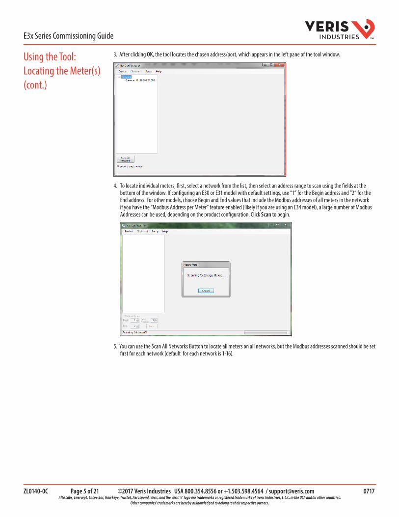
3. After clicking OK, the tool locates the chosen address/port, which appears in the left pane of the tool window.
4. To locate individual meters, first, select a network from the list, then select an address range to scan using the fields at the bottom of the window. If configuring an E30 or E31 model with default settings, use “1” for the Begin address and “2” for the End address. For other models, choose Begin and End values that include the Modbus addresses of all meters in the network if you have the “Modbus Address per Meter” feature enabled (likely if you are using an E34 model), a large number of Modbus Addresses can be used, depending on the product configuration. Click Scan to begin.
5. You can use the Scan All Networks Button to locate all meters on all networks, but the Modbus addresses scanned should be set first for each network (default for each network is 1-16).

ZL0140-0C Page 6 of 21 ©2017 Veris Industries USA 800.354.8556 or +1.503.598.4564 / [email protected] 0717 Alta Labs, Enercept, Enspector, Hawkeye, Trustat, Aerospond, Veris, and the Veris ‘V’ logo are trademarks or registered trademarks of Veris Industries, L.L.C. in the USA and/or other countries.
Other companies’ trademarks are hereby acknowledged to belong to their respective owners.
TME3x Series Commissioning Guide
Using the Tool: Locating the Meter(s) (cont.)
Using the Tool: Accessing the Meter(s)
This tool communicates directly with the meter. When you select a meter under a network, or select a different tab, NetConfig will poll the meter and update the settings and/or readings in that tab.
You can use the Data Poll fields at the bottom of the tool to either initiate a new poll manually (using the Now button) or set an interval for repetitive updates. If the Meter is disconnected or powered down, rescan the meter before polling the data. For the remainder of this document, be aware that some tabs in the tool show options not supported by E3x products and that older versions of the E3x firmware do not include all options supported by the latest firmware. Therefore, some options in the tool may be unavailable (grayed out or not visible). This document assumes the user has the latest firmware, so all options supported by E3x models with the latest firmware are described.
All E3x models have one or two Main/Configuration panels with extensive Modbus point maps. The first panel is located at the base address set by the DIP switches (on E3xA/B/C models) or in the GUI (on E3xE models). If the model has the second panel (models with more than 42 input channels), it is located at a different Modbus physical address (base address + 1). Any set of two or three adjacent channels (or any individual channel) can be assigned to a “Logical Meter” that has a simple point map much like a standalone meter would have. It provides multi-phase total measurements as well as measurements for each phase.
Main/Config Panel 1 (all models)
1
2 3
4 5
6 7
8
14
Main/Config Panel 2
(28 meter models) 15 16
17 18
19 20
21 22
28 Modbus Address
(Base Address) Modbus Address (Base Address +1)
Modbus Addresses: (Base Address +1
+ Meter # + Offset_1)
Logical Meters
Modbus Addresses: (Base Address +2
+ Meter # +Offset_2)
From Panel 1 From Panel 2
All measurement data can be accessed through the two Main/Configuration panels (at base address and base address + 1), however an alternate method of accessing the data can be used to simplify integration, especially in applications that are not monitoring full panelboards. This alternate method, referred to as “Logical Meter by Address” is enabled by default on E34x models and disabled on all others. It can be enabled or disabled on any E3x model (see “1. Overview tab” below).
6. When scanning is complete, the left pane shows the meter(s) found at the address/port. The meter ID information is displayed in the main pane. If the tool does not locate a meter, try increasing the Read Timeout setting under the Setup > Communications menu.
ZL0140-0C Page 7 of 21 ©2017 Veris Industries USA 800.354.8556 or +1.503.598.4564 / [email protected] 0717 Alta Labs, Enercept, Enspector, Hawkeye, Trustat, Aerospond, Veris, and the Veris ‘V’ logo are trademarks or registered trademarks of Veris Industries, L.L.C. in the USA and/or other countries.
Other companies’ trademarks are hereby acknowledged to belong to their respective owners.
TME3x Series Commissioning Guide
Using the Tool: Accessing the Meter(s)(cont.)
Using the Tool: Configuring the Main/ Configuration Panel(s)
If “Logical Meters by Address” is used, every Logical Meter that is configured is assigned its own Modbus physical address and presents its simplified Modbus point map at that address. The Modbus addresses of each meter are assigned sequentially, starting at an address that is offset from the base address. Configuration of Real-Time Clock settings, optional features (like “Logical Meters by Address”), Logical Meter assignments and individual phase assignments are all done through the Main/Configuration panels, but individual meter configuration (CT size, individual Alarms, value resets), and all measurement data is accessed through the simple Logical Meter point map. Some settings for resources shared by all meters (Demand and Alarm settings) can be configured either way.
To view the details of a Main/Configuration panel, click on that panel in the left pane. The Panels will be listed in the tree directly under the “E3x” entry. To view the details of a Logical Meter, click on that meter (they are listed in the tree directly under the “E3x_ckt” entry. A series of tabs appears in the main pane. Each tab allows the viewing/editing of certain settings and measurements. Additionally, when a panel is chosen, the Clipboard option in the main toolbar is available. This feature allows the user to use the clipboard to copy, write, or store settings for the entire product.
The Data Poll section below the main pane allows the user to control the frequency of data polling. The default selection in this field is Manual, meaning the data is only polled when the user clicks the Now button. Using the drop-down list, the user can select a time interval for polling to happen automatically. Readings are updated (a) when a new tab is selected, (b) when the data poll is active, and (c) 2 seconds after a reset action is performed. The Data Poll section is always visible and always editable, regardless of which tab is selected.
The rest of this section discusses the information found in each tab of the tool. For all models, start with the section called “Using the Tool: Configure the Main/Configuration Panel(s)”.
Then if you want to view or configure or view individual Logical Meters you have defined:
• If you’re using an E30x or E31x (and are not using the “Logical Meters by Address” feature) go to the section called “Using the Tool: Configuring Logical Meters within a Pane”
• If you’re using an E34x (or ARE using the “Logical Meters by Address” feature) go to the section called “Using the Tool: Configuring Logical Meters at Separate Modbus Addresses”
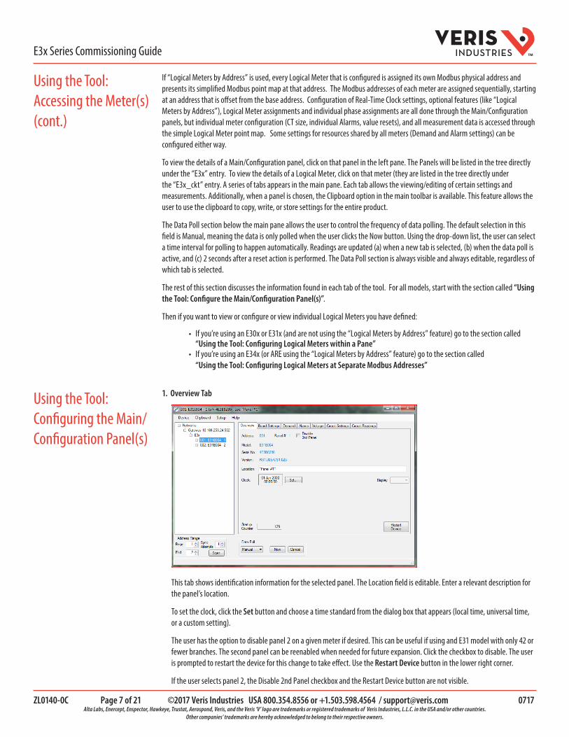
1. Overview Tab
This tab shows identification information for the selected panel. The Location field is editable. Enter a relevant description for the panel’s location.
To set the clock, click the Set button and choose a time standard from the dialog box that appears (local time, universal time, or a custom setting).
The user has the option to disable panel 2 on a given meter if desired. This can be useful if using and E31 model with only 42 or fewer branches. The second panel can be reenabled when needed for future expansion. Click the checkbox to disable. The user is prompted to restart the device for this change to take effect. Use the Restart Device button in the lower right corner.
If the user selects panel 2, the Disable 2nd Panel checkbox and the Restart Device button are not visible.
ZL0140-0C Page 8 of 21 ©2017 Veris Industries USA 800.354.8556 or +1.503.598.4564 / [email protected] 0717 Alta Labs, Enercept, Enspector, Hawkeye, Trustat, Aerospond, Veris, and the Veris ‘V’ logo are trademarks or registered trademarks of Veris Industries, L.L.C. in the USA and/or other countries.
Other companies’ trademarks are hereby acknowledged to belong to their respective owners.
TME3x Series Commissioning Guide
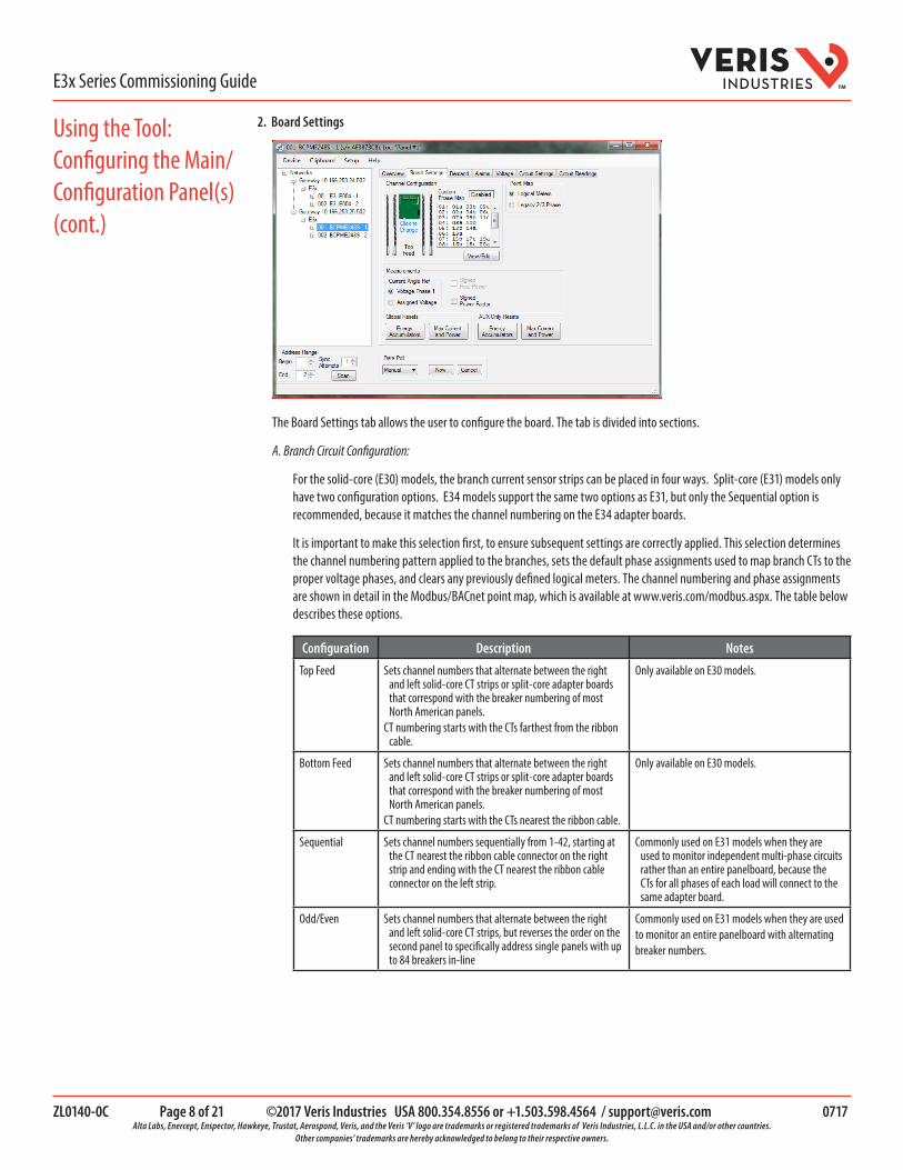
2. Board Settings
The Board Settings tab allows the user to configure the board. The tab is divided into sections.
A. Branch Circuit Configuration:
For the solid-core (E30) models, the branch current sensor strips can be placed in four ways. Split-core (E31) models only have two configuration options. E34 models support the same two options as E31, but only the Sequential option is recommended, because it matches the channel numbering on the E34 adapter boards.
It is important to make this selection first, to ensure subsequent settings are correctly applied. This selection determines the channel numbering pattern applied to the branches, sets the default phase assignments used to map branch CTs to the proper voltage phases, and clears any previously defined logical meters. The channel numbering and phase assignments are shown in detail in the Modbus/BACnet point map, which is available at www.veris.com/modbus.aspx. The table below describes these options.
Configuration Description Notes
Top Feed Sets channel numbers that alternate between the right and left solid-core CT strips or split-core adapter boards that correspond with the breaker numbering of most North American panels.
CT numbering starts with the CTs farthest from the ribbon cable.
Only available on E30 models.
Bottom Feed Sets channel numbers that alternate between the right and left solid-core CT strips or split-core adapter boards that correspond with the breaker numbering of most North American panels.
CT numbering starts with the CTs nearest the ribbon cable.
Only available on E30 models.
Sequential Sets channel numbers sequentially from 1-42, starting at the CT nearest the ribbon cable connector on the right strip and ending with the CT nearest the ribbon cable connector on the left strip.
Commonly used on E31 models when they are used to monitor independent multi-phase circuits rather than an entire panelboard, because the CTs for all phases of each load will connect to the same adapter board.
Odd/Even Sets channel numbers that alternate between the right and left solid-core CT strips, but reverses the order on the second panel to specifically address single panels with up to 84 breakers in-line
Commonly used on E31 models when they are usedto monitor an entire panelboard with alternatingbreaker numbers.
Using the Tool: Configuring the Main/ Configuration Panel(s)(cont.)

ZL0140-0C Page 9 of 21 ©2017 Veris Industries USA 800.354.8556 or +1.503.598.4564 / [email protected] 0717 Alta Labs, Enercept, Enspector, Hawkeye, Trustat, Aerospond, Veris, and the Veris ‘V’ logo are trademarks or registered trademarks of Veris Industries, L.L.C. in the USA and/or other countries.
Other companies’ trademarks are hereby acknowledged to belong to their respective owners.
TME3x Series Commissioning Guide
Click on the configuration image (“Click to Enlarge”). A box opens that illustrates the four options. Click on the desired image to select from the available options. The four options shown here are available for all E30 (solid-core) models.
Below are the two Branch Configuration options available for E31 (split-core) and E34 models.
B. Custom Phase Map
Adjacent to the configuration image is the Custom Phase Map, which allows the user to define logical meters. Click the View/Edit button to see the Circuit Panel form, which shows the default logical circuit configuration and allows changes as needed. The section at the top of this box includes instructions for using this feature.
The E3x can be configured to map any set of 1, 2 or 3 channels that are adjacent in the panel to a logical circuit that provides accurate multi-phase measurement totals. Map these logical meters by writing the desired logical circuit number into a set of registers/data objects provided for each branch and aux channel (per panel). The channels assigned to each logical circuit must be adjacent in the panel (usually used for multi-phase breakers), but there are no limitations on where those adjacent channels are aligned in the panel (any position where a multi-phase breaker can be installed). This functionality is always active, but a user selection affects the how the data can be accessed via Modbus: (a) arranged
Using the Tool: Configuring the Main/ Configuration Panel(s)(cont.)

ZL0140-0C Page 10 of 21 ©2017 Veris Industries USA 800.354.8556 or +1.503.598.4564 / [email protected] 0717 Alta Labs, Enercept, Enspector, Hawkeye, Trustat, Aerospond, Veris, and the Veris ‘V’ logo are trademarks or registered trademarks of Veris Industries, L.L.C. in the USA and/or other countries.
Other companies’ trademarks are hereby acknowledged to belong to their respective owners.
TME3x Series Commissioning Guide
either by logical circuit number (looks more like a collection of individual meters) or (b) by measurement type (arranged similarly to the single-phase data section of the point map).
The Custom Phase Map selections at the left allow you to override the default settings of the product and preload the channels to match common 2-phase (AB) or three-phase (ABC) panel configurations. You can also set any channel to any specific phase. Click the Enable button to all changes and then either use one of the Phase preloads buttons to preload all phases or select an individual channel and right-click to open a dialog of the three phase assignment selections.
The selections at the bottom of the page allow you Clear all Logical Meters, Delete individual ones or Fill (preload) all channels with 1-phase, 2-phase or 3-phase meters.
To set Logical meters individually, Clear the list (recommended), then select 1, 2 or 3 adjacent channels and then select an unused [non-gray] Logical Meter number from the list on the right.
Click OK to save changes and return to the Board Settings tab.
C. Point Map
The E3x can now be configured to select a preferred version of the Modbus registers in the address range 4000 to 9999. If enabled (default), the logical meters by measurement type is active. Otherwise, the legacy point maps for 2-phase and 3-phase breakers used in older E3x models is active. The logical meters’ functionality can also be accessed via the “Logical Map by Circuit” section of the point map (address range 10000 to 55000), regardless of the state of this selection.
D. Measurements
The features in this section of the pane are defined as follows:
Phase angle reference The E3x measures the phase angle of every current and voltage input. The user can select whether the phase angles are stated relative to an absolute reference (the phase angle of voltage input V1) or relative to the voltage phase assigned to that specific current input channel.
Signed power (E31A/B/E models only)
Users can configure the meter to report power as a signed value indicating whether the power is currently being delivered (imported from the grid) or received (exported to the grid) for channels with generation sources or bi-directional (regenerative) loads. When signed power is disabled, the energy accumulators include all energy measured, regardless of direction. When signed power is enabled, the energy accumulators only include all energy delivered (imported from the grid).
Signed power factor By default the E3x reports power factor as an unsigned value. The user can set it to report as a signed value, where the sign indicates whether the current phase angle leads or lags the corresponding voltage phase.
E. Global Resets and AUX Only Resets
These buttons clear data from the associated registers.
Using the Tool: Configuring the Main/ Configuration Panel(s)(cont.)

ZL0140-0C Page 11 of 21 ©2017 Veris Industries USA 800.354.8556 or +1.503.598.4564 / [email protected] 0717 Alta Labs, Enercept, Enspector, Hawkeye, Trustat, Aerospond, Veris, and the Veris ‘V’ logo are trademarks or registered trademarks of Veris Industries, L.L.C. in the USA and/or other countries.
Other companies’ trademarks are hereby acknowledged to belong to their respective owners.
TME3x Series Commissioning Guide
3. Demand Tab
Use this tab to set up the demand sub-internal duration and the sub-interval counter. This tab also allows the user to reset these values using the Reset button. The Present Demand and Max Demand values can be reset using the buttons at the right.
The E3xE offers two mechanisms for driving the demand and snapshot time interval, an interval timer and an RTC (real-time clock). The legacy mode (default) uses an interval timer that does not need to be set to an absolute time. When using the interval timer the demand/snapshot interval can be set from 10 to 32767 seconds (over 9 hours). The RTC is enabled by selecting Sync to Clock, and then setting a specific date and time to synchronize the results with a larger system. The RTC must first be set in order to run and capture demand values and energy snapshots. When power is interrupted, the RTC resets to a default date and time and must be set again in order to run. When using the RTC, the demand/snapshot interval can be set from 10 to 3,600 seconds (1 hour).
4. Alarms Tab
This tab is used to configure the alarm thresholds. This tab is also divided into sections.
A. Current
There are two types of alarms, Latching and Non-Latching.
Non-Latching Alarm Settings Defined
The instantaneous current alarm setup parameters define the maximum (high alarm) and minimum (low alarm) limits for all branch and main circuits monitored by the E3x. Instantaneous current alarms are ON only if the alarm conditions are met. These alarms are reset automatically (alarm is turned OFF or cleared when circuit current is within the normal range).
Using the Tool: Configuring the Main/ Configuration Panel(s)(cont.)

ZL0140-0C Page 12 of 21 ©2017 Veris Industries USA 800.354.8556 or +1.503.598.4564 / [email protected] 0717 Alta Labs, Enercept, Enspector, Hawkeye, Trustat, Aerospond, Veris, and the Veris ‘V’ logo are trademarks or registered trademarks of Veris Industries, L.L.C. in the USA and/or other countries.
Other companies’ trademarks are hereby acknowledged to belong to their respective owners.
TME3x Series Commissioning Guide
High Alarm Thresholds: Type the instantaneous current value, expressed as a percentage of the breaker size (default = 60%). When the circuit current exceeds that value, the high current alarm is activated. To disable any alarms, set the specific high alarm threshold to zero. Example: If the threshold is set to 60%, the high alarm is activated when instantaneous current for a 20 A breaker exceeds 12 A (i.e. 20 A x 0.60).
Low Alarm Thresholds: Type the instantaneous current value, expressed as a percentage of the breaker size (default = 7.5%). When the circuit current falls below that value, the low current alarm is activated. To disable any alarms, set the specific low alarm threshold to zero. Example: If the threshold is set to 5%, the low alarm is activated when instantaneous current for a 20 A breaker drops below 1 A (i.e. 20 A x 0.05).
Hysteresis: Type the value, expressed as a percentage of the alarm threshold, that defines how much the circuit current must fall below the High alarm threshold or rise above the Low alarm threshold, to determine the alarm’s “OFF” state (default = 5%). Example: If hysteresis is set to 5%, the “OFF” state for a high alarm threshold of 12 A is 11.4 A and below (i.e. 12 A minus (12 A x 0.05)), while the “OFF” state for a low alarm threshold of 1 A is 1.05 A and above (i.e. 1 A plus (1 A x 0.05)).
Time
Amps
1
2
34
High
High - hysteresis
Low + hysteresisLow
1 High Alarm Set On2 High Alarm Set O�3 Low Alarm Set On4 Low Alarm Set O�
Latching Alarm Settings Defined
High-High Alarm Delay (s): Number of seconds the current in a circuit needs to be continuously above the High-High Alarm Threshold before the High-High alarm is activated (default = 10 sec).
High Alarm Delay (s): Number of seconds the current in a circuit needs to be continuously above the High Alarm Threshold before the High alarm is activated (default = 10 sec).
Low Alarm Delay (s): Number of seconds the current in a circuit needs to be continuously below the Low Alarm Threshold before the Low alarm is activated (default = 10 sec).
Low-Low Alarm Delay (s): Number of seconds the current in a circuit needs to be continuously below the Low-Low Alarm Threshold before the Low-Low alarm is activated (default = 10 sec).
Latching Alarm On Time (s): Number of seconds the current in a circuit needs to stay above the low-low alarm threshold level before the latching alarms are armed/enabled for that channel (default = 10 sec).
Latching Alarm Off Time (s): Number of seconds the current in a circuit needs to be below the Low-Low Alarm Threshold level before the latching alarm is de-activated (default = 30 s). After this point, on this channel, all latching alarms are disabled.
High-High Alarm Threshold (%): Limit for the High-High current alarm state, expressed as a percentage of the breaker size (default = 70%). For example, the High-High alarm threshold for a 20 A breaker is 14 A (i.e., 20 x 0.70). To disable this alarm (for all channels) set its threshold value to 0%.
High Alarm Threshold (%): Limit for the High current alarm state, expressed as a percentage of the breaker size (default = 60%). For example, the High alarm threshold for a 20 A breaker is 12 A (i.e., 20 x 0.60). To disable this alarm (for all channels) set its threshold value to 0%.
Low Alarm Threshold (%): Limit for the Low current alarm state, expressed as a percentage of the breaker size (default = 7.5%). For example, the Low alarm threshold for a 20 A breaker is 1.5 A (i.e., 20 x 0.075). To disable this alarm (for all channels) set its threshold value to 0%.
Using the Tool: Configuring the Main/ Configuration Panel(s)(cont.)

ZL0140-0C Page 13 of 21 ©2017 Veris Industries USA 800.354.8556 or +1.503.598.4564 / [email protected] 0717 Alta Labs, Enercept, Enspector, Hawkeye, Trustat, Aerospond, Veris, and the Veris ‘V’ logo are trademarks or registered trademarks of Veris Industries, L.L.C. in the USA and/or other countries.
Other companies’ trademarks are hereby acknowledged to belong to their respective owners.
TME3x Series Commissioning Guide
Low-Low Alarm Threshold (%): Limit for the Low-Low current alarm state, expressed as a percentage of the breaker size (default = 2.5%). For example, the Low-Low alarm threshold for a 20 A breaker is 0.5 A (i.e., 20 x 0.025). To disable this alarm (for all channels) set its threshold value to 0%.
B. Voltage
Set the Over and Under threshold voltages and the preferred delay time. Also set the hysteresis value.
C. Alarm grid
This section shows the present global alarm states for each phase. A number in a cell indicates the number of times a particular alarm has been set. The Reset button below allows the user to reset these counters to zero.
5. Voltage Tab
This tab allows the user to view the frequency, line-line and line-neutral voltages, and the phase angles in real time. This tab is display-only, with no editable fields.
6. Circuit Settings
This tab allows the user to input the CT and breaker sizes for the circuits as they were defined in the Board Settings tab. Use the Parameters drop-down list at the top to select.
A. CT Size
The table that appears below the Parameters field shows all circuits. For solid-core (E30) models, the CT sizes are fixed at 100 A. For split-core (E31) models, the fields in the Combined and CT Size columns are editable and can be set to 50 A, 100 A or 200
Using the Tool: Configure the Main/Configuration Panel(s)(cont.)
ZL0140-0C Page 14 of 21 ©2017 Veris Industries USA 800.354.8556 or +1.503.598.4564 / [email protected] 0717 Alta Labs, Enercept, Enspector, Hawkeye, Trustat, Aerospond, Veris, and the Veris ‘V’ logo are trademarks or registered trademarks of Veris Industries, L.L.C. in the USA and/or other countries.
Other companies’ trademarks are hereby acknowledged to belong to their respective owners.
TME3x Series Commissioning Guide
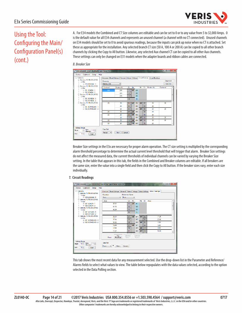
A. For E34 models the Combined and CT Size columns are editable and can be set to 0 or to any value from 5 to 32,000 Amps. 0 is the default value for all E34 channels and represents an unused channel (a channel with no CT connected). Unused channels on E34 models should be set to 0 to avoid spurious readings, because the inputs can pick up noise when no CT is attached. Set these as appropriate for the installation. Any selected branch CT size (50 A, 100 A or 200 A) can be copied to all other branch channels by clicking the Copy to All button. Likewise, any selected Aux channel CT can be copied to all other Aux channels. These settings can only be changed on E31 models when the adapter boards and ribbon cables are connected.
B. Breaker Size
Breaker Size settings in the E3x are necessary for proper alarm operation. The CT size setting is multiplied by the corresponding alarm threshold percentage to determine the actual current level threshold that will trigger that alarm. Breaker Size settings do not affect the measured data, the current thresholds of individual channels can be varied by varying the Breaker Size setting. In the table that appears in this tab, the fields in the Combined and Breaker columns are editable. If all breakers are the same size, enter the value into a single field and then click the Copy to All button. If the breaker sizes vary, enter each size individually.
7. Circuit Readings
This tab shows the most recent data for any measurement selected. Use the drop-down list in the Parameter and Reference/Alarms fields to select what values to view. The table below repopulates with the data values selected, according to the option selected in the Data Polling section.
Using the Tool: Configuring the Main/Configuration Panel(s)(cont.)

ZL0140-0C Page 15 of 21 ©2017 Veris Industries USA 800.354.8556 or +1.503.598.4564 / [email protected] 0717 Alta Labs, Enercept, Enspector, Hawkeye, Trustat, Aerospond, Veris, and the Veris ‘V’ logo are trademarks or registered trademarks of Veris Industries, L.L.C. in the USA and/or other countries.
Other companies’ trademarks are hereby acknowledged to belong to their respective owners.
TME3x Series Commissioning Guide
In this tab, certain parameter selections (such as Max_Current) bring up a series of reset buttons below the table that allow the user to reset that parameter on the board, Logical Meter, or branch level. The buttons are enabled/disabled based on what cell is selected in the table. For all parameters and alarms selected, the information in the table is display-only, with no editable fields.
To configure individual Logical Meters within a panel, return to the left pane and click the + sign next to the panel to display the available circuit(s), or double-click a meter or branch number from the Circuit Settings/Readings table. A new series of tabs appears in the main pane. This section discusses the information found in each tab.
1. Demand Tab
Use this tab to set up the demand sub-internal duration and the sub-interval counter for the selected Logical Meter. This tab also allows the user to reset these values using the Reset button. The Present Demand and Max Demand values can be reset using the buttons at the bottom of the pane. These are the same settings as described in the previous section. Changes to the Demand settings in any tab will affect all logical meters the same physical product (and the corresponding Main/Configuration panels.
Using the Tool: Configuring the Main/Configuration Panel(s)(cont.)
Using the Tool: Configuring the Logical Meters within a Panel

ZL0140-0C Page 16 of 21 ©2017 Veris Industries USA 800.354.8556 or +1.503.598.4564 / [email protected] 0717 Alta Labs, Enercept, Enspector, Hawkeye, Trustat, Aerospond, Veris, and the Veris ‘V’ logo are trademarks or registered trademarks of Veris Industries, L.L.C. in the USA and/or other countries.
Other companies’ trademarks are hereby acknowledged to belong to their respective owners.
TME3x Series Commissioning Guide
2. Alarms Tab
Alarms are defined previously in this document, in the Configure the Meter section. Use this tab to view alarm states and reset latching alarms for the selected Logical Meter. Note that there are separate sub-tabs along the left edge of the pane for latching and non-latching alarms.
3. Voltage Tab
This tab allows the user to view the line-line and line neutral voltages and the phase angles for each Logical Meter in real time. This tab is display-only, with no editable fields. Since all Logical Meters share the same voltage connection, all of them will read the same Voltage values.
Using the Tool: Configuring the Logical Meters within a Panel (cont.)
ZL0140-0C Page 17 of 21 ©2017 Veris Industries USA 800.354.8556 or +1.503.598.4564 / [email protected] 0717 Alta Labs, Enercept, Enspector, Hawkeye, Trustat, Aerospond, Veris, and the Veris ‘V’ logo are trademarks or registered trademarks of Veris Industries, L.L.C. in the USA and/or other countries.
Other companies’ trademarks are hereby acknowledged to belong to their respective owners.
TME3x Series Commissioning Guide
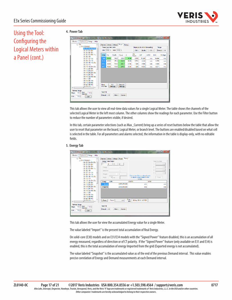
4. Power Tab
This tab allows the user to view all real-time data values for a single Logical Meter. The table shows the channels of the selected Logical Meter in the left most column. The other columns show the readings for each parameter. Use the Filter button to reduce the number of parameters visible, if desired.
In this tab, certain parameter selections (such as Max_Current) bring up a series of reset buttons below the table that allow the user to reset that parameter on the board, Logical Meter, or branch level. The buttons are enabled/disabled based on what cell is selected in the table. For all parameters and alarms selected, the information in the table is display-only, with no editable fields.
5. Energy Tab
This tab allows the user for view the accumulated Energy value for a single Meter.
The value labeled “Import” is the present total accumulation of Real Energy.
On solid-core (E30) models and on E31/E34 models with the “Signed Power” feature disabled, this is an accumulation of all energy measured, regardless of direction or of CT polarity. If the “Signed Power” feature (only available on E31 and E34) is enabled, this is the total accumulation of energy Imported from the grid (Exported energy is not accumulated).
The value labeled “Snapshot” is the accumulated value as of the end of the previous Demand interval. This value enables precise correlation of Energy and Demand measurements at each Demand interval.
Using the Tool: Configuring the Logical Meters within a Panel (cont.)

ZL0140-0C Page 18 of 21 ©2017 Veris Industries USA 800.354.8556 or +1.503.598.4564 / [email protected] 0717 Alta Labs, Enercept, Enspector, Hawkeye, Trustat, Aerospond, Veris, and the Veris ‘V’ logo are trademarks or registered trademarks of Veris Industries, L.L.C. in the USA and/or other countries.
Other companies’ trademarks are hereby acknowledged to belong to their respective owners.
TME3x Series Commissioning Guide
To configure individual Logical Meters by Modbus Address, return to the left pane and select a Logical Meter from the list shown below the “E3x_ckt” entry. A new series of tabs appears in the main pane. This section discusses the information found in each tab.
1. Overview Tab
This tab shows identification information for the selected Logical Meter. The fields on this tab are not editable – to set the clock, use the overview tab for the Main/Configuration panel.
2. Meter Settings Tab
Using the Tool: Configuring Logical Meters at Separate Modbus Addresses
ZL0140-0C Page 19 of 21 ©2017 Veris Industries USA 800.354.8556 or +1.503.598.4564 / [email protected] 0717 Alta Labs, Enercept, Enspector, Hawkeye, Trustat, Aerospond, Veris, and the Veris ‘V’ logo are trademarks or registered trademarks of Veris Industries, L.L.C. in the USA and/or other countries.
Other companies’ trademarks are hereby acknowledged to belong to their respective owners.
TME3x Series Commissioning Guide
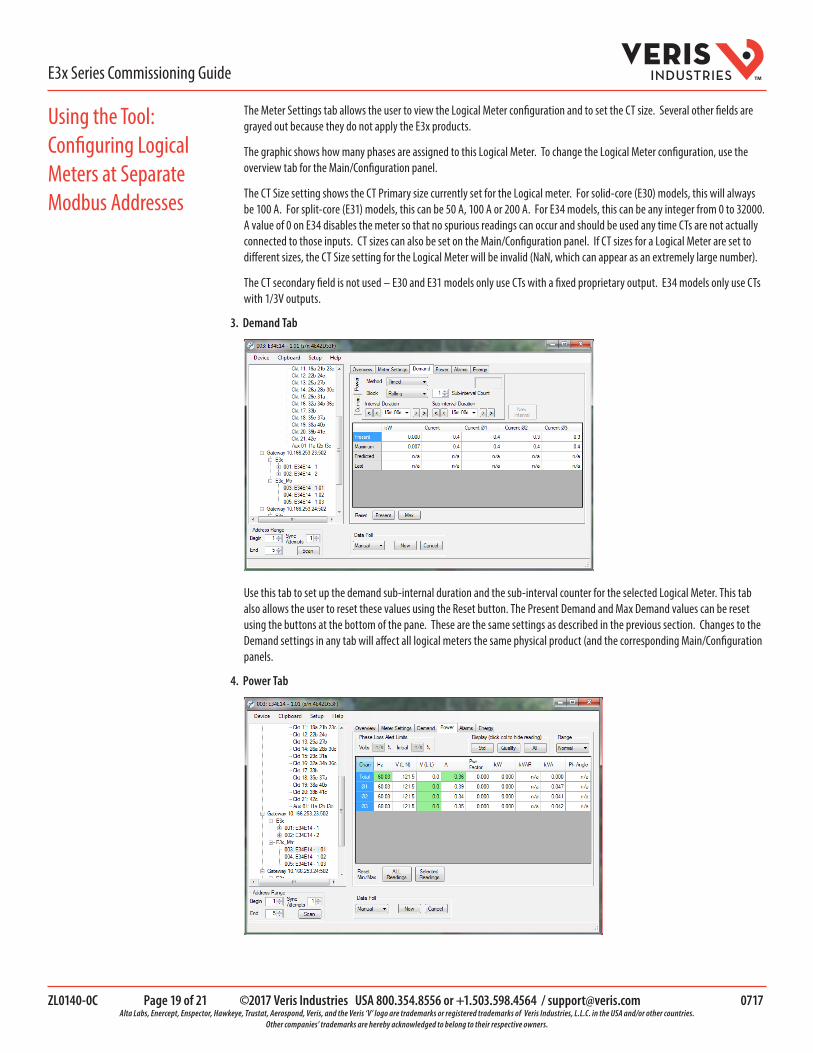
The Meter Settings tab allows the user to view the Logical Meter configuration and to set the CT size. Several other fields are grayed out because they do not apply the E3x products.
The graphic shows how many phases are assigned to this Logical Meter. To change the Logical Meter configuration, use the overview tab for the Main/Configuration panel.
The CT Size setting shows the CT Primary size currently set for the Logical meter. For solid-core (E30) models, this will always be 100 A. For split-core (E31) models, this can be 50 A, 100 A or 200 A. For E34 models, this can be any integer from 0 to 32000. A value of 0 on E34 disables the meter so that no spurious readings can occur and should be used any time CTs are not actually connected to those inputs. CT sizes can also be set on the Main/Configuration panel. If CT sizes for a Logical Meter are set to different sizes, the CT Size setting for the Logical Meter will be invalid (NaN, which can appear as an extremely large number).
The CT secondary field is not used – E30 and E31 models only use CTs with a fixed proprietary output. E34 models only use CTs with 1/3V outputs.
3. Demand Tab
Use this tab to set up the demand sub-internal duration and the sub-interval counter for the selected Logical Meter. This tab also allows the user to reset these values using the Reset button. The Present Demand and Max Demand values can be reset using the buttons at the bottom of the pane. These are the same settings as described in the previous section. Changes to the Demand settings in any tab will affect all logical meters the same physical product (and the corresponding Main/Configuration panels.
4. Power Tab
Using the Tool: Configuring Logical Meters at Separate Modbus Addresses
ZL0140-0C Page 20 of 21 ©2017 Veris Industries USA 800.354.8556 or +1.503.598.4564 / [email protected] 0717 Alta Labs, Enercept, Enspector, Hawkeye, Trustat, Aerospond, Veris, and the Veris ‘V’ logo are trademarks or registered trademarks of Veris Industries, L.L.C. in the USA and/or other countries.
Other companies’ trademarks are hereby acknowledged to belong to their respective owners.
TME3x Series Commissioning Guide
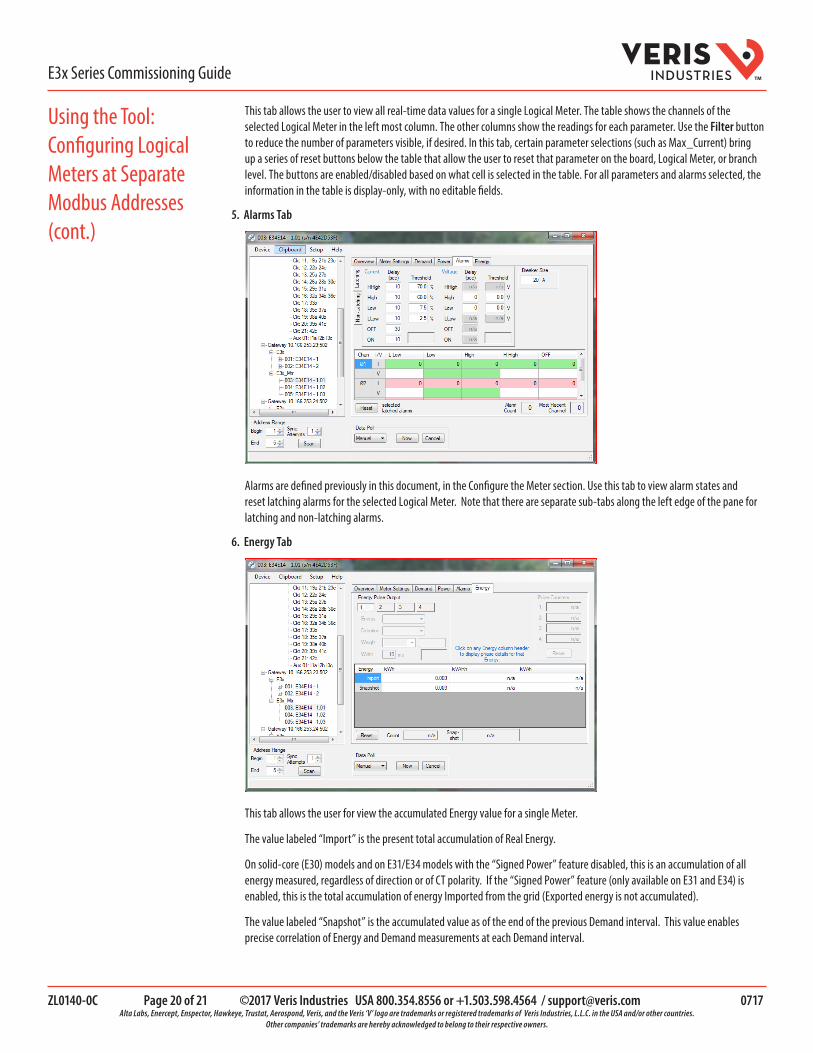
This tab allows the user to view all real-time data values for a single Logical Meter. The table shows the channels of the selected Logical Meter in the left most column. The other columns show the readings for each parameter. Use the Filter button to reduce the number of parameters visible, if desired. In this tab, certain parameter selections (such as Max_Current) bring up a series of reset buttons below the table that allow the user to reset that parameter on the board, Logical Meter, or branch level. The buttons are enabled/disabled based on what cell is selected in the table. For all parameters and alarms selected, the information in the table is display-only, with no editable fields.
5. Alarms Tab
Alarms are defined previously in this document, in the Configure the Meter section. Use this tab to view alarm states and reset latching alarms for the selected Logical Meter. Note that there are separate sub-tabs along the left edge of the pane for latching and non-latching alarms.
6. Energy Tab
This tab allows the user for view the accumulated Energy value for a single Meter.
The value labeled “Import” is the present total accumulation of Real Energy.
On solid-core (E30) models and on E31/E34 models with the “Signed Power” feature disabled, this is an accumulation of all energy measured, regardless of direction or of CT polarity. If the “Signed Power” feature (only available on E31 and E34) is enabled, this is the total accumulation of energy Imported from the grid (Exported energy is not accumulated).
The value labeled “Snapshot” is the accumulated value as of the end of the previous Demand interval. This value enables precise correlation of Energy and Demand measurements at each Demand interval.
Using the Tool: Configuring Logical Meters at Separate Modbus Addresses (cont.)

ZL0140-0C Page 21 of 21 ©2017 Veris Industries USA 800.354.8556 or +1.503.598.4564 / [email protected] 0717 Alta Labs, Enercept, Enspector, Hawkeye, Trustat, Aerospond, Veris, and the Veris ‘V’ logo are trademarks or registered trademarks of Veris Industries, L.L.C. in the USA and/or other countries.
Other companies’ trademarks are hereby acknowledged to belong to their respective owners.
TME3x Series Commissioning Guide
The Commands under the “Clipboard” menu list allow you to copy all product settings to a clipboard and paste them to a different unit of the identical model type. If you have added several identical products in the Network tree on the left, you can simply select one product, select Copy Selections to Clipboard, then select another product, select Paste Selections from Clipboard to duplicate the configuration exactly. You can also use Save Clipboard to File and Load Clipboard from File to save the settings and restore them later to use on other units. You can select Show Clipboard at any time to review your settings. The Clipboard is internal to NetConfig is not connected to the Windows clipboard.
Copying Settings from One Unit to Another


