› - › media › Files › SLI › SLI... · Created Date: 6/26/2017 4:33:12 PM
Upload
eric-santucciCategory
view
213download
0
7/27/2019 (E3241)_M2N4-SLI
http://slidepdf.com/reader/full/e3241m2n4-sli 1/138
M o
t h
e r b o a r d
M2N4-SLI

7/27/2019 (E3241)_M2N4-SLI
http://slidepdf.com/reader/full/e3241m2n4-sli 2/138
ii
Copyright © 2006 ASUSTeK COMPUTER INC. All Rights Reserved.
No part of this manual, including the products and software described in it, may be reproduced,transmitted, transcribed, stored in a retrieval system, or translated into any language in any form or by anymeans, except documentation kept by the purchaser for backup purposes, without the express writtenpermission of ASUSTeK COMPUTER INC. (“ASUS”).
Product warranty or service will not be extended if: (1) the product is repaired, modied oraltered, unless such repair, modication of alteration is authorized in writing by ASUS; or (2)the serial number of the product is defaced or missing.
ASUS PROVIDES THIS MANUAL “AS IS” WITHOUT WARRANTY OF ANY KIND, EITHEREXPRESS OR IMPLIED, INCLUDING BUT NOT LIMITED TO THE IMPLIED WARRANTIES
OR CONDITIONS OF MERCHANTABILITY OR FITNESS FOR A PARTICULAR PURPOSE.IN NO EVENT SHALL ASUS, ITS DIRECTORS, OFFICERS, EMPLOYEES OR AGENTS BELIABLE FOR ANY INDIRECT, SPECIAL, INCIDENTAL, OR CONSEQUENTIAL DAMAGES(INCLUDING DAMAGES FOR LOSS OF PROFITS, LOSS OF BUSINESS, LOSS OF USEOR DATA, INTERRUPTION OF BUSINESS AND THE LIKE), EVEN IF ASUS HAS BEENADVISED OF THE POSSIBILITY OF SUCH DAMAGES ARISING FROM ANY DEFECT ORERROR IN THIS MANUAL OR PRODUCT.
SPECIFICATIONS AND INFORMATION CONTAINED IN THIS MANUAL ARE FURNISHEDFOR INFORMATIONAL USE ONLY, AND ARE SUBJECT TO CHANGE AT ANY TIMEWITHOUT NOTICE, AND SHOULD NOT BE CONSTRUED AS A COMMITMENT BYASUS. ASUS ASSUMES NO RESPONSIBILITY OR LIABILITY FOR ANY ERRORS ORINACCURACIES THAT MAY APPEAR IN THIS MANUAL, INCLUDING THE PRODUCTSAND SOFTWARE DESCRIBED IN IT.
Products and corporate names appearing in this manual may or may not be registeredtrademarks or copyrights of their respective companies, and are used only for identication orexplanation and to the owners’ benet, without intent to infringe.
E3241
Second Edition
May 2007

7/27/2019 (E3241)_M2N4-SLI
http://slidepdf.com/reader/full/e3241m2n4-sli 3/138
iii
Contents
Notices ........................................................................................................ vii
Safety information .................................................................................... viii
About this guide ......................................................................................... ix
Typography .................................................................................................. x
M2N4-SLI specications summary ........................................................... xi
Chapter 1: Product introduction
1.1 Welcome! ...................................................................................... 1-1
1.2 Package contents......................................................................... 1-1
1.3 Special features............................................................................ 1-21.3.1 Product highlights ........................................................... 1-2
1.3.2 ASUS Special features ................................................... 1-4
Chapter 2: Hardware information
2.1 Before you proceed ..................................................................... 2-1
2.2 Motherboard overview ................................................................. 2-2
2.2.1 Placement direction ........................................................ 2-2
2.2.2 Screw holes ....................................................................2-22.2.3 Motherboard layout .........................................................2-3
2.2.4 Layout Contents ..............................................................2-4
2.3 Central Processing Unit (CPU) ................................................... 2-5
2.3.1 Installing the CPU ...........................................................2-5
2.3.2 Installing the heatsink and fan ........................................ 2-7
2.4 System memory ......................................................................... 2-10
2.4.1 Overview .......................................................................2-102.4.2 Memory congurations ..................................................2-10
2.4.3 Installing a DIMM .......................................................... 2-15
2.4.4 Removing a DIMM ........................................................2-15
2.5 Expansion slots.......................................................................... 2-16
2.5.1 Installing an expansion card ......................................... 2-16
2.5.2 Conguring an expansion card ..................................... 2-16
2.5.3 Interrupt assignments ................................................... 2-17
2.5.4 PCI slots ........................................................................2-17
2.5.5 PCI Express x1 slot .......................................................2-18
2.5.6 PCI Express x16 slots ...................................................2-18

7/27/2019 (E3241)_M2N4-SLI
http://slidepdf.com/reader/full/e3241m2n4-sli 4/138
iv
Contents
2.6 Jumpers ...................................................................................... 2-19
2.7 Connectors ................................................................................. 2-21
2.7.1 Rear panel connectors ..................................................2-21
2.7.2 Internal connectors ....................................................... 2-22
Chapter 3: Powering up
3.1 Starting up for the rst time........................................................ 3-1
3.2 Powering off the computer .......................................................... 3-2
3.2.1 Using the OS shut down function .................................... 3-2
3.2.2 Using the dual function power switch .............................. 3-2
Chapter 4: BIOS setup
4.1 Managing and updating your BIOS ............................................ 4-1
4.1.1 Creating a bootable oppy disk .......................................4-1
4.1.2 Updating the BIOS ..........................................................4-2
4.1.3 Saving the current BIOS le ............................................4-4
4.1.4 ASUS CrashFree BIOS 3 utility ...................................... 4-5
4.1.5 ASUS EZ Flash 2 utility ...................................................4-74.1.6 ASUS Update utility ........................................................ 4-8
4.2 BIOS setup program .................................................................. 4-11
4.2.1 BIOS menu screen ........................................................4-12
4.2.2 Menu bar .......................................................................4-12
4.2.3 Legend bar ....................................................................4-13
4.2.4 Menu items ...................................................................4-13
4.2.5 Sub-menu items ............................................................4-134.2.6 Conguration elds .......................................................4-13
4.2.7 Pop-up window ............................................................. 4-14
4.2.8 General help .................................................................4-14
4.3 Main menu .................................................................................. 4-15
4.3.1 System Time ................................................................ 4-15
4.3.2 System Date ................................................................ 4-15
4.3.3 Legacy Diskette A ........................................................ 4-15
4.3.5 Primary and Secondary IDE Master/Slave ................... 4-16
4.3.6 SATA 1, 2, 3, 4 .............................................................. 4-18
4.3.7 HDD SMART Monitoring ...............................................4-19

7/27/2019 (E3241)_M2N4-SLI
http://slidepdf.com/reader/full/e3241m2n4-sli 5/138
v
Contents
4.3.8 Installed Memory ...........................................................4-19
4.4 Advanced menu ......................................................................... 4-20
4.4.1 JumperFree Conguration ............................................ 4-20
4.4.3 CPU Conguration ........................................................4-23
4.4.4 PCIPnP .........................................................................4-25
4.4.5 Onboard Device Conguration ......................................4-26
4.4.6 SLI Conguration ..........................................................4-31
4.5 Power menu ................................................................................ 4-32
4.5.1 ACPI Suspend Type ..................................................... 4-32
4.5.2 ACPI APIC Support ...................................................... 4-32
4.5.3 APM Conguration ........................................................4-33
4.5.4 Hardware Monitor ......................................................... 4-35
4.6 Boot menu .................................................................................. 4-37
4.6.1 Boot Device Priority ...................................................... 4-37
4.6.2 Removable Drives .........................................................4-38
4.6.3 Hard Disk Drives ...........................................................4-38
4.6.4 Boot Settings Conguration ......................................... 4-394.6.5 Security .........................................................................4-41
4.7 Tools menu ................................................................................. 4-43
ASUS EZ Flash 2 .........................................................................4-43
4.8 Exit menu .................................................................................... 4-44
Chapter 5: Software support
5.1 Installing an operating system ................................................... 5-1
5.2 Support CD information .............................................................. 5-1
5.2.1 Running the support CD ................................................. 5-1
5.2.2 Drivers menu ................................................................... 5-2
5.2.3 Utilities menu .................................................................. 5-3
5.2.4 Manuals menu ................................................................ 5-4
5.2.5 ASUS Contact information .............................................. 5-5
5.2.6 Other information ............................................................ 5-5
5.3 Software information ................................................................... 5-85.3.1 Cool ‘n’ Quiet!™ Technology ........................................... 5-8
5.3.2 ASUS PC Probe II ......................................................... 5-10
5.4 RAID congurations .................................................................. 5-16

7/27/2019 (E3241)_M2N4-SLI
http://slidepdf.com/reader/full/e3241m2n4-sli 6/138
vi
Contents
5.4.1 Installing hard disks ...................................................... 5-17
5.4.2 NVIDIA® RAID congurations........................................ 5-18
5.5 Creating a RAID driver disk ....................................................... 5-25
Chapter 6: NVIDIA® SLI™ technology support
6.1 Overview ....................................................................................... 6-1
Requirements ................................................................................. 6-1
6.2 Dual graphics card setup ............................................................ 6-2
6.2.1 Installing SLI-ready graphics cards ................................. 6-2
6.2.2 Installing the device drivers ............................................. 6-56.2.3 Enabling the multi-GPU feature in Windows ................... 6-5

7/27/2019 (E3241)_M2N4-SLI
http://slidepdf.com/reader/full/e3241m2n4-sli 7/138
vii
Notices
Federal Communications Commission Statement
This device complies with Part 15 of the FCC Rules. Operation is subject to thefollowing two conditions:
• This device may not cause harmful interference, and
• This device must accept any interference received including interference that
may cause undesired operation.
This equipment has been tested and found to comply with the limits for aClass B digital device, pursuant to Part 15 of the FCC Rules. These limits are
designed to provide reasonable protection against harmful interference in a
residential installation. This equipment generates, uses and can radiate radiofrequency energy and, if not installed and used in accordance with manufacturer’s
instructions, may cause harmful interference to radio communications. However,
there is no guarantee that interference will not occur in a particular installation. If
this equipment does cause harmful interference to radio or television reception,which can be determined by turning the equipment off and on, the user is
encouraged to try to correct the interference by one or more of the following
measures:
• Reorient or relocate the receiving antenna.
• Increase the separation between the equipment and receiver.
• Connect the equipment to an outlet on a circuit different from that to which the
receiver is connected.
• Consult the dealer or an experienced radio/TV technician for help.
Canadian Department of Communications Statement
This digital apparatus does not exceed the Class B limits for radio noise emissions
from digital apparatus set out in the Radio Interference Regulations of the
Canadian Department of Communications.
This class B digital apparatus complies with CanadianICES-003.
The use of shielded cables for connection of the monitor to the graphics card isrequired to assure compliance with FCC regulations. Changes or modicationsto this unit not expressly approved by the party responsible for compliancecould void the user’s authority to operate this equipment.

7/27/2019 (E3241)_M2N4-SLI
http://slidepdf.com/reader/full/e3241m2n4-sli 8/138
viii
The symbol of the crossed out wheeled bin indicates that the product (electricaland electronic equipment) should not be placed in municipal waste. Check local
regulations for disposal of electronic products.
Safety information
Electrical safety
• To prevent electrical shock hazard, disconnect the power cable from theelectrical outlet before relocating the system.
• When adding or removing devices to or from the system, ensure that the powercables for the devices are unplugged before the signal cables are connected. If
possible, disconnect all power cables from the existing system before you add
a device.
• Before connecting or removing signal cables from the motherboard, ensure
that all power cables are unplugged.
• Seek professional assistance before using an adapter or extension cord.These devices could interrupt the grounding circuit.
• Make sure that your power supply is set to the correct voltage in your area. If
you are not sure about the voltage of the electrical outlet you are using, contactyour local power company.
• If the power supply is broken, do not try to x it by yourself. Contact a qualied
service technician or your retailer.
Operation safety• Before installing the motherboard and adding devices on it, carefully read all
the manuals that came with the package.
• Before using the product, make sure all cables are correctly connected and the
power cables are not damaged. If you detect any damage, contact your dealer
immediately.
• To avoid short circuits, keep paper clips, screws, and staples away from
connectors, slots, sockets and circuitry.
• Avoid dust, humidity, and temperature extremes. Do not place the product inany area where it may become wet.
• Place the product on a stable surface.
• If you encounter technical problems with the product, contact a qualied
service technician or your retailer.

7/27/2019 (E3241)_M2N4-SLI
http://slidepdf.com/reader/full/e3241m2n4-sli 9/138
ix
About this guide
This user guide contains the information you need when installing and conguring
the motherboard.
How this guide is organized
This manual contains the following parts:
• Chapter 1: Product introduction
This chapter describes the features of the motherboard and the new
technology it supports.
• Chapter 2: Hardware information
This chapter lists the hardware setup procedures that you have to performwhen installing system components. It includes description of the switches,
jumpers, and connectors on the motherboard.
• Chapter 3: Powering up
This chapter describes the power up sequence, the vocal POST messages,
and ways of shutting down the system.
• Chapter 4: BIOS setup
This chapter tells how to change system settings through the BIOS Setupmenus. Detailed descriptions of the BIOS parameters are also provided.
• Chapter 5: Software support
This chapter describes the contents of the support CD that comes with the
motherboard package.
• Chapter 6: NVIDIA® SLI™ technology support
This chapter tells how to install SLI-ready PCI Express graphics cards.

7/27/2019 (E3241)_M2N4-SLI
http://slidepdf.com/reader/full/e3241m2n4-sli 10/138
x
Conventions used in this guide
To make sure that you perform certain tasks properly, take note of the followingsymbols used throughout this manual.
Typography
DANGER/WARNING: Information to prevent injury to yourself
when trying to complete a task.
CAUTION: Information to prevent damage to the components
when trying to complete a task.
NOTE: Tips and additional information to help you complete a
task.
IMPORTANT: Instructions that you MUST follow to complete a
task.
Bold text Indicates a menu or an item to select
Italics Used to emphasize a word or a phrase
<Key> Keys enclosed in the less-than and greater-than sign meansthat you must press the enclosed key
Example: <Enter> means that you must press the Enter orReturn key
<Key1>+<Key2>+<Key3> If you must press two or more keys simultaneously, the
key names are linked with a plus sign (+)
Example: <Ctrl>+<Alt>+<D>
Command Means that you must type the command exactly as shown,then supply the required item or value enclosed inbracketsExample: At the DOS prompt, type the command line:
awdash M2N4SLI.ROM
Where to nd more information
Refer to the following sources for additional information and for product and
software updates.
1. ASUS websites
The ASUS website provides updated information on ASUS hardware andsoftware products. Refer to the ASUS contact information.
2. Optional documentation
Your product package may include optional documentation, such as warrantyyers, that may have been added by your dealer. These documents are not
part of the standard package.

7/27/2019 (E3241)_M2N4-SLI
http://slidepdf.com/reader/full/e3241m2n4-sli 11/138
xi
M2N4-SLI specications summary
(continued on the next page)
CPU Socket AM2 for AMD Athlon™ 64 FX/AMD Athlon™ 64 X2
/AMD Athlon 64™/AMD Sempron™ processors Supports AMD Cool ‘n’ Quiet™ TechnologyAMD64 architecture enables simultaneous 32-bit and
64-bit computing AMD Live!™ ready
Chipset NVIDIA® nForce® 500 SLI™ MCP
System bus 2000 / 1600 MT/s
Memory Dual-channel memory architecture- 4 x 240-pin DIMM sockets support unbuffered
ECC/non-ECC DDR2 800/667/533 MHz memory modules
- Supports up to 8 GB system memory
Expansion slots 2 x PCI Express™ x16 slotsSupports NVIDIA® SLI™ Technology (both at x8 mode)2 x PCI Express™ x1 slots 2 x PCI 2.2 slots
Scalable Link Interface(SLI™)
Supports two identical NVIDIA® SLI™-ready graphics cardASUS two-slot thermal design
Storage NVIDIA® nForce® 500 SLI™ MCP supports: - 2 x IDE connector for up to four Ultra DMA
133/100/66/33 devices - 4 x Serial ATA 3.0 Gb/s connectors support four
Serial ATA devices- RAID 0, RAID 1, RAID 0+1, RAID 5, and JBOD
congurations spanning across Serial ATA drives
LAN NVIDIA® nForce® 500 SLI™ MCP built-in Gigabit MAC withexternal Attansic PHY
Supports TCP/IP Acceleration
Audio Realtek® ALC850 6-channel AC’97 CODEC Supports Jack-Sensing and Enumeration TechnologySupports S/PDIF Out interface
USB 2.0 Supports up to 10 USB 2.0/1.1 ports (six at mid-board,four on the rear panel)
ASUS ExclusiveOverclocking features
AI Overclocking (intelligent CPU frequency tuner)Stepless Frequency Selection(SFS) allows FSB tuning
from 200 MHz up to 400 MHz at 1 MHz increment
ASUS C.P.R. (CPU Parameter Recall)Adjustable FSB/DDR2 ratio. Fixed PCI/PCIe frequencies

7/27/2019 (E3241)_M2N4-SLI
http://slidepdf.com/reader/full/e3241m2n4-sli 12/138
xii
M2N4-SLI specications summary
Special features ASUS EZ DIY:
- Q-Connector- ASUS CrashFree BIOS 3- ASUS EZ Flash 2
ASUS Q-Fan 2 ASUS MyLogo2
Rear panel 1 x Parallel port1 x PS/2 keyboard port (purple)
1 x PS/2 mouse port (green) 1 x Serial (COM1) port1 x Coaxial S/PDIF Out port
1 x LAN (RJ-45) ports 4 x USB 2.0/1.1 ports 6-channel audio ports
Internal connectors 3 x USB 2.0 connectors support six additional USB 2.0ports
1 x Floppy disk drive connector2 x IDE connector for four devices 4 x Serial ATA connectors 1 x CPU / 1 x Chassis / 1 x Power fan connectors
S/PDIF out connector Front panel audio connectorCD/AUX audio in connectors 24-pin ATX power connector 4-pin ATX 12 V power connector System panel connector
BIOS features 4 Mb BIOS ROM, AWARD BIOS, PnP, DMI 2.0, WfM2.0,SM BIOS 2.3
Manageability WOL by PME, WOR by PME, Chassis intrusion, PXE
Power requirements ATX power supply with 24-pin and 4-pin 12V plugs ATX 12V 2.0 compliant
Support CD contents Device driversASUS PC Probe II
ASUS UpdateNVIDIA® MediaShield™ RAIDAnti-virus software (OEM version)
Form factor ATX form factor: 12 in x 9 in (30.5 cm x 22.8 cm)
*Specications are subject to change without notice.

7/27/2019 (E3241)_M2N4-SLI
http://slidepdf.com/reader/full/e3241m2n4-sli 13/138
1Productintroduction
This chapter describes the motherboard
features and the new technologiesit supports.

7/27/2019 (E3241)_M2N4-SLI
http://slidepdf.com/reader/full/e3241m2n4-sli 14/138
ASUS M2N4-SLI
Chapter summary 11.1 Welcome! ...................................................................................... 1-1
1.2 Package contents......................................................................... 1-1
1.3 Special features ............................................................................ 1-2

7/27/2019 (E3241)_M2N4-SLI
http://slidepdf.com/reader/full/e3241m2n4-sli 15/138
ASUS M2N4-SLI 1-1
1.1 Welcome!
Thank you for buying an ASUS ® M2N4-SLI motherboard!
The motherboard delivers a host of new features and latest technologies, making it
another standout in the long line of ASUS quality motherboards!
Before you start installing the motherboard, and hardware devices on it, check the
items in your package with the list below.
If any of the above items is damaged or missing, contact your retailer.
1.2 Package contents
Check your motherboard package for the following items.
Motherboard ASUS M2N4-SLI motherboard
Cables 2 x Serial ATA signal cables
1 x Serial ATA power cable with dual plugs
1 x Ultra DMA/133 cable 1 x Floppy disk drive cable
Accessories I/O shield
ASUS SLI™ bridge
1 x ASUS Q-Connector Kit
(USB, System panel; Retail version only)
Application CDs ASUS motherboard support CD
Documentation User guide

7/27/2019 (E3241)_M2N4-SLI
http://slidepdf.com/reader/full/e3241m2n4-sli 16/138
1-2 Chapter 1: Product introduction
1.3 Special features
1.3.1 Product highlights
Latest processor technology
The motherboard comes with a 940-pin AM2 socket that supports AMD Athlon™
64 X2/AMD Athlon™ 64/AMD Athlon™ 64 FX/AMD Sempron™ processors. With
an integrated low-latency high-bandwidth memory controller and a highly scalable
HyperTransport™ technology-based system bus, the motherboard provides apowerful platform for your diverse computing needs, increased ofce productivity,
and enhanced digital media experience. See page 2-5 for details.
Scalable Link Interface (SLI™) technology
The NVIDIA® nForce 500® Scalable Link Interface (SLI™) technology allows
two graphics processing units (GPUs) in a single system. This technology takesadvantage of the PCI Express™ bus architecture and features intelligent hardware
and software solutions that allows multiple GPUs to work together and achieve
exceptional graphics performance. See Chapter 6 for details.
AMD Cool ‘n’ Quiet!™ Technology
The motherboard supports the AMD Cool ‘n’ Quiet!™ Technology that dynamically
and automatically changes the CPU speed, voltage and amount of powerdepending on the task the CPU performs. See pages 4-25, 5-3 and 5-9.
Gigabit LAN
The motherboard comes with a Gigabit LAN controller built into the NVIDIA® nForce™500 chipset to meet your growing networking needs. The controller uses
the PCI Express segment to provide faster data bandwidth for your Internet, LAN,
and le sharing requirements. See page 2-21 for details.
DDR2 memory support
The motherboard supports DDR2 memory that features data transfer rates of
800/667/533 MHz to meet the higher bandwidth requirements of the latest3D graphics, multimedia, and Internet applications. The dual-channel DDR2
architecture doubles the bandwidth of your system memory to boost system
performance, eliminating bottlenecks with peak bandwidths of up to 12.8 GB/s.
See pages 2-10 to 2-12 for details.

7/27/2019 (E3241)_M2N4-SLI
http://slidepdf.com/reader/full/e3241m2n4-sli 17/138
ASUS M2N4-SLI 1-3
Serial ATA 3Gb/s RAID
The motherboard supports the next-generation Serial ATA hard drives based on the
SATA 3Gb/s storage specication. The onboard NVIDIA nForce® 500 SLI™ MCPallows RAID 0, RAID 1, RAID 0+1, RAID 5, and JBOD. See page 2-24.
PCI Express™ interface
The motherboard fully supports PCI Express, the latest I/O interconnect technologythat speeds up the PCI bus. PCI Express features point-to-point serial
interconnections between devices and allows higher clockspeeds by carrying data
in packets. This high speed interface is software compatible with existing PCI
specications. See page 2-18 for details.
S/PDIF digital sound ready
The motherboard supports the S/PDIF Out function through the S/PDIF interfaces
on the rear panel. The S/PDIF technology turns your computer into a high-end
entertainment system with digital connectivity to powerful audio and speaker
systems. See page 2-22 for details.
USB 2.0 technologyThe motherboard implements the Universal Serial Bus (USB) 2.0 specication,
dramatically increasing the connection speed from the 12 Mbps bandwidth on USB1.1 to a fast 480 Mbps on USB 2.0. USB 2.0 is backward compatible with USB 1.1.
See page 2-22 and 2-26 for details.
7/27/2019 (E3241)_M2N4-SLI
http://slidepdf.com/reader/full/e3241m2n4-sli 18/138
1-4 Chapter 1: Product introduction
1.3.2 ASUS Special features
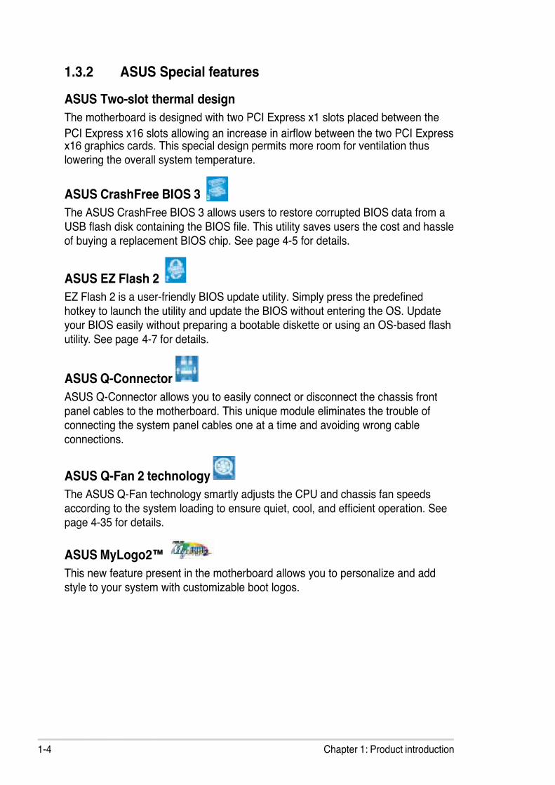
ASUS Two-slot thermal design
The motherboard is designed with two PCI Express x1 slots placed between the
PCI Express x16 slots allowing an increase in airow between the two PCI Expressx16 graphics cards. This special design permits more room for ventilation thuslowering the overall system temperature.
ASUS CrashFree BIOS 3
The ASUS CrashFree BIOS 3 allows users to restore corrupted BIOS data from a
USB ash disk containing the BIOS le. This utility saves users the cost and hassleof buying a replacement BIOS chip. See page 4-5 for details.
ASUS EZ Flash 2
EZ Flash 2 is a user-friendly BIOS update utility. Simply press the predened
hotkey to launch the utility and update the BIOS without entering the OS. Updateyour BIOS easily without preparing a bootable diskette or using an OS-based ash
utility. See page 4-7 for details.
ASUS Q-Connector
ASUS Q-Connector allows you to easily connect or disconnect the chassis front
panel cables to the motherboard. This unique module eliminates the trouble ofconnecting the system panel cables one at a time and avoiding wrong cable
connections.
ASUS Q-Fan 2 technology
The ASUS Q-Fan technology smartly adjusts the CPU and chassis fan speeds
according to the system loading to ensure quiet, cool, and efcient operation. Seepage 4-35 for details.
ASUS MyLogo2™
This new feature present in the motherboard allows you to personalize and add
style to your system with customizable boot logos.

7/27/2019 (E3241)_M2N4-SLI
http://slidepdf.com/reader/full/e3241m2n4-sli 19/138
2Hardwareinformation
This chapter lists the hardware setup
procedures that you have to perform
when installing system components. Itincludes description of the jumpers and
connectors on the motherboard.

7/27/2019 (E3241)_M2N4-SLI
http://slidepdf.com/reader/full/e3241m2n4-sli 20/138
ASUS M2N4-SLI
Chapter summary 22.1 Before you proceed ..................................................................... 2-1
2.2 Motherboard overview ................................................................. 2-2
2.3 Central Processing Unit (CPU) ................................................... 2-5
2.4 System memory ......................................................................... 2-10
2.5 Expansion slots .......................................................................... 2-16
2.6 Jumpers ...................................................................................... 2-19
2.7 Connectors ................................................................................. 2-22
7/27/2019 (E3241)_M2N4-SLI
http://slidepdf.com/reader/full/e3241m2n4-sli 21/138
ASUS M2N4-SLI 2-1
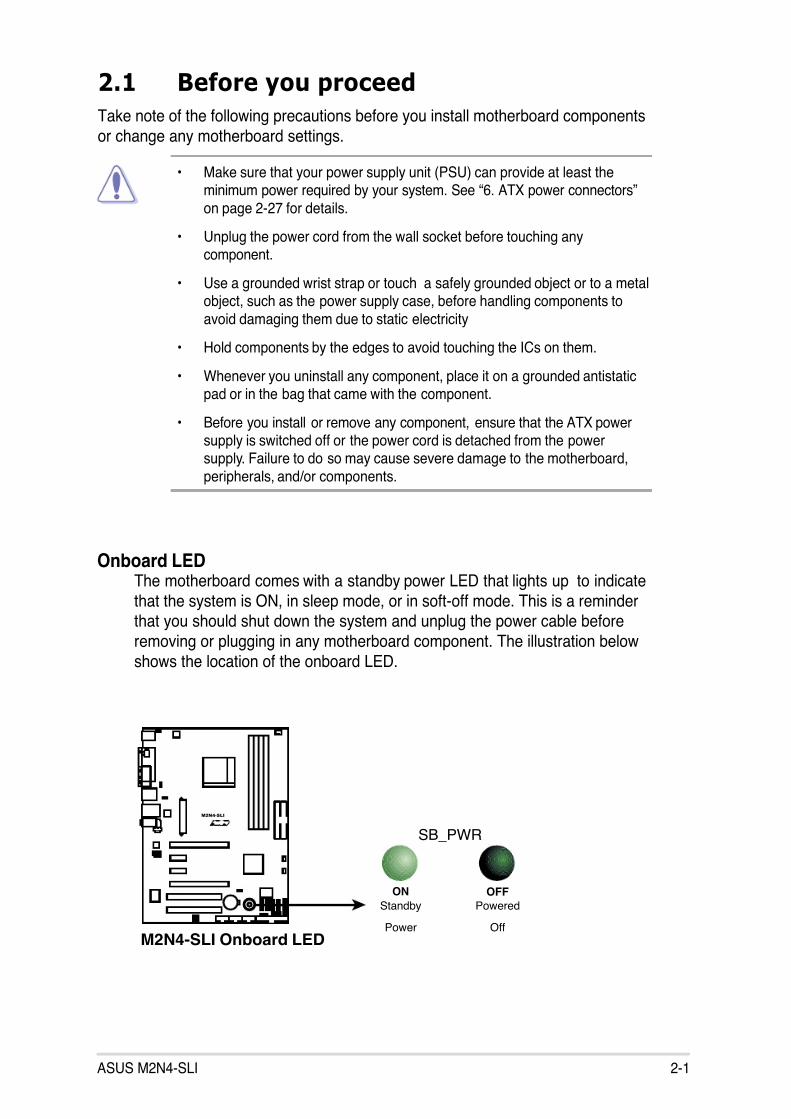
Onboard LEDThe motherboard comes with a standby power LED that lights up to indicate
that the system is ON, in sleep mode, or in soft-off mode. This is a reminderthat you should shut down the system and unplug the power cable before
removing or plugging in any motherboard component. The illustration below
shows the location of the onboard LED.
2.1 Before you proceed
Take note of the following precautions before you install motherboard components
or change any motherboard settings.
• Make sure that your power supply unit (PSU) can provide at least theminimum power required by your system. See “6. ATX power connectors”
on page 2-27 for details.
• Unplug the power cord from the wall socket before touching anycomponent.
• Use a grounded wrist strap or touch a safely grounded object or to a metalobject, such as the power supply case, before handling components to
avoid damaging them due to static electricity
• Hold components by the edges to avoid touching the ICs on them.
• Whenever you uninstall any component, place it on a grounded antistaticpad or in the bag that came with the component.
• Before you install or remove any component, ensure that the ATX powersupply is switched off or the power cord is detached from the powersupply. Failure to do so may cause severe damage to the motherboard,
peripherals, and/or components.
R
M2N4-SLI
M2N4-SLI Onboard LED
SB_PWR
ON
Standby
Power
OFF
Powered
Off

7/27/2019 (E3241)_M2N4-SLI
http://slidepdf.com/reader/full/e3241m2n4-sli 22/138
2-2 Chapter 2: Hardware information
R
M2N4-SLI
2.2 Motherboard overview
Before you install the motherboard, study the conguration of your chassis to
ensure that the motherboard ts into it.
Make sure to unplug the power cord before installing or removing the
motherboard. Failure to do so can cause you physical injury and damagemotherboard components.
Do not overtighten the screws! Doing so can damage the motherboard.
2.2.1 Placement direction
When installing the motherboard, make sure that you place it into the chassis inthe correct orientation. The edge with external ports goes to the rear part of the
chassis as indicated in the image below.
2.2.2 Screw holes
Place six (6) screws into the holes indicated by circles to secure the motherboardto the chassis.
Place this side towardsthe rear of the chassis

7/27/2019 (E3241)_M2N4-SLI
http://slidepdf.com/reader/full/e3241m2n4-sli 23/138
ASUS M2N4-SLI 2-3
2.2.3 Motherboard layout
S o c k e t A M 2
S u p e r I / O
R
M2N4-SLI
CR2032 3VSB_PWRLithium Cell
CMOS Power
ATX12V
KBPWR
23.0cm (9.0in)
3 0 . 5 c m ( 1
2 . 0
i n )
P A N E L
CPU_FANPS/2KBMST: MouseB: Keyboard
P A R A L L E L P O R T
COM1
S P D I F_
O 1
P R I_ I D E
S E C_
I D E
USBPW56USBPW78USBPW910
USB910
FLOPPY
USB78USB56
S A T A 4
S A T A 3
S A T A 2
S A T A 1
CLRTC
CHASSIS
F_PANEL
USBPW34
NVIDIANF500 SLI
C H A_
F A N
P W R_
F A N
USB12
LAN_USB34
FP_AUDIO
SPDIF_OUT
U S B P W 1 2
C D
AUX
PCIEX16_1
PCIEX1_1
PCIEX1_2
PCIEX16_2
PCI1
PCI2
D D R 2 D I M M_
A 1 ( 6 4 b i t , 2
4 0 - p i n m o d u l e )
D D R 2 D I M M_
B 1 ( 6 4 b i t , 2
4 0 - p i n m o d u l e )
D D R 2 D I M M_
A 2 ( 6 4 b i t , 2
4 0 - p i n m o d u l e )
D D R 2 D I M M_
B 2 ( 6 4 b i t , 2
4 0 - p i n m o d u l e )
E A T X P W R
AUDIO
AttansicF1
ALC850
4Mb
BIOS

7/27/2019 (E3241)_M2N4-SLI
http://slidepdf.com/reader/full/e3241m2n4-sli 24/138
2-4 Chapter 2: Hardware information
2.2.4 Layout Contents
1. DDR2 DIMM slots 2-102. PCI slots 2-17
3. PCI Express x1 slot 2-18
4. PCI Express x16 slot 2-18
Rear panel connectors Page
1. PS/2 mouse port (green) 2-21
2. Parallel port 2-21
3. LAN (RJ-45) port 2-21
4. Line In port (light blue) 2-21
5. Line Out port (lime) 2-216. Microphone port (pink) 2-21
7. USB 2.0 ports 3 and 4 2-22
8. USB 2.0 ports 1 and 2 2-22
9. Serial port (COM port) 2-22
10. Coaxial S/PDIF out port 2-22
11. PS/2 keyboard port (purple) 2-22
Jumpers Page
1. CLRTC (3-pin CLRTC1) 2-19
2. USB device wake-up (3-pin USBPW12, USBPW34, USBPW56,USBPW78, USBPW910) 2-20
3. Keyboard Power (3-pin KBPWR) 2-20
1. Floppy disk drive connector (34-1 pin FLOPPY) 2-22
2. IDE connector (40-1 pin PRI_IDE, SEC_IDE) 2-23
3. Serial ATA connectors (7-pin SATA1, SATA2, SATA3, SATA4) 2-24
4. CPU, Chassis, and Power fan connectors (3-pin CPU_FAN, 3-pin PWR_FAN,3-pin CHA_FAN) 2-25
5. USB connectors (10-1 pin USB56, USB78, USB910 2-26
6. ATX power connector (24-pin EATXPWR1, 4-pin ATX12V) 2-27
7. Internal audio connectors (4-pin CD, AUX) 2-28
8. Front panel audio connector (10-1 pin FP_AUDIO) 2-28
9. System panel connector (20-pin PANEL) 2-29
Internal connectors Page
Slots Page

7/27/2019 (E3241)_M2N4-SLI
http://slidepdf.com/reader/full/e3241m2n4-sli 25/138
ASUS M2N4-SLI 2-5
2.3.1 Installing the CPU
To install a CPU:
1. Locate the CPU socket on the motherboard.
Make sure that the socket lever is lifted up to a 90º angle; otherwise, the CPUwill not t in completely.
2. Unlock the socket by pressing thelever sideways, then lift it up to a
90º angle.
2.3 Central Processing Unit (CPU)
The motherboard comes with a 940-pin AM2 socket designed for the AMD Athlon™
64 X2/AMD Athlon™ 64 FX/AMD Athlon™ 64 and AMD Sempron™ processors.
Socket lever
Make sure you use a CPU is designed for the AM2 socket. The CPU ts inonly one correct orientation. DO NOT force the CPU into the socket to preventbending the connectors on the socket and damaging the CPU!
R
M2N4-SLI
M2N4-SLI CPU Socket AM2

7/27/2019 (E3241)_M2N4-SLI
http://slidepdf.com/reader/full/e3241m2n4-sli 26/138
2-6 Chapter 2: Hardware information
3. Position the CPU above the socket
such that the CPU corner with the
gold triangle matches the socketcorner with a small triangle.
4. Carefully insert the CPU into the
socket until it ts in place.
5. When the CPU is in place, push
down the socket lever to secure the
CPU. The lever clicks on the side tabto indicate that it is locked.
6. Install a CPU heatsink and fan
following the instructions that came
with the heatsink package.
Gold triangle
Small triangle

7/27/2019 (E3241)_M2N4-SLI
http://slidepdf.com/reader/full/e3241m2n4-sli 27/138
ASUS M2N4-SLI 2-7
2.3.2 Installing the heatsink and fan
The the AMD Athlon™ FX, AMD Athlon 64™, AMD Sempron™ or AMD Athlon™
X2 processor require a specially designed heatsink and fan assembly to ensure
optimum thermal condition and performance.
Follow these steps to install the CPU heatsink and fan.
1. Place the heatsink on top of the installed CPU, making sure that the heatsink
ts properly on the retention module base.
Retention Module Base
CPU Heatsink
CPU Fan
Retention bracket lockRetention bracket
• The retention module base is already installed on the motherboardupon purchase.
• You do not have to remove the retention module base wheninstalling the CPU or installing other motherboard components.
• If you purchased a separate CPU heatsink and fan assembly, makesure that a Thermal Interface Material is properly applied to the CPUheatsink or CPU before you install the heatsink and fan assembly.
Your boxed CPU heatsink and fan assembly should come with installationinstructions for the CPU, heatsink, and the retention mechanism. If theinstructions in this section do not match the CPU documentation, follow thelatter.
Make sure that you use only qualied heatsink and fan assembly.

7/27/2019 (E3241)_M2N4-SLI
http://slidepdf.com/reader/full/e3241m2n4-sli 28/138
2-8 Chapter 2: Hardware information
2. Attach one end of the retention bracket to the retention module base.
3. Align the other end of the retention bracket (near the retention bracket lock)
to the retention module base. A clicking sound denotes that the retentionbracket is in place.
4. Push down the retention bracket lock on the retention mechanism to securethe heatsink and fan to the module base.
Make sure that the fan andheatsink assembly perfectly tsthe retention mechanism module
base, otherwise you cannot snapthe retention bracket in place.

7/27/2019 (E3241)_M2N4-SLI
http://slidepdf.com/reader/full/e3241m2n4-sli 29/138
ASUS M2N4-SLI 2-9
5. When the fan and heatsink assembly is in place, connect the CPU fan cable
to the connector on the motherboard labeled CPU_FAN.
Do not forget to connect the CPU fan connector! Hardware monitoring errors
can occur if you fail to plug this connector.
R
M2N4-SLI
M2N4-SLI CPU Fan Connectors
G N D
C P U F A N P W R
C P U F A N I N
C P U F A N P W M
CPU_FAN
7/27/2019 (E3241)_M2N4-SLI
http://slidepdf.com/reader/full/e3241m2n4-sli 30/138
2-10 Chapter 2: Hardware information
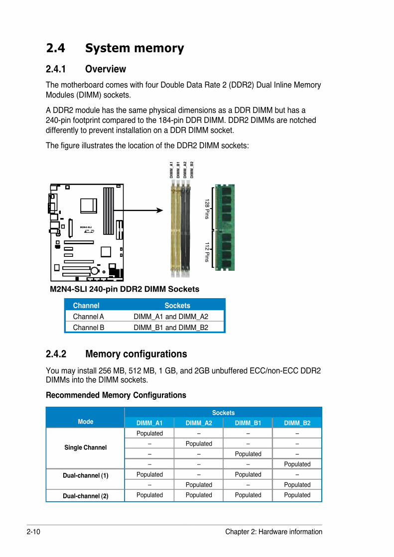
2.4 System memory
2.4.1 Overview
The motherboard comes with four Double Data Rate 2 (DDR2) Dual Inline Memory
Modules (DIMM) sockets.
A DDR2 module has the same physical dimensions as a DDR DIMM but has a240-pin footprint compared to the 184-pin DDR DIMM. DDR2 DIMMs are notched
differently to prevent installation on a DDR DIMM socket.
The gure illustrates the location of the DDR2 DIMM sockets:
Channel Sockets
Channel A DIMM_A1 and DIMM_A2
Channel B DIMM_B1 and DIMM_B2
2.4.2 Memory congurations
You may install 256 MB, 512 MB, 1 GB, and 2GB unbuffered ECC/non-ECC DDR2DIMMs into the DIMM sockets.
Recommended Memory Congurations
Mode
Sockets
DIMM_A1 DIMM_A2 DIMM_B1 DIMM_B2
Single Channel
Populated – – –
– Populated – –
– – Populated –
– – – Populated
Dual-channel (1) Populated – Populated –
– Populated – Populated
Dual-channel (2) Populated Populated Populated Populated
R
M2N4-SLI
M2N4-SLI 240-pin DDR2 DIMM Sockets
D I M M_
B 1
D I M M_
A 2
D I M M_
B 2
D I M M_
A 1
1 1 2
P i n s
1 2 8
P i n s

7/27/2019 (E3241)_M2N4-SLI
http://slidepdf.com/reader/full/e3241m2n4-sli 31/138
ASUS M2N4-SLI 2-11
Important notice on installing Windows® XP 32-bit version
If you install Windows® XP 32-bit version Operating System (OS), the limitationof this OS version is that it may reserve a certain amount of memory space forsystem devices. We recommend that you install less than 3 GB system memoryif you would like to work under Windows® XP 32-bit version OS. The excessmemory installation will not cause any usage problem, but it will not give users
the benet of manipulating this excess memory space.
Visit the ASUS FAQ site for furtherexplanation:http://support.asus.com/faq/faq.
aspx?SLanguage=en-usUnder General Search, make theselections as shown, then click Search.Click the article titled “4GB memory installed but less memory sizedetected.”
You also may check the URLs below for third party comments on this issue:http://dlsvr01.asus.com/pub/ASUS/mb/4GB_Rev1.pdf http://www.intel.com/support/motherboards/server/sb/cs-016594.htm
* For dual-channel memory conguration (2), you may: • install identical DIMMs in all four sockets OR• install an identical DIMM pair in DIMM_A1 and DIMM_B1 (yellow
sockets) and another identical DIMM pair in DIMM_A2 andDIMM_B2 (black sockets)
* Always use identical DDR2 DIMM pairs for dual-channel model. Foroptimum compatibility, we recommend that you obtain memory modulesfrom the same vendor. Visit the ASUS website (www.asus.com) for thelatest Qualied Vendors List.
This motherboard can support 8 GB physical memory on the operating systemslisted below. You may install a maximum of 2 GB DIMMs on each slot.
32-bit 64-bit
Windows® 2000 Advanced Server
Windows® Server 2003 EnterpriseEdition
Windows® Server 2003 Standardx64 Edition
Windows® XP Professional x64Edition
Windows® Server 2003 Enterprisex64 Edition

7/27/2019 (E3241)_M2N4-SLI
http://slidepdf.com/reader/full/e3241m2n4-sli 32/138
2-12 Chapter 2: Hardware information
Qualied Vendors List DDR2-533
256MB KINGSTON E5116AF-5C-E SS KVR533D2N4/256 V V
1024MB KINGSTON 5YDIID9GCT DS KVR533D2N4/1G V V V
512MB Qimonda HYB18T512800AC37 SS HYS64T64000GU-3.7-A V V V
256MB Qimonda HYB18T512160AF-3.7 SS HYS64T32000HU-3.7-A V V V
512MB Qimonda HYB18T512800AF37 SS HYS64T64000HU-3.7-A V V
256MB Qimonda HYB18T5121608BF-3.7 SS HYS64T32000HU-3.7-B V V V
512MB Qimonda HYB18T512800BF37 SS HYS64T64000HU-3.7-B V V V
1024MB Qimonda HYB18T512800BF37 DS HYS64T128020HU-3.7-B V
512MB Hynix HY5PS12821F-C4 SS HYMP564U648-C4 V
1024MB Hynix HY5PS12821F-C4 DS HYMP512U648-C4 V V V
1024MB Hynix HY5PS12821F-C4(ECC) DS HYMP512U728-C4 V V
512MB Hynix HY5PS12821FP-C4(ECC) SS HYMP564U728-C4 V V
512MB Hynix HY5PS12821AFP-C3 SS HYMP564U64AP8-C3 V V V
512MB ELPIDA E5108AB-5C-E SS EBE51UD8ABFA-5C-E V V V
512MB KINGMAX E5108AE-5C-E SS KLBC28F-A8EB4 V
512MB KINGMAX KKEA88E4AAK-37 SS KLBC28F-A8KE4 V V V
1024MB KINGMAX 5MB22D9DCN DS KLBD48F-A8ME4 V V V
Size Vendor Model Side(s) ComponentDIMM support
A* B* C*

7/27/2019 (E3241)_M2N4-SLI
http://slidepdf.com/reader/full/e3241m2n4-sli 33/138
ASUS M2N4-SLI 2-13
Qualied Vendors List DDR2-667
512MB KINGSTON E5108AE-6E-E SS KVR667D2N5/512 V V V
1024MB KINGSTON E5108AE-6E-E DS KVR667D2N5/1G V V
512MB KINGSTON E5108AE-6E-E SS KVR667D2E5/512 V V V
256MB KINGSTON HYB18T256800AF3 SS KVR667D2N5/256 V V V
256MB SAMSUNG K4T56083QF-ZCE6 SS M378T3253FZ0-CE6 V V V
256MB SAMSUNG K4T51163QC-ZCE6 SS M378T3354CZ0-CE6 V V V
512MB SAMSUNG ZCE6K4T51083QC SS M378T6553CZ0-CE6 V V V
1024MB SAMSUNG ZCE6K4T51083QC DS M378T2953CZ0-CE6 V V V
512MB MICRON 4VB41D9CZM DS MT16HTF6464AY-667B4 V V V
256MB Inneon HYB18T512160AF-3S SS HYS64T32000HU-3S-A V V V
512MB Inneon HYB18T512800AF3S SS HYS64T64000HU-3S-A V V V
1024MB Inneon HYB18T512800AF3S DS HYS64T128020HU-3S-A V V V
256MB Inneon HYB18T256800AF3S(ECC) SS HYS72T32000HU-3S-A V V V
512MB Inneon HYB18T512800AF3S(ECC) SS HYS72T64000HU-3S-A V V V
1024MB Inneon HYB18T512800AF3S(ECC) DS HYS72T128020HU-3S-A V V V
512MB Inneon HYB18T512800BF3S(ECC) SS HYS72T64000HU-3S-B V V V
1024MB Inneon HYB18T512800BF3S(ECC) DS HYS72T128020HU-3S-B V V V
256MB Inneon HYB18T512160BF-3S SS HYS64T32000HU-3S-B V V
512MB Inneon HYB18T512800BF3S SS HYS64T64000HU-3S-B V V V
1024MB Inneon HYB18T512800BF3S DS HYS64T128020HU-3S-B V V V
512MB Hynix HY5PS12821AFP-Y5 SS HYMP564U64AP8-Y5 V V V
1024MB Hynix HY5PS12821AFP-Y5 DS HYMP512U64AP8-Y5 V V V
512MB Hynix HY5PS12821AFP-Y5(ECC) SS HYMP564U72AP8-Y5 V V V
1024MB Hynix HY5PS12821AFP-Y5(ECC) DS HYMP512U72AP8-Y5 V V V
512MB Hynix HY5PS12821AFP-Y4 SS HYMP564U64AP8-Y4 V V V
1024MB Hynix HY5PS12821AFP-Y4 DS HYMP512U64AP8-Y4 V V V
512MB Hynix HY5PS12821AFP-Y4(ECC) SS HYMP564U72AP8-Y4 V V V
1024MB Hynix HY5PS12821AFP-Y4(ECC) DS HYMP512U72AP8-Y4 V V V256MB ELPIDA E2508AB-6E-E SS EBE25UC8ABFA-6E-E V V V
512MB ELPIDA E5108AE-6E-E SS EBE51UD8AEFA-6E-E V V V
1024MB ELPIDA Engineering Sample DS EBE11UD8AEFA-6E-E V V
512MB crucial Heat-Sink Package SS BL6464AA663.8FD V V V
1024MB crucial Heat-Sink Package DS BL12864AA663.16FD V V V
512MB A-DATA E5108AE-6E-E SS M20EL5G3H3160B1C0Z V V V
512MB A-DATA AD29608A8B-3EG SS M20AD5Q3H3163J1C52 V V V
512MB Transcend E5108AE-6E-E SS TS64MLQ64V6J V
1024MB Transcend E5108AE-6E-E DS TS128MLQ64V6J V V V
512MB Transcend J12Q3AB-6 SS JM367Q643A-6 V V
Size Vendor Model Side(s) Component DIMM support A* B* C*

7/27/2019 (E3241)_M2N4-SLI
http://slidepdf.com/reader/full/e3241m2n4-sli 34/138
2-14 Chapter 2: Hardware information
Qualied Vendors List DDR2-800
Side(s): SS - Single-sided DS - Double-sided
DIMM Support:
A - Supports one module inserted in any slot for a single-channel memory
conguration.B - Supports one pair of modules inserted into either the yellow slots or the black
slots as one pair of dual-channel memory conguration.
C - Supports two pairs of modules inserted into the yellow and black slots as two
pairs of dual-channel memory conguration.
Visit the ASUS website (www.asus.com) for the latest memory Qualied VendorList (QVL).
512MB KINGSTON Heat-Sink Package SS KHX6400D2/512 V V
512MB KINGSTON K4T51083QC SS KVR800D2N5/512 V V V
1024MB KINGSTON K4T51083QC DS KVR800D2N5/1G V V V
512MB SAMSUNG EDD339XX SS M378T6553CZ3-CE7 V V V
512MB Inneon HYB18T256800AF25 DS HYS64T64520HU-2.5-A V V V
512MB Hynix HY5PS12821BFP-S5 SS HYMP564U64BP8-S5 V V V
1024MB Hynix HY5PS12821BFP-S5 DS HYMP512U64BP8-S5 V V
512MB MICRON 5JAIIZ9DQQ SS MT8HTF6464AY-80EA3 V V V
1024MB MICRON 5JAIIZ9DQQ DS MT16HTF12864AY-80EA3 V V V
512MB MICRON 5ZD22D9GKX SS MT8HTF6464AY-80ED4 V V V
1024MB MICRON 5ZD22D9GKX DS MT16HTF12864AY-80ED4 V V V
512MB MICRON 6CD22D9GKX SS MT8HTF6464AY-80ED4 V V V
1024MB MICRON 6CD22D9GKX DS MT16HTF12864AY-80ED4 V V V
1024MB CORSAIR Heat-Sink Package DS CM2X1024-6400PRO V V V
1024MB CORSAIR Heat-Sink Package DS CM2X1024-6400C4 V V V
256MB A-DATA E2508AB-GE-E SS M20EL6F3G3160A1D0Z V V V
512MB A-DATA N/A SS M2OAD6G3H3160J1E52 V
512MB A-DATA AD29608A8A-25EG SS M20AD6G3H3160I1E5E V
512MB Crucial Heat-Sink Package SS BL6464AA804.8FA V V V
1024MB Crucial Heat-Sink Package DS BL12864AA804.16FA V V V
1024MB Crucial Heat-Sink Package DS BL12864AA804.16FD V V
256MB Apacer E2508AB-GE-E SS 78.81091.420 V
Size Vendor Model Side(s) ComponentDIMM support
A* B* C*

7/27/2019 (E3241)_M2N4-SLI
http://slidepdf.com/reader/full/e3241m2n4-sli 35/138
ASUS M2N4-SLI 2-15
2.4.3 Installing a DIMM
Unplug the power supply before adding or removing DIMMs or othersystem components. Failure to do so can cause severe damage to both the
motherboard and the components.
To install a DIMM:
1. Unlock a DIMM socket by
pressing the retaining clipsoutward.
2. Align a DIMM on the socketsuch that the notch on the DIMM
matches the break on the socket.3. Firmly insert the DIMM into the
socket until the retaining clips
snap back in place and theDIMM is properly seated.
2.4.4 Removing a DIMM
To remove a DIMM:
1. Simultaneously press the retainingclips outward to unlock the DIMM.
2. Remove the DIMM from the socket.
• A DDR2 DIMM is keyed with a notch so that it ts in only one direction. Donot force a DIMM into a socket to avoid damaging the DIMM.
• The DDR2 DIMM sockets do not support DDR DIMMs. DO not install DDRDIMMs to the DDR2 DIMM sockets.
Support the DIMM lightly withyour ngers when pressing theretaining clips. The DIMM mightget damaged when it ips outwith extra force.
1
2
1 DDR2 DIMM notch
Unlocked retaining clip
DDR2 DIMM notch
1
2
3

7/27/2019 (E3241)_M2N4-SLI
http://slidepdf.com/reader/full/e3241m2n4-sli 36/138
2-16 Chapter 2: Hardware information
2.5 Expansion slots
In the future, you may need to install expansion cards. The following sub-sections
describe the slots and the expansion cards that they support.
2.5.1 Installing an expansion card
To install an expansion card:
1. Before installing the expansion card, read the documentation that came withit and make the necessary hardware settings for the card.
2. Remove the system unit cover (if your motherboard is already installed in achassis).
3. Remove the bracket opposite the slot that you intend to use. Keep the screwfor later use.
4. Align the card connector with the slot and press rmly until the card is
completely seated on the slot.
5. Secure the card to the chassis with the screw you removed earlier.
6. Replace the system cover.
2.5.2 Conguring an expansion card
After installing the expansion card, congure the it by adjusting the software
settings.
1. Turn on the system and change the necessary BIOS settings, if any. See
Chapter 4 for information on BIOS setup.
2. Assign an IRQ to the card. Refer to the tables on the next page.
3. Install the software drivers for the expansion card.
Make sure to unplug the power cord before adding or removing expansioncards. Failure to do so may cause you physical injury and damage motherboardcomponents.
When using PCI cards on shared slots, ensure that the drivers support “ShareIRQ” or that the cards do not need IRQ assignments; otherwise, conicts willarise between the two PCI groups, making the system unstable and the cardinoperable.
7/27/2019 (E3241)_M2N4-SLI
http://slidepdf.com/reader/full/e3241m2n4-sli 37/138
ASUS M2N4-SLI 2-17
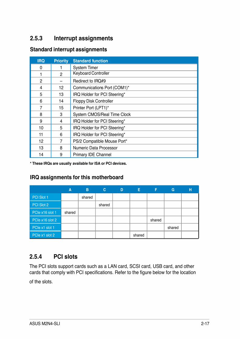
2.5.3 Interrupt assignments
Standard interrupt assignments
* These IRQs are usually available for ISA or PCI devices.
IRQ Priority Standard function
0 1 System Timer
1 2 Keyboard Controller
2 – Redirect to IRQ#9
4 12 Communications Port (COM1)*
5 13 IRQ Holder for PCI Steering*
6 14 Floppy Disk Controller
7 15 Printer Port (LPT1)*
8 3 System CMOS/Real Time Clock
9 4 IRQ Holder for PCI Steering*
10 5 IRQ Holder for PCI Steering*
11 6 IRQ Holder for PCI Steering*
12 7 PS/2 Compatible Mouse Port*
13 8 Numeric Data Processor
14 9 Primary IDE Channel
A B C D E F G H
PCI Slot 1 shared
PCI Slot 2 shared
PCIe x16 slot 1 shared
PCIe x16 slot 2 shared
PCIe x1 slot 1 shared
PCIe x1 slot 2 shared
IRQ assignments for this motherboard
2.5.4 PCI slots
The PCI slots support cards such as a LAN card, SCSI card, USB card, and other
cards that comply with PCI specications. Refer to the gure below for the location
of the slots.

7/27/2019 (E3241)_M2N4-SLI
http://slidepdf.com/reader/full/e3241m2n4-sli 38/138
2-18 Chapter 2: Hardware information
• In single card mode, we recommend that you use the blue PCI Expressx16 (PCIEX16_1) slot.
• Due to chipset limitation, the black PCI Express x16 (PCIEX16_2) slot canonly operate at x8 speed.
• Connect a rear chassis fan to the chassis (CHA_FAN1 or CHA_FAN2)
connector when using two graphics cards for better thermal environment.See page 2-25 for details.
• We recommend that you provide sufcient power when running NVIDIA® SLI™ mode. See pages 2-27 and 2-29 for details.
PCI Express x 16 black slot(at x8 speed)
PCI Express x16 blue slot
(at x16 speed)
PCI slots
PCI Express x1 slot
2.5.5 PCI Express x1 slot
This motherboard supports PCI Express x1 network cards, SCSI cards and other
cards that comply with the PCI Express specications. Refer to the gure below for
the location of the slot.
2.5.6 PCI Express x16 slots
This motherboard supports PCI Express x16 graphics cards that comply with the
PCI Express specications. Refer to the gure below for the location of the slots.
Recommended PCI Express x16 congurations
Mode
PCIEX16_1 (Blue) slot PCIE16_2 (Black) slot
Card type Speed Card type Speed
Non-SLI mode PCIe x16 graphics card x16 NA
PCIe x16 graphics card x8 PCIe x16 graphics card x8
PCIe x16 graphics card x8 Other PCIe devices x8, x4, x1
Dual graphics cardin SLI Mode
Two identical NVIDIA® SLI™ Edition graphics cards at x8, x8 speed

7/27/2019 (E3241)_M2N4-SLI
http://slidepdf.com/reader/full/e3241m2n4-sli 39/138
ASUS M2N4-SLI 2-19
2.6 Jumpers
1. Clear RTC RAM (CLRTC)
This jumper allows you to clear the Real Time Clock (RTC) RAM in
CMOS. You can clear the CMOS memory of date, time, and system setupparameters by erasing the CMOS RTC RAM data. The onboard buttoncell battery powers the RAM data in CMOS, which include system setup
information such as system passwords.
To erase the RTC RAM:
1. Turn OFF the computer and unplug the power cord.
2. Remove the onboard battery.
3. Move the jumper cap from pins 1-2 (default) to pins 2-3. Keep the cap on pins2-3 for about 5~10 seconds, then move the cap back to pins 1-2.
4. Re-install the battery.
5. Plug the power cord and turn ON the computer.
6. Hold down the <Del> key during the boot process and enter BIOS setup tore-enter data.
Except when clearing the RTC RAM, never remove the cap on CLRTC jumper
default position. Removing the cap will cause system boot failure!
You do not need to clear the RTC when the system hangs due to overclocking.For system failure due to overclocking, use the C.P.R. (CPU Parameter Recall)
feature. Shut down and reboot the system so the BIOS can automatically resetparameter settings to default values.
R
M2N4-SLI
M2N4-SLI Clear RTC RAM
CLRTC
Normal Clear CMOS
(Default)
2 31 2

7/27/2019 (E3241)_M2N4-SLI
http://slidepdf.com/reader/full/e3241m2n4-sli 40/138
2-20 Chapter 2: Hardware information
2. USB device wake-up (3-pin USBPW12, USBPW34, USBPW56, USBPW78,USBPW910)
Set these jumpers to +5V to wake up the computer from S1 sleep mode
(CPU stopped, DRAM refreshed, system running in low power mode) using
the connected USB devices. Set to +5VSB to wake up from S3 and S4 sleepmodes (no power to CPU, DRAM in slow refresh, power supply in reduced
power mode).
• The USB device wake-up feature requires a power supply that can provide500mA on the +5VSB lead for each USB port; otherwise, the system wouldnot power up.
• The total current consumed must NOT exceed the power supply capability(+5VSB whether under normal condition or in sleep mode.
R
M2N4-SLI
M2N4-SLI USB device Wake up
USBPW12
(Default)+5V +5VSB
2
3
1
2 1 2
USBPW34
+5V
(Default) +5VSB
32
3221
+5V(Default)+5VSB
USBPW56USBPW78USBPW910
3. Keyboard power (3-pin KBPWR)
This jumper allows you to enable or disable the keyboard wake-up feature.Set this jumper to pins 2-3 (+5VSB) if you wish to wake up the computer
when you press a key on the keyboard (the default value is [Disabled]). This
feature requires an ATX power supply that can supply at least 1A on the
+5VSB lead, and a corresponding setting in the BIOS (see section 4.5.3 APMConguration).
R
M2N4-SLI
M2N4-SLI Keyboard Power Setting
(Default)+5V +5VSB
KBPWR
2 31 2

7/27/2019 (E3241)_M2N4-SLI
http://slidepdf.com/reader/full/e3241m2n4-sli 41/138
ASUS M2N4-SLI 2-21
2.7 Connectors
2.7.1 Rear panel connectors
1. PS/2 mouse port (green). This port is for a PS/2 mouse.
2. Parallel port. This 25-pin port connects a parallel printer, a scanner, or otherdevices.
3. LAN (RJ-45) port. Supported by the NVIDIA® nForce™ 500 Gigabit MAC with
external Attansic PHY, this port allows Gigabit connection to a Local Area
Network (LAN) through a network hub. Refer to the table below for the LAN
port LED indications.
SPEEDLED
ACT/LINKLED
LAN port
LAN port LED indications
4. Line In port (light blue). This port connects the tape, CD, DVD player, or otheraudio sources.
5. Line Out port (lime). This port connects a headphone or a speaker. In 4-
channel, 6-channel, and 8-channel conguration, the function of this port
becomes Front Speaker Out.
6. Microphone port (pink). This port connects a microphone.
ACT/LINK LED SPEED LED
Status Description Status Description
OFF No link OFF 10 Mbps connection
GREEN Linked ORANGE 100 Mbps connection
BLINKING Data activity GREEN 1 Gbps connection
Refer to the audio conguration table below for the function of the audio ports in
2, 4, or 6-channel conguration.
1
11
4
5
6
7
2 3
10 89

7/27/2019 (E3241)_M2N4-SLI
http://slidepdf.com/reader/full/e3241m2n4-sli 42/138
2-22 Chapter 2: Hardware information
7. USB 2.0 ports 3 and 4. These two 4-pin Universal Serial Bus (USB) ports are
available for connecting USB 2.0 devices.
8. USB 2.0 ports 1 and 2. These two 4-pin Universal Serial Bus (USB) ports areavailable for connecting USB 2.0 devices.
9. Serial port (COM port). This 9-pin COM port is for pointing devices and otherserial devices.
10. Coaxial S/PDIF Out port. This port connects an external audio output device
via a coaxial S/PDIF cable.
11. PS/2 keyboard port (purple). This port is for a PS/2 keyboard.
Audio 2, 4, or 6-channel conguration
Light Blue Line In Rear Speaker Out Rear Speaker Out
Lime Line Out Front Speaker Out Front Speaker Out
Pink Mic In Mic In Center/Subwoofe
Port Headset 4-channel 6-channel
2-channel
2.7.2 Internal connectors
1. Floppy disk drive connector (34-1 pin FLOPPY)
This connector is for the provided oppy disk drive (FDD) signal cable. Insert
one end of the cable to this connector, then connect the other end to the
signal connector at the back of the oppy disk drive.
The Pin 5 on the connector is removed to prevent incorrect cable connectionwhen using an FDD cable with a covered Pin 5.
R
M2N4-SLI
M2N4-SLI Floppy Disk Drive Connector
P I N
1
NOTE: Orient the red markings onthe floppy ribbon cable to PIN 1.
FLOPPY

7/27/2019 (E3241)_M2N4-SLI
http://slidepdf.com/reader/full/e3241m2n4-sli 43/138
ASUS M2N4-SLI 2-23
2. IDE connector (40-1 pin PRI_IDE, SEC_IDE)
The onboard IDE connectors are for the Ultra DMA 133/100/66 signal cable.There are three connectors on each Ultra DMA 133/100/66 signal cable:
blue, black, and gray. Connect the blue connector to the motherboard’s IDEconnector, then select one of the following modes to congure your device.
Drive jumper setting Mode ofdevice(s)
Cable connector
Single device Cable-Select or Master - Black
Two devices Cable-Select Master Black
Slave Gray
Master Master Black or gray
Slave Slave
• Pin 20 on the IDE connector is removed to match the covered hole on theUltra DMA cable connector. This prevents incorrect insertion when youconnect the IDE cable.
• Use the 80-conductor IDE cable for Ultra DMA 100/66 IDE devices.
R
M2N4-SLI
M2N4-SLI IDE Connectors
P R I_ I D E
S E C_ I D
E
NOTE: Orient the red markings(usually zigzag) on the IDribbon cable to PIN 1.
P I N 1
P I N 1
If any device jumper is set as “Cable-Select,” make sure all other device jumpers have the same setting.

7/27/2019 (E3241)_M2N4-SLI
http://slidepdf.com/reader/full/e3241m2n4-sli 44/138
2-24 Chapter 2: Hardware information
3. Serial ATA connectors (7-pin SATA1, SATA2, SATA3, SATA4)
These connectors are for the Serial ATA signal cables for Serial ATA 3.0
Gb/s hard disk and optical disk drives. The Serial ATA 3.0 Gb/s is backwardcompatible with Serial ATA 1.5 Gb/s specication.
If you installed Serial ATA hard disk drives, you can create a RAID 0, RAID
1, RAID 0+1, RAID 5, or JBOD conguration through the onboard NVIDIA®
MediaShield™ controller.
The RAID function of these connectors is set to [Disabled] by default. If youintend to create a Serial ATA RAID set using these connectors, enable the RAIDEnabled item in the SATA Conguration sub-menu in the BIOS. See section“4.4.7 Onboard Device Conguration” for details.
Connect the right-angle side
of the SATA signal cable to theSATA device or you may connectthe right-angle side of the SATAcable to the onboard SATA portto avoid placement conict withhuge graphics cards.
right angle side
R
M2N4-SLI
M2N4-SLI SATA Connectors GNDRSATA_TXP1RSATA_TXN1GNDRSATA_RXP1RSATA_RXN1GND
GNDRSATA_TXP2RSATA_TXN2GNDRSATA_RXP2RSATA_RXN2GND
GNDRSATA_TXP3RSATA_TXN3GNDRSATA_RXP3RSATA_RXN3GND
GNDRSATA_TXP4RSATA_TXN4GNDRSATA_RXP4RSATA_RXN4GND
SATA1 SATA4SATA3SATA2

7/27/2019 (E3241)_M2N4-SLI
http://slidepdf.com/reader/full/e3241m2n4-sli 45/138
ASUS M2N4-SLI 2-25
4. CPU, Chassis, and Power fan connectors (3-pin CPU_FAN, 3-pinPWR_FAN, 3-pin CHA_FAN)
The fan connectors support cooling fans of 350mA~2000mA (24 W max.) or
a total of 1A~3.48A (41.76 W max.) at +12V. Connect the fan cables to the
fan connectors on the motherboard, making sure that the black wire of eachcable matches the ground pin of the connector.
• Do not forget to connect the fan cables to the fan connectors. Lackof sufcient air ow inside the system may damage the motherboardcomponents. These are not jumpers! DO NOT place jumper caps on the fanconnectors!
• The ASUS Q-Fan function is supported using the CPU Fan (CPU_FAN) andChassis Fan (CHA_FAN) connectors only.
R
M2N4-SLI
M2N4-SLI Fan Connectors
G N D
C P U F A N P W R
C P U F A N I N
C P U F A N P W M
CPU_FAN
CHA_FAN
GND
Rotation+12V
PWR_FAN
GND
Rotation+12V

7/27/2019 (E3241)_M2N4-SLI
http://slidepdf.com/reader/full/e3241m2n4-sli 46/138
2-26 Chapter 2: Hardware information
5. USB connectors (10-1 pin USB56, USB78, USB910)
These connectors are for USB 2.0 ports. Connect the USB module cable
to any of these connectors, then install the module to a slot opening at theback of the system chassis. These USB connectors comply with USB 2.0
specication that supports up to 480 Mbps connection speed.
R
M2N4-SLI
M2N4-SLI USB 2.0 Connectors
G N D
N C
G N D
USB78 U S B + 5
V
U S B_ P
8 -
U S B_ P
8 +
U S B + 5 V
U S B_
P 7 -
U S B_
P 7 +
1
USB56 U S B + 5 V
U S B_ P
6
U S B_ P
6
G N D
N C
U S B + 5 V
U S B_
P 5 -
U S B_
P 5 +
G N D
- +
1 1
U S B + 5 V
U S B_ P 1
0 -
U S B_ P 1
0 +
U S B + 5 V
U S B_
P 9 -
U S B_
P 9 +
G N D
G N D
USB910
N C
Never connect a 1394 cable to the USB connectors. Doing so will damage themotherboard!
The USB module is purchased separately.

7/27/2019 (E3241)_M2N4-SLI
http://slidepdf.com/reader/full/e3241m2n4-sli 47/138
ASUS M2N4-SLI 2-27
R
M2N4-SLI
M2N4-SLI ATX Power Connector
+3 Volts
+3 Volts
Ground
+5 Volts
+5 Volts
Ground
Ground
Power OK+5V Standby
+12 Volts
-5 Volts
+5 Volts
+3 Volts
-12 Volts
Ground
Ground
Ground
PSON#
Ground
+5 Volts
+12 Volts
+3 Volts
+5 Volts
Ground
EATXPWR
6. ATX power connectors (24-pin EATXPWR1,4-pin ATX12V)
These connectors are for an ATX power supply plugs. The power supply
plugs are designed to t these connectors in only one orientation. Find theproper orientation and push down rmly until the connectors completely t.
• Do not forget to connect the 4-pin ATX +12 V power plug; otherwise, thesystem will not boot.
• Use of a PSU with a higher power output is recommended whenconguring a system with more power-consuming devices. The systemmay become unstable or may not boot up if the power is inadequate.
• Make sure that your power supply unit (PSU) can provide at least the
minimum power required by your system.

7/27/2019 (E3241)_M2N4-SLI
http://slidepdf.com/reader/full/e3241m2n4-sli 48/138
2-28 Chapter 2: Hardware information
7. Internal audio connectors (4-pin CD, AUX)
These connectors allow you to receive stereo audio input from sound
sources such as a CD-ROM, TV-tuner, or MPEG card.
8. Front panel audio connector (10-1 pin FP_AUDIO)
This connector is for a chassis-mounted front panel audio I/O module that
supports either HD or legacy AC ‘97 audio standard. Connect one end of thefront panel audio I/O module cable to this connector.
R
M2N4-SLI
M2N4-SLI Internal Audio Connectors
AUX(White)
R i g h t A u d i o C h a n n e l
L e f t A u d i o C h a n n e l
G r o u n d
G r o u n d
CD(black)
Right Audio Channel
Left Audio Channel
Ground
Ground
R
M2N4-SLI
M2N4-SLI Front panel audio connector
FP_AUDIO
L i n e o u t_ L
B L I N E
_ O U T_
L
M I C 2
N C
M I C P W R
B L I N E
_ O U T_
R
A G N D
+ 5 V A

7/27/2019 (E3241)_M2N4-SLI
http://slidepdf.com/reader/full/e3241m2n4-sli 49/138
ASUS M2N4-SLI 2-29
9. System panel connector (20-pin PANEL)
This connector supports several chassis-mounted functions.
R
M2N4-SLI
M2N4-SLI System Panel Connector
* Requires an ATX power supply
PANEL
P L E D -
P W R
+ 5 V
S p e a k e r
G r o u n d
RESET
G r o u n d
R e s e t
G r o u n d
G r o u n d
PWRSW
P L E D +
I D E_
L E D -
I D E_
L E D +
IDE_LED
PLED SPEAKER
• System power LED (2-pin PLED)
This 2-pin connector is for the system power LED. Connect the chassispower LED cable to this connector. The system power LED lights up when
you turn on the system power, and blinks when the system is in sleep mode.
• Hard disk drive activity LED (2-pin IDE_LED)
This 2-pin connector is for the HDD Activity LED. Connect the HDD Activity
LED cable to this connector. The IDE LED lights up or ashes when data is
read from or written to the HDD.
• System warning speaker (4-pin SPEAKER)
This 4-pin connector is for the chassis-mounted system warning speaker. Thespeaker allows you to hear system beeps and warnings.
• ATX power button/soft-off button (2-pin PWRSW)
This connector is for the system power button. Pressing the power buttonturns the system on or puts the system in sleep or soft-off mode depending
on the BIOS settings. Pressing the power switch for more than four seconds
while the system is ON turns the system OFF.
• Reset button (2-pin RESET)
This 2-pin connector is for the chassis-mounted reset button for systemreboot without turning off the system power.

7/27/2019 (E3241)_M2N4-SLI
http://slidepdf.com/reader/full/e3241m2n4-sli 50/138
2-30 Chapter 2: Hardware information
Q-Connector (System panel)
ASUS Q-Connector allows you to easily to connect the chassis front panel cablesto the motherboard. Perform these steps to install ASUS Q-Connector.
Step 1
Connect the front panel cables to their
respective connectors on the ASUS
Q-Connector. Refer to the labels on theQ-Connector for proper connection and
pin denition.
Step 2
Carefully connect the ASUS
Q-Connector to the System panelconnector.
The ASUS Q-Connector ts only in one
orientation; if it doesn’t t, try reversingit.
When installed, the Q-connector appearsas shown.

7/27/2019 (E3241)_M2N4-SLI
http://slidepdf.com/reader/full/e3241m2n4-sli 51/138
3Powering up
This chapter describes the power upsequence and ways of shutting down thesystem.

7/27/2019 (E3241)_M2N4-SLI
http://slidepdf.com/reader/full/e3241m2n4-sli 52/138
ASUS M2N4-SLI
Chapter summary 33.1 Starting up for the rst time........................................................ 3-1
3.2 Powering off the computer .......................................................... 3-2

7/27/2019 (E3241)_M2N4-SLI
http://slidepdf.com/reader/full/e3241m2n4-sli 53/138
ASUS M2N4-SLI 3-1
3.1 Starting up for the rst time
1. After making all the connections, replace the system case cover.
2. Be sure that all switches are off.
3. Connect the power cord to the power connector at the back of the system
chassis.
4. Connect the power cord to a power outlet that is equipped with a surge
protector.
5. Turn on the devices in the following order:
a. Monitor
b. External SCSI devices (starting with the last device on the chain)
c. System power
6. After applying power, the system power LED on the system front panel caselights up. For systems with ATX power supplies, the system LED lights up
when you press the ATX power button. If your monitor complies with “green”
standards or if it has a “power standby” feature, the monitor LED may light upor switch between orange and green after the system LED turns on.
The system then runs the power-on self tests or POST. While the tests arerunning, the BIOS beeps or additional messages appear on the screen.
If you do not see anything within 30 seconds from the time you turned on
the power, the system may have failed a power-on test. Check the jumper
settings and connections or call your retailer for assistance.7. At power on, hold down the <Del> key to enter the BIOS Setup. Follow the
instructions in Chapter 4.

7/27/2019 (E3241)_M2N4-SLI
http://slidepdf.com/reader/full/e3241m2n4-sli 54/138

7/27/2019 (E3241)_M2N4-SLI
http://slidepdf.com/reader/full/e3241m2n4-sli 55/138

7/27/2019 (E3241)_M2N4-SLI
http://slidepdf.com/reader/full/e3241m2n4-sli 56/138
ASUS M2N4-SLI
Chapter summary 44.1 Managing and updating your BIOS ............................................ 4-1
4.2 BIOS setup program .................................................................. 4-11
4.3 Main menu .................................................................................. 4-15
4.4 Advanced menu ......................................................................... 4-20
4.5 Power menu ................................................................................ 4-32
4.6 Boot menu .................................................................................. 4-37
4.7 Tools menu ................................................................................. 4-434.8 Exit menu .................................................................................... 4-44

7/27/2019 (E3241)_M2N4-SLI
http://slidepdf.com/reader/full/e3241m2n4-sli 57/138
ASUS M2N4-SLI 4-1
4.1 Managing and updating your BIOS
The following utilities allow you to manage and update the motherboard BasicInput/Output System (BIOS) setup.
1. Award BIOS Flash Utility (Updates the BIOS in DOS mode using a bootableoppy disk.)
2. ASUS CrashFree BIOS 3 (Updates the BIOS using a bootable USB ashdisk, oppy disk or the motherboard support CD when the BIOS le fails or
gets corrupted.)
3. ASUS EZ Flash 2 (Updates the BIOS in DOS using a oppy disk or the
motherboard support CD.)
4. ASUS Update (Updates the BIOS in Windows® environment.)
Refer to the corresponding sections for details on these utilities.
4.1.1 Creating a bootable oppy disk
1. Do either one of the following to create a bootable oppy disk.DOS environment
a. Insert a 1.44MB oppy disk into the drive.
b. At the DOS prompt, type format A:/S then press <Enter>.
Windows ® XP environment
a. Insert a 1.44 MB oppy disk to the oppy disk drive.
b. Click Start from the Windows® desktop, then select My Computer.
c. Select the 3 1/2 Floppy Drive icon.
d. Click File from the menu, then select Format. A Format 3 1/2 Floppy Disk window appears.
e. Select Create an MS-DOS startup disk from the format options eld, then
click Start.
Windows ® 2000 environment
To create a set of boot disks for Windows® 2000:
a. Insert a formatted, high density 1.44 MB oppy disk into the drive.
b. Insert the Windows® 2000 CD to the optical drive.
Save a copy of the original motherboard BIOS le to a bootable oppy disk incase you need to restore the BIOS in the future. Copy the original motherboardBIOS using the ASUS Update or AwardBIOS Flash utilities.

7/27/2019 (E3241)_M2N4-SLI
http://slidepdf.com/reader/full/e3241m2n4-sli 58/138

7/27/2019 (E3241)_M2N4-SLI
http://slidepdf.com/reader/full/e3241m2n4-sli 59/138
ASUS M2N4-SLI 4-3
6. Type the BIOS le name in
the File Name to Program
eld, then press <Enter>.
7. Press <N> when the utility prompts you to save the current BIOS le. The
following screen appears.
Do not turn off or reset the system during the ashing process!
AwardBIOS Flash Utility for ASUS V1.01
(C) Phoenix Technologies Ltd. All Rights Reserved
For NF-KC804-M2N4-SLI DATE: 11/18/2004
Flash Type - SST 49LF004A/B /3.3V
File Name to Program: m2n4sli.bin
AwardBIOS Flash Utility for ASUS V1.01
(C) Phoenix Technologies Ltd. All Rights Reserved
Warning: Don’t Turn Off Power Or Reset System!
For NF-KC804-M2N4-SLI DATE: 11/18/2004
Flash Type - SST 49LF004A/B /3.3V
File Name to Program: m2n4sli.bin
Program Flashing Memory - OFE00 OK
Write OK No Update Write Fail
Message: Do You Want To Save Bios (Y/N)
9. The utility displays a
Flashing Complete
message indicating that
you have successfullyashed the BIOS le.
Remove the oppy disk
then press <F1> to restartthe system.
AwardBIOS Flash Utility for ASUS V1.01
(C) Phoenix Technologies Ltd. All Rights Reserved
F1 Reset
For NF-KC804-M2N4-SLI DATE: 11/18/2004
Flash Type - SST 49LF004A/B /3.3V
File Name to Program: m2n4sli.bin
Flashing Complete
Press <F1> to Continue
Write OK No Update Write Fail
8. The utility veries the
BIOS le in the oppy
disk and starts ashingthe BIOS le.

7/27/2019 (E3241)_M2N4-SLI
http://slidepdf.com/reader/full/e3241m2n4-sli 60/138

7/27/2019 (E3241)_M2N4-SLI
http://slidepdf.com/reader/full/e3241m2n4-sli 61/138
ASUS M2N4-SLI 4-5
4.1.4 ASUS CrashFree BIOS 3 utility
The ASUS CrashFree BIOS 3 is an auto recovery tool that allows you to restore
the BIOS le when it fails or gets corrupted during the updating process. You canupdate a corrupted BIOS le using the motherboard support CD, oppy, or USB
ash disk that contains the updated BIOS le.
Prepare the motherboard support CD, oppy, or USB ash disk containing theupdated motherboard BIOS before using this utility.
Recovering the BIOS from the support CD
To recover the BIOS from the support CD:
1. Turn on the system.
2. Insert the motherboard support CD to the optical drive.
3. The utility displays the following message and automatically checks the CD
for the BIOS le.
4. Restart the system after the utility completes the updating process.
Award BootBlock BIOS v1.0
Copyright (c) 2000, Award Software, Inc.
BIOS ROM checksum error
Detecting IDE ATAPI device...
Found CDROM, try to Boot from it... Pass
When found, the utility reads the BIOS le and starts ashing the corrupted
BIOS le.
Award BootBlock BIOS v1.0
Copyright (c) 2000, Award Software, Inc.
BIOS ROM checksum error
Detecting IDE ATAPI device...
Recovering the BIOS from the USB ash disk
To recover the BIOS from the USB ash disk:
1. Insert the USB ash disk that contains BIOS le to the USB port.
2. Turn on the system.
3. The utility will automatically checks the devices for the BIOS le When found,
the utility reads the BIOS le and starts ashing the corrupted BIOS le.
4. Restart the system after the utility completes the updating process.
• Use only a USB ash disk smaller than 8GB with single partition and FAT32/16/12 format.
• DO NOT shut down or reset the system while updating the BIOS! Doing socan cause system boot failure!

7/27/2019 (E3241)_M2N4-SLI
http://slidepdf.com/reader/full/e3241m2n4-sli 62/138
4-6 Chapter 4: BIOS setup
The recovered BIOS may not be the latest BIOS version for this motherboard.
Visit the ASUS website (www.asus.com) to download the latest BIOS le.
Recovering the BIOS from a oppy disk
To recover the BIOS from the support CD:
1. Remove any CD from the optical drive, then turn on the system.2. Insert the oppy disk with the original or updated BIOS le to the oppy disk
drive.
3. The utility displays the following message and automatically checks theoppy disk for the original or updated BIOS le.
4. Restart the system after the utility completes the updating process.
DO NOT shut down or reset the system while updating the BIOS! Doing so cancause system boot failure!
When no CD is found, the utility automatically checks the optical drive for the
original or updated BIOS le. The utility then updates the corrupted BIOS le.
Award BootBlock BIOS v1.0
Copyright (c) 2000, Award Software, Inc.
BIOS ROM checksum error
Detecting IDE ATAPI device... Found CDROM, try to Boot from it... Fail
Detecting oppy drive A media...
Award BootBlock BIOS v1.0
Copyright (c) 2000, Award Software, Inc.
BIOS ROM checksum error
Detecting IDE ATAPI device...

7/27/2019 (E3241)_M2N4-SLI
http://slidepdf.com/reader/full/e3241m2n4-sli 63/138

7/27/2019 (E3241)_M2N4-SLI
http://slidepdf.com/reader/full/e3241m2n4-sli 64/138
4-8 Chapter 4: BIOS setup
Installing ASUS Update
To install ASUS Update:
1. Place the support CD in the optical drive. The Drivers menu appears.2. Click the Utilities tab, then click Install ASUS Update VX.XX.XX. See page
5-3 for the Utilities screen menu.
3. The ASUS Update utility is copied to your system.
4.1.6 ASUS Update utility
The ASUS Update is a utility that allows you to manage, save, and update the
motherboard BIOS in Windows
®
environment. The ASUS Update utility allows youto:
• Save the current BIOS le
• Download the latest BIOS le from the Internet
• Update the BIOS from an updated BIOS le
• Update the BIOS directly from the Internet, and
• View the BIOS version information.
This utility is available in the support CD that comes with the motherboard
package.
ASUS Update requires an Internet connection either through a network or anInternet Service Provider (ISP).
Quit all Windows® applications before you update the BIOS using this utility.

7/27/2019 (E3241)_M2N4-SLI
http://slidepdf.com/reader/full/e3241m2n4-sli 65/138
ASUS M2N4-SLI 4-9
3. Select the ASUS FTP site nearest
you to avoid network trafc, or
click Auto Select. Click Next.
Updating the BIOS through the Internet
To update the BIOS through the Internet:
1. Launch the ASUS Update utility from the Windows® desktop by clicking Start> Programs > ASUS > ASUSUpdate > ASUSUpdate. The ASUS Update main
window appears.
2. Select Update BIOS from the
Internet option from the drop-down
menu, then click Next.
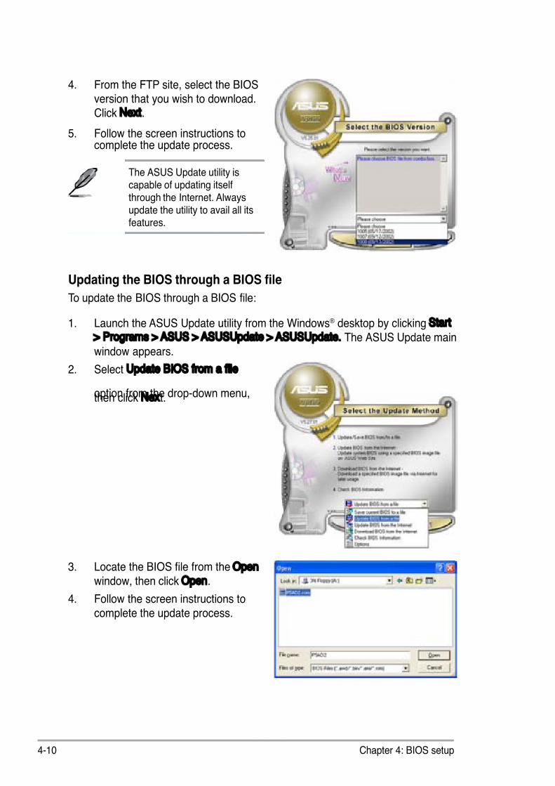
7/27/2019 (E3241)_M2N4-SLI
http://slidepdf.com/reader/full/e3241m2n4-sli 66/138
4-10 Chapter 4: BIOS setup
Updating the BIOS through a BIOS le
To update the BIOS through a BIOS le:
1. Launch the ASUS Update utility from the Windows® desktop by clicking Start
> Programs > ASUS > ASUSUpdate > ASUSUpdate. The ASUS Update mainwindow appears.
2. Select Update BIOS from a le
option from the drop-down menu,then click Next.
4. From the FTP site, select the BIOSversion that you wish to download.
Click Next.
5. Follow the screen instructions tocomplete the update process.
The ASUS Update utility iscapable of updating itselfthrough the Internet. Alwaysupdate the utility to avail all itsfeatures.
3. Locate the BIOS le from the Open
window, then click Open.
4. Follow the screen instructions to
complete the update process.

7/27/2019 (E3241)_M2N4-SLI
http://slidepdf.com/reader/full/e3241m2n4-sli 67/138

7/27/2019 (E3241)_M2N4-SLI
http://slidepdf.com/reader/full/e3241m2n4-sli 68/138
4-12 Chapter 4: BIOS setup
F1:Help ↑↓ : Select Item -/+: Change Value F5: Setup DefaultsESC: Exit →←: Select Menu Enter: Select Sub-menu F10: Save and Exit
Phoenix-Award BIOS CMOS Setup Utility
Main Advanced Power Boot Exit
Select Menu
Item Specic Help
Change the day, month,year and century.
System Time 15 : 30 : 36
System Date Wed, Nov 5 2004
Legacy Diskette A: [1.44M, 3.5 in.]
Primary IDE Master [ST321122A]Primary IDE Slave [ASUS CDS520/A]
Secondary IDE Master [None]
Secondary IDE Slave [None] SATA 1 [None]
SATA 2 [None]
SATA 3 [None]
SATA 4 [None]
4.2.2 Menu bar
The menu bar on top of the screen has the following main items:
Main For changing the basic system conguration
Advanced For changing the advanced system settings
Power For changing the advanced power management (APM)
conguration
Boot For changing the system boot conguration
Exit For selecting the exit options and loading default
settings
To select an item on the menu bar, press the right or left arrow key on the keyboarduntil the desired item is highlighted.
4.2.1 BIOS menu screen
• The BIOS setup screens shown in this chapter are for reference purposesonly, and may not exactly match what you see on your screen.
• Visit the ASUS website (www.asus.com) to download the latest BIOS
information.
Legend bar
General helpMenu bar
Sub-menu items
Conguration eldsMenu items

7/27/2019 (E3241)_M2N4-SLI
http://slidepdf.com/reader/full/e3241m2n4-sli 69/138
ASUS M2N4-SLI 4-13
4.2.4 Menu items
The highlighted item on the menu bar displays the specic items for that menu.
For example, selecting Main shows the Main menu items.
The other items (Advanced, Power, Boot, and Exit) on the menu bar have their
respective menu items.
4.2.5 Sub-menu items
A solid triangle before each item on any menu screen means that the iteam has asub-menu. To display the sub-menu, select the item and press <Enter>.
4.2.6 Conguration elds
These elds show the values for the menu items. If an item is user-congurable,
you can change the value of the eld opposite the item. You cannot select an item
that is not user-congurable.
A congurable eld is enclosed in brackets, and is highlighted when selected. To
change the value of a eld, select it then press <Enter> to display a list of options.Refer to “4.2.7 Pop-up window.”
4.2.3 Legend bar
At the bottom of the Setup screen is a legend bar. The keys in the legend bar allow
you to navigate through the various setup menus. The following table lists the keysfound in the legend bar with their corresponding functions.
Navigation Key Function
<F1> Displays the General Help screen
<F5> Loads setup default values
<Esc> Exits the BIOS setup or returns to the main menufrom a sub-menu
Left or Right arrow Selects the menu item to the left or right
Up or Down arrow Moves the highlight up or down between elds
Page Down or – (minus) Scrolls backward through the values for thehighlighted eld
Page Up or + (plus) Scrolls forward through the values for the highlightedeld
<Enter> Brings up a selection menu for the highlighted eld
<F10> Saves changes and exit
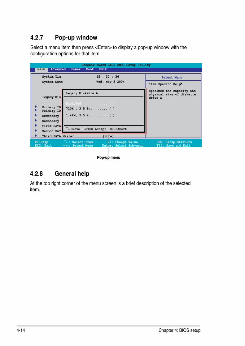
7/27/2019 (E3241)_M2N4-SLI
http://slidepdf.com/reader/full/e3241m2n4-sli 70/138
4-14 Chapter 4: BIOS setup
4.2.7 Pop-up window
Select a menu item then press <Enter> to display a pop-up window with the
conguration options for that item.
F1:Help ↑↓ : Select Item -/+: Change Value F5: Setup DefaultsESC: Exit →←: Select Menu Enter: Select Sub-menu F10: Save and Exit
Phoenix-Award BIOS CMOS Setup Utility
Main Advanced Power Boot Exit
Select Menu
Item Specic Help
Species the capacity and physical size of diskettedrive A.
4.2.8 General help
At the top right corner of the menu screen is a brief description of the selected
item.
Pop-up menu
System Tim 15 : 30 : 36
System Date Wed, Nov 5 2004
Legacy Diskette A: [1.44M, 3.5 in.]
Primary IDE Master [ST321122A]Primary IDE Slave [ASUS CDS520/A]
Secondary IDE Master [None]
Secondary IDE Slave [None]
First SATA Master [None]
Second SATA Slave [None]
Third SATA Master
[None]
Legacy Diskette A:
Disabled ..... [ ]
720K , 3.5 in. ..... [ ]
1.44M, 3.5 in. ..... [ ]
↑↓ :Move ENTER:Accept ESC:Abort

7/27/2019 (E3241)_M2N4-SLI
http://slidepdf.com/reader/full/e3241m2n4-sli 71/138
ASUS M2N4-SLI 4-15
F1:Help ↑↓ : Select Item -/+: Change Value F5: Setup DefaultsESC: Exit →←: Select Menu Enter: Select Sub-menu F10: Save and Exit
Phoenix-Award BIOS CMOS Setup Utility
Main Advanced Power Boot Exit
Select Menu
Item Specic Help
Change the day, month,year and century.
4.3 Main menu
When you enter the BIOS Setup program, the Main menu screen appears, givingyou an overview of the basic system information.
Refer to section “4.2.1 BIOS menu screen” for information on the menu screen
items and how to navigate through them.
4.3.1 System Time [xx:xx:xx]
Allows you to set the system time.
4.3.2 System Date [Day, xx/xx/xxxx]
Allows you to set the system date.
4.3.3 Legacy Diskette A [1.44M, 3.5 in.]
Sets the type of oppy drive installed. Conguration options: [Disabled] [720K , 3.5
in.] [1.44M, 3.5 in.]
System Tim 15 : 30 : 36
System Date Wed, Nov 5 2004
Legacy Diskette A: [1.44M, 3.5 in.]
Primary IDE Master [ST321122A]
Primary IDE Slave [ASUS CDS520/A] Secondary IDE Master [None]
Secondary IDE Slave [None]
SATA 1 [None]
SATA 2 [None]
SATA 3 [None]
SATA 4 [None]

7/27/2019 (E3241)_M2N4-SLI
http://slidepdf.com/reader/full/e3241m2n4-sli 72/138
4-16 Chapter 4: BIOS setup
Before attempting to congure a hard disk drive, make sure you have thecorrect conguration information supplied by the drive manufacturer. Incorrectsettings may cause the system to fail to recognize the installed hard disk.
4.3.5 Primary and Secondary IDE Master/Slave
While entering Setup, the BIOS automatically detects the presence of IDE devices.
There is a separate sub-menu for each IDE device. Select a device item thenpress <Enter> to display the IDE device information.
The BIOS automatically detects the values opposite the dimmed items (Capacity,
Cylinder, Head, Sector and Transfer Mode). These values are not user-congurable. These items show N/A if no IDE device is installed in the system.
Primary IDE Master/Slave [Auto];Secondary IDE Master/Slave [Auto]
Select [Auto] to automatically detect an IDE hard disk drive. If automatic detection
is successful, the BIOS automatically lls in the correct values for the remainingelds on this sub-menu. If the hard disk was already formatted on a previous
system, the setup BIOS may detect incorrect parameters. Select [Manual] to
manually enter the IDE hard disk drive parameters. If no drive is installed select
[None]. Conguration options: [None] [Auto] [Manual]
Access Mode [Auto]
The default [Auto] allows automatic detection of an IDE hard disk drive.Select [CHS] for this item if you set the IDE Primary Master/Slave to [Manual].
Conguration options: [CHS] [LBA] [Large] [Auto]
F1:Help ↑↓ : Select Item -/+: Change Value F5: Setup DefaultsESC: Exit →←: Select Menu Enter: Select Sub-menu F10: Save and Exit
Phoenix-Award BIOS CMOS Setup Utility
Main
Select Menu
Item Specic Help
Press [Enter] toselect
Primary IDE Master
Primary IDE Master [Auto]
Access Mode [Auto]
Capacity xxxxx MB
Cylinder xxxxx
Head xx
Sector xx
PIO Mode [Auto]

7/27/2019 (E3241)_M2N4-SLI
http://slidepdf.com/reader/full/e3241m2n4-sli 73/138

7/27/2019 (E3241)_M2N4-SLI
http://slidepdf.com/reader/full/e3241m2n4-sli 74/138

7/27/2019 (E3241)_M2N4-SLI
http://slidepdf.com/reader/full/e3241m2n4-sli 75/138
ASUS M2N4-SLI 4-19
Head
Shows the number of the hard disk read/write heads. This item is not congurable.
Landing ZoneShows the number of landing zone per track. This item is not congurable.
Sector
Shows the number of sectors per track. This item is not congurable.
After entering the IDE hard disk drive information into BIOS, use a disk utility,such as FDISK, to partition and format new IDE hard disk drives. This is
necessary so that you can write or read data from the hard disk. Make sure toset the partition of the Primary IDE hard disk drives to active.
4.3.7 HDD SMART Monitoring
Allows you to enable or disable the HDD Self-Monitoring Analysis and Reporting
Technology (SMART) feature. Conguration options: [Disabled] [Enabled]
4.3.8 Installed Memory
Shows the size of installed memory.
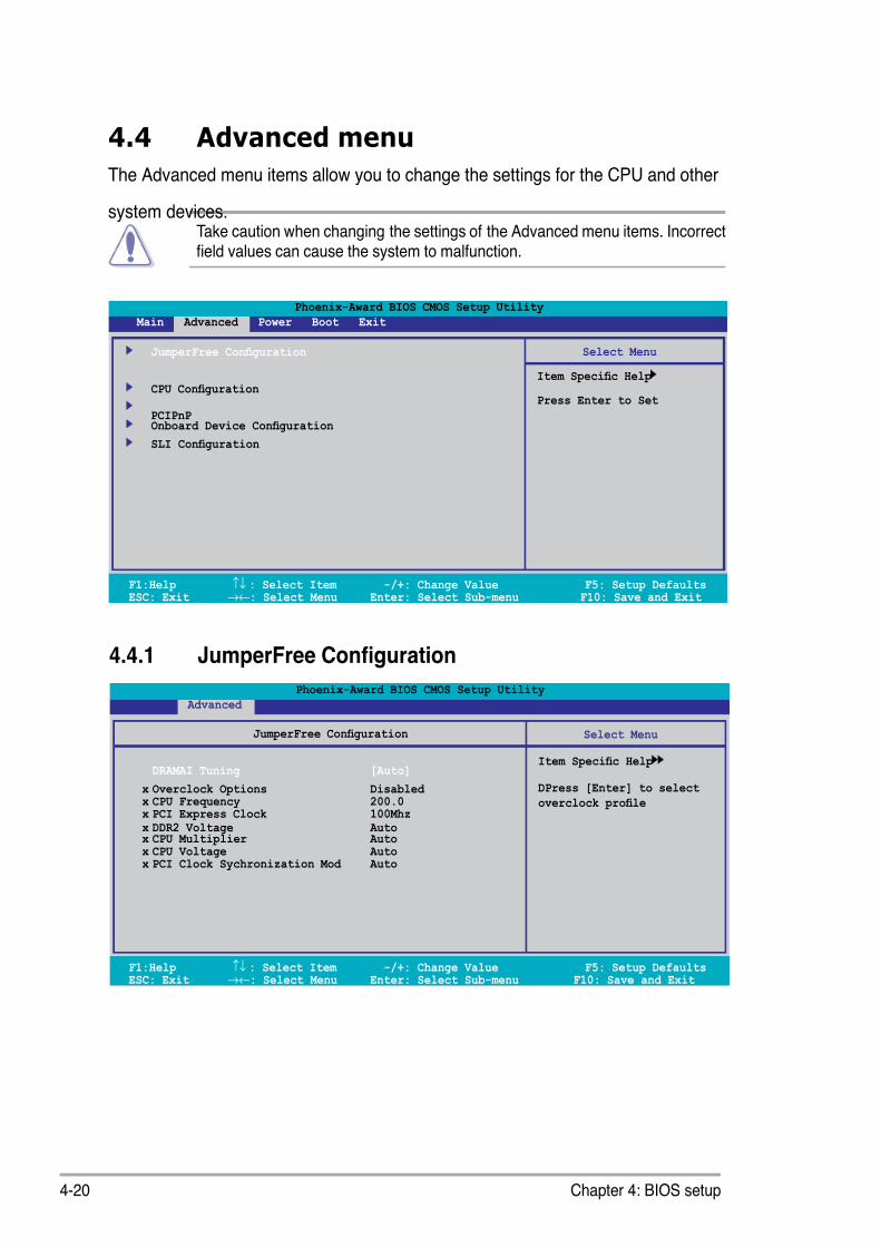
7/27/2019 (E3241)_M2N4-SLI
http://slidepdf.com/reader/full/e3241m2n4-sli 76/138
4-20 Chapter 4: BIOS setup
Phoenix-Award BIOS CMOS Setup Utility
Main Advanced Power Boot Exit
Select Menu
Item Specic Help
Press Enter to Set
JumperFree Conguration
CPU Conguration
PCIPnP Onboard Device Conguration
SLI Conguration
4.4.1 JumperFree Conguration
F1:Help ↑↓ : Select Item -/+: Change Value F5: Setup DefaultsESC: Exit →←: Select Menu Enter: Select Sub-menu F10: Save and Exit
Select Menu
Item Specic Help
DPress [Enter] to select
overclock prole
JumperFree Conguration
DRAMAI Tuning [Auto]
x Overclock Options Disabled x CPU Frequency 200.0 x PCI Express Clock 100Mhz x DDR2 Voltage Auto x CPU Multiplier Auto x CPU Voltage Auto x PCI Clock Sychronization Mod Auto
Phoenix-Award BIOS CMOS Setup Utility
Advanced
4.4 Advanced menu
The Advanced menu items allow you to change the settings for the CPU and other
system devices.Take caution when changing the settings of the Advanced menu items. Incorrecteld values can cause the system to malfunction.
F1:Help ↑↓ : Select Item -/+: Change Value F5: Setup DefaultsESC: Exit →←: Select Menu Enter: Select Sub-menu F10: Save and Exit

7/27/2019 (E3241)_M2N4-SLI
http://slidepdf.com/reader/full/e3241m2n4-sli 77/138
7/27/2019 (E3241)_M2N4-SLI
http://slidepdf.com/reader/full/e3241m2n4-sli 78/138
4-22 Chapter 4: BIOS setup
CPU Voltage [Auto]
Sets the operating CPU voltage. The conguration options vary depending on the
model of processor installed.
PCI Clock Synchronizat ion Mode [Auto]
Sets the PCI Clock Synchronization mode.
Conguration options: [Auto] [To CPU] [33.33MHz]

7/27/2019 (E3241)_M2N4-SLI
http://slidepdf.com/reader/full/e3241m2n4-sli 79/138
ASUS M2N4-SLI 4-23
F1:Help ↑↓ : Select Item -/+: Change Value F5: Setup DefaultsESC: Exit →←: Select Menu Enter: Select Sub-menu F10: Save and Exit
Select Menu
Item Specic Help
DRAM timing and control
Onboard Device Conguration
CPU Type AMD Sempron(tm) Processor 3200+
CPU Speed 1800MHz
Cache RAM 128K Dram Conguration
Hyper Transport Frequency [4x]
Phoenix-Award BIOS CMOS Setup Utility
Advanced
4.4.3 CPU Conguration
DRAM Conguration
The items in this sub-menu show the DRAM-related information auto-detected by
the BIOS.
F1:Help ↑↓ : Select Item -/+: Change Value F5: Setup DefaultsESC: Exit →←: Select Menu Enter: Select Sub-menu F10: Save and Exit
Select Menu
Item Specic Help
Setting platform Memclockor limit valu
DRAM Conguration
Memory Clock Frequency [Auto]
Tcl [Auto]
Trcd [Auto]
Trp [Auto]
Tras [Auto]
Trc [Auto]
Twr [Auto]
Trrd [Auto]
Trwt [Auto] Twtr [Auto] Trtp [Auto]
Phoenix-Award BIOS CMOS Setup Utility
Advanced
Memory Clock Frequency[Auto]
Sets platform Memclock or limit value. Configuration options:[Auto] [DDR2 400] [DDR2 533] [DDR2 667] [DDR2 800]
Tcl[Auto]
Conguration options: [Auto] [3] [4] [5] [6]

7/27/2019 (E3241)_M2N4-SLI
http://slidepdf.com/reader/full/e3241m2n4-sli 80/138
4-24 Chapter 4: BIOS setup
Trcd[Auto]
Conguration options: [Auto] [3] [4] [5] [6]
Trp[Auto]
Conguration options: [Auto] [3] [4] [5] [6]
Tras[Auto]
Conguration options: [Auto] [5] [6] [7] [8] [9] [10] [11] [12] [13] [14] [15] [16] [17]
[18]
Trc[Auto]
Conguration options: [Auto] [11] [12] [13] [14] [15] [16] [17] [18] [19] [20] [21] [22]
[23] [24] [25] [26]
Twr[Auto]
Conguration options: [Auto] [3] [4] [5] [6]
Trrd[Auto]
Conguration options: [Auto] [2] [3] [4] [5]
Trwt[Auto]
Conguration options: [Auto] [2] [3] [4] [5] [6] [7] [8] [9]
Twtr[Auto]
Conguration options: [Auto] [1] [2] [3]
Trtp[Auto]
Conguration options: [Auto] [2/4] [3/5]
Twrrd[Auto]
Conguration options: [Auto] [0] [1] [2] [3]
Twrwr[Auto]
Conguration options: [Auto] [1] [2] [3]
Trdrd[Auto]
Conguration options: [Auto] [2] [3] [4] [5]
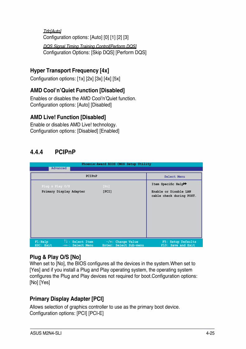
7/27/2019 (E3241)_M2N4-SLI
http://slidepdf.com/reader/full/e3241m2n4-sli 81/138
ASUS M2N4-SLI 4-25
Trfc[Auto]
Conguration options: [Auto] [0] [1] [2] [3]
DQS Signal Timing Training Control[Perform DQS]
Conguration Options: [Skip DQS] [Perform DQS]
Hyper Transport Frequency [4x]
Conguration options: [1x] [2x] [3x] [4x] [5x]
AMD Cool’n’Quiet Function [Disabled]
Enables or disables the AMD Cool’n’Quiet function.
Conguration options: [Auto] [Disabled]
AMD Live! Function [Disabled]
Enable or disables AMD Live! technology.Conguration options: [Disabled] [Enabled]
F1:Help ↑↓ : Select Item -/+: Change Value F5: Setup DefaultsESC: Exit →←: Select Menu Enter: Select Sub-menu F10: Save and Exit
PCIPnP
Plug & Play O/S [ No]
Primary Display Adapter [PCI]
Phoenix-Award BIOS CMOS Setup Utility
Advanced
4.4.4 PCIPnP
Plug & Play O/S [No] When set to [No], the BIOS congures all the devices in the system.When set to
[Yes] and if you install a Plug and Play operating system, the operating systemcongures the Plug and Play devices not required for boot.Conguration options:
[No] [Yes]
Primary Display Adapter [PCI]
Allows selection of graphics controller to use as the primary boot device.
Conguration options: [PCI] [PCI-E]
Select Menu
Item Specic Help
Enable or Disable LAN
cable check during POST.

7/27/2019 (E3241)_M2N4-SLI
http://slidepdf.com/reader/full/e3241m2n4-sli 82/138

7/27/2019 (E3241)_M2N4-SLI
http://slidepdf.com/reader/full/e3241m2n4-sli 83/138
ASUS M2N4-SLI 4-27
SATA Port 1, 2[Enabled]
Allows to disable or enable OnChip SATA(Port 1, Port 2) Conguration options: [Disabled] [Enabled]
SATA DMA transfer [Enabled]
Allows to disable or enable to switch to support SATA DMA tranfer
Conguration options: [Disabled] [Enabled]
SATA Port 3, 4[Enabled]
Allows to disable or enable OnChip SATA2(Port 3, Port 4)
Conguration options: [Disabled] [Enabled]
SATA2 DMA transfer [Enabled]
Allows to disable or enable to switch to support SATA2 DMA tranfer Conguration options: [Disabled] [Enabled]
IDE Prefetch Mode[Enabled]
Allows to disable or enable IDE PIO read prefetch mode. When prefetch isenabled, either 16-bit or 32-bit are allowed on IDE bus.
Conguration options: [Disabled] [Enabled]

7/27/2019 (E3241)_M2N4-SLI
http://slidepdf.com/reader/full/e3241m2n4-sli 84/138
4-28 Chapter 4: BIOS setup
NVRAID Conguration
This item in this sub-menu allows you to set up RAID feature.
F1:Help ↑↓ : Select Item -/+: Change Value F5: Setup DefaultsESC: Exit →←: Select Menu Enter: Select Sub-menu F10: Save and Exit
Select Menu
Item Specic Help
NVRAID Conguration
RAID Enable [Disabled]
x IDE Primary Master RAID [Disabled]
x IDE Primary Slave RAID [Disabled]
x IDE Secondary Master RAID [Disabled] x IDE Secondary Slave RAID [Disabled] x First SATA Master RAID [Disabled] x Second SATA Master RAID [Disabled] x Third SATA Master RAID [Disabled] x Fourth SATA Master RAID [Disabled]
Phoenix-Award BIOS CMOS Setup Utility
Advanced
RAID Enable[Disabled]
Allows to disable or enable nVIDIA RAID feature.
Conguration options: [Disabled] [Enabled]
IDE Primary Master RAID[Disabled]
Selects this device as RAID set.
Conguration options: [Disabled] [Enabled]
IDE Primary Slave RAID[Disabled]
Selects this device as RAID set.
Conguration options: [Disabled] [Enabled]
IDE Secondary Master RAID[Disabled]
Selects this device as RAID set.
Conguration options: [Disabled] [Enabled]
IDE Secondary Slave RAID[Disabled]
Selects this device as RAID set.
Conguration options: [Disabled] [Enabled]
First SATA Maser RAID[Disabled]
Selects this device as RAID set.
Conguration options: [Disabled] [Enabled]
The following items are user-congurable only when the RAID Enable is set to
[Enabled].

7/27/2019 (E3241)_M2N4-SLI
http://slidepdf.com/reader/full/e3241m2n4-sli 85/138
ASUS M2N4-SLI 4-29
USB Controller[enabled]
Enables or disables USB 1.1 and 2.0 Controller
Conguration options: [Disabled] [Enabled]
USB Conguration
The items in this sub-menu allows you to set the USB conguration.
F1:Help ↑↓ : Select Item -/+: Change Value F5: Setup DefaultsESC: Exit →←: Select Menu Enter: Select Sub-menu F10: Save and Exit
Select Menu
Item Specic Help
Press [Enter] to set.
USB Conguration
USB Controller [Enabled] USB 2.0 Controller [Enabled] USB Legacy support [Enabled]
Phoenix-Award BIOS CMOS Setup Utility
Advanced
Second SATA Maser RAID[Disabled] Selects this device as RAID set.Configuration options: [Disabled] [Enabled]
Third SATA Maser RAID[Disabled]
Selects this device as RAID set.Conguration options: [Disabled] [Enabled]
Fourth SATA Maser RAID[Disabled]
Selects this device as RAID set.
Conguration options: [Disabled] [Enabled]
When USB Controller is set to [Disabled], both USB 2.0 Controller and USBLegacy support will be disabled..
USB 2.0 Controller[enabled] Enables or disables 2.0 Controller
Conguration options: [Disabled] [Enabled]

7/27/2019 (E3241)_M2N4-SLI
http://slidepdf.com/reader/full/e3241m2n4-sli 86/138
4-30 Chapter 4: BIOS setup
USB 2.0 Legacy support[enabled] Enables or disables USB legacy device (USB keyboard and USB mouse)
support. Conguration options: [Disabled] [Enabled]
Onboard nVidia LAN[Enabled]
Enable or Disable Onboard NV LAN Interface.
Conguration options: [Enabled] [Disabled]
Onboard LAN Boot ROM[Disabled]
Enable or Disable the bootrom of the onboard LAN.
Conguration options: [Enabled] [Disabled]
AC97 Audio[Enabled]
Enable or Disable Onboard AC 97.
Conguration options: [Enabled] [Disabled]
Serial Port1 Address [3F8/IRQ4]
Allows you to select the Serial Port1 base address.
Conguration options: [Disabled] [3F8/IRQ4] [2F8/IRQ3] [3E8/IRQ4][2E8/IRQ3] [Auto]
Parallel Port Address [378/IRQ7]Allows you to select the Parallel Port base addresses.
Conguration options: [Disabled] [378/IRQ7] [278/IRQ5] [3BC/IRQ7]
Parallel Port Mode [ECP+EPP]
Allows you to select the Parallel Port mode.
Conguration options: [SPP] [EPP] [ECP] [ECP+EPP]
ECP Mode Use DMA [3]
Allows selection of ECP Mode. Conguration options: [1] [3]

7/27/2019 (E3241)_M2N4-SLI
http://slidepdf.com/reader/full/e3241m2n4-sli 87/138

7/27/2019 (E3241)_M2N4-SLI
http://slidepdf.com/reader/full/e3241m2n4-sli 88/138

7/27/2019 (E3241)_M2N4-SLI
http://slidepdf.com/reader/full/e3241m2n4-sli 89/138
ASUS M2N4-SLI 4-33
4.5.3 APM Conguration
F1:Help ↑↓ : Select Item -/+: Change Value F5: Setup DefaultsESC: Exit →←: Select Menu Enter: Select Sub-menu F10: Save and Exit
Select Menu
Item Specic Help
Press [ENTER] to
select whether or not
to restart the system
after AC power loss.
APM Conguration
Restore on AC Power Loss [Power-Off]
PWR Button < 4 secs [Instant-Off]
Power On By PCI/PCIE Devices [Disabled]
Power On By External Modems [Disabled]
Power-On by RTC Alarm [Disabled]
x Date (of Month) 0
x Resume Time (hh:mm) 0 : 0 : 0
Phoenix-Award BIOS CMOS Setup Utility
Power
Restore on AC Power Loss [Power-Off]
Allows you to enable or disable the Restore on AC Power Loss function.Conguration options: [Power-Off] [Power-On]
PWR Button < 4 secs [Instant-Off]
Allows you to set the event after the power button is pressed for more than 4
seconds. Conguration options: [Suspend] [Instant-Off]
Power On By PCI Devices [Disabled]
When set to [Enabled], this parameter allows you to turn on the system through a
PCI LAN or modem card. This feature requires an ATX power supply that provides
at least 1A on the +5VSB lead.Conguration options: [Disabled] [Enabled]
Power On By External Modems [Disabled]
This allows either settings of [Enabled] or [Disabled] for powering up the computerwhen the external modem receives a call while the computer is in Soft-off mode.
Conguration options: [Disabled] [Enabled]
The computer cannot receive or transmit data until the computer andapplications are fully running. Thus, connection cannot be made on the rsttry. Turning an external modem off and then back on while the computer is offcauses an initialization string that turns the system power on.

7/27/2019 (E3241)_M2N4-SLI
http://slidepdf.com/reader/full/e3241m2n4-sli 90/138
4-34 Chapter 4: BIOS setup
Power On By RTC Alarm [Disabled]
Allows you to enable or disable RTC to generate a wake event. When this
item is set to Enabled, the items Date of Month Alarm and Time (hh:mm:ss)Alarm items become user-congurable with set values.
Conguration options: [Disabled] [Enabled]
Day of Month Alarm [Disabled]
To set the date of alarm, highlight this item and press <Enter> to display the Day
of Month Alarm pop-up menu. Key-in a value within the specied range then press
<Enter>. Conguration options: [Min=0] [Max=31]
Time (hh:mm) Alarm [Disabled]
To set the time of alarm:
1. Highlight this item and press <Enter> to display a pop-up menu for the hour
eld.
2. Key-in a value (Min=0, Max=23), then press <Enter>.
3. Press <TAB> to move to the minutes eld then press <Enter>.
4. Key-in a minute value (Min=0, Max=59), then press <Enter>.
5. Press <TAB> to move to the seconds eld then press <Enter>.
6. Key-in a value (Min=0, Max=59), then press <Enter>.
Power Up By PS/2 Mouse [Disabled]
When set to [Enabled], this parameter allows you to use the PS/2 mouse to turn onthe system. This feature requires an ATX power supply that provides at least 1A on
the +5VSB lead. Conguration options: [Disabled] [Enabled]
Power On By PS/2 Keyboard [Disabled]
Allows you to disable the Power On by PS/2 keyboard function or set specic
keys on the PS/2 keyboard to turn on the system. This feature requires an ATXpower supply that provides at least 1A on the +5VSB lead. Conguration options:[Disabled] [Space Bar] [Ctrl-ESC] [Power Key]

7/27/2019 (E3241)_M2N4-SLI
http://slidepdf.com/reader/full/e3241m2n4-sli 91/138

7/27/2019 (E3241)_M2N4-SLI
http://slidepdf.com/reader/full/e3241m2n4-sli 92/138

7/27/2019 (E3241)_M2N4-SLI
http://slidepdf.com/reader/full/e3241m2n4-sli 93/138

7/27/2019 (E3241)_M2N4-SLI
http://slidepdf.com/reader/full/e3241m2n4-sli 94/138

7/27/2019 (E3241)_M2N4-SLI
http://slidepdf.com/reader/full/e3241m2n4-sli 95/138

7/27/2019 (E3241)_M2N4-SLI
http://slidepdf.com/reader/full/e3241m2n4-sli 96/138

7/27/2019 (E3241)_M2N4-SLI
http://slidepdf.com/reader/full/e3241m2n4-sli 97/138
ASUS M2N4-SLI 4-41
4.6.6 Security
F1:Help ↑↓ : Select Item -/+: Change Value F5: Setup DefaultsESC: Exit →←: Select Menu Enter: Select Sub-menu F10: Save and Exit
Select Menu
Item Specic Help
Supervisor password
controls full access,
<Enter> to change
password.
Boot Settings Conguration
Supervisor Password Clear
User Password Clear
Password Check [Setup]
Phoenix-Award BIOS CMOS Setup Utility
Boot
Supervisor PasswordUser Password
These elds allow you to set passwords:
To set a password:
1. Select an item then press <Enter>.
2. Type in a password using a combination of a maximum of eight (8) alpha-
numeric characters, then press <Enter>.
3. When prompted, conrm the password by typing the exact characters again,
then press <Enter>. The password eld setting is changed to Set.
To clear the password:
1. Select the password eld and press <Enter> twice. The following message
appears:
PASSWORD DISABLED !!!
Press any key to continue...
2. Press any key to continue. The password eld setting is changed to Clear.

7/27/2019 (E3241)_M2N4-SLI
http://slidepdf.com/reader/full/e3241m2n4-sli 98/138

7/27/2019 (E3241)_M2N4-SLI
http://slidepdf.com/reader/full/e3241m2n4-sli 99/138

7/27/2019 (E3241)_M2N4-SLI
http://slidepdf.com/reader/full/e3241m2n4-sli 100/138
4-44 Chapter 4: BIOS setup
Phoenix-Award BIOS CMOS Setup Utility
Main Advanced Power Boot Tools Exit
Select Menu
Item Specic Help
This option save datato CMOS and exitingthe setup menu.
Exit & Save Changes
Exit & Discard Changes
Load Setup Default
F1:Help ↑↓ : Select Item -/+: Change Value F5: Setup DefaultsESC: Exit →←: Select Menu Enter: Select Sub-menu F10: Save and Exit
4.8 Exit menu
The Exit menu items allow you to load the optimal or failsafe default values for the
BIOS items, and save or discard your changes to the BIOS items.
Exit & Save ChangesOnce you are nished making your selections, choose this option from the Exit
menu to ensure the values you selected are saved to the CMOS RAM. An onboardbackup battery sustains the CMOS RAM so it stays on even when the PC is turned
off. When you select this option, a conrmation window appears. Select Yes to
save changes and exit.
Pressing <Esc> does not immediately exit this menu. Select one of the optionsfrom this menu or <F10> from the legend bar to exit.
Exit & Discard Changes
Select this option only if you do not want to save the changes that you made to
the Setup program. If you made changes to elds other than System Date, System
Time, and Password, the BIOS asks for a conrmation before exiting.
If you attempt to exit the Setup program without saving your changes, the
program prompts you with a message asking if you want to save your changes
before exiting. Press <Enter> to save the changes while exiting.

7/27/2019 (E3241)_M2N4-SLI
http://slidepdf.com/reader/full/e3241m2n4-sli 101/138

7/27/2019 (E3241)_M2N4-SLI
http://slidepdf.com/reader/full/e3241m2n4-sli 102/138
4-46 Chapter 4: BIOS setup
7/27/2019 (E3241)_M2N4-SLI
http://slidepdf.com/reader/full/e3241m2n4-sli 103/138
5 Softwaresupport
This chapter describes the contentsof the support CD that comes with the
motherboard package.

7/27/2019 (E3241)_M2N4-SLI
http://slidepdf.com/reader/full/e3241m2n4-sli 104/138

7/27/2019 (E3241)_M2N4-SLI
http://slidepdf.com/reader/full/e3241m2n4-sli 105/138
ASUS M2N4-SLI 5-1
If Autorun is NOT enabled in your computer, browse the contents of the supportCD to locate the le ASSETUP.EXE from the BIN folder. Double-click theASSETUP.EXE to run the CD.
Click an item to install
5.1 Installing an operating system
This motherboard supports Windows® 2000/XP operating systems (OS). Alwaysinstall the latest OS version and corresponding updates to maximize the features
of your hardware.
5.2 Support CD information
The support CD that came with the motherboard package contains the drivers,
software applications, and utilities that you can install to avail all motherboardfeatures.
5.2.1 Running the support CD
Place the support CD to the optical drive. The CD automatically displays theDrivers menu if Autorun is enabled in your computer.
• Motherboard settings and hardware options vary. Use the setupprocedures presented in this chapter for reference only. Refer to your OSdocumentation for detailed information.
• Make sure that you install Windows® 2000 Service Pack 4 or the Windows® XP Service Pack2 or later versions before installing the drivers for bettercompatibility and system stability.
The contents of the support CD are subject to change at any time withoutnotice. Visit the ASUS website(www.asus.com) for updates.
Click an icon to displaysupport CD/motherboardinformation

7/27/2019 (E3241)_M2N4-SLI
http://slidepdf.com/reader/full/e3241m2n4-sli 106/138
5-2 Chapter 5: Software support
5.2.2 Drivers menu
The drivers menu shows the available device drivers if the system detects installed
devices. Install the necessary drivers to activate the devices.
NVIDIA nForce Chipset Driver
Installs the NVIDIA® Chipset drivers for the NVIDIA® nForce™ 500 SLI chipset.
Realtek Audio Driver
Installs the Realtek® audio driver and application.
AMD Cool’n’Quiet Driver
Installs the AMD Cool ‘n’ Quiet! driver and application.
USB 2.0 DriverInstalls the Universal Serial Bus 2.0 (USB 2.0) driver.

7/27/2019 (E3241)_M2N4-SLI
http://slidepdf.com/reader/full/e3241m2n4-sli 107/138

7/27/2019 (E3241)_M2N4-SLI
http://slidepdf.com/reader/full/e3241m2n4-sli 108/138

7/27/2019 (E3241)_M2N4-SLI
http://slidepdf.com/reader/full/e3241m2n4-sli 109/138
ASUS M2N4-SLI 5-5
5.2.5 ASUS Contact information
Click the Contact tab to display the ASUS contact information. You can also nd
this information on the inside front cover of this user guide.
5.2.6 Other information
The icons on the top right corner of the screen give additional information on the
motherboard and the contents of the support CD. Click an icon to display thespecied information.
Motherboard Info
Displays the general specications of the motherboard.

7/27/2019 (E3241)_M2N4-SLI
http://slidepdf.com/reader/full/e3241m2n4-sli 110/138

7/27/2019 (E3241)_M2N4-SLI
http://slidepdf.com/reader/full/e3241m2n4-sli 111/138

7/27/2019 (E3241)_M2N4-SLI
http://slidepdf.com/reader/full/e3241m2n4-sli 112/138

7/27/2019 (E3241)_M2N4-SLI
http://slidepdf.com/reader/full/e3241m2n4-sli 113/138
ASUS M2N4-SLI 5-9
• THE AMD Cool ‘n’ Quiet™ technology feature works only with the AMDheatsink and fan assembly with monitor chip.
• If you purchased a separate heatsink and fan package, use theASUS Q-Fan technology feature to automatically adjust the CPU fan speedaccording to your system loading.
Launching the Cool ‘n’ Quiet!™ software
The motherboard support CD includes the Cool ‘n’ Quiet!™ software that enables
you to view your system’s real-time CPU Frequency and voltage.
To launch the Cool ‘n’ Quiet!™ program:
1. If you are using Windows® 2000, click the Start button. Select Programs->
ASUS -> Cool & Quiet -> Cool & Quiet.
2. If you are using Windows® XP, click the Start button. Select All Programs->
ASUS -> Cool & Quiet -> Cool & Quiet.
3. The Cool ‘n’ Quiet!™ technology screen appears and displays the currentCPU Frequency and CPU Voltage.
Make sure to install the Cool ‘n’ Quiet!™ software from the motherboard support
CD. Refer to section “5.2.3 Utilities menu” for details.

7/27/2019 (E3241)_M2N4-SLI
http://slidepdf.com/reader/full/e3241m2n4-sli 114/138

7/27/2019 (E3241)_M2N4-SLI
http://slidepdf.com/reader/full/e3241m2n4-sli 115/138
ASUS M2N4-SLI 5-11
Opens the Conguration window
Opens the Report window Opens the Desktop Management Interface window
Opens the Peripheral Component Interconnect window
Opens the Windows Management Instrumentation window
Opens the hard disk drive, memory, CPU usage window
Shows/Hides the Preference section
Minimizes the application
Closes the application
Sensor alert
When a system sensor detects a problem, the main window right handle turns red,as the illustrations below show.
When displayed, the monitor panel for that sensor also turns red. Refer to theMonitor panels section for details.
PreferencesYou can customize the application using thePreference section in the main window. Click
the box before each preference to activate or
deactivate.
Button Function

7/27/2019 (E3241)_M2N4-SLI
http://slidepdf.com/reader/full/e3241m2n4-sli 116/138
5-12 Chapter 5: Software support
Changing the monitor panels position
To change the position of the monitor panels in the desktop, click
the arrow down button of the Scheme options, then select another
position from the list box. Click OK when nished.
Moving the monitor panels
All monitor panels move together using a magnetic effect. If you want
to detach a monitor panel from the group, click
the horseshoe magnet icon. You can now move
or reposition the panel independently.
Hardware monitor panels
The hardware monitor panels display the current value of a system sensor such as
fan rotation, CPU temperature, and voltages.
The hardware monitor panels come in two display modes: hexagonal (large) andrectangular (small). When you check the Enable Monitoring Panel option from the
Preference section, the monitor panels appear on your computer’s desktop.
Large display
Small display
Click toincreasevalue
Click todecrease
value
Adjusting the sensor threshold value
You can adjust the sensor threshold valuein the monitor panel by clicking the or
buttons. You can also adjust the threshold
values using the Cong window.
You cannot adjust the sensor thresholdvalues in a small monitoring panel.

7/27/2019 (E3241)_M2N4-SLI
http://slidepdf.com/reader/full/e3241m2n4-sli 117/138
ASUS M2N4-SLI 5-13
Monitoring sensor alert
The monitor panel turns red when a component value exceeds or is lower than the
threshold value. Refer to the illustrations below.
Large display
Small display
WMI browser
Click to display the
WMI (Windows ManagementInstrumentation) browser. This
browser displays various Windows®
management information. Click an
item from the left panel to display onthe right panel. Click the plus sign (+)
before WMI Information to display theavailable information.
DMI browser
Click to display the DMI(Desktop Management Interface)
browser. This browser displays various
desktop and system information.Click the plus sign (+) before DMI
Information to display the available
information.
You can enlarge or reduce the browser size by dragging the bottom right cornerof the browser.

7/27/2019 (E3241)_M2N4-SLI
http://slidepdf.com/reader/full/e3241m2n4-sli 118/138
5-14 Chapter 5: Software support
PCI browser
Click to display the PCI
(Peripheral Component Interconnect)
browser. This browser providesinformation on the PCI devices installed
on your system. Click the plus sign
(+) before the PCI Information item to
display available information.
UsageThe Usage browser displays real-time information on the CPU, hard disk drive
space, and memory usage. Click to display the Usage browser.
CPU usage
The CPU tab displays real-time CPU
usage in line graph representation.
Hard disk drive space usage
The Hard Disk tab displays the usedand available hard disk drive space.
The left panel of the tab lists all logical
drives. Click a hard disk drive to display
the information on the right panel. Thepie chart at the bottom of the window
represents the used (blue) and the
available HDD space.

7/27/2019 (E3241)_M2N4-SLI
http://slidepdf.com/reader/full/e3241m2n4-sli 119/138
ASUS M2N4-SLI 5-15
Memory usage
The Memory tab shows both used
and available physical memory. Thepie chart at the bottom of the windowrepresents the used (blue) and the
available physical memory.
Conguring PC Probe IIClick to view and adjust the sensor threshold values.
The Cong window has two tabs: Sensor/Threshold and Preference. The Sensor/
Threshold tab enables you to activate the sensors or to adjust the sensor threshold
values. The Preference tab allows you to customize sensor alerts, or change the
temperature scale.
Loads the defaultthreshold values for
each sensor
Applies yourchanges
Cancels orignores your
changes
Loads your savedconguration
Saves yourconguration

7/27/2019 (E3241)_M2N4-SLI
http://slidepdf.com/reader/full/e3241m2n4-sli 120/138
5-16 Chapter 5: Software support
5.4 RAID congurations
The motherboard comes with the NVIDIA® SLI Southbridge RAID controllers thatallow you to congure IDE and Serial ATA hard disk drives as RAID sets. The
motherboard supports the following RAID congurations.
RAID 0 (Data striping) optimizes two identical hard disk drives to read and writedata in parallel, interleaved stacks. Two hard disks perform the same work as a
single drive but at a sustained data transfer rate, double that of a single disk alone,thus improving data access and storage. Use of two new identical hard disk drives
is required for this setup.
RAID 1 (Data mirroring ) copies and maintains an identical image of data from one
drive to a second drive. If one drive fails, the disk array management softwaredirects all applications to the surviving drive as it contains a complete copy of
the data in the other drive. This RAID conguration provides data protection and
increases fault tolerance to the entire system. Use two new drives or use an
existing drive and a new drive for this setup. The new drive must be of the samesize or larger than the existing drive.
RAID 0+1 is data striping and data mirroring combined without parity (redundancy
data) having to be calculated and written. With the RAID 0+1 conguration you get
all the benets of both RAID 0 and RAID 1 congurations. Use four new hard disk
drives or use an existing drive and three new drives for this setup.
RAID 5 stripes both data and parity information across three or more hard
disk drives. Among the advantages of RAID 5 conguration include better
HDD performance, fault tolerance, and higher storage capacity. The RAID
5 conguration is best suited for transaction processing, relational databaseapplications, enterprise resource planning, and other business systems. Use a
minimum of three identical hard disk drives for this setup.
RAID 1+0 is a striped conguration with each stripe a RAID 1 array of drives. It
combines the features of both RAID 1 and RAID 0. Fault tolerance is provided
through mirroring while adding performance through striping . This offers higher
performance than a RAID 1 conguration but at a much higher cost. A minimum offour hard disk drives is required for this setup.
JBOD (Spanning) stands for Just a Bunch of Disks and refers to hard disk drives
that are not yet congured as a RAID set. This conguration stores the samedata redundantly on multiple disks that appear as a single disk on the operating
system. Spanning does not deliver any advantage over using separate disks
independently and does not provide fault tolerance or other RAID performance
benets.

7/27/2019 (E3241)_M2N4-SLI
http://slidepdf.com/reader/full/e3241m2n4-sli 121/138
ASUS M2N4-SLI 5-17
5.4.1 Installing hard disks
The motherboard supports Ultra DMA /133/100/66 and Serial ATA hard disk drives.For optimal performance, install identical drives of the same model and capacity
when creating a disk array.
Installing Parallel ATA hard disks
To install IDE hard disks for a RAID conguration:
1. Set the jumpers of each hard disk as Master/Master or Slave/Slave.
2. Install the hard disks into the drive bays.
3. Connect the HDD signal cables.
4. Connect a 4-pin power cable to the power connector on each drive.
Installing Serial ATA (SATA) hard disks
To install the SATA hard disks for a RAID conguration:
1. Install the SATA hard disks into the drive bays.
2. Connect the SATA signal cables.
3. Connect a SATA power cable to the power connector on each drive.
If you want to boot the system from a hard disk drive included in a RAID set,copy rst the RAID driver from the support CD to a oppy disk before you installan operating system to a selected hard disk drive. Refer to section “5.6 Creatinga RAID driver disk” for details.
Refer to the RAID controllers user manual in the motherboard support CD fordetailed information on RAID congurations. See section “5.2.4 Manuals menu”.

7/27/2019 (E3241)_M2N4-SLI
http://slidepdf.com/reader/full/e3241m2n4-sli 122/138

7/27/2019 (E3241)_M2N4-SLI
http://slidepdf.com/reader/full/e3241m2n4-sli 123/138

7/27/2019 (E3241)_M2N4-SLI
http://slidepdf.com/reader/full/e3241m2n4-sli 124/138

7/27/2019 (E3241)_M2N4-SLI
http://slidepdf.com/reader/full/e3241m2n4-sli 125/138
ASUS M2N4-SLI 5-21
Rebuilding a RAID array
To rebuild a RAID array:
1. From the Array List menu, use the up or down arrow keys to select a RAID
array then press <Enter>. The RAID Array details appear.
[Ctrl-X]Exit [↑↓]Select [B]Set Boot [N]New Array [ENTER]Detail
NVIDIA RAID Utility Oct 5 2004
- Array List -
Boot Id Status Vendor Array Model Name
No 4 Healthy NVIDIA MIRROR XXX.XXG
A new set of navigation keys is displayed on the bottom of the screen.
6. Press <Ctrl+X> to save settings and exit.
[R] Rebuild [D] Delete [C] Clear Disk [ENTER] Return
Array 1 : NVIDIA MIRROR XXX.XXG
- Array Detail -
RAID Mode: Mirroring
Striping Width: 1 Striping Block: 64K
Adapt Channel M/S Index Disk Model Name Capacity
2 1 Master 0 XXXXXXXXXXXXXXXXX XXX.XXGB 1 0 Master 1 XXXXXXXXXXXXXXXXX XXX.XXGB

7/27/2019 (E3241)_M2N4-SLI
http://slidepdf.com/reader/full/e3241m2n4-sli 126/138

7/27/2019 (E3241)_M2N4-SLI
http://slidepdf.com/reader/full/e3241m2n4-sli 127/138

7/27/2019 (E3241)_M2N4-SLI
http://slidepdf.com/reader/full/e3241m2n4-sli 128/138

7/27/2019 (E3241)_M2N4-SLI
http://slidepdf.com/reader/full/e3241m2n4-sli 129/138

7/27/2019 (E3241)_M2N4-SLI
http://slidepdf.com/reader/full/e3241m2n4-sli 130/138

7/27/2019 (E3241)_M2N4-SLI
http://slidepdf.com/reader/full/e3241m2n4-sli 131/138
6This chapter tells how to install SLI-readyPCI Express graphics cards.
NVIDIA® SLI™technology
support
7/27/2019 (E3241)_M2N4-SLI
http://slidepdf.com/reader/full/e3241m2n4-sli 132/138
ASUS M2N4-SLI
Chapter summary 66.1 Overview ....................................................................................... 6-1
6.2 Dual graphics cards setup .......................................................... 6-2

7/27/2019 (E3241)_M2N4-SLI
http://slidepdf.com/reader/full/e3241m2n4-sli 133/138
ASUS M2N4-SLI 6-1
6.1 Overview
The motherboard supports the NVIDIA® SLI™ (Scalable Link Interface) technologythat allows you to install two identical PCI Express™ x16 graphics cards. Follow
the installation procedures in this section.
Requirements
• You should have two identical SLI-ready graphics cards that are NVIDIA®
certied.
• Visit the ASUS website (www.asus.com) for a list of qualied SLI-ready
graphics cards for this motherboard.
• Make sure that your graphics card driver supports the NVIDIA SLI technology.
Download the latest driver from the NVIDIA website (www.nvidia.com).
• Make sure that your power supply unit (PSU) can provide at least theminimum power required by your system. See “6. ATX power connectors” on
page 2-27 for details.
• The NVIDIA SLI technology supports Windows® XP™ operating systemonly.
• Visit the NVIDIA website for the supported 3D applications.
• Visit the NVIDIA zone website (http://www.nzone.com) for the latest certied graphics card list.

7/27/2019 (E3241)_M2N4-SLI
http://slidepdf.com/reader/full/e3241m2n4-sli 134/138

7/27/2019 (E3241)_M2N4-SLI
http://slidepdf.com/reader/full/e3241m2n4-sli 135/138
ASUS M2N4-SLI 6-3
4. Insert the second graphics card into the black slot labeled PCIEX16_2. Makesure that the card is properly seated on the slot.
If required, connect an auxiliary power source to the PCI Express graphicscards.
3. Insert one graphics card into the blue slot labeled PCIEX16_1. Make sure
that the card is properly seated on the slot.

7/27/2019 (E3241)_M2N4-SLI
http://slidepdf.com/reader/full/e3241m2n4-sli 136/138

7/27/2019 (E3241)_M2N4-SLI
http://slidepdf.com/reader/full/e3241m2n4-sli 137/138
ASUS M2N4-SLI 6-5
Make sure that your PCI Express graphics card driver supports the NVIDIA SLItechnology. Download the latest driver from the NVIDIA website (www.nvidia.com).
6.2.2 Installing the device drivers
Refer to the documentation that came with your graphics card package to installthe device drivers.
NVIDIA Settings icon
To enable the multi-GPU feature:
1. Click the NVIDIA Settings icon on
your Windows taskbar.
2. From the pop-up menu, selectnView Desktop Manager then click
nView Properties.
6.2.3 Enabling the multi-GPU feature in Windows
After installing your graphics cards and the device drivers, enable the
Multi-Graphics Processing Unit (GPU) feature in the NVIDIA nView properties.
3. From the nView Desktop Manager
window, select the Desktop
Management tab.
4. Click Properties to display the
Display Properties dialog box.

7/27/2019 (E3241)_M2N4-SLI
http://slidepdf.com/reader/full/e3241m2n4-sli 138/138