E200 Series - HILLARY MACHINERY · Quill Dia. : Ø65 (Ø2.5″) ... (1.417 ipm) 960 r/min 0.5...
34
E200 Series HYUNDAI WIA CNC Turning Center
Transcript of E200 Series - HILLARY MACHINERY · Quill Dia. : Ø65 (Ø2.5″) ... (1.417 ipm) 960 r/min 0.5...

E200 SeriesHYUNDAI WIA CNC Turning Center

The CNC Turning Center E200 Series , designed by Hyundai WIA with years of expertise and the latest technology, is designed to maximize productivity by enhancing both technical performance and economic efficiency.
Technical Leader
MODELChuck Size Guideway Turret
6″ 8″ LM Box Standard Turn Mill
E200A ● ● ●
E200C ● ● ●
E200 MA ● ● ●
E200MC ● ● ●
E200PA ● ● ●
E200PC ● ● ●
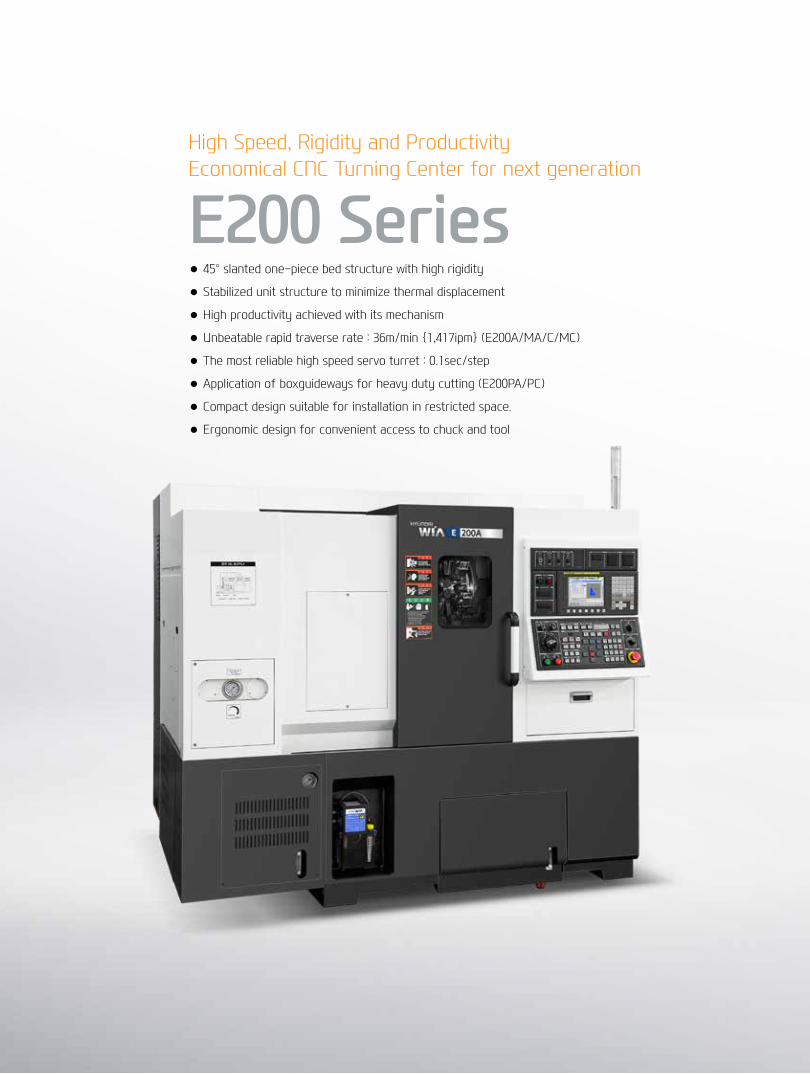
High Speed, Rigidity and ProductivityEconomical CNC Turning Center for next generation
E200 Series● 45° slanted one-piece bed structure with high rigidity
● Stabilized unit structure to minimize thermal displacement
● High productivity achieved with its mechanism
● Unbeatable rapid traverse rate : 36m/min {1,417ipm} (E200A/MA/C/MC)
● The most reliable high speed servo turret : 0.1sec/step
● Application of boxguideways for heavy duty cutting (E200PA/PC)
● Compact design suitable for installation in restricted space.
● Ergonomic design for convenient access to chuck and tool

01 Basic FeaturesThe Best Productivity 6 inch / 8 inch Compact CNC Turning CenterE200 Series
Main SpindleHeat produced by the main spindle is blocked by applying a symmetric one-piece base and an insulation plate. This enables maintenance of high accuracy even during a long period of machining.
TurretThe turret is driven by a servo motor at a remarkably high speed indexing time of 0.12sec/step. Cycle time is reduced and productivity is improved.
Ball ScrewIn order to eliminate thermal growth and increase accuracy, all axis are driven by high precision double anchored ballscrews.
High Precision, High Rigidity One-piece StructureThe E200 Series is designed with a 45 degree slanted bed combined with square type and tube type rib structure. This special design enhances rigidity and vibration absorbing capability, allowing powerful cutting with high precision.
01
04
0302
LM Guideway(E200A/MA/C/MC)
Box Guideway(E200PA/PC)
GuidewayE200A/C is designed with LM Guideways for all axes for better speed and response.
LM Guideway reduces non-cutting time and achieves a rapid traverse rate of 36m/min, which increases productivity.
E200PA/PC is designed with box guideways for all axes for stable heavy duty cutting.

◉ Rapid Traverse Rate (X/Z axis)
E200A | E200C | E200MA | E200MC : 36/36 m/min (1,417/1,417 ipm)
E200PA | E200PC : 24/24 m/min (945/945 ipm)
◉ Travel (X/Z axis)
E200A | E200C : 210/330 mm (8.3″/13″) E200MA | E200MC : 210/286 mm (8.3″/11.3″) E200PA | E200PC : 210/310 mm (8.3″/12.2″)
Reduction of non-cutting time by traverse rate
04+
05
E2
00 S
ERIE
SC
nC
Tu
rn
ing
Cen
Ter
HYu
nD
Ai W
iAM
ACH
ine
TOO
L
Basic Features
01
02
04
03

02 High Precision SpindleLong Lasting High Accuracy & Excellent PerformanceCNC Turning CenterE200 Series
Main SpindleThe spindle has a wide span of nominal production. The spindle structure is designed to minimize thermal displacement and perform high precision cutting during high speed and repeated cutting. By enlarging the spindle diameter and thickness, its rigidity is increased. Especially, high precision angular ball bearing designed spindle reduces noise and increases accuracy.
C-Axis ControlC-axis with BZ-Sensor performs 0.001°(Command) split angle and position control in order to process various products. (E200MA/MC)
0.001°
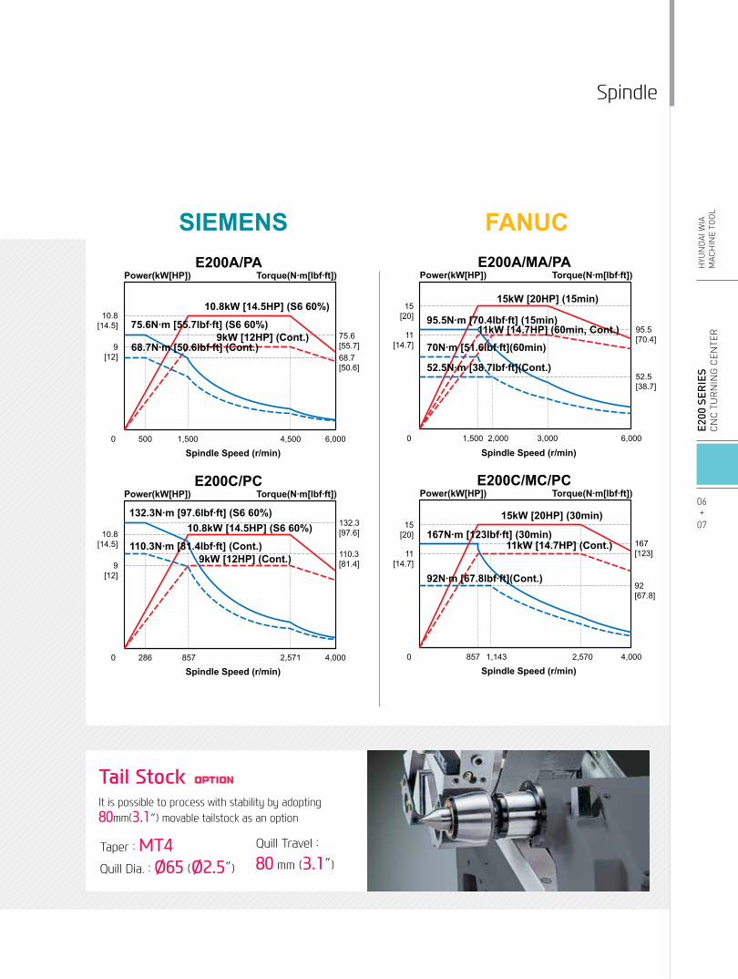
Tail StockIt is possible to process with stability by adopting 80mm(3.1″) movable tailstock as an option
Taper : MT4 Quill Dia. : Ø65 (Ø2.5″)
Quill Travel :
80 mm (3.1″)
Spindle
06+
07
E2
00 S
ERIE
SC
nC
Tu
rn
ing
Cen
Ter
HYu
nD
Ai W
iAM
ACH
ine
TOO
L
15kW [20HP] (15min)
Spindle Speed (r/min)
Spindle Speed (r/min)
95.5N∙m [70.4lbf∙ft] (15min)95.5[70.4]
15[20]
11[14.7]
15[20]
11[14.7]
15[20]
167[123]
92[67.8]
52.5[38.7]
52.5N∙m [38.7lbf∙ft](Cont.)
70N∙m [51.6lbf∙ft](60min)11kW [14.7HP] (60min, Cont.)
6,000
1,143 2,570
2,000 3,0001,500
15kW [20HP] (30min)
E200C/MC/PC
167N∙m [123lbf∙ft] (30min)
Power(kW[HP]) Torque(N∙m[lbf∙ft])
E200A/MA/PAPower(kW[HP]) Torque(N∙m[lbf∙ft])
92N∙m [67.8lbf∙ft](Cont.)
11kW [14.7HP] (Cont.)
Spindle Speed (r/min)
75.6[55.7]
10.8[14.5]
9[12] 68.7
[50.6]
1,500500 4,500 6,000
E200A/PAPower(kW[HP]) Torque(N∙m[lbf∙ft])
10.8kW [14.5HP] (S6 60%)
9kW [12HP] (Cont.)75.6N∙m [55.7lbf∙ft] (S6 60%)
68.7N∙m [50.6lbf∙ft] (Cont.)
Spindle Speed (r/min)
132.3[97.6]10.8
[14.5]
9[12]
110.3[81.4]
857286 2,571 4,000
E200C/PCPower(kW[HP]) Torque(N∙m[lbf∙ft])
10.8kW [14.5HP] (S6 60%)
9kW [12HP] (Cont.)
132.3N∙m [97.6lbf∙ft] (S6 60%)
110.3N∙m [81.4lbf∙ft] (Cont.)
Spindle Speed (r/min)
167[123]
206[152]
18.5[24.8]
2,000
18.5kW [24.8HP] (30min)
E200C
206N∙m [152lbf∙ft] (30min)
Power(kW[HP]) Torque(N∙m[lbf∙ft])
167N∙m [123lbf∙ft](Cont.)15kW [20HP] (Cont.)
FANUCSIEMENS

03 Servo TurretHigh speed, High Accuracy, Highly Reliable Servo Turret E200 Series
TurretThe E200 Series has a high performance AC servo motor and 3-piece coupling attached to the turret which enhances its process reliability. Powerful hydraulic tool clamping minimizes tool tip deviation which happens due to the load during heavy duty cutting.

08+
09
E2
00 S
ERIE
SC
nC
Tu
rn
ing
Cen
Ter
HYu
nD
Ai W
iAM
ACH
ine
TOO
L
Turret
Mill Tool HolderStraight Milling Head and Angular Milling Head live tools can be utilized to cut sides and inner diameters of workpieces.
Also, Drill, Tap, Endmill and many more tools can be utilized to enhance productivity and efficiency.
By adopting 3-piece coupling, it ensures powerful clamping and turret indexing and tool rotation is done by a single motor.
VDI method makes tool change easier and especially reduces tool change time so that it offers a great convenience.
Angular Milling HeadStraight Milling Head
Mill Turret (VDI)
◉ Number of Tools : 12 EA
◉ Tool Size (O.D/I.D) □25/Ø32 (□1″/Ø1.3″)
◉ Indexing Time : 0.12 sec/step
◉ Number of Tools : 12 EA
◉ Tool Size (O.D/I.D)
□25/Ø40 (□1″/Ø1.6″)
◉ Indexing Time : 0.12 sec/step
◉ Output (Max./Cont.) : 8.8/3 kW (11.8/4 HP)
◉ Speed : 4,500 rpm
◉ Collet size : Ø16 (Ø0.6″) (ER25)
◉ Type : VDI30
E200A | PA
E200C | PC
E200MA | MC (Mill Turret)

04 Machining CapabilityExcellent Performance, High Accuracy CuttingCNC Turning CenterE200 Series
10+
11
E2
00 S
ERIE
SC
nC
Tu
rn
ing
Cen
Ter
HYu
nD
Ai W
iAM
ACH
ine
TOO
L
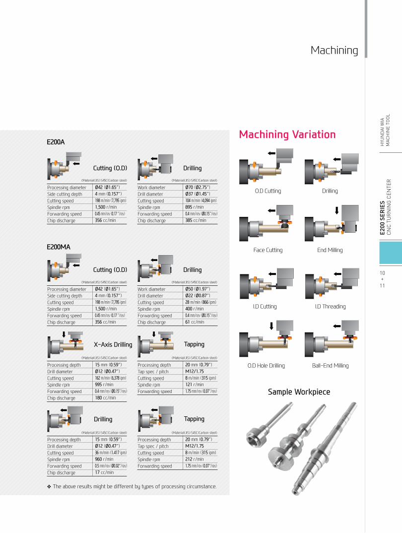
Machining
O.D Cutting
Face Cutting
Drilling
End Milling
I.D Cutting
O.D Hole Drilling
I.D Threading
Ball-End Milling
❖ The above results might be different by types of processing circumstance.
Machining Variation
Sample Workpiece
E200A
Processing diameterSide cutting depthCutting speedSpindle rpmForwarding speedChip discharge
Ø42 (Ø1.65″)4 mm (0.157″)198 m/min (7,795 ipm)1,500 r/min0.45 mm/rev (0.17 ″/rev)356 cc/min
Work diameterDrill diameterCutting speedSpindle rpmForwarding speedChip discharge
Ø70 (Ø2.75″)Ø37 (Ø1.45″)104 m/min (4,094 ipm)895 r/min0.4 mm/rev (Ø0.15″/rev)385 cc/min
DrillingCutting (O.D)
E200MA
Processing depthDrill diameterCutting speedSpindle rpmForwarding speedChip discharge
15 mm (0.59″)Ø12 (Ø0.47″)36 m/min (1.417 ipm)960 r/min0.5 mm/rev (Ø0.02″/rev)17 cc/min
Processing depthTap spec / pitchCutting speedSpindle rpmForwarding speed
20 mm (0.79″)M12/1.758 m/min (315 ipm)212 r/min1.75 mm/rev (0.07″/rev)
Drilling Tapping
Processing depthDrill diameterCutting speedSpindle rpmForwarding speedChip discharge
15 mm (0.59″)Ø12 (Ø0.47″)162 m/min (6,378 ipm)995 r/min0.4 mm/rev (Ø0.15″/rev)180 cc/min
Processing depthTap spec / pitchCutting speedSpindle rpmForwarding speed
20 mm (0.79″)M12/1.758 m/min (315 ipm)121 r/min1.75 mm/rev (0.07″/rev)
X-Axis Drilling Tapping
Processing diameterSide cutting depthCutting speedSpindle rpmForwarding speedChip discharge
Ø42 (Ø1.65″)4 mm (0.157″)198 m/min (7,795 ipm)1,500 r/min0.45 mm/rev (0.17 ″/rev)356 cc/min
Work diameterDrill diameterCutting speedSpindle rpmForwarding speedChip discharge
Ø50 (Ø1.97″)Ø22 (Ø0.87″)28 m/min (866 ipm)400 r/min0.4 mm/rev (Ø0.15″/rev)61 cc/min
DrillingCutting (O.D)
〈Material〈JIS〉:S45C(Carbon steel〉 〈Material〈JIS〉:S45C(Carbon steel〉
〈Material〈JIS〉:S45C(Carbon steel〉
〈Material〈JIS〉:S45C(Carbon steel〉 〈Material〈JIS〉:S45C(Carbon steel〉
〈Material〈JIS〉:S45C(Carbon steel〉
〈Material〈JIS〉:S45C(Carbon steel〉 〈Material〈JIS〉:S45C(Carbon steel〉
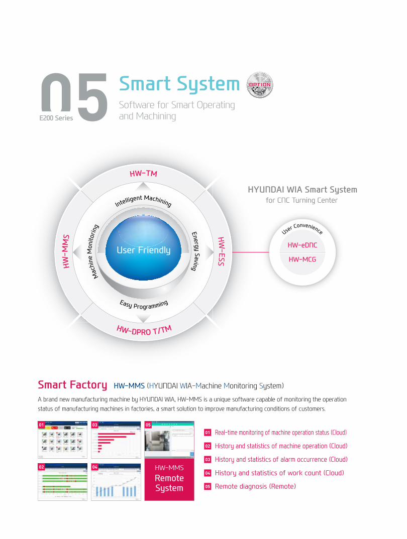
Machine Monitoring
Energy SavingIntelligent Machining
Easy Programming
HW-MMS HW
-ESS
HW-DPRO T/TM
User Friendly
HW-TM
HYUNDAI WIA Smart System for CNC Turning Center
User Convenience
HW-eDNC
HW-MCG
05 Smart SystemSoftware for Smart Operating and MachiningE200 Series
HW-MMS
RemoteSystem
Smart Factory HW-MMS (HYUNDAI WIA-Machine Monitoring System)
A brand new manufacturing machine by HYUNDAI WIA, HW-MMS is a unique software capable of monitoring the operation status of manufacturing machines in factories, a smart solution to improve manufacturing conditions of customers.
01 05
04
03
Real-time monitoring of machine operation status (Cloud)
History and statistics of machine operation (Cloud)
History and statistics of alarm occurrence (Cloud)
History and statistics of work count (Cloud)
Remote diagnosis (Remote)
01
05
04
03
02
02
12+
13
E2
00 S
ERIE
SC
nC
Tu
rn
ing
Cen
Ter
HYu
nD
Ai W
iAM
ACH
ine
TOO
L
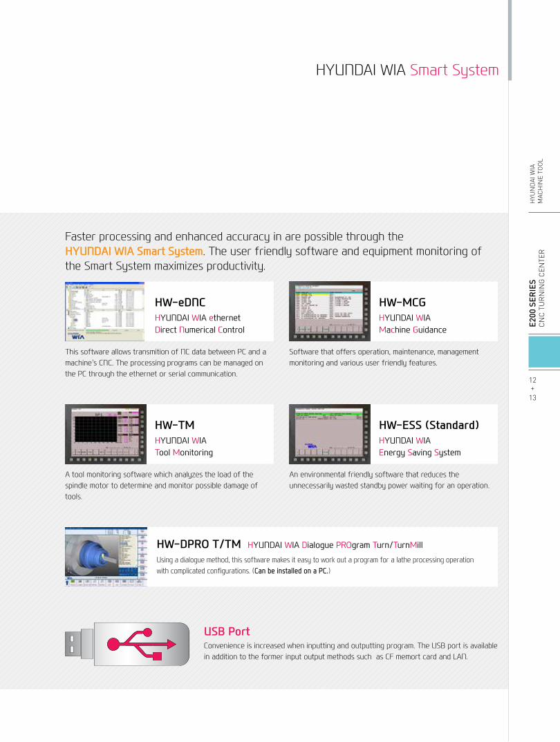
Faster processing and enhanced accuracy in are possible through the HYUNDAI WIA Smart System. The user friendly software and equipment monitoring of the Smart System maximizes productivity.
HW-DPRO T/TM HYUNDAI WIA Dialogue PROgram Turn/TurnMill
Using a dialogue method, this software makes it easy to work out a program for a lathe processing operation with complicated configurations. (Can be installed on a PC.)
USB PortConvenience is increased when inputting and outputting program. The USB port is available in addition to the former input output methods such as CF memort card and LAN.
HYUNDAI WIA Smart System
HW-eDNCHYUNDAI WIA ethernet Direct Numerical Control
This software allows transmition of NC data between PC and a machine's CNC. The processing programs can be managed on the PC through the ethernet or serial communication.
HW-MCGHYUNDAI WIAMachine Guidance
Software that offers operation, maintenance, management monitoring and various user friendly features.
HW-TMHYUNDAI WIA Tool Monitoring
A tool monitoring software which analyzes the load of the spindle motor to determine and monitor possible damage of tools.
HW-ESS (Standard)HYUNDAI WIAEnergy Saving System
An environmental friendly software that reduces the unnecessarily wasted standby power waiting for an operation.
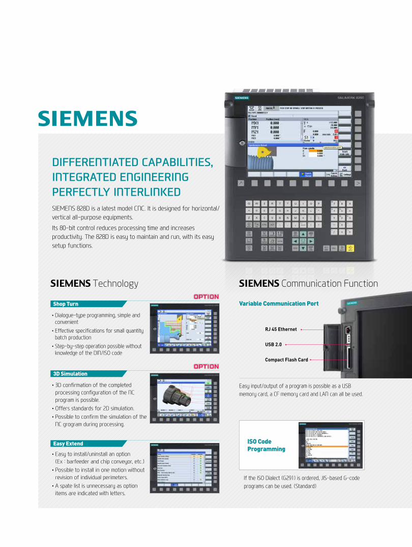
DIFFERENTIATED CAPABILITIES, INTEGRATED ENGINEERING PERFECTLY INTERLINKEDSIEMENS 828D is a latest model CNC. It is designed for horizontal/vertical all-purpose equipments.
Its 80-bit control reduces processing time and increases productivity. The 828D is easy to maintain and run, with its easy setup functions.
• Dialogue-type programming, simple and convenient
• Effective specifications for small quantity batch production
• Step-by-step operation possible without knowledge of the DIN/ISO code
Shop Turn
• 3D confirmation of the completed processing configuration of the NC program is possible.
•Offers standards for 2D simulation.• Possible to confirm the simulation of the
NC grogram during processing.
3D Simulation
• Easy to install/uninstall an option (Ex : barfeeder and chip conveyor, etc.)
• Possible to install in one motion without revision of individual perimeters.
• A spate list is unnecessary as option items are indicated with letters.
Easy Extend
Easy input/output of a program is possible as a USB memory card, a CF memory card and LAN can all be used.
RJ 45 Ethernet
USB 2.0
Compact Flash Card
Variable Communication Port
If the ISO Dialect (G291) is ordered, JIS-based G-code programs can be used. (Standard)
SIEMENS Technology SIEMENS Communication Function
ISO CodeProgramming
14+
15
E2
00 S
ERIE
SC
nC
Tu
rn
ing
Cen
Ter
HYu
nD
Ai W
iAM
ACH
ine
TOO
L
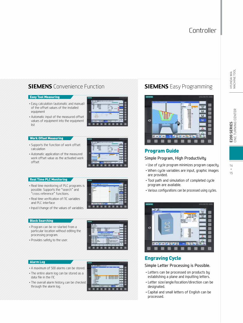
SIEMENS Convenience Function SIEMENS Easy Programming
• Easy calculation (automatic and manual) of the offset values of the installed equipment
• Automatic input of the measured offset values of equipment into the equipment list
Easy Tool Measuring
• Supports the function of work offset calculation
• Automatic application of the measured work offset value as the activated work offset
Work Offset Measuring
• Real time monitoring of PLC programs is possible. Supports the “search” and “cross reference” functions.
• Real time verification of NC variables and PLC interface
• Input/change of the values of variables
Real Time PLC Monitoring
• Program can be re-started from a particular location without editing the processing program.
• Provides safety to the user.
Block Searching
• A maximum of 500 alarms can be stored. • The entire alarm log can be stored as a
data file in the NC • The overall alarm history can be checked
through the alarm log.
Alarm Log
•Use of cycle program minimizes program capacity. • When cycle variables are input, graphic images
are provided. • Tool path and simulation of completed cycle
program are available. • Various configurations can be processed using cycles.
• Letters can be processed on products by establishing a plane and inputting letters.
• Letter size/angle/location/direction can be designated.
• Capital and small letters of English can be processed.
Program Guide Simple Program, High Productivity
Engraving CycleSimple Letter Processing is Possible.
Controller
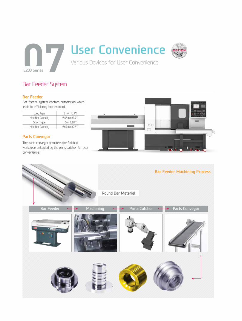
07 User ConvenienceVarious Devices for User Convenience
E200 Series
Parts ConveyorThe parts conveyor transfers the finished workpiece unloaded by the parts catcher for user convenience.
Bar Feeder System
Bar Feeder Bar feeder system enables automation which leads to efficiency improvement.
Round Bar Material
Bar Feeder Machining Parts Catcher Parts Conveyor
Bar Feeder Machining Process
Long Type 3 m (118.1″)Max Bar Capacity Ø42 mm (1.7″)
Short Type 1.5 m (59.1″)Max Bar Capacity Ø65 mm (2.6″)
E2
00 S
ERIE
SC
nC
Tu
rn
ing
Cen
Ter
HYu
nD
Ai W
iAM
ACH
ine
TOO
L
Optional
16+
17
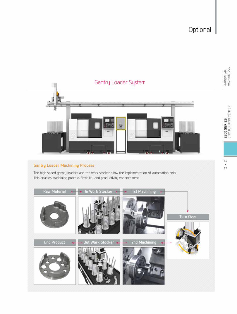
Gantry Loader System
Raw Material In Work Stocker 1st Machining
End Product Out Work Stocker 2nd Machining
The high speed gantry loaders and the work stocker allow the implementation of automation cells. This enables machining process flexibility and productivity enhancement.
Gantry Loader Machining Process
Turn Over

Spindle E200A/PA E200MA
Main SpindleHollow Chuck 3 Jaw
6″ ● ●8″ ○ ○
Main SpindleSolid Chuck 3 Jaw
6″ ○ ○8″ ☆ ☆
Standard Soft Jaw (1set) ● ●Chuck Clamp Foot Switch ● ●2 Steps Hyd, Pressure Device ○ ○Spindle Inside Stopper ☆ ☆5° Index ☆ -C-Axis (0.001°) - ●Chuck Open/Close Confirmation Device ○(CE:●) ○(CE:●)2 Steps Chuck Foot Switch ○ ○TurretTool Holder ● ●Mill Turret VDI - ●Straight Milling Head (Axial) Collet Type,1ea - ●Angular Milling Head (Radial) Collet Type,1ea - ●Straight Milling Head (Axial) Adapter Type - -Angular Milling Head (Radial) Adapter Type - -Boring Sleeve ● ●Drill Socket ● -U-Drill Holder ○ ○U-Drill Holder Sleeve ○ ○O.D Extension Holder For Outside Diameter ☆ -Swivel Head - ○Tail Stock & Steady RestQuill Type Tail Stock ○ ○Programmable Tail Stock - -Manual Type Hyd. Steady Rest - -Standard Live Center (Tail Stock : Standard) ○ ○High Precesion Live Center ○ ○2 Steps Tail Stock Pressure System ☆ ☆Quill Forward/Reverse Confirmation Device ○ ○Tail Stock Foot Switch ☆ ☆Coolant & Air BlowStandard Coolant (Nozzle) ● ●Chuck Coolant (Upper Chuck) ○ ○Gun Coolant ○ ○Through Spindle Coolant (Only for Special Chuck) ☆ ☆Thru Coolant for Live Tool - -Chuck Air Blow (Upper Chuck) ○ ○Tail Stock Air Blow (Upper Tail Stock) ☆ ☆Turret Air Blow ☆ ☆Air Gun ○ ○Through Spindle Air Blow (Only for Special Chuck) ☆ ☆
High Pressure Coolant0.4Bar (5.8 psi) ● ●6Bar (87 psi) ○ ○
Power Coolant System (For Automation) ☆ ☆Coolant Chiller ☆ ☆Chip DisposalCoolant Tank 135ℓ (35.7 gal) ● ●
Chip Conveyor(Hinge/Scraper)
Front(Rear) ○ ○Front (Right) ○ ○
Special Chip Conveyor (Drum Filter) ☆ ☆
Chip Wagon
Standard(180ℓ[47.5 gal]) ○ ○
Swing(200ℓ[52.8 gal]) ○ ○
Large Swing(290ℓ[76.6 gal]) ○ ○
Large Size(330ℓ[87.2 gal]) ○ ○
Customized ☆ ☆
Safety Device E200A/PA E200MA
Total Splash Guard ● ●Chuck hydraulic pressure maintenance interlock ○(CE:●) ○(CE:●)Electric DeviceCall Light 1 Color : ■ ● ●Call Light 2 Color : ■■ ○ ○Call Light 3 Color : ■■■ ○ ○Call Light & Buzzer 3 Color : ■■■B ○ ○Electric Cabinet Light ○ ○Remote MPG - -Work Counter Digital ○ ○Total Counter Digital ○ ○Tool Counter Digital ○ ○Multi Tool Counter Digital ○ ○Electric Circuit Breaker ○ ○AVR (Auto Voltage Regulator) ☆ ☆Transformer 20kVA ○ ○Auto Power Off ○ ○MeasurementQ-Setter ○ ○Automatic Q-Setter ○ ○
Work Close Confirmation Device(Only for Special Chuck)
TACO ○ ○SMC ○ ○
Work Setter ☆ ☆
Linear ScaleX axis - -Z axis - -
Coolant Level Sensor (Only for Chip Conveyor) ☆ ☆EnvironmentAir Conditioner ○ ○Oil Mist Collector ○ ○Oil Skimmer (Only for Chip Conveyor) ○ ○MQL (Minimal Quantity Lubrication) ☆ ☆Fixture & Automation Auto Door ○ ○Auto Shutter (Only for Automatic System) ☆ ☆Sub Operation Pannel ☆ ☆Bar Feeder Interface ○ ○Bar Feeder (FEDEK) ☆ ☆Work Pusher (Spring Type) ○ ○Extra M-Code 4ea ○ ○Automation Interface ☆ ☆
I/O Extension (IN & OUT)16 Contact ○ ○32 Contact ○ ○
Parts Catcher Main SP. ○ ○Turret Work Pusher (For Automation) ☆ ☆Parts Conveyor ☆ ☆Semi Automation System ☆ ☆Hyd. DeviceStandard Hyd. Cylinder Hollow ● ●
Standard Hyd. Unit 35bar (507.6 psi)/ 15ℓ (4 gal) ● ●
S/WMachine Guidance (HW-MCG) ☆ ☆Energy Saving System (HW-ESS) ● ●Tool Monitoring (HW-TM) ○ ○DNC software (HW-eDNC) ○ ○Machine Monitoring System (HW-MMS) ☆ ☆Conversational Program (HW-DPRO) ○ ○ETCTool Box ● ●Customized Color Need Munsel No. ☆ ☆CAD & CAM ☆ ☆
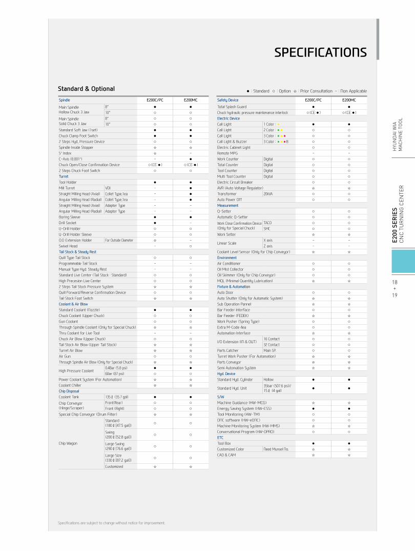
Standard & Optional ● : Standard ○ : Option ☆ : Prior Consultation - : Non Applicable
Specifications are subject to change without notice for improvement.
SPECIFICATIONS
Standard & Optional ● : Standard ○ : Option ☆ : Prior Consultation - : Non Applicable
Specifications are subject to change without notice for improvement.
18+
19
E2
00 S
ERIE
SC
nC
Tu
rn
ing
Cen
Ter
HYu
nD
Ai W
iAM
ACH
ine
TOO
L
SPECIFICATIONS
Spindle E200C/PC E200MC
Main SpindleHollow Chuck 3 Jaw
8″ ● ●10″ ○ ○
Main SpindleSolid Chuck 3 Jaw
8″ ○ ○10″ ○ ○
Standard Soft Jaw (1set) ● ●Chuck Clamp Foot Switch ● ●2 Steps Hyd, Pressure Device ○ ○Spindle Inside Stopper ☆ ☆5° Index ☆ -C-Axis (0.001°) - ●Chuck Open/Close Confirmation Device ○(CE:●) ○(CE:●)2 Steps Chuck Foot Switch ○ ○TurretTool Holder ● ●Mill Turret VDI - ●Straight Milling Head (Axial) Collet Type,1ea - ●Angular Milling Head (Radial) Collet Type,1ea - ●Straight Milling Head (Axial) Adapter Type - -Angular Milling Head (Radial) Adapter Type - -Boring Sleeve ● ●Drill Socket ● -U-Drill Holder ○ ○U-Drill Holder Sleeve ○ ○O.D Extension Holder For Outside Diameter ☆ -Swivel Head - ○Tail Stock & Steady RestQuill Type Tail Stock ○ ○Programmable Tail Stock - -Manual Type Hyd. Steady Rest - -Standard Live Center (Tail Stock : Standard) ○ ○High Precesion Live Center ○ ○2 Steps Tail Stock Pressure System ☆ ☆Quill Forward/Reverse Confirmation Device ○ ○Tail Stock Foot Switch ☆ ☆Coolant & Air BlowStandard Coolant (Nozzle) ● ●Chuck Coolant (Upper Chuck) ○ ○Gun Coolant ○ ○Through Spindle Coolant (Only for Special Chuck) ☆ ☆Thru Coolant for Live Tool - -Chuck Air Blow (Upper Chuck) ○ ○Tail Stock Air Blow (Upper Tail Stock) ☆ ☆Turret Air Blow ☆ ☆Air Gun ○ ○Through Spindle Air Blow (Only for Special Chuck) ☆ ☆
High Pressure Coolant0.4Bar (5.8 psi) ● ●6Bar (87 psi) ○ ○
Power Coolant System (For Automation) ☆ ☆Coolant Chiller ☆ ☆Chip DisposalCoolant Tank 135ℓ (35.7 gal) ● ●
Chip Conveyor(Hinge/Scraper)
Front(Rear) ○ ○Front (Right) ○ ○
Special Chip Conveyor (Drum Filter) ☆ ☆
Chip Wagon
Standard(180ℓ[47.5 gal]) ○ ○
Swing(200ℓ[52.8 gal]) ○ ○
Large Swing(290ℓ[76.6 gal]) ○ ○
Large Size(330ℓ[87.2 gal]) ○ ○
Customized ☆ ☆
Safety Device E200C/PC E200MC
Total Splash Guard ● ●Chuck hydraulic pressure maintenance interlock ○(CE:●) ○(CE:●)Electric DeviceCall Light 1 Color : ■ ● ●Call Light 2 Color : ■■ ○ ○Call Light 3 Color : ■■■ ○ ○Call Light & Buzzer 3 Color : ■■■B ○ ○Electric Cabinet Light ○ ○Remote MPG - -Work Counter Digital ○ ○Total Counter Digital ○ ○Tool Counter Digital ○ ○Multi Tool Counter Digital ○ ○Electric Circuit Breaker ○ ○AVR (Auto Voltage Regulator) ☆ ☆Transformer 20kVA ○ ○Auto Power Off ○ ○MeasurementQ-Setter ○ ○Automatic Q-Setter ○ ○
Work Close Confirmation Device(Only for Special Chuck)
TACO ○ ○SMC ○ ○
Work Setter ☆ ☆
Linear ScaleX axis - -Z axis - -
Coolant Level Sensor (Only for Chip Conveyor) ☆ ☆EnvironmentAir Conditioner ○ ○Oil Mist Collector ○ ○Oil Skimmer (Only for Chip Conveyor) ○ ○MQL (Minimal Quantity Lubrication) ☆ ☆Fixture & Automation Auto Door ○ ○Auto Shutter (Only for Automatic System) ☆ ☆Sub Operation Pannel ☆ ☆Bar Feeder Interface ○ ○Bar Feeder (FEDEK) ☆ ☆Work Pusher (Spring Type) ○ ○Extra M-Code 4ea ○ ○Automation Interface ☆ ☆
I/O Extension (IN & OUT)16 Contact ○ ○32 Contact ○ ○
Parts Catcher Main SP. ○ ○Turret Work Pusher (For Automation) ☆ ☆Parts Conveyor ☆ ☆Semi Automation System ☆ ☆Hyd. DeviceStandard Hyd. Cylinder Hollow ● ●
Standard Hyd. Unit 35bar (507.6 psi)/ 15ℓ (4 gal) ● ●
S/WMachine Guidance (HW-MCG) ☆ ☆Energy Saving System (HW-ESS) ● ●Tool Monitoring (HW-TM) ○ ○DNC software (HW-eDNC) ○ ○Machine Monitoring System (HW-MMS) ☆ ☆Conversational Program (HW-DPRO) ○ ○ETCTool Box ● ●Customized Color Need Munsel No. ☆ ☆CAD & CAM ☆ ☆

unit : mm(in)External Dimensions
SPECIFICATIONS
1443(56.8)577(22.7)
2020(79.5) 2050(80.7) 1260(49.6) 1230(48.4)
3280(129.1)
380(
14.9
)12
70(5
0)
2150
(84.
6)
500
R500
1000(39.3)
SPINDLE CENTER
1100(43.3)550(21.6)
1650(65)910(35.8)
2560(100.7)
10 (0.4
)66
5((2
6.2)
335
(13.
2)10
35(4
0.7)
110
(4.3
)11
45(4
5)67
5(26
.5)
1820
(71.
6)
380(14.9)
SPLINDLE CENTER
950(
37.4
)27
5(1
0.8)
192
(7.5
)12
24(4
8.1)
1416
(55.
7)
950(
37.4
)27
5(1
0.8)
192
(7.5
)12
24(4
8.1)
1416
(55.
7)
538(21.2)8(0.3)
920(36.2)933(36.7)
Ø16
9(6.
6)Ø
210(
8.2)
E200A/MA/PA E200C/MC/PC

12 Stations
VDI 3012 Stations
O.D Holder
I.D Holder
Boring BarSocket
Facing Holder
Face & I.DTool
Boring Bar
Drill
Boring BarBoring Bar
Socket
U-Drill Socket U-Drill Holder
Boring BarHolder Pice
Facing Holder
Face & I.D Tool
Boring BarØ32
Drill
U-Drill
Tap
End Mill
AngularMill Holder
Milling Collet
Tapping Collet
StraightMill Holder
Plug
unit : mm(in)Tooling System
20+
21
E2
00 S
ERIE
SC
nC
Tu
rn
ing
Cen
Ter
HYu
nD
Ai W
iAM
ACH
ine
TOO
L
SPECIFICATIONS
E200A/PAE200C/PC
Specifications are subject to change without notice for improvement.
Tooling Parts Detail
ITEME200A/PA E200C/PC
mm unit inch unit mm unit inch unit
Turning HolderO.D Holder Right/Left - - - -
Facing Holder 1 1 1 1
Boring Holder
I.D Holder Single 5 5 5 5
U-Drill HolderØ32 (1 1/4″) Opt - Opt -
Ø40 (1 1/2″) - Opt - Opt
Driven HolderStraight Mill Holder Standard - - - -
Angular Mill Holder Standard - - - -
Socket
Boring
Ø10 (Ø3/8″) 1 1 1 -
Ø12 (Ø1/2″) 1 1 1 1
Ø16 (Ø5/8″) 1 - 1 -
Ø20 (Ø3/4″) 1 1 1 1
Ø25 (Ø1″) - 1 1 1
Ø32 (Ø1 1/4″) - - 1 1
DrillMT 1 × MT 2 1 1 1 1
MT 2 1 1 1 1
ER Collet - - - -

unit : mm(in)Tooling System
SPECIFICATIONS
12 Stations
VDI 3012 Stations
O.D Holder
I.D Holder
Boring BarSocket
Facing Holder
Face & I.DTool
Boring Bar
Drill
Boring BarBoring Bar
Socket
U-Drill Socket U-Drill Holder
Boring BarHolder Pice
Facing Holder
Face & I.D Tool
Boring BarØ32
Drill
U-Drill
Tap
End Mill
AngularMill Holder
Milling Collet
Tapping Collet
StraightMill Holder
Plug
E200MAE200MC
Specifications are subject to change without notice for improvement.
Tooling Parts Detail
ITEME200MA E200MC
mm unit inch unit mm unit inch unit
Turning HolderO.D Holder Right/Left 4 4 4 4
Facing Holder 1 1 1 1
Boring Holder
I.D Holder Single 3 3 3 3
U-Drill HolderØ32 (Ø1 1/4″) - - - -
Ø40 (Ø1 1/2″) - - - -
Driven HolderStraight Mill Holder Standard 1 1 1 1
Angular Mill Holder Standard 1 1 1 1
Socket
Boring
Ø8 (Ø5/16″) 1 1 1 1
Ø10 (Ø3/8″) 1 1 1 1
Ø12 (Ø1/2″) 1 1 1 1
Ø16 (Ø5/8″) 1 1 1 1
Ø20 (Ø3/4″) 1 1 1 1
DrillMT 1 × MT 2 - - - -
MT 2 - - - -
ER Collet Opt Opt Opt Opt
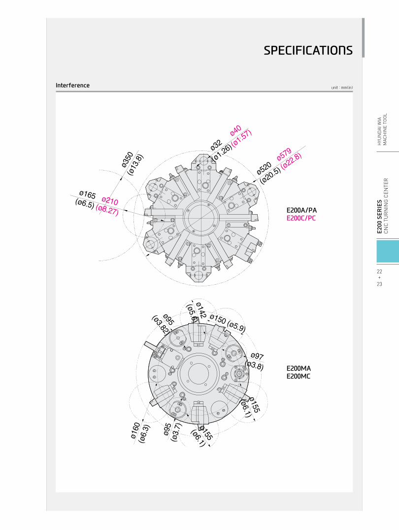
unit : mm(in)Interference
ø160
(ø6.
3) ø95
(ø3.
7) ø155
(ø6.1)
ø155
(ø6.1)
ø97(ø3.8)
ø150 (ø5.9)
ø142(ø5.6)ø95(ø3.82)
ø520
(ø20.5)ø579
(ø22.8)
ø165(ø6.5)ø210(ø8.27)
ø32
(ø1.26)ø40
(ø1.57)ø3
50(ø
13.8)
E200A/PAE200C/PC
E200MAE200MC
22+
23
E2
00 S
ERIE
SC
nC
Tu
rn
ing
Cen
Ter
HYu
nD
Ai W
iAM
ACH
ine
TOO
L
SPECIFICATIONS
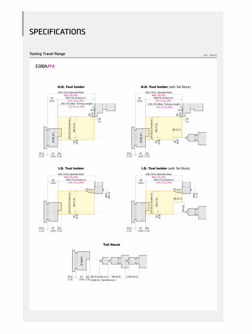
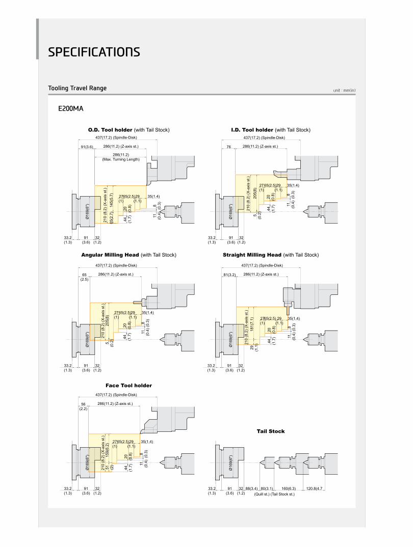
unit : mm(in)Tooling Travel Range
SPECIFICATIONS
20 (0.8
)
35 (3.4
)
7(0.3)
33.2(1.3)
25(1)
91(3.6)
32(1.2)
33.2(1.3)
91(3.6)
32(1.2)
Ø16
9 (6
")
20 (0.8
)19
0 (7
.5)
210
(8.2
) (X
-axi
s st
.)
20 (0.8
)19
0 (7
.5)
210
(8.2
) (X
-axi
s st
.)
91(3.6)
330 (13) (Max. Turning Length)
80 (3.1)
93(3.6)
Ø32
(Ø1.
3)
80 (3.1)
104
(4)
35 (3.4
)
7(0.3)
25(1)
20 (0.8
)19
0(7.
5)
210
(8.2
) (X
-axi
s st
.)
112(4.4)
53 (2.1
)15
7 (6
.2)
210
(8.2
) (X
-axi
s st
.)
Ø21
0 (8
")
Ø21
0 (8
")
40.1(1.5)
112(4.4)
39(1.5)
Ø21
0 (8
")
40.1(1.5)
112(4.4)
39(1.5)
20 (0.8
)19
0 (7
.5)
210
(8.2
) (X
-axi
s st
.)
25 (1)
20 (0.8
)
25(1)
55(2.2)
114 (4.5)
53 (2.1
)15
7 (6
.2)
210
(8.2
) (X
-axi
s st
.)
68 (2.7
)
Ø40
(1.6
)
90(3.5)
124
(4.9
)
33.2(1.3)
91(3.6)
32(1.2)
Ø16
9(6"
)
5(0
.2)
205(
8)
210
(8.2
) (X
-axi
s st
.)
76 286(11.2) (Z-axis st.)
437(17.2) (Spindle-Disk)
Ø16
9(6"
)
65(2
.7)
145(
5.7)
210
(8.2
) (X
-axi
s st
.)
91(3.6) 286(11.2) (Z-axis st.)
286(11.2)(Max. Turning Length)
437(17.2) (Spindle-Disk)
286(11.2) (Z-axis st.)
437(17.2) (Spindle-Disk)
286(11.2) (Z-axis st.)
437(17.2) (Spindle-Disk)
33.2(1.3)
91(3.6)
32(1.2)
Ø16
9(6"
)
33.2(1.3)
91(3.6)
32(1.2)
Ø16
9(6"
)
33.2(1.3)
91(3.6)
32(1.2)
35(1.4)29(1.1)
65(2.5)27(1)
44 (1.7
)20 (0.8
)
35(1.4)29(1.1)
65(2.5)27(1)
44 (1.7
)20 (0.8
)
11 (0.4
)8
(0.3
)
11 (0.4
)8
(0.3
)
5(0
.2)
205(
8)21
0 (8
.2) (
X-a
xis
st.)
65(2.5)
29 (1.1
)18
1(7.
1)21
0 (8
.2) (
X-a
xis
st.)
81(3.2) 286(11.2) (Z-axis st.)
437(17.2) (Spindle-Disk)
44 (1.7
)20 (0.8
)
11 (0.4
)8
(0.3
)
35(1.4)29(1.1)
65(2.5)27(1)
44 (1.7
)20 (0.8
)
11 (0.4
)8
(0.3
)
35(1.4)29(1.1)
65(2.5)27(1)
51 (2)
159(
6.2)
210
(8.2
) (X
-axi
s st
.)
56(2.2)
44 (1.7
)20 (0.8
)
11 (0.4
)8
(0.3
)
35(1.4)29(1.1)
65(2.5)27(1)
6514
521
0 (8
.2) (
X-a
xis
st.)
112(4.4)
458(18) (Spindle-Disk)
35(1.4)29(1.1)
65(2.5)27(1)
44 (1.7
)20 (0.8
)
11 (0.4
)8
(0.3
)
Ø21
0(8"
)
40.1(1.5)
112(4.4)
39(1.5)
Ø21
0(8"
)
40.1(1.5)
112(4.4)
39(1.5)
Ø21
0(8"
)
40.1(1.5)
112(4.4)
39(1.5)
97(3.8)
286(11.2) (Z-axis st.)
458(18) (Spindle-Disk)
Ø21
0(8"
)
40.1(1.5)
112(4.4)
39(1.5)
286(11.2) (Z-axis st.)
458(18) (spindle-disk)
Ø21
0(8"
)
40.1(1.5)
112(4.4)
39(1.5)
5(0
.2)
205
(8.1
)
210
(8.2
) (X
-axi
s st
.)
35(1.4)29(1.1)
65(2.5)27(1)
44 (1.7
)20 (0.8
)
11 (0.4
)8
(0.3
)
86(3.3)
520
5 (8
.1)
210
(8.2
) (X
-axi
s st
.)
44 (1.7
)20 (0.8
)
11 (0.4
)8
(0.3
)
35(1.4)29(1.1)
65(2.5)27(1)
102(4)
29 (1.1
)18
1 (7
.1)
210
(8.2
) (X
-axi
s st
.)
44 (1.7
)20 (0.8
)
11 (0.4
)8
(0.3
)
35(1.4)29(1.1)
65(2.5)27(1)
77(3)
51 (2)
159
(6.3
)21
0 (8
.2) (
X-a
xis
st.)
44 (1.7
)20 (0.8
)
11 (0.4
)8
(0.3
)
35(1.4)29(1.1)
65(2.5)27(1)
Ø16
9(6"
)
33.2(1.3)
91(3.6)
32(1.2)
88(3.4) 80(3.1) 160(6.3) 120.8(4.7(Quill st.) (Tail Stock st.)
Face Tool holder Face Tool holder
Tail Stock Tail Stock
Ø21
0(8"
)
40.1(1.5)
112(4.4)
39(1.5)
54.2(2.1)
80(3.1) 160(6.3) 120.8(4.7)
(Quill st.) (Tail Stock st.)
Ø16
9(6"
)
33.2(1.3)
91(3.6)
32(1.2)
88 (3.4) 80 (3.1) 160 (6.3) 120.8 (4.7)(Quill st.) (Tail Stock st.)
(Quill st.) (Tail Stock st.)
Tail Stock
Ø21
0(8"
)
40.1(1.5)
112(4.4)
39(1.5)
54.2(2.1)
80 (3.1) 160 (6.3) 120.8 (4.7)
428 (16.8) (Spindle-Disk)408 (16) (PA)
330 (13) (Z-axis st.)310 (12.2) (PA)
310 (12.2) (PA)
35 (3.4
)
7(0.3)
33.2(1.3)
25(1)
91(3.6)
32(1.2)
Ø16
9 (6
")
20 (0.8
)19
0 (7
.5)
210
(8.2
) (X
-axi
s st
.)
91(3.6)
330 (13) (Max. Turning Length)
428 (16.8) (Spindle-Disk)408 (16) (PA)
330(13) (Z-axis st.)310 (12.2) (PA)
310 (12.2) (PA)
428 (16.8) (Spindle-Disk)408 (16) (PA)
330 (13) (Z-axis st.)310 (12.2) (PA)
33.2(1.3)
91(3.6)
32(1.2)
20 (0.8
)19
0 (7
.5)
210
(8.2
) (X
-axi
s st
.)
93(3.6)
Ø32
(1.3
)
428 (16.8) (Spindle-Disk)408 (16) (PA)
330 (13) (Z-axis st.)310 (12.2) (PA)
449(17.6) (Spindle-Disk)429(16.8) (PC)
330(13) (Z-axis st.)310(12.2) (PC)
449 (17.6) (Spindle-Disk)429 (16.8) (PC)
330 (13) (Z-axis st.)310(12.2) (PC)
Ø21
0 (8
")
40.1(1.5)
112(4.4)
39(1.5)
114(4.5)
68 (2.7
)
Ø40
(1.6
)
449(17.6) (Spindle-Disk)429(16.8) (PC)
330(13) (Z-axis st.)310(12.2) (PC)
35 (3.4
)
7(0.3)
25(1)
112(4.4)
40.1(1.5)
112(4.4)
39(1.5)
449(17.6) (Spindle-Disk)429(16.8) (PC)
330(13) (Z-axis st.)310(12.2) (PC)
Ø16
9(6"
)
33.2(1.3)
91(3.6)
32(1.2)
286(11.2) (Z-axis st.)
458(18) (Spindle-Disk)
286(11.2) (Z-axis st.)
458(18) (Spindle-Disk)
286(11.2) (Z-axis st.)
O.D. Tool holder
I.D. Tool holder I.D. Tool holder (with Tail Stock)
O.D. Tool holder (with Tail Stock)
Tail Stock
O.D. Tool holder (with Tail Stock)
I.D. Tool holder (with Tail Stock)
O.D. Tool holder
I.D. Tool holder
O.D. Tool holder (with Tail Stock) I.D. Tool holder (with Tail Stock) O.D. Tool holder (with Tail Stock) I.D. Tool holder (with Tail Stock)
Straight Milling Head (with Tail Stock)Angular Milling Head (with Tail Stock)Straight Milling Head (with Tail Stock)Angular Milling Head (with Tail Stock)
E200A/PA

E200C/PC
20 (0.8
)
35 (3.4
)
7(0.3)
33.2(1.3)
25(1)
91(3.6)
32(1.2)
33.2(1.3)
91(3.6)
32(1.2)
Ø16
9 (6
")
20 (0.8
)19
0 (7
.5)
210
(8.2
) (X
-axi
s st
.)
20 (0.8
)19
0 (7
.5)
210
(8.2
) (X
-axi
s st
.)
91(3.6)
330 (13) (Max. Turning Length)
80 (3.1)
93(3.6)
Ø32
(Ø1.
3)
80 (3.1)
104
(4)
35 (3.4
)
7(0.3)
25(1)
20 (0.8
)19
0(7.
5)
210
(8.2
) (X
-axi
s st
.)
112(4.4)
53 (2.1
)15
7 (6
.2)
210
(8.2
) (X
-axi
s st
.)
Ø21
0 (8
")
Ø21
0 (8
")
40.1(1.5)
112(4.4)
39(1.5)
Ø21
0 (8
")
40.1(1.5)
112(4.4)
39(1.5)
20 (0.8
)19
0 (7
.5)
210
(8.2
) (X
-axi
s st
.)
25 (1)
20 (0.8
)
25(1)
55(2.2)
114 (4.5)
53 (2.1
)15
7 (6
.2)
210
(8.2
) (X
-axi
s st
.)
68 (2.7
)
Ø40
(1.6
)
90(3.5)
124
(4.9
)
33.2(1.3)
91(3.6)
32(1.2)
Ø16
9(6"
)
5(0
.2)
205(
8)
210
(8.2
) (X
-axi
s st
.)
76 286(11.2) (Z-axis st.)
437(17.2) (Spindle-Disk)
Ø16
9(6"
)
65(2
.7)
145(
5.7)
210
(8.2
) (X
-axi
s st
.)
91(3.6) 286(11.2) (Z-axis st.)
286(11.2)(Max. Turning Length)
437(17.2) (Spindle-Disk)
286(11.2) (Z-axis st.)
437(17.2) (Spindle-Disk)
286(11.2) (Z-axis st.)
437(17.2) (Spindle-Disk)
33.2(1.3)
91(3.6)
32(1.2)
Ø16
9(6"
)
33.2(1.3)
91(3.6)
32(1.2)
Ø16
9(6"
)
33.2(1.3)
91(3.6)
32(1.2)
35(1.4)29(1.1)
65(2.5)27(1)
44 (1.7
)20 (0.8
)
35(1.4)29(1.1)
65(2.5)27(1)
44 (1.7
)20 (0.8
)
11 (0.4
)8
(0.3
)
11 (0.4
)8
(0.3
)
5(0
.2)
205(
8)21
0 (8
.2) (
X-a
xis
st.)
65(2.5)
29 (1.1
)18
1(7.
1)21
0 (8
.2) (
X-a
xis
st.)
81(3.2) 286(11.2) (Z-axis st.)
437(17.2) (Spindle-Disk)
44 (1.7
)20 (0.8
)
11 (0.4
)8
(0.3
)
35(1.4)29(1.1)
65(2.5)27(1)
44 (1.7
)20 (0.8
)
11 (0.4
)8
(0.3
)
35(1.4)29(1.1)
65(2.5)27(1)
51 (2)
159(
6.2)
210
(8.2
) (X
-axi
s st
.)
56(2.2)
44 (1.7
)20 (0.8
)
11 (0.4
)8
(0.3
)
35(1.4)29(1.1)
65(2.5)27(1)
6514
521
0 (8
.2) (
X-a
xis
st.)
112(4.4)
458(18) (Spindle-Disk)
35(1.4)29(1.1)
65(2.5)27(1)
44 (1.7
)20 (0.8
)
11 (0.4
)8
(0.3
)
Ø21
0(8"
)
40.1(1.5)
112(4.4)
39(1.5)
Ø21
0(8"
)
40.1(1.5)
112(4.4)
39(1.5)
Ø21
0(8"
)
40.1(1.5)
112(4.4)
39(1.5)
97(3.8)
286(11.2) (Z-axis st.)
458(18) (Spindle-Disk)
Ø21
0(8"
)
40.1(1.5)
112(4.4)
39(1.5)
286(11.2) (Z-axis st.)
458(18) (spindle-disk)
Ø21
0(8"
)
40.1(1.5)
112(4.4)
39(1.5)
5(0
.2)
205
(8.1
)
210
(8.2
) (X
-axi
s st
.)
35(1.4)29(1.1)
65(2.5)27(1)
44 (1.7
)20 (0.8
)
11 (0.4
)8
(0.3
)
86(3.3)
520
5 (8
.1)
210
(8.2
) (X
-axi
s st
.)
44 (1.7
)20 (0.8
)
11 (0.4
)8
(0.3
)
35(1.4)29(1.1)
65(2.5)27(1)
102(4)
29 (1.1
)18
1 (7
.1)
210
(8.2
) (X
-axi
s st
.)
44 (1.7
)20 (0.8
)
11 (0.4
)8
(0.3
)
35(1.4)29(1.1)
65(2.5)27(1)
77(3)
51 (2)
159
(6.3
)21
0 (8
.2) (
X-a
xis
st.)
44 (1.7
)20 (0.8
)
11 (0.4
)8
(0.3
)
35(1.4)29(1.1)
65(2.5)27(1)
Ø16
9(6"
)
33.2(1.3)
91(3.6)
32(1.2)
88(3.4) 80(3.1) 160(6.3) 120.8(4.7(Quill st.) (Tail Stock st.)
Face Tool holder Face Tool holder
Tail Stock Tail Stock
Ø21
0(8"
)
40.1(1.5)
112(4.4)
39(1.5)
54.2(2.1)
80(3.1) 160(6.3) 120.8(4.7)
(Quill st.) (Tail Stock st.)
Ø16
9(6"
)
33.2(1.3)
91(3.6)
32(1.2)
88 (3.4) 80 (3.1) 160 (6.3) 120.8 (4.7)(Quill st.) (Tail Stock st.)
(Quill st.) (Tail Stock st.)
Tail Stock
Ø21
0(8"
)
40.1(1.5)
112(4.4)
39(1.5)
54.2(2.1)
80 (3.1) 160 (6.3) 120.8 (4.7)
428 (16.8) (Spindle-Disk)408 (16) (PA)
330 (13) (Z-axis st.)310 (12.2) (PA)
310 (12.2) (PA)
35 (3.4
)
7(0.3)
33.2(1.3)
25(1)
91(3.6)
32(1.2)
Ø16
9 (6
")
20 (0.8
)19
0 (7
.5)
210
(8.2
) (X
-axi
s st
.)
91(3.6)
330 (13) (Max. Turning Length)
428 (16.8) (Spindle-Disk)408 (16) (PA)
330(13) (Z-axis st.)310 (12.2) (PA)
310 (12.2) (PA)
428 (16.8) (Spindle-Disk)408 (16) (PA)
330 (13) (Z-axis st.)310 (12.2) (PA)
33.2(1.3)
91(3.6)
32(1.2)
20 (0.8
)19
0 (7
.5)
210
(8.2
) (X
-axi
s st
.)
93(3.6)
Ø32
(1.3
)
428 (16.8) (Spindle-Disk)408 (16) (PA)
330 (13) (Z-axis st.)310 (12.2) (PA)
449(17.6) (Spindle-Disk)429(16.8) (PC)
330(13) (Z-axis st.)310(12.2) (PC)
449 (17.6) (Spindle-Disk)429 (16.8) (PC)
330 (13) (Z-axis st.)310(12.2) (PC)
Ø21
0 (8
")
40.1(1.5)
112(4.4)
39(1.5)
114(4.5)
68 (2.7
)
Ø40
(1.6
)
449(17.6) (Spindle-Disk)429(16.8) (PC)
330(13) (Z-axis st.)310(12.2) (PC)
35 (3.4
)
7(0.3)
25(1)
112(4.4)
40.1(1.5)
112(4.4)
39(1.5)
449(17.6) (Spindle-Disk)429(16.8) (PC)
330(13) (Z-axis st.)310(12.2) (PC)
Ø16
9(6"
)
33.2(1.3)
91(3.6)
32(1.2)
286(11.2) (Z-axis st.)
458(18) (Spindle-Disk)
286(11.2) (Z-axis st.)
458(18) (Spindle-Disk)
286(11.2) (Z-axis st.)
O.D. Tool holder
I.D. Tool holder I.D. Tool holder (with Tail Stock)
O.D. Tool holder (with Tail Stock)
Tail Stock
O.D. Tool holder (with Tail Stock)
I.D. Tool holder (with Tail Stock)
O.D. Tool holder
I.D. Tool holder
O.D. Tool holder (with Tail Stock) I.D. Tool holder (with Tail Stock) O.D. Tool holder (with Tail Stock) I.D. Tool holder (with Tail Stock)
Straight Milling Head (with Tail Stock)Angular Milling Head (with Tail Stock)Straight Milling Head (with Tail Stock)Angular Milling Head (with Tail Stock)
unit : mm(in)Tooling Travel Range
SPECIFICATIONS
24+
25
E2
00 S
ERIE
SC
nC
Tu
rn
ing
Cen
Ter
HYu
nD
Ai W
iAM
ACH
ine
TOO
L
20 (0.8
)
35 (3.4
)
7(0.3)
33.2(1.3)
25(1)
91(3.6)
32(1.2)
33.2(1.3)
91(3.6)
32(1.2)
Ø16
9 (6
")
20 (0.8
)19
0 (7
.5)
210
(8.2
) (X
-axi
s st
.)
20 (0.8
)19
0 (7
.5)
210
(8.2
) (X
-axi
s st
.)
91(3.6)
330 (13) (Max. Turning Length)
80 (3.1)
93(3.6)
Ø32
(Ø1.
3)
80 (3.1)
104
(4)
35 (3.4
)
7(0.3)
25(1)
20 (0.8
)19
0(7.
5)
210
(8.2
) (X
-axi
s st
.)
112(4.4)
53 (2.1
)15
7 (6
.2)
210
(8.2
) (X
-axi
s st
.)
Ø21
0 (8
")
Ø21
0 (8
")
40.1(1.5)
112(4.4)
39(1.5)
Ø21
0 (8
")
40.1(1.5)
112(4.4)
39(1.5)
20 (0.8
)19
0 (7
.5)
210
(8.2
) (X
-axi
s st
.)
25 (1)
20 (0.8
)
25(1)
55(2.2)
114 (4.5)
53 (2.1
)15
7 (6
.2)
210
(8.2
) (X
-axi
s st
.)
68 (2.7
)
Ø40
(1.6
)
90(3.5)
124
(4.9
)
33.2(1.3)
91(3.6)
32(1.2)
Ø16
9(6"
)
5(0
.2)
205(
8)
210
(8.2
) (X
-axi
s st
.)
76 286(11.2) (Z-axis st.)
437(17.2) (Spindle-Disk)
Ø16
9(6"
)
65(2
.7)
145(
5.7)
210
(8.2
) (X
-axi
s st
.)
91(3.6) 286(11.2) (Z-axis st.)
286(11.2)(Max. Turning Length)
437(17.2) (Spindle-Disk)
286(11.2) (Z-axis st.)
437(17.2) (Spindle-Disk)
286(11.2) (Z-axis st.)
437(17.2) (Spindle-Disk)
33.2(1.3)
91(3.6)
32(1.2)
Ø16
9(6"
)
33.2(1.3)
91(3.6)
32(1.2)
Ø16
9(6"
)
33.2(1.3)
91(3.6)
32(1.2)
35(1.4)29(1.1)
65(2.5)27(1)
44 (1.7
)20 (0.8
)
35(1.4)29(1.1)
65(2.5)27(1)
44 (1.7
)20 (0.8
)
11 (0.4
)8
(0.3
)
11 (0.4
)8
(0.3
)
5(0
.2)
205(
8)21
0 (8
.2) (
X-a
xis
st.)
65(2.5)
29 (1.1
)18
1(7.
1)21
0 (8
.2) (
X-a
xis
st.)
81(3.2) 286(11.2) (Z-axis st.)
437(17.2) (Spindle-Disk)
44 (1.7
)20 (0.8
)
11 (0.4
)8
(0.3
)
35(1.4)29(1.1)
65(2.5)27(1)
44 (1.7
)20 (0.8
)
11 (0.4
)8
(0.3
)
35(1.4)29(1.1)
65(2.5)27(1)
51 (2)
159(
6.2)
210
(8.2
) (X
-axi
s st
.)
56(2.2)
44 (1.7
)20 (0.8
)
11 (0.4
)8
(0.3
)
35(1.4)29(1.1)
65(2.5)27(1)
6514
521
0 (8
.2) (
X-a
xis
st.)
112(4.4)
458(18) (Spindle-Disk)
35(1.4)29(1.1)
65(2.5)27(1)
44 (1.7
)20 (0.8
)
11 (0.4
)8
(0.3
)
Ø21
0(8"
)
40.1(1.5)
112(4.4)
39(1.5)
Ø21
0(8"
)
40.1(1.5)
112(4.4)
39(1.5)
Ø21
0(8"
)
40.1(1.5)
112(4.4)
39(1.5)
97(3.8)
286(11.2) (Z-axis st.)
458(18) (Spindle-Disk)
Ø21
0(8"
)
40.1(1.5)
112(4.4)
39(1.5)
286(11.2) (Z-axis st.)
458(18) (spindle-disk)
Ø21
0(8"
)
40.1(1.5)
112(4.4)
39(1.5)
5(0
.2)
205
(8.1
)
210
(8.2
) (X
-axi
s st
.)
35(1.4)29(1.1)
65(2.5)27(1)
44 (1.7
)20 (0.8
)
11 (0.4
)8
(0.3
)
86(3.3)
520
5 (8
.1)
210
(8.2
) (X
-axi
s st
.)
44 (1.7
)20 (0.8
)
11 (0.4
)8
(0.3
)
35(1.4)29(1.1)
65(2.5)27(1)
102(4)
29 (1.1
)18
1 (7
.1)
210
(8.2
) (X
-axi
s st
.)
44 (1.7
)20 (0.8
)
11 (0.4
)8
(0.3
)
35(1.4)29(1.1)
65(2.5)27(1)
77(3)
51 (2)
159
(6.3
)21
0 (8
.2) (
X-a
xis
st.)
44 (1.7
)20 (0.8
)
11 (0.4
)8
(0.3
)
35(1.4)29(1.1)
65(2.5)27(1)
Ø16
9(6"
)
33.2(1.3)
91(3.6)
32(1.2)
88(3.4) 80(3.1) 160(6.3) 120.8(4.7(Quill st.) (Tail Stock st.)
Face Tool holder Face Tool holder
Tail Stock Tail Stock
Ø21
0(8"
)
40.1(1.5)
112(4.4)
39(1.5)
54.2(2.1)
80(3.1) 160(6.3) 120.8(4.7)
(Quill st.) (Tail Stock st.)
Ø16
9(6"
)
33.2(1.3)
91(3.6)
32(1.2)
88 (3.4) 80 (3.1) 160 (6.3) 120.8 (4.7)(Quill st.) (Tail Stock st.)
(Quill st.) (Tail Stock st.)
Tail Stock
Ø21
0(8"
)
40.1(1.5)
112(4.4)
39(1.5)
54.2(2.1)
80 (3.1) 160 (6.3) 120.8 (4.7)
428 (16.8) (Spindle-Disk)408 (16) (PA)
330 (13) (Z-axis st.)310 (12.2) (PA)
310 (12.2) (PA)
35 (3.4
)
7(0.3)
33.2(1.3)
25(1)
91(3.6)
32(1.2)
Ø16
9 (6
")
20 (0.8
)19
0 (7
.5)
210
(8.2
) (X
-axi
s st
.)
91(3.6)
330 (13) (Max. Turning Length)
428 (16.8) (Spindle-Disk)408 (16) (PA)
330(13) (Z-axis st.)310 (12.2) (PA)
310 (12.2) (PA)
428 (16.8) (Spindle-Disk)408 (16) (PA)
330 (13) (Z-axis st.)310 (12.2) (PA)
33.2(1.3)
91(3.6)
32(1.2)
20 (0.8
)19
0 (7
.5)
210
(8.2
) (X
-axi
s st
.)
93(3.6)
Ø32
(1.3
)
428 (16.8) (Spindle-Disk)408 (16) (PA)
330 (13) (Z-axis st.)310 (12.2) (PA)
449(17.6) (Spindle-Disk)429(16.8) (PC)
330(13) (Z-axis st.)310(12.2) (PC)
449 (17.6) (Spindle-Disk)429 (16.8) (PC)
330 (13) (Z-axis st.)310(12.2) (PC)
Ø21
0 (8
")
40.1(1.5)
112(4.4)
39(1.5)
114(4.5)
68 (2.7
)
Ø40
(1.6
)
449(17.6) (Spindle-Disk)429(16.8) (PC)
330(13) (Z-axis st.)310(12.2) (PC)
35 (3.4
)
7(0.3)
25(1)
112(4.4)
40.1(1.5)
112(4.4)
39(1.5)
449(17.6) (Spindle-Disk)429(16.8) (PC)
330(13) (Z-axis st.)310(12.2) (PC)
Ø16
9(6"
)
33.2(1.3)
91(3.6)
32(1.2)
286(11.2) (Z-axis st.)
458(18) (Spindle-Disk)
286(11.2) (Z-axis st.)
458(18) (Spindle-Disk)
286(11.2) (Z-axis st.)
O.D. Tool holder
I.D. Tool holder I.D. Tool holder (with Tail Stock)
O.D. Tool holder (with Tail Stock)
Tail Stock
O.D. Tool holder (with Tail Stock)
I.D. Tool holder (with Tail Stock)
O.D. Tool holder
I.D. Tool holder
O.D. Tool holder (with Tail Stock) I.D. Tool holder (with Tail Stock) O.D. Tool holder (with Tail Stock) I.D. Tool holder (with Tail Stock)
Straight Milling Head (with Tail Stock)Angular Milling Head (with Tail Stock)Straight Milling Head (with Tail Stock)Angular Milling Head (with Tail Stock)
E200MA
unit : mm(in)Tooling Travel Range
SPECIFICATIONS

20 (0.8
)
35 (3.4
)
7(0.3)
33.2(1.3)
25(1)
91(3.6)
32(1.2)
33.2(1.3)
91(3.6)
32(1.2)
Ø16
9 (6
")
20 (0.8
)19
0 (7
.5)
210
(8.2
) (X
-axi
s st
.)
20 (0.8
)19
0 (7
.5)
210
(8.2
) (X
-axi
s st
.)
91(3.6)
330 (13) (Max. Turning Length)
80 (3.1)
93(3.6)
Ø32
(Ø1.
3)
80 (3.1)
104
(4)
35 (3.4
)
7(0.3)
25(1)
20 (0.8
)19
0(7.
5)
210
(8.2
) (X
-axi
s st
.)
112(4.4)
53 (2.1
)15
7 (6
.2)
210
(8.2
) (X
-axi
s st
.)
Ø21
0 (8
")
Ø21
0 (8
")
40.1(1.5)
112(4.4)
39(1.5)
Ø21
0 (8
")
40.1(1.5)
112(4.4)
39(1.5)
20 (0.8
)19
0 (7
.5)
210
(8.2
) (X
-axi
s st
.)
25 (1)
20 (0.8
)
25(1)
55(2.2)
114 (4.5)
53 (2.1
)15
7 (6
.2)
210
(8.2
) (X
-axi
s st
.)
68 (2.7
)
Ø40
(1.6
)
90(3.5)
124
(4.9
)
33.2(1.3)
91(3.6)
32(1.2)
Ø16
9(6"
)
5(0
.2)
205(
8)
210
(8.2
) (X
-axi
s st
.)
76 286(11.2) (Z-axis st.)
437(17.2) (Spindle-Disk)
Ø16
9(6"
)
65(2
.7)
145(
5.7)
210
(8.2
) (X
-axi
s st
.)
91(3.6) 286(11.2) (Z-axis st.)
286(11.2)(Max. Turning Length)
437(17.2) (Spindle-Disk)
286(11.2) (Z-axis st.)
437(17.2) (Spindle-Disk)
286(11.2) (Z-axis st.)
437(17.2) (Spindle-Disk)
33.2(1.3)
91(3.6)
32(1.2)
Ø16
9(6"
)
33.2(1.3)
91(3.6)
32(1.2)
Ø16
9(6"
)
33.2(1.3)
91(3.6)
32(1.2)
35(1.4)29(1.1)
65(2.5)27(1)
44 (1.7
)20 (0.8
)
35(1.4)29(1.1)
65(2.5)27(1)
44 (1.7
)20 (0.8
)
11 (0.4
)8
(0.3
)
11 (0.4
)8
(0.3
)
5(0
.2)
205(
8)21
0 (8
.2) (
X-a
xis
st.)
65(2.5)
29 (1.1
)18
1(7.
1)21
0 (8
.2) (
X-a
xis
st.)
81(3.2) 286(11.2) (Z-axis st.)
437(17.2) (Spindle-Disk)
44 (1.7
)20 (0.8
)
11 (0.4
)8
(0.3
)
35(1.4)29(1.1)
65(2.5)27(1)
44 (1.7
)20 (0.8
)
11 (0.4
)8
(0.3
)
35(1.4)29(1.1)
65(2.5)27(1)
51 (2)
159(
6.2)
210
(8.2
) (X
-axi
s st
.)
56(2.2)
44 (1.7
)20 (0.8
)
11 (0.4
)8
(0.3
)
35(1.4)29(1.1)
65(2.5)27(1)
6514
521
0 (8
.2) (
X-a
xis
st.)
112(4.4)
458(18) (Spindle-Disk)
35(1.4)29(1.1)
65(2.5)27(1)
44 (1.7
)20 (0.8
)
11 (0.4
)8
(0.3
)
Ø21
0(8"
)
40.1(1.5)
112(4.4)
39(1.5)
Ø21
0(8"
)
40.1(1.5)
112(4.4)
39(1.5)
Ø21
0(8"
)
40.1(1.5)
112(4.4)
39(1.5)
97(3.8)
286(11.2) (Z-axis st.)
458(18) (Spindle-Disk)
Ø21
0(8"
)40.1(1.5)
112(4.4)
39(1.5)
286(11.2) (Z-axis st.)
458(18) (spindle-disk)
Ø21
0(8"
)
40.1(1.5)
112(4.4)
39(1.5)
5(0
.2)
205
(8.1
)
210
(8.2
) (X
-axi
s st
.)
35(1.4)29(1.1)
65(2.5)27(1)
44 (1.7
)20 (0.8
)
11 (0.4
)8
(0.3
)
86(3.3)
520
5 (8
.1)
210
(8.2
) (X
-axi
s st
.)
44 (1.7
)20 (0.8
)
11 (0.4
)8
(0.3
)
35(1.4)29(1.1)
65(2.5)27(1)
102(4)
29 (1.1
)18
1 (7
.1)
210
(8.2
) (X
-axi
s st
.)
44 (1.7
)20 (0.8
)
11 (0.4
)8
(0.3
)
35(1.4)29(1.1)
65(2.5)27(1)
77(3)
51 (2)
159
(6.3
)21
0 (8
.2) (
X-a
xis
st.)
44 (1.7
)20 (0.8
)
11 (0.4
)8
(0.3
)
35(1.4)29(1.1)
65(2.5)27(1)
Ø16
9(6"
)
33.2(1.3)
91(3.6)
32(1.2)
88(3.4) 80(3.1) 160(6.3) 120.8(4.7(Quill st.) (Tail Stock st.)
Face Tool holder Face Tool holder
Tail Stock Tail Stock
Ø21
0(8"
)
40.1(1.5)
112(4.4)
39(1.5)
54.2(2.1)
80(3.1) 160(6.3) 120.8(4.7)
(Quill st.) (Tail Stock st.)
Ø16
9(6"
)
33.2(1.3)
91(3.6)
32(1.2)
88 (3.4) 80 (3.1) 160 (6.3) 120.8 (4.7)(Quill st.) (Tail Stock st.)
(Quill st.) (Tail Stock st.)
Tail Stock
Ø21
0(8"
)
40.1(1.5)
112(4.4)
39(1.5)
54.2(2.1)
80 (3.1) 160 (6.3) 120.8 (4.7)
428 (16.8) (Spindle-Disk)408 (16) (PA)
330 (13) (Z-axis st.)310 (12.2) (PA)
310 (12.2) (PA)
35 (3.4
)
7(0.3)
33.2(1.3)
25(1)
91(3.6)
32(1.2)
Ø16
9 (6
")
20 (0.8
)19
0 (7
.5)
210
(8.2
) (X
-axi
s st
.)
91(3.6)
330 (13) (Max. Turning Length)
428 (16.8) (Spindle-Disk)408 (16) (PA)
330(13) (Z-axis st.)310 (12.2) (PA)
310 (12.2) (PA)
428 (16.8) (Spindle-Disk)408 (16) (PA)
330 (13) (Z-axis st.)310 (12.2) (PA)
33.2(1.3)
91(3.6)
32(1.2)
20 (0.8
)19
0 (7
.5)
210
(8.2
) (X
-axi
s st
.)
93(3.6)
Ø32
(1.3
)
428 (16.8) (Spindle-Disk)408 (16) (PA)
330 (13) (Z-axis st.)310 (12.2) (PA)
449(17.6) (Spindle-Disk)429(16.8) (PC)
330(13) (Z-axis st.)310(12.2) (PC)
449 (17.6) (Spindle-Disk)429 (16.8) (PC)
330 (13) (Z-axis st.)310(12.2) (PC)
Ø21
0 (8
")
40.1(1.5)
112(4.4)
39(1.5)
114(4.5)
68 (2.7
)
Ø40
(1.6
)
449(17.6) (Spindle-Disk)429(16.8) (PC)
330(13) (Z-axis st.)310(12.2) (PC)
35 (3.4
)
7(0.3)
25(1)
112(4.4)
40.1(1.5)
112(4.4)
39(1.5)
449(17.6) (Spindle-Disk)429(16.8) (PC)
330(13) (Z-axis st.)310(12.2) (PC)
Ø16
9(6"
)
33.2(1.3)
91(3.6)
32(1.2)
286(11.2) (Z-axis st.)
458(18) (Spindle-Disk)
286(11.2) (Z-axis st.)
458(18) (Spindle-Disk)
286(11.2) (Z-axis st.)
O.D. Tool holder
I.D. Tool holder I.D. Tool holder (with Tail Stock)
O.D. Tool holder (with Tail Stock)
Tail Stock
O.D. Tool holder (with Tail Stock)
I.D. Tool holder (with Tail Stock)
O.D. Tool holder
I.D. Tool holder
O.D. Tool holder (with Tail Stock) I.D. Tool holder (with Tail Stock) O.D. Tool holder (with Tail Stock) I.D. Tool holder (with Tail Stock)
Straight Milling Head (with Tail Stock)Angular Milling Head (with Tail Stock)Straight Milling Head (with Tail Stock)Angular Milling Head (with Tail Stock)
E200MC
unit : mm(in)Tooling Travel Range
SPECIFICATIONS
26+
27
E2
00 S
ERIE
SC
nC
Tu
rn
ing
Cen
Ter
HYu
nD
Ai W
iAM
ACH
ine
TOO
L
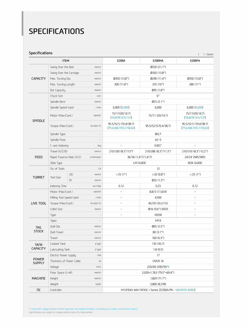
Specifications [ ] : Option
ITEM E200A E200MA E200PA
CAPACITY
Swing Over the Bed mm(in) Ø550 (21.7″)
Swing Over the Carriage mm(in) Ø350 (13.8″)
Max. Turning Dia. mm(in) Ø350 (13.8″) Ø290 (11.4″) Ø350 (13.8″)
Max. Turning Length mm(in) 300 (11.8″) 255 (10″) 280 (11″)
Bar Capacity mm(in) Ø45 (1.8″)
SPINDLE
Chuck Size inch 6″
Spindle Bore mm(in) Ø53 (2.1″)
Spindle Speed (rpm) r/min 6,000 [6,000] 6,000 6,000 [6,000]
Motor (Max/Cont.) kW(HP)15/11(20/14.7)
[10.8/9(14.5/12)]15/11 (20/14.7)
15/11(20/14.7)[10.8/9(14.5/12)]
Torque (Max/Cont.) N・m(lbf・ft)95.5/52.5 (70.4/38.7)[75.6/68.7(55.7/50.6)]
95.5/52.5(70.4/38.7)95.5/52.5 (70.4/38.7)[75.6/68.7(55.7/50.6)]
Spindle Type - BELT
Spindle Nose - A2-5
C-axis Indexing deg - 0.001˚ -
FEED
Travel (X/Z/B) mm(in) 210/330 (8.3″/13″) 210/286 (8.3″/11.3″) 210/310 (8.3″/12.2″)
Rapid Traverse Rate (X/Z) m/min(ipm) 36/36 (1,417/1,417) 24/24 {945/945)
Slide Type - LM GUIDE BOX GUIDE
TURRET
No. of Tools EA 12
Tool SizeOD mm(in) □25 (1″) □20 (0.8″) □25 (1″)
ID mm(in) Ø32 (1.3″)
Indexing Time sec/step 0.12 0.23 0.12
LIVE TOOL
Motor (Max/Cont.) kW(HP) - 8.8/3 (11.8/4) -
Milling Tool Speed (rpm) r/min - 4,500 -
Torque (Max/Cont.) N・m(lbf・ft) - 45/20 (33.2/15) -
Collet Size mm(in) - Ø16 (0.6″) ER25 -
Type - - VDI30 -
TAIL STOCK
Taper - MT4
Quill Dia. mm(in) Ø65 (2.5″)
Quill Travel mm(in) 80 (3.1″)
Travel mm(in) 160 (6.3″)
TANKCAPACITY
Coolant Tank ℓ(gal) 135 (35.7)
Lubricating Tank ℓ(gal) 1.8 (0.5)
POWERSUPPLY
Electric Power Supply kVA 17
Thickness of Power Cable Sq OVER 16
Voltage V/Hz 220/60 (200/50*)
MACHINE
Floor Space (L×W) mm(in) 2,020×1,763 (79.5″×69.4″)
Height mm(in) 1,820 (71.7″)
Weight kg(lb) 3,800 (8,378)
NC Controller - HYUNDAI WIA FANUC i Series [E200A/PA : SIEMENS 828D]
SPECIFICATIONS
*) Using 50Hz voltage instead of 60Hz may lower the output of motors. (excluding servo motors and inverter motors)Specifications are subject to change without notice for improvement.

Specifications [ ] : Option
ITEM E200C E200MC E200PC
CAPACITY
Swing Over the Bed mm(in) Ø550 (21.7″)
Swing Over the Carriage mm(in) Ø350 (13.8″)
Max. Turning Dia. mm(in) Ø350 (13.8″) Ø290 (11.4″) Ø350 (13.8″)
Max. Turning Length mm(in) 270 (10.6″) 255 (10″) 270 (10.6″)
Bar Capacity mm(in) Ø65 (2.6″)
SPINDLE
Chuck Size inch 8″
Spindle Bore mm(in) Ø78 (3.1″)
Spindle Speed (rpm) r/min 4,000 [4,000] 4,000 4,000 [4,000]
Motor (Max/Cont.) kW(HP)15/11(20/14.7)
[10.8/9(14.5/12)]15/11 (20/14.7)
15/11(20/14.7)[10.8/9(14.5/12)]
Torque (Max/Cont.) N・m(lbf・ft)167/92 (123.1/67.8)
[132.3/110.3 (97.5/81.3)]167/92 (123.1/67.8)
167/92 (123.1/67.8)[132.3/110.3 (97.5/81.3)]
Spindle Type - BELT
Spindle Nose - A2-6
C-axis Indexing deg - 0.001˚ -
FEED
Travel (X/Z/B) mm(in) 210/330 (8.3″/13″) 210/286 (8.3″/11.3″) 210/310 (8.3″/12.2″)
Rapid Traverse Rate (X/Z) m/min(ipm) 36/36 (1,417/1,417) 24/24 {945/945)
Slide Type - LM GUIDE BOX GUIDE
TURRET
No. of Tools EA 12
Tool SizeOD mm(in) □25 (1″) □20 (0.8″) □25 (1″)
ID mm(in) Ø40 (1.6″) Ø32 (1.3″) Ø40 (1.6″)
Indexing Time sec/step 0.12 0.23 0.12
LIVE TOOL
Motor (Max/Cont.) kW(HP) - 8.8/3 (11.8/4) -
Milling Tool Speed (rpm) r/min - 4,500 -
Torque (Max/Cont.) N・m(lbf・ft) - 45/20 (33.2/15) -
Collet Size mm(in) - Ø16 (0.6″) ER25 -
Type - - VDI30 -
TAIL STOCK
Taper - MT4
Quill Dia. mm(in) Ø65 (2.5″)
Quill Travel mm(in) 80 (3.1″)
Travel mm(in) 160 (6.3″)
TANKCAPACITY
Coolant Tank ℓ(gal) 135 (35.7)
Lubricating Tank ℓ(gal) 1.8 (0.5)
POWERSUPPLY
Electric Power Supply kVA 17
Thickness of Power Cable Sq OVER 16
Voltage V/Hz 220/60 (200/50*)
MACHINE
Floor Space (L×W) mm(in) 2,050×1,763 (80.7″×69.4″)
Height mm(in) 1,820 (71.7″)
Weight kg(lb) 3,800 (8,378)
NC Controller - HYUNDAI WIA FANUC i Series [E200C/PC : SIEMENS 828D]
SPECIFICATIONS
28+
29
E2
00 S
ERIE
SC
nC
Tu
rn
ing
Cen
Ter
HYu
nD
Ai W
iAM
ACH
ine
TOO
L
*) Using 50Hz voltage instead of 60Hz may lower the output of motors. (excluding servo motors and inverter motors)Specifications are subject to change without notice for improvement.

CONTROLLER
HYUNDAI WIA FANUC i Series [ ] : Option
Controlled axis / Display / Accuracy Compensation
Control axes2 axes (X, Z) / 3 axes (X, Z, C / X, Z, B) / 4 axes (X, Z, Y, C)5 axes (X, Z, B, C, A) / 6 axes (X, Z, Y, B, C, A)
Simultaneously controlled axes 2 axes [Max. 4 axes]Designation of spindle axes 3 axes (1 path)
Least setting UnitX, Z, Y, B axes : 0.001 mm (0.0001 inch)C, A axes : 0.001 deg
Least input incrementX, Z, Y, B axes : 0.001 mm (0.0001 inch)C, A axes : 0.001 deg
Inch / Metric conversion G20 / G21 High response vector controlInterlock All axes / Each axisMachine lock All axes
Backlash compensation ± 0 ~ 9999 pulses(Rapid traverse / Cutting feed)
Position switchLCD / MDI 8.4 inch / 10.4 inch color LCD Feedback Absolute motor feedback Stored stroke check 1 Over travel Stored stroke check 2, 3PMC axis controlOperationAutomatic operation (Memory)MDI operationDNC operation Needed DNC software / CF cardProgram restartWrong operation preventionProgram check function Dry runSingle blockSearch function Program Number / Sequence NumberInterpolation functionsNano interpolationPositioning G00 Linear interpolation G01 Circular interpolation G02, G03 Exact stop mode Single : G09, Continuous : G61Dwell G04, 0 ~ 9999.9999 sec Skip G31
Reference position return1st reference : G282nd reference : G30Ref. position check : G27
Thread synchronous cuttingThread cutting retractVariable lead thread cuttingMulti / Continuous threadingFeed function / Acc. & Dec. control
Manual feed
Rapid traverseJog : 0~2,000 mm/min (79 ipm)Manual handle : x1, x10, x100 pulsesReference position return
Cutting Feed command Direct input F codeFeedrate override 0 ~ 200% (10% Unit)Rapid traverse override F1%, F5%, F25% / 50%, F100% Override cancelFeed per minute G98 Feed per revolution G99 Look-ahead block 1 blockProgram inputTape Code EIA / ISO Optional block skip 1 ea Absolute / Incremental program G90 / G91 Program stop / end M00, M01 / M02, M30 Maximum command unit ± 999,999.999 mm (± 99,999.9999 inch)Plane selection X-Y : G17 / Z-X : G18 / Y-Z : G19Workpiece coordinate system G52, G53, 6 pairs (G54 ~ G59) Manual absolute Fixed ONProgrammable data input G10 Sub program call 10 folds nestedCustom macro #100 ~ #149, #500 ~ #549 G code system A Programmable mirror image G51.1, G50.1 G code preventing buffering G4.1 Direct drawing dimension program Including Chamfering / Corner R
Program inputMultiple repetitive cycles Ⅰ, ⅡCanned cycle for turningAuxiliary function / Spindle speed functionAuxiliary function M & 4 digitLevel-up M Code High speed / Multi / Bypass M codeSpindle speed function S & 4 digit , Binary outputSpindle override 0% ~ 150% (10% Unit)Multi position spindle orientation M19FSSB high speed rigid tappingConstant surface speed control G96, G97 Tool function / Tool compensationTool function T & 2 digit + Offset 2 digitTool life managementTool offset pairs 128 pairsTool nose radius compensation G40, G41, G42Geometry / Wear compensationDirect input of offset measured BEditing functionPart program storage size 1280m (512KB)No. of registerable programs 1000 ea Program protectBackground editingExtended part program editing Copy, move and change of NC programMemory card program editData input / output & Interface
I/O interfaceRS 232C serial port, CF card, USB memoryEmbedded Ethernet interface
Screen hard copyExternal messageExternal key inputExternal workpiece number searchAutomatic data backupSetting, display and diagnosisSelf-diagnosis functionHistory display & Operation Alarm & Operator message & OperationRun hour / Parts count displayMaintenance informationActual cutting feedrate displayDisplay of spindle speed / T codeGraphic displayOperating monitor screen Spindle / Servo load etc.Power consumption monitoring Spindle & ServoSpindle / Servo setting screenMulti language display Support 20 languagesDisplay language switching Selection of 5 optional LanguagesLCD Screen Saver Screen saverUnexpected disturbance torque BST (Back spin torque limit)Function for machine typeCs contour control (C & A axes) Mill, MS, Y, SY, LF-Mill, TTMS, TTSY Polar coordinate interpolation Mill, MS, Y, SY, LF-Mill, TTMS, TTSY Cylindrical interpolation Mill, MS, Y, SY, LF-Mill, TTMS, TTSY Canned cycle for drilling Mill, MS, Y, SY, LF-Mill, TTMS, TTSY Spindle orientation expansion MS, SY TTS, TTMS, TTSY Spindle synchronous control MS, SY TTS, TTMS, TTSY Torque control MS, SY TTS, TTMS, TTSY Y axis offset Y, SY, TTSY Arbitrary angular control Y, SY, TTSY Composite / Superimposed control MS, SY TTS, TTMS, TTSY Balance cutting MS, SY TTS, TTMS, TTSY
OptionOptional block skip 9 eaFast ethernet Needed option boardData server Needed option boardProtection of data at 8 levelsTool offset pairs 200 pairsPart program storage size 5120m (2MB)Polygon turning (2 Spindles) Mill, MS, Y, SY, LF-Mill, TTMS, TTSY Helical interpolationManual Guide i Conversational auto programDynamic graphic display
Figures in inch are converted from metric values.The FANUC controller specifications are subject to change based on the policy of company CNC supplying.

30+
31
E2
00 S
ERIE
SC
nC
Tu
rn
ing
Cen
Ter
HYu
nD
Ai W
iAM
ACH
ine
TOO
L
CONTROLLER
SIEMENS 828D (E200A/PA | E200C/PC)Control function
Max. configuration of axis3 axis(MS / SY exception) 4 axis(MS / SY machine only)
Max. configuration of axis and sp.6 axis(MS / SY exception) 8 axis(MS / SY machine only)
Least Command/input 0.0001mm / 0.00001inchFeed functionFeedrate Override 0 - 120%Rapid Traverse Override F1, 5, 25/50, 100%Acceleration with jerk limitationProgrammable accelerationFollow-up modeMeasuring system 1 and 2, selectableSeparate path feed for corners and chamfersTravel to fixed stopSpindle functionSpindle Override 50% - 120%Spindle OrientationSpindle Speed LimitationRigid TappingInterpolation functionLinear interpolation axis Max. 4 axisCircle via center point and end pointCircle via interpolation pointHelical interpolation
Universal interpolator NURBS (non-uniform rational B splines)
Continuous-path mode with programmable rounding clearance
Tool functionTool Radius Comp.Zero Offset (G54, G55, G56, G57 ,G58, G59) 100 EAProgrammable Zero OffsetTool managementDisplayCRT / MDI 10.4˝ Color LCDSCREEN SAVERManual OperationManual Handle/Jog FeedRepositionReference Approach Ref 1, 2 ApproachSpindle Control Start, Stop, Rev, Jog, Ort.Auto OperationSingle BlockFeed HoldOptional Block SkipMachine LockDry RunSimulation (2 dimensional)Diagnosis functionAlarm DisplaySpindle Load Meter/RPM Meter (monitor)PLC status/LAD display
Program function
Part Program Storage Length3MB (MS / SY exception) PPU26x.x5MB (MS / SY machine only) PPU28x.x
Program Name 23 digitSubroutine Call (7 level) Absolute/incremental Command G90 - G91Scaling, ROTInch / Metric ConversionConversational Cycle Program (22 Machine)Block SearchVariable Program (Macro)Read / Write System VariableBackGround EditingMiscellaneous Functions M - CodeLable SkipProgram Stop/End M00, M01, M02, M30
Lookahead , Jerk LimitationFeed & forward control
ISO Dialect Interpreter(G291) (Fanuc Program exe)
Maximum number of tools/cuttings128/256 (MS / SY exception) PPU26x.x256/512 (MS / SY machine only) PPU28x.x
Number of levels for skip blocks 1Protection FunctionEmergency StopOver Travel Soft Limit & Hard O.TContour MonitoringProgram ProtectionAutomation Support Fun.Actual Speed Display(Monitor)Tool Life Management (Time, Parts)Work Count Function (Internal)Language Function
Two Language Switchable
(6EA)Chinese Traditional, Czech, Danish,Dutch, Finnish, Hungarian, Japanese,Korean, Polish, Russian, Swedish,Portuguese, Turkish
Data TransferRS 232C I/F / EthernetUSB Memory Stick & CF Card
OptionShop Turn3D SimulationDRF offsetTeach -inNumber of levels for skip blocks 8TRACYL (Cylinder interpolation)TRANSMIT (Pole coordinate command)Sister ToolA,B,C SPLINE INTERPOLATIONRCS HOST (Remote Control)Simultaneous Recording (Real time monitoring)Analysis of Internal Drive Values Network Drive Management
Figures in inch are converted from metric values.The SIEMENS controller specifications are subject to change based on the policy of company CNC supplying.
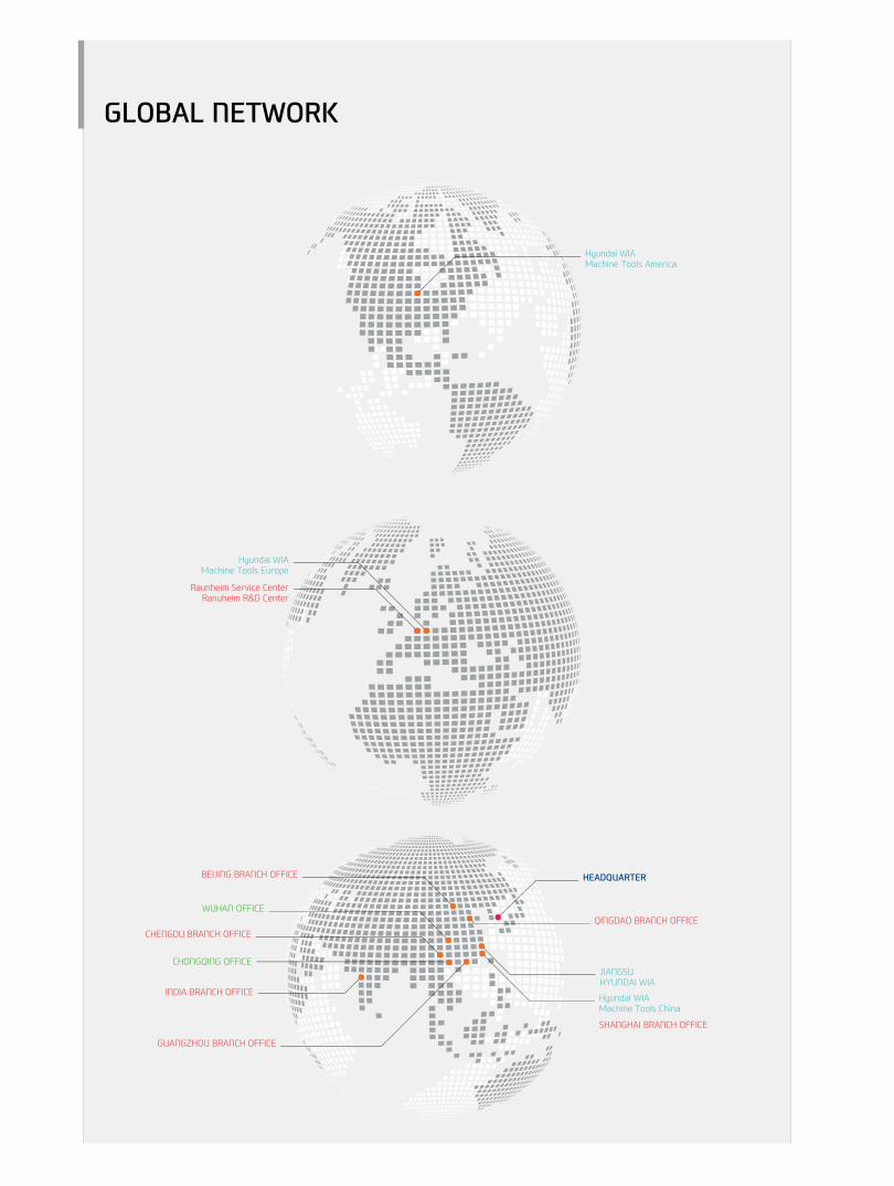
GLOBAL NETWORK

32+
33
E2
00 S
ERIE
SC
nC
Tu
rn
ing
Cen
Ter
HYu
nD
Ai W
iAM
ACH
ine
TOO
L
OVERSEAS OFFICES
GLOBAL NETWORK
Changwon Technical Center / R&D Center / Factory153, Jeongdong-ro, Seongsan-gu, Changwon-si, Gyeongsangnam-do, Korea (Zip Code : 51533)TEL : +82 55 280 9114 FAX : +82 55 282 9680
Uiwang Technical Center / R&D Center37, Cheoldobangmulgwan-ro, Uiwang-si, Gyeonggi-do, Korea (Zip Code : 16082)TEL : +82 31 596 8209 Fax : +82 55 210 9804
HEADqUARTER
HYUNDAI WIAMachine Tools America 265, Spring Lake Drive, Itasca, IL, 60143
TEL : +1 630 625 5600 FAX : +1 630 625 4733
Jiangsu HYUNDAI WIACompany No.6 Fenghuang Road, Fenghuang Town, Zhangjjagang City, Jiangsu province, China
TEL : +86 512 5672 6808FAX : +86 512 5671 6960
Chengdu Branch OfficeNO.508 Room, B Block, AFC Plaza, NO.88 Jiaozi Road, High-tech Zone, Chengdu, China
TEL : +86 028 8665 2985FAX : +86 028 8665 2985
HYUNDAI WIAMachine Tools Europe Kaiserleipromenade 5, 63067 Offenbach, Germany
TEL : +49 69271 472 701FAX : +49 69271 472 719
Hyundai WIA Machine Tools ChinaShanghai Branch Office1-3F, Bldg6, No.1535 Hongmei Road, Xuhui District, Shanghai, China
TEL : +86 021 6427 9885FAX : +86 021 6427 9890
qingdao Branch OfficeRoom 1207, Cai Fu Building, 182-6 Haier Middle Road, Qingdao, China
TEL : +86 532 8667 9334FAX : +86 532 8667 9338
Raunheim Service CenterRaunheim R&D CenterFrankfurter. 63, 65479 Raunheim, Germany
TEL : +49 6142 9256 111 FAX : +49 6142 9256 100
Beijing Branch OfficeFloor 14, Zhonghangji Plaza B, No.15 Ronghua South Road, BDA Dist., Daxing Dist., Beijing, China 100176
TEL : +86 010 8453 9850FAX : +86 010 8453 9853
Wuhan Office306-2, A Tower,Jiayu Gpmggian, No12 Chuangye Road, Economic Development Zone, Wuhan, Hubei, China
TEL : +86 027 5952 3256FAX : +86 027 5952 3256
Inida Branch Office#4/169, Rajiv Gandhi Salai, (OMR), Kandanchavadi, Chennai-600 096, Tamilnadu, IndiaTEL: +91-44-3290-1719
Guangzhou Branch OfficeRoom 311, Unit 1-3, POLY TAL TU WUN, Hanxi Avenue, Panyu District, Guangzhou, China
TEL : +86 020 8550 6595 FAX : +86 020 8550 6597
Chongqing OfficeRoom 951, #3, Jinrongcheng T3, Jiangbei, Chongqing, China
TEL : +86 23 6701 2970
E200C MovieE200A Movie
Head Office & Factory153, Jeongdong-ro, Seongsan-gu, Changwon-si, Gyeongsangnam-do Tel +82 55 280 9500
Overseas Sales Team16F, 37, Cheoldobangmulgwan-ro, Uiwang-si, Gyeonggi-do Tel +82 31 593 8173
HYUNDAI WIA Machine Tools America265 Spring Lake Drive,Itasca, IL, 60143 Tel +1 (630) 625 5600 Fax +1 (630) 625 4733
HYUNDAI WIA Machine Tools EuropeKaiserleipromenade 5, D-63067 Offenbach, Germany Tel +49 69271 472 701 Fax +49 69271 472 719
Inida Branch Office#4/169, Rajiv Gandhi Salai, (OMR), Kandanchavadi, Chennai-600 096, Tamilnadu, India Tel +91 44 3290 1719
http://machine.hyundai-wia.com
2016-11 003.002 ENG