E1100/ Terminal Blocks - Crompton...
50
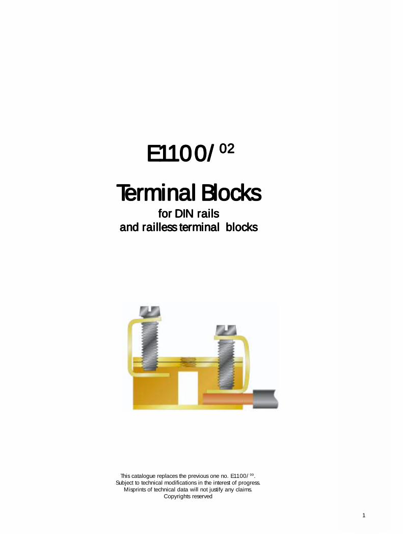
E E E E E1 1 11 1 10 0 00/ 0/ 0/ 0/ 0/ 02 02 02 02 02 T T Ter er er er erminal Blocks minal Blocks minal Blocks minal Blocks minal Blocks for DIN rails for DIN rails for DIN rails for DIN rails for DIN rails and railless terminal blocks and railless terminal blocks and railless terminal blocks and railless terminal blocks and railless terminal blocks This catalogue replaces the previous one no. E1100/ 99 . Subject to technical modifications in the interest of progress. Misprints of technical data will not justify any claims. Copyrights reserved 1
Transcript of E1100/ Terminal Blocks - Crompton...
1
E E E E E1111111111000000/0/0/0/0/0202020202
TTTTTerererererminal Blocksminal Blocksminal Blocksminal Blocksminal Blocksfor DIN railsfor DIN railsfor DIN railsfor DIN railsfor DIN rails
and railless terminal blocksand railless terminal blocksand railless terminal blocksand railless terminal blocksand railless terminal blocks
This catalogue replaces the previous one no. E1100/99.Subject to technical modifications in the interest of progress.
Misprints of technical data will not justify any claims.Copyrights reserved
1
2
4
16-19
8-11
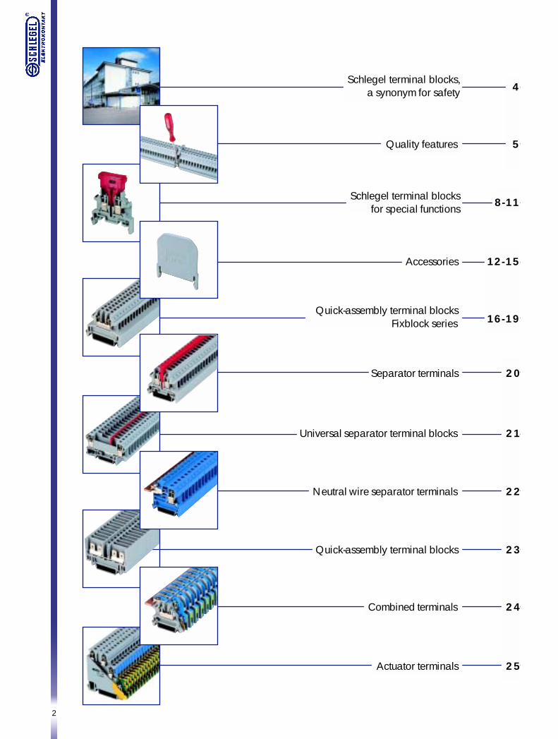
Schlegel terminal blocks,a synonym for safety
Quality features 5
Schlegel terminal blocksfor special functions
Quick-assembly terminal blocksFixblock series
Separator terminals 20
Universal separator terminal blocks 21
Neutral wire separator terminals 22
Quick-assembly terminal blocks 23
Combined terminals 24
Actuator terminals 25
Accessories 12-15
3
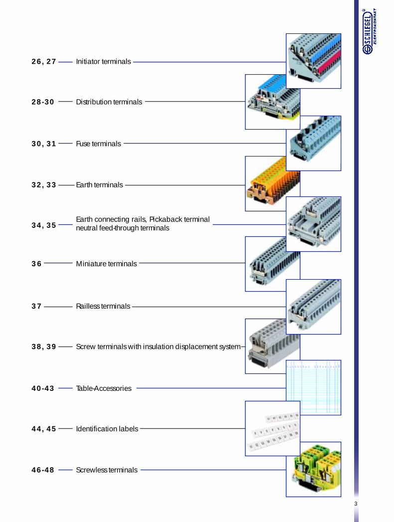
26, 27 Initiator terminals
28-30 Distribution terminals
30, 31 Fuse terminals
34, 35Earth connecting rails, Pickaback terminalneutral feed-through terminals
36 Miniature terminals
37 Railless terminals
38, 39 Screw terminals with insulation displacement system
40-43 Table-Accessories
44, 45 Identification labels
46-48 Screwless terminals
32, 33 Earth terminals
4
Schlegel terminal blocksa synonym for safety
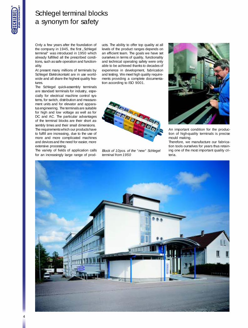
Only a few years after the foundation ofthe company in 1945, the first „Schlegelterminal“ was introduced in 1950 whichalready fulfilled all the prescribed condi-tions, such as safe operation and function-ality.At present many millions of terminals bySchlegel Elektrokontakt are in use world-wide and all share the highest quality fea-tures.The Schlegel quick-assembly terminalsare standard terminals for industry, espe-cially for electrical machine control sys-tems, for switch, distribution and measure-ment units and for elevator and appara-tus engineering. The terminals are suitablefor high and low voltage as well as forDC and AC. The particular advantagesof the terminal blocks are their short as-sembly times and their small dimensions.The requirements which our products haveto fulfill are increasing, due to the use ofmore and more complicated machinesand devices and the need for easier, moreextensive processing.The variety of fields of application callsfor an increasingly large range of prod-
ucts. The ability to offer top quality at alllevels of the product ranges depends onan efficient team. The goals we have setourselves in terms of quality, functionalityand technical operating safety were onlyable to be achieved thanks to decades ofexperience in development, fabricationand testing. We meet high quality require-ments providing a complete documenta-tion according to ISO 9001.
Block of 10pcs. of the “new“ Schlegelterminal from 1950
An important condition for the produc-tion of high-quality terminals is precisemould making.Therefore, we manufacture our fabrica-tion tools ourselves for years thus retain-ing one of the most important quality cri-teria.
5
Schlegel terminal blocksQuality features
Insulating materialsfor terminal casings
Creepage path and air path
The casings of our terminal blocks aremade of high-quality polyamide. Nationaland international regulations prescribewith utmost precision which characteristicsthe plastic must have.
The adherence to these regulations is aconstituent part of the quality assurancesystem according to DIN ISO 9001 whichour company has introduced. In addition,the relevant authorities must approve thematerials. Regular manufacturing controls
made by the certification authoritiesmonitor their exclusive application.
Due to the variety of certifications whichour terminal blocks have obtainedworldwide, only the best material issuitable for the sum of all requirements.Consequently, the approval marks on theterminals ensure the application of rawmaterials of the highest quality only.
The creepage path is the path betweentwo live parts with different potentialsalong the insulating material surface.The air path is the thread dimensionbetween two live parts with differentpotentials.Since normally the creepage path mustbe longer than the air path, the creepagepath is lenghtened by means of ribs orchases.National and international regulationsprescribe how long creepage and airpaths must be. Their lengths depend onthe voltage between the live parts, the
degree of soiling and the excess-voltageclass.With regard to the creepage path, thenature of the insulating material is alsotaken into consideration.The higher the quality of the insulant, thesmaller the creepage distance can be.Since shorter creepage paths allow smallersizes, high-quality plastics provideadvantages with regard to the externaldimensions of a product.
Connecting cross section The rated connecting capacity isindicated on the back wall of the terminalblocks. This is the cross section which theterminal block in single, multiple and finecore design can accommodate. All thedata and tests such as electric loading,heating and mechanical safety refer tothis. These tests are not only carried out inour firm but are part of the type-testscarried out by the testing bodies in orderto obtain national certification. This isdocumented by the permission to displaythe marks on the terminal blocks.The terminal blocks must allow the con-ductors to be connected without parti-cular preparing. Straightening single andmultiple conductors as well as twistingfine-core conductors do not count asspecial.Soldering of fine-core conductors is notallowed, because the soldering-tin tendsto creep.When using wire end ferrules, theconnectable cross section may be reducedby one level. This and other factors makethem unnecessary for SCHLEGEL terminalblocks.
Up to a cross section of 35 mm² theterminal blocks must also be able toclamp the two next smaller cross sections.In the case of SCHLEGEL terminal blocks,the nominal cross sections are graduatedin a manner that all the existing crosssections from 0.5 to 240 mm² are fullycovered.It must be stressed that SCHLEGELterminals up to a nominal cross section of4 mm² also clamp conductors down to adiameter of 0.2 mm².In the U.S. and the Anglo-Saxon countriesthe AWG number is used as a crosssection indication. The AWG cross sectionindication is to be found on the terminalblock if it is accordingly certified.
Protection against accidental In accordance with VBG 4 (UVV)protection against accidental contact isrequired for every electrical device.According to the arrangement of the units,this protection must meet with certainrequirements , whereby a distinction ismade between protection of the fingersand protection of the back of the hands.
contactcontactcontactcontactcontact
6
This is tested by making an artificial metalfinger with movable finger joints. The fin-ger is connected to an indicator lampand used to test whether parts under volt-age can be touched.Safety from finger-touch is required withina planar circle measuring 60 mm in di-ameter which is imagined around an “oc-
This is required within a planar circlemeasuring 100 mm in diameter aroundoperating elements as described above.Safety is tested with a ball measuring 50mm in diameter in place of the test fin-ger. When carr ying out both tests, it
casionally manipulated” operating ele-ment, e.g. the reset button of a motorprotective relay, the setting button of atime-delay relay, a fuse, etc.
should be noted that the test finger is notpermitted to grip the entire periphery ofa cover. It is therefore suf ficient to use acover which only prevents contact fromthe front.
Safety from finger-touch
Safety from touch by theback of the hand
Metal parts
Types of connectionScrewed connections
The metal parts of the quick-assemblyterminals are made of a high-strengthcopper alloy ideally suited for electricalconnections. They are nickel electro-plated, and in some cases also tin-plated,in order to guarantee a high resistanceto corrosion.
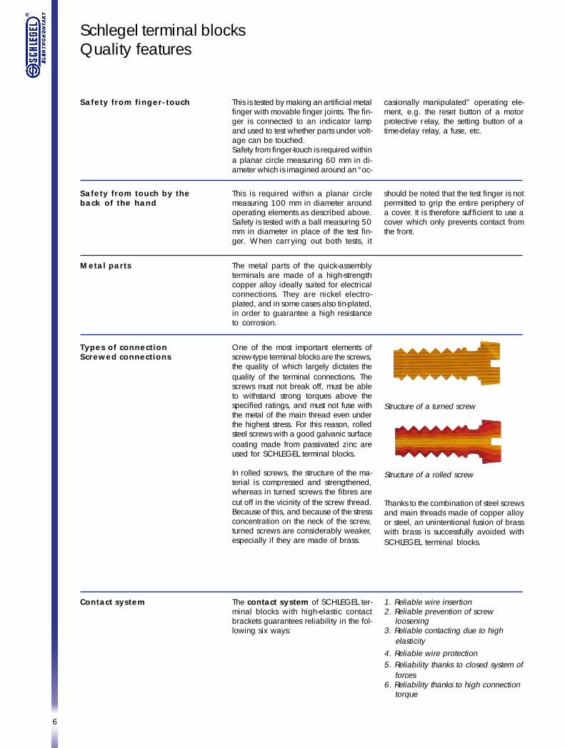
One of the most important elements ofscrew-type terminal blocks are the screws,the quality of which largely dictates thequality of the terminal connections. Thescrews must not break off, must be ableto withstand strong torques above thespecified ratings, and must not fuse withthe metal of the main thread even underthe highest stress. For this reason, rolledsteel screws with a good galvanic surfacecoating made from passivated zinc areused for SCHLEGEL terminal blocks.
In rolled screws, the structure of the ma-terial is compressed and strengthened,whereas in turned screws the fibres arecut off in the vicinity of the screw thread.Because of this, and because of the stressconcentration on the neck of the screw,turned screws are considerably weaker,especially if they are made of brass.
Structure of a turned screw
Structure of a rolled screw
Thanks to the combination of steel screwsand main threads made of copper alloyor steel, an unintentional fusion of brasswith brass is successfully avoided withSCHLEGEL terminal blocks.
The contact system of SCHLEGEL ter-minal blocks with high-elastic contactbrackets guarantees reliability in the fol-lowing six ways:
1. Reliable wire insertion2. Reliable prevention of screw loosening3. Reliable contacting due to high elasticity4. Reliable wire protection5. Reliability thanks to closed system of forces6. Reliability thanks to high connection torque
Contact system
Schlegel terminal blocksQuality features
7
Flat-plug connectionsFlat-plug connectionsFlat-plug connectionsFlat-plug connectionsFlat-plug connections Terminals with flat-plug connections aresuitable for flat-plug sockets complyingwith the German Standard DIN 46247.
Soldering connectionsSoldering connectionsSoldering connectionsSoldering connectionsSoldering connections Tin electroplating on a nickel diffusionbarrier layer ensures excellent solderingcharacteristics.
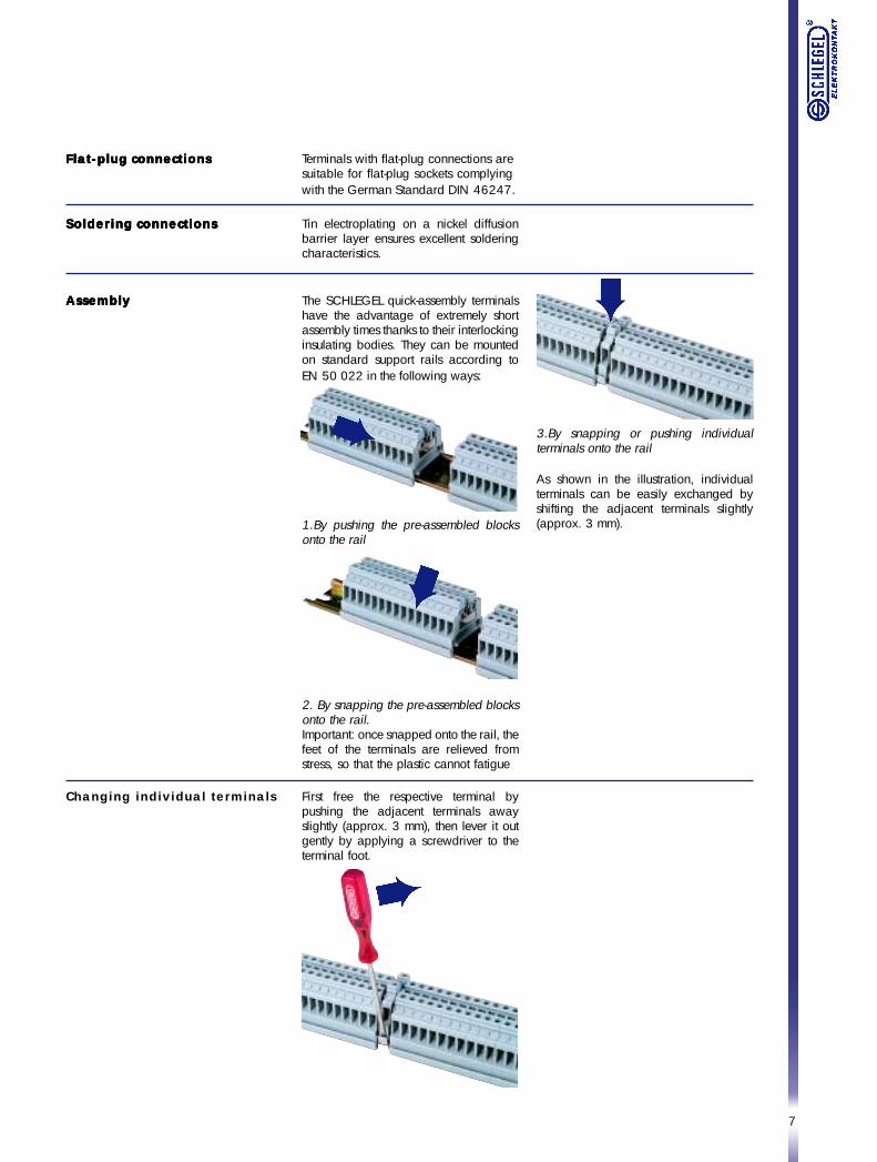
AssemblyAssemblyAssemblyAssemblyAssembly The SCHLEGEL quick-assembly terminalshave the advantage of extremely shortassembly times thanks to their interlockinginsulating bodies. They can be mountedon standard support rails according toEN 50 022 in the following ways:
1.By pushing the pre-assembled blocksonto the rail
2. By snapping the pre-assembled blocksonto the rail.Important: once snapped onto the rail, thefeet of the terminals are relieved fromstress, so that the plastic cannot fatigue
3.By snapping or pushing individualterminals onto the rail
As shown in the illustration, individualterminals can be easily exchanged byshifting the adjacent terminals slightly(approx. 3 mm).
Changing individual terminals First free the respective terminal bypushing the adjacent terminals awayslightly (approx. 3 mm), then lever it outgently by applying a screwdriver to theterminal foot.
8
Schlegel terminalsfor special functions
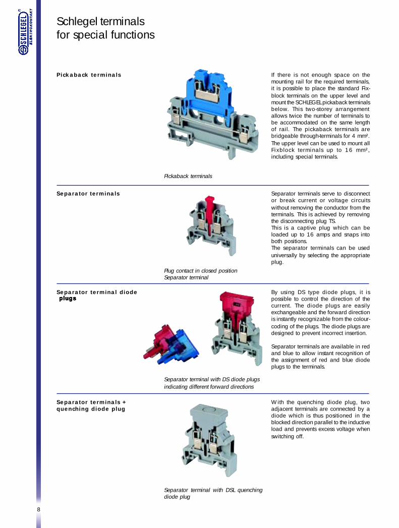
Plug contact in closed positionSeparator terminal
Pickaback terminals
Separator terminals
Separator terminal diode
Separator terminal with DS diode plugsindicating different forward directions
Separator terminals +quenching diode plug
If there is not enough space on themounting rail for the required terminals,it is possible to place the standard Fix-block terminals on the upper level andmount the SCHLEGEL pickaback terminalsbelow. This two-storey arrangementallows twice the number of terminals tobe accommodated on the same lengthof rail. The pickaback terminals arebridgeable through-terminals for 4 mm².The upper level can be used to mount allFixblock terminals up to 16 mm²,including special terminals.
Pickaback terminals
Separator terminals serve to disconnector break current or voltage circuitswithout removing the conductor from theterminals. This is achieved by removingthe disconnecting plug TS.This is a captive plug which can beloaded up to 16 amps and snaps intoboth positions.The separator terminals can be useduniversally by selecting the appropriateplug.
By using DS type diode plugs, it ispossible to control the direction of thecurrent. The diode plugs are easilyexchangeable and the forward directionis instantly recognizable from the colour-coding of the plugs. The diode plugs aredesigned to prevent incorrect insertion.
Separator terminals are available in redand blue to allow instant recognition ofthe assignment of red and blue diodeplugs to the terminals.
With the quenching diode plug, twoadjacent terminals are connected by adiode which is thus positioned in theblocked direction parallel to the inductiveload and prevents excess voltage whenswitching off.
Separator terminal with DSL quenchingdiode plug
plugsplugsplugsplugsplugs
9
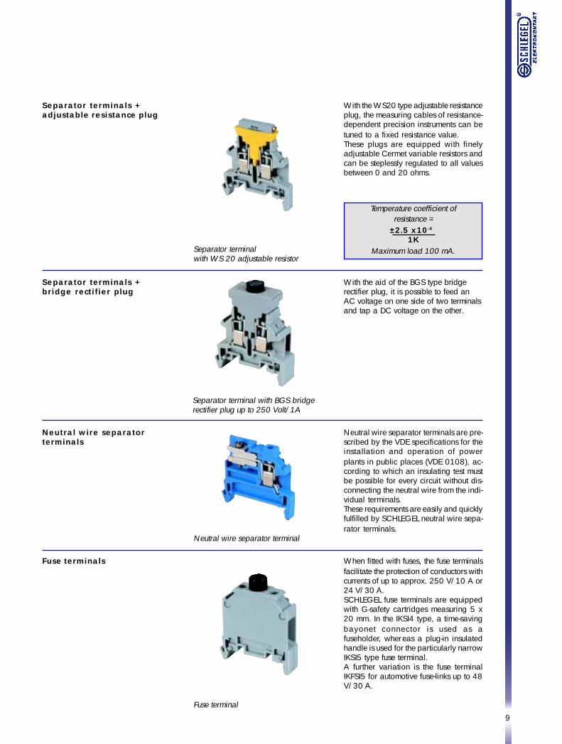
Separator terminals +adjustable resistance plug
Separator terminalwith WS 20 adjustable resistor
Temperature coefficient ofresistance =
±2.5 x10⁻⁴
1KMaximum load 100 mA.
Neutral wire separatorterminals
Separator terminals +bridge rectifier plug
Separator terminal with BGS bridgerectifier plug up to 250 Volt/1A
With the WS20 type adjustable resistanceplug, the measuring cables of resistance-dependent precision instruments can betuned to a fixed resistance value.These plugs are equipped with finelyadjustable Cermet variable resistors andcan be steplessly regulated to all valuesbetween 0 and 20 ohms.
With the aid of the BGS type bridgerectifier plug, it is possible to feed anAC voltage on one side of two terminalsand tap a DC voltage on the other.
Neutral wire separator terminals are pre-scribed by the VDE specifications for theinstallation and operation of powerplants in public places (VDE 0108), ac-cording to which an insulating test mustbe possible for every circuit without dis-connecting the neutral wire from the indi-vidual terminals.These requirements are easily and quicklyfulfilled by SCHLEGEL neutral wire sepa-rator terminals.
Neutral wire separator terminal
Fuse terminals When fitted with fuses, the fuse terminalsfacilitate the protection of conductors withcurrents of up to approx. 250 V/10 A or24 V/30 A.SCHLEGEL fuse terminals are equippedwith G-safety cartridges measuring 5 x20 mm. In the IKSI4 type, a time-savingbayonet connector is used as afuseholder, whereas a plug-in insulatedhandle is used for the particularly narrowIKSI5 type fuse terminal.A further variation is the fuse terminalIKFSI5 for automotive fuse-links up to 48V/30 A.
Fuse terminal
10
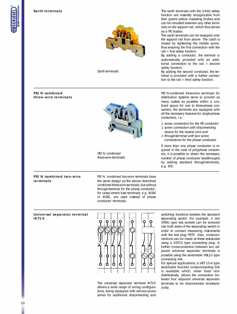
Earth terminals The earth terminals with the 3-fold safetyfunction are instantly recognizable fromtheir green/yellow insulating bodies andcan be mounted between any other termi-nals on the support rail, which thus servesas a PE busbar.The earth terminals can be snapped ontothe support rail from above. The catch isclosed by tightening the middle screw,thus ensuring the first connection with therail = first safety function.By adding a conductor, the terminal isautomatically provided wiht an addi-tional connection to the rail = secondsafety function.By adding the second conductor, the ter-minal is provided with a further connec-tion to the rail = third safety function.
Earth terminals
PE/N-combined three-wire terminals fordistribution systems serve to provide asmany outlets as possible within a con-fined space for one to three-phase con-sumers. the terminals are equipped withall the necessary features for single-phaseconsumers, i.e.
1 screw connection for the PE conductor1 screw connection with disconnecting
device for the neutral wire and1 through-terminal with two screw
connections for the phase conductor
If more than one phase conductor is re-quired in the case of polyphase consum-ers, it is possible to obtain the necessarynumber of phase conductor leadthroughsby adding standard through-terminals,e.g. IK5.
PE/N combinedthree-wire terminals
PE/N combined two-wire terminals havethe same design as the above describedcombined three-wire terminals, but withoutthrough-terminal for the phase conductor,for cases where fuse terminals, e.g. IKSI4or IKSI5, are used instead of phaseconductor terminals.
PE/N combinedthree-wire terminals
PE/N combined two-wireterminals
Universal separator terminalIKT10
The universal separator terminal IKT10allows a wide range of wiring configura-tions, being equipped with various acces-sories for additional disconnecting and
switching functions besides the standardseparating switch. For example, 4 mmSTB4L type test sockets can be screwedinto both sides of the separating switch inorder to connect measuring instrumentswith the test plug PST4. Also, cross-con-nections can be made at these test-socketusing a VST10 type connecting plug. Afurther cross-connection between two ad-jacent universal separator terminals ispossible using the switchable VBL10 typeconnecting link.For special applications, a VBT 10-4 typeswitchable four-fold cross-connecting linkis available which, when fixed non-distributively, allows the connection be-tween four adjacent universal separatorterminals to be disconnected simultane-ously.
11
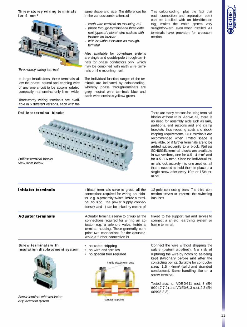
Three-storey wiring terminalsfor 4 mm2
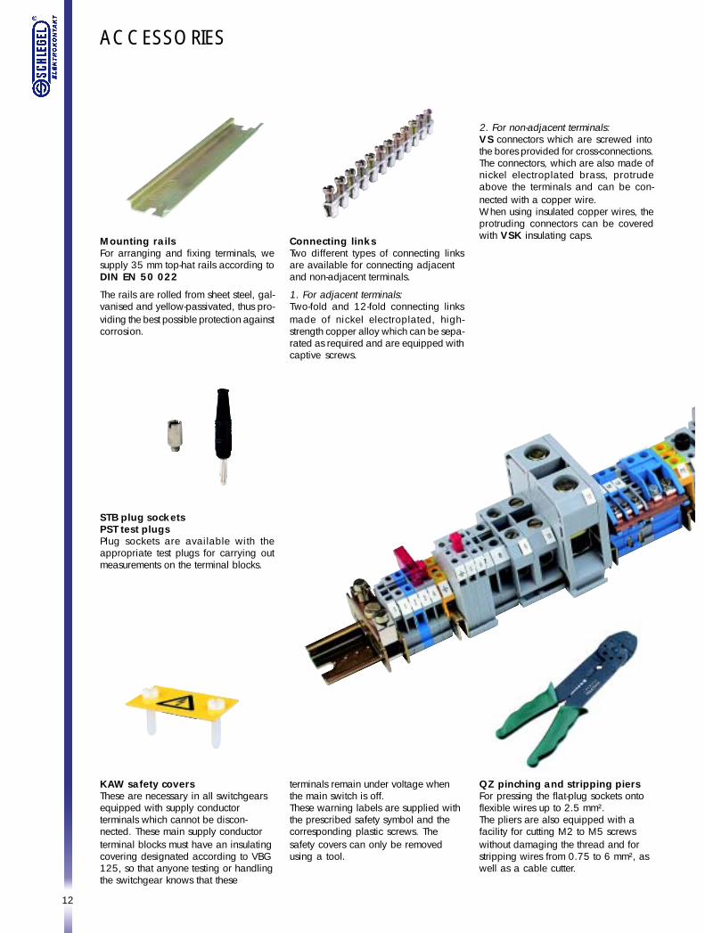
Railless terminal blocks
In large installations, these terminals al-low the phase, neutral and earthing wireof any one circuit to be accommodatedcompactly in a terminal only 6 mm wide.
Three-storey wiring terminals are avail-able in 6 different versions, each with the
There are many reasons for using terminalblocks without rails. Above all, there isno need for assembly aids such as rails,partitions, end sections and end clampbrackets, thus reducing costs and stock-keeping requirements. Our terminals arerecommended when limited space isavailable, or if further terminals are to beadded subsequently to a block. RaillessSCHLEGEL terminal blocks are availablein two versions, one for 0.5 - 4 mm2 andfor 0.5 - 16 mm2. Since the individual ter-minals lock securely into one another, allthat is needed to hold them in place is asingle screw after every 10th or 15th ter-minal.
Railless terminal blocksview from below
Initiator terminalsInitiator terminalsInitiator terminalsInitiator terminalsInitiator terminals Initiator terminals serve to group all theconnections required for wiring an initia-tor, e.g. a proximity switch, inside a termi-nal housing. The power supply connec-tions (+ and –) can be linked by means of
same shape and size. The differences liein the various combinations of
- earth wire terminal on mounting rail- phase through-terminal and three diffe
rent types of netural wire sockets withisolator on busbar
- with or without isolator as through-terminal
Also available for polyphase systemsare single and double-pole through-termi-nals for phase conductors only, whichmay be combined with earth wire termi-nals on the mounting rail.
The individual function ranges of the ter-minals are indicated by colour-coding,whereby phase through-terminals aregrey, neutral wire terminals blue andearth wire terminals yellow/green.
This colour-coding, plus the fact thateach connection and separation pointcan be labelled with an identificationtag, makes the entire system verystraightforward, even when installed. Allterminals have provision for cross-con-nection.
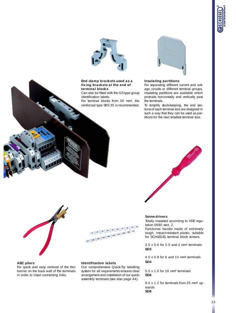
Screw terminals withinsulation displacement system
• no cable stripping• no wire end ferrules• no special tool required
Connect the wire without stripping thecable (patent applied). No risk ofrupturing the wire by notching as beingkept stationary before and after thecontacting points. Suitable for conductorsizes 1.5 - 4mm² (solid and strandedconductors). Same handling like on ascrew terminal.
Tested acc. to: VDE 0611 sect. 3 (EN60947-7-2) and VDE 0613 sect. 2-3 (EN60998-2-3).
Screw terminal with insulationdisplacement system
12-pole connecting bars. The third con-nection serves to transmit the switchingimpulses.
Actuator terminalsActuator terminalsActuator terminalsActuator terminalsActuator terminals Actuator terminals serve to group all theconnections required for wiring an ac-tuator, e.g. a solenoid valve, inside aterminal housing. These generally com-prise two connections for the actuator,while a further connection is
linked to the support rail and serves toconnect a shield, earthing system orframe terminal.
highly elastic elements
contacting points
Three-storey wiring terminal
12
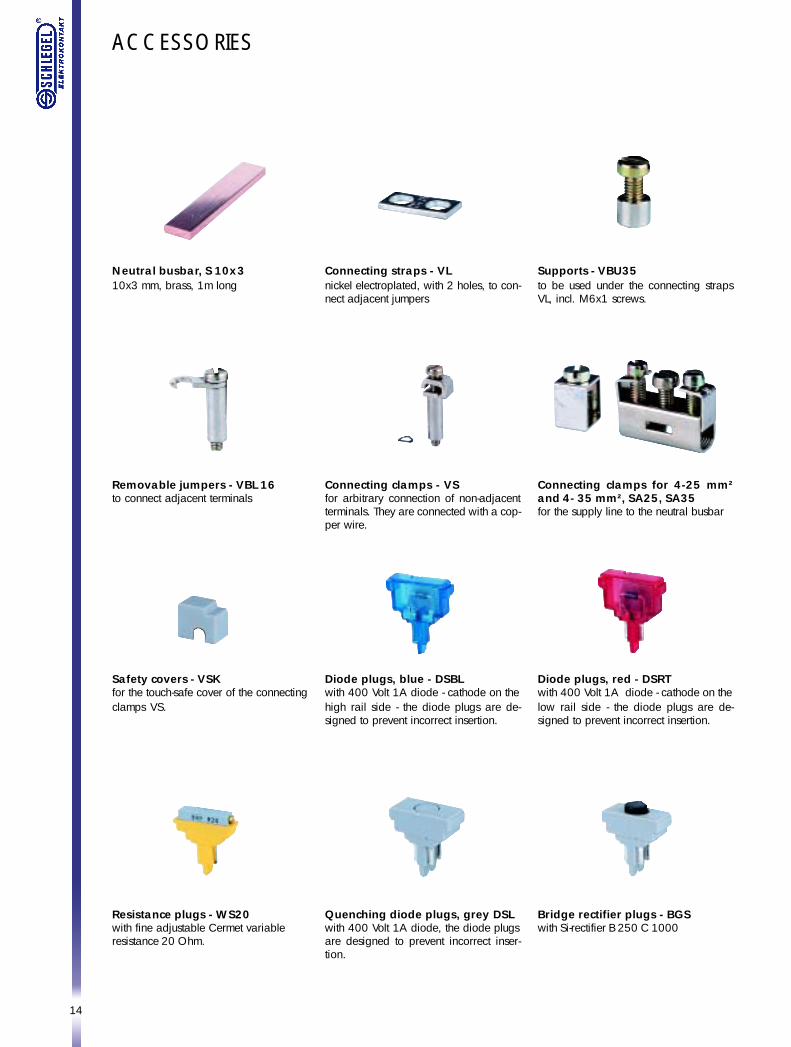
QZ pinching and stripping piersFor pressing the flat-plug sockets ontoflexible wires up to 2.5 mm².The pliers are also equipped with afacility for cutting M2 to M5 screwswithout damaging the thread and forstripping wires from 0.75 to 6 mm², aswell as a cable cutter.
ACCESSORIES
Mounting railsFor arranging and fixing terminals, wesupply 35 mm top-hat rails according toDIN EN 50 022
The rails are rolled from sheet steel, gal-vanised and yellow-passivated, thus pro-viding the best possible protection againstcorrosion.
Connecting linksTwo different types of connecting linksare available for connecting adjacentand non-adjacent terminals.
1. For adjacent terminals:Two-fold and 12-fold connecting linksmade of nickel electroplated, high-strength copper alloy which can be sepa-rated as required and are equipped withcaptive screws.
KAW safety coversThese are necessary in all switchgearsequipped with supply conductorterminals which cannot be discon-nected. These main supply conductorterminal blocks must have an insulatingcovering designated according to VBG125, so that anyone testing or handlingthe switchgear knows that these
STB plug socketsPST test plugsPlug sockets are available with theappropriate test plugs for carrying outmeasurements on the terminal blocks.
2. For non-adjacent terminals:VS connectors which are screwed intothe bores provided for cross-connections.The connectors, which are also made ofnickel electroplated brass, protrudeabove the terminals and can be con-nected with a copper wire.When using insulated copper wires, theprotruding connectors can be coveredwith VSK insulating caps.
terminals remain under voltage whenthe main switch is off.These warning labels are supplied withthe prescribed safety symbol and thecorresponding plastic screws. Thesafety covers can only be removedusing a tool.
13
ScrewdriversTotally insulated according to VDE regu-lation 0680 sect. 2.Functional handle made of extremelytough, impact-resistant plastic, suitablefor SCHLEGEL terminal block screws.
3.5 x 0.6 for 2.5 and 4 mm² terminalsSD3
4.0 x 0.8 for 6 and 10 mm² terminalsSD4
5.5 x 1.0 for 16 mm² terminalsSD6
8.0 x 1.2 for terminals from 25 mm² up-wardsSD8
Insulating partitionsFor separating different current and volt-age circuits or different terminal groups,insulating partitions are available whichprotrude horizontally and vertically pastthe terminals.To simplify stock-keeping, the end sec-tions of each terminal size are designed insuch a way that they can be used as par-titions for the next smallest terminal size.
End clamp brackets used as afixing brackets at the end ofterminal blocksCan also be fitted with the GS type groupidentification labels.For terminal blocks from 50 mm2, thereinforced type SKS 35 is recommended.
Identification labelsOur comprehensive Quick-Tip labellingsystem for all requirements ensures cleararrangement and installation of our quick-assembly terminals (see also page 44).
ABZ pliersFor quick and easy removal of the thinbarrier on the back wall of the terminalsin order to insert connecting links.
14
Neutral busbar, S 10x310x3 mm, brass, 1m long
ACCESSORIES
Connecting straps - VLnickel electroplated, with 2 holes, to con-nect adjacent jumpers
Supports - VBU35to be used under the connecting strapsVL, incl. M6x1 screws.
Removable jumpers - VBL 16to connect adjacent terminals
Connecting clamps - VSfor arbitrary connection of non-adjacentterminals. They are connected with a cop-per wire.
Connecting clamps for 4-25 mm²and 4- 35 mm², SA25, SA35for the supply line to the neutral busbar
Safety covers - VSKfor the touch-safe cover of the connectingclamps VS.
Diode plugs, blue - DSBLwith 400 Volt 1A diode - cathode on thehigh rail side - the diode plugs are de-signed to prevent incorrect insertion.
Diode plugs, red - DSRTwith 400 Volt 1A diode - cathode on thelow rail side - the diode plugs are de-signed to prevent incorrect insertion.
Resistance plugs - WS20with fine adjustable Cermet variableresistance 20 Ohm.
Quenching diode plugs, grey DSLwith 400 Volt 1A diode, the diode plugsare designed to prevent incorrect inser-tion.
Bridge rectifier plugs - BGSwith Si-rectifier B 250 C 1000
15
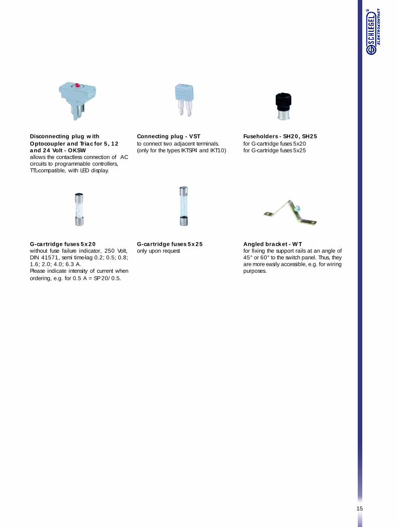
Disconnecting plug withOptocoupler and Triac for 5, 12and 24 Volt - OKSWallows the contactless connection of ACcircuits to programmable controllers,TTL-compatible, with LED display.
Connecting plug - VSTto connect two adjacent terminals.(only for the types IKTSP4 and IKT10)
Fuseholders - SH20, SH25for G-cartridge fuses 5x20for G-cartridge fuses 5x25
G-cartridge fuses 5x20without fuse failure indicator, 250 Volt,DIN 41571, semi time-lag 0.2; 0.5; 0.8;1.6; 2.0; 4.0; 6.3 A.Please indicate intensity of current whenordering, e.g. for 0.5 A = SP 20/0.5.
Angled bracket - WTfor fixing the support rails at an angle of45° or 60° to the switch panel. Thus, theyare more easily accessible, e.g. for wiringpurposes.
G-cartridge fuses 5x25only upon request
16
Type
Terminal thickness
DIN rail
Connection type
Conductor sizes
Rated cross section
Voltage
Current rating acc. to VDE 0611/UL/CSA
Tightening torque VDE 0611 / UL486E
Insulating material
Accessories
Top hat rail 35 x 7.5 mm
Jumper
Connecting strap
Support
Removable jumper
Connecting clamp
Insulating cap
Test socket
Test plug
Insulating end section
Insulating partition
Safety cover
End clamp bracketreinforced version
Identification labels, strips of ten
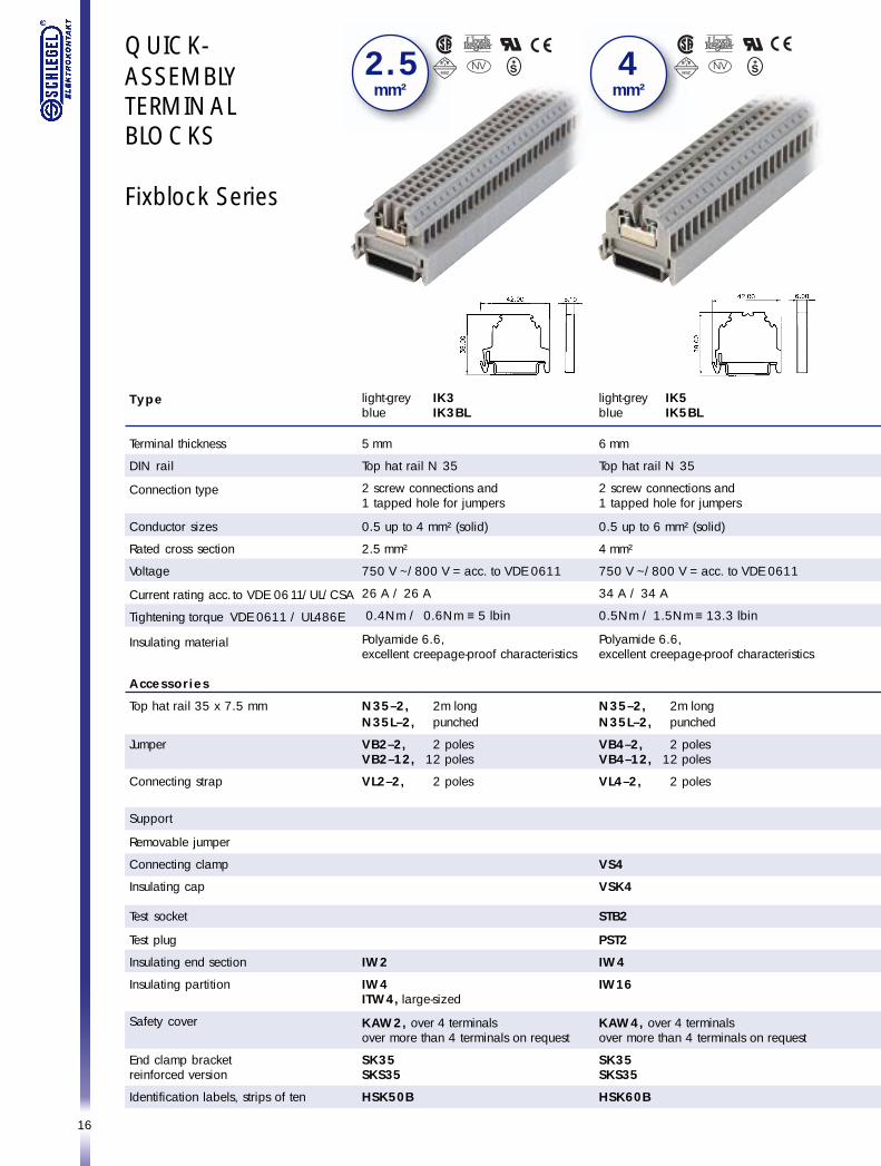
QUICK-ASSEMBLYTERMINALBLOCKS
Fixblock Series
light-grey IK3blue IK3BL
5 mm
Top hat rail N 35
2 screw connections and1 tapped hole for jumpers
0.5 up to 4 mm² (solid)
2.5 mm²
750 V ~/800 V = acc. to VDE 0611
26 A / 26 A
0.4Nm / 0.6Nm ≡ 5 lbin
Polyamide 6.6,excellent creepage-proof characteristics
N35–2, 2m longN35L–2, punched
VB2–2, 2 polesVB2–12, 12 poles
VL2–2, 2 poles
IW2
IW4ITW4, large-sized
KAW2, over 4 terminalsover more than 4 terminals on request
SK35SKS35
HSK50B
2 . 5mm²
light-grey IK5blue IK5BL
6 mm
Top hat rail N 35
2 screw connections and1 tapped hole for jumpers
0.5 up to 6 mm² (solid)
4 mm²
750 V ~/800 V = acc. to VDE 0611
34 A / 34 A
0.5Nm / 1.5Nm ≡ 13.3 lbin
Polyamide 6.6,excellent creepage-proof characteristics
N35–2, 2m longN35L–2, punched
VB4–2, 2 polesVB4–12, 12 poles
VL4–2, 2 poles
VS4
VSK4
STB2
PST2
IW4
IW16
KAW4, over 4 terminalsover more than 4 terminals on request
SK35SKS35
HSK60B
4mm²
17
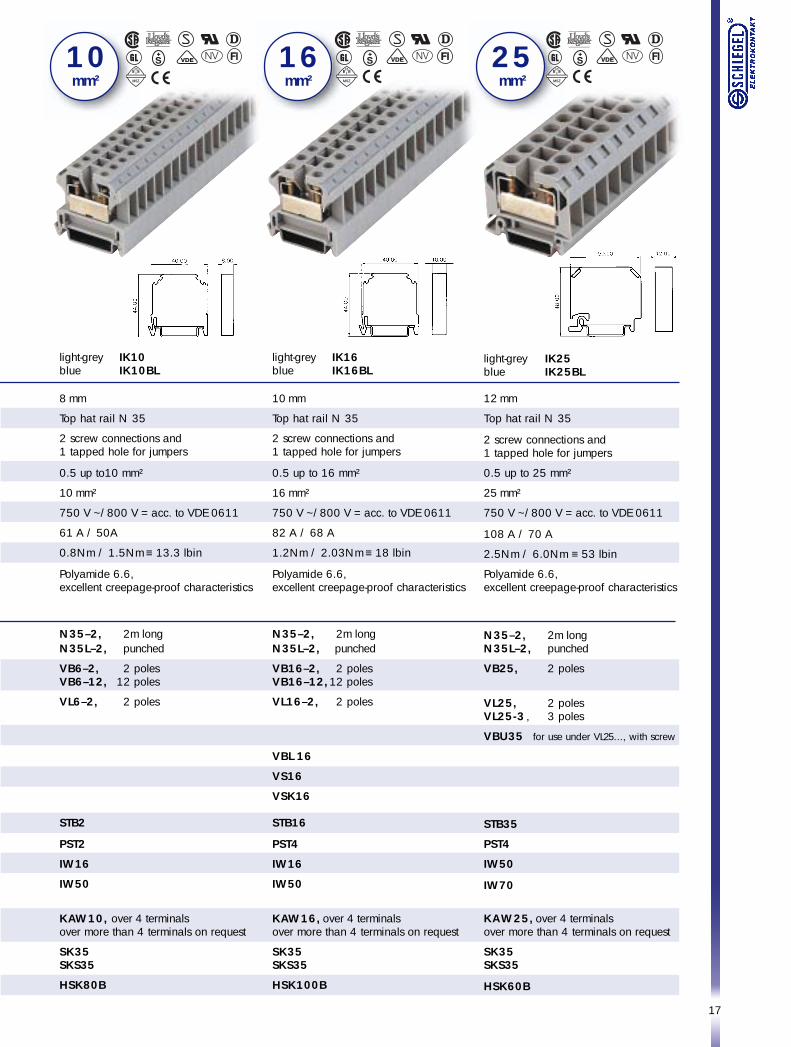
light-grey IK10blue IK10BL
8 mm
Top hat rail N 35
2 screw connections and1 tapped hole for jumpers
0.5 up to10 mm²
10 mm²
750 V ~/800 V = acc. to VDE 0611
61 A / 50A
0.8Nm / 1.5Nm ≡ 13.3 lbin
Polyamide 6.6,excellent creepage-proof characteristics
N35–2, 2m longN35L–2, punched
VB6–2, 2 polesVB6–12, 12 poles
VL6–2, 2 poles
STB2
PST2
IW16
IW50
KAW10, over 4 terminalsover more than 4 terminals on request
SK35SKS35
HSK80B
1 0 mm²
light-grey IK16blue IK16BL
10 mm
Top hat rail N 35
2 screw connections and1 tapped hole for jumpers
0.5 up to 16 mm²
16 mm²
750 V ~/800 V = acc. to VDE 0611
82 A / 68 A
1.2Nm / 2.03Nm ≡ 18 lbin
Polyamide 6.6,excellent creepage-proof characteristics
N35–2, 2m longN35L–2, punched
VB16–2, 2 polesVB16–12,12 poles
VL16–2, 2 poles
VBL 16
VS16
VSK16
STB16
PST4
IW16
IW50
KAW16, over 4 terminalsover more than 4 terminals on request
SK35SKS35
HSK100B
1 6 mm²
light-grey IK25blue IK25BL
12 mm
Top hat rail N 35
2 screw connections and1 tapped hole for jumpers
0.5 up to 25 mm²
25 mm²
750 V ~/800 V = acc. to VDE 0611
108 A / 70 A
2.5Nm / 6.0Nm ≡ 53 lbin
Polyamide 6.6,excellent creepage-proof characteristics
N35–2, 2m longN35L–2, punched
VB25, 2 poles
VL25, 2 polesVL25-3 , 3 poles
VBU35 for use under VL25..., with screw
STB35
PST4
IW50
IW70
KAW25, over 4 terminalsover more than 4 terminals on request
SK35SKS35
HSK60B
2 5 mm²
18
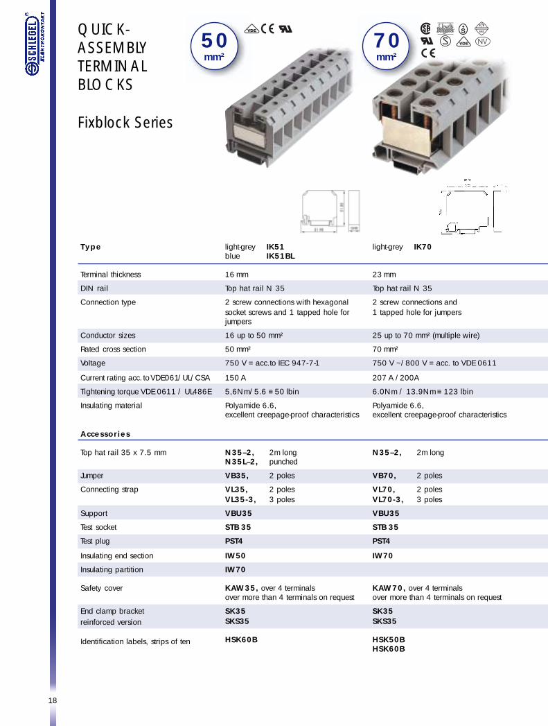
light-grey IK51blue IK51BL
16 mm
Top hat rail N 35
2 screw connections with hexagonalsocket screws and 1 tapped hole forjumpers
16 up to 50 mm²
50 mm²
750 V = acc.to IEC 947-7-1
150 A
5,6Nm/5.6 ≡ 50 lbin
Polyamide 6.6,excellent creepage-proof characteristics
N35–2, 2m longN35L–2, punched
VB35, 2 poles
VL35, 2 polesVL35-3, 3 poles
VBU35
STB 35
PST4
IW50
IW70
KAW35, over 4 terminalsover more than 4 terminals on request
SK35SKS35
HSK60B
5 0mm²
light-grey IK70
23 mm
Top hat rail N 35
2 screw connections and1 tapped hole for jumpers
25 up to 70 mm² (multiple wire)
70 mm²
750 V ~/800 V = acc. to VDE 0611
207 A /200A
6.0Nm / 13.9Nm ≡ 123 lbin
Polyamide 6.6,excellent creepage-proof characteristics
N35–2, 2m long
VB70, 2 poles
VL70, 2 polesVL70-3, 3 poles
VBU35
STB 35
PST4
IW70
KAW70, over 4 terminalsover more than 4 terminals on request
SK35SKS35
HSK50BHSK60B
7 0mm²
Type
Terminal thickness
DIN rail
Connection type
Conductor sizes
Rated cross section
Voltage
Current rating acc. to VDE061/UL/CSA
Tightening torque VDE 0611 / UL486E
Insulating material
Accessories
Top hat rail 35 x 7.5 mm
Jumper
Connecting strap
Support
Test socket
Test plug
Insulating end section
Insulating partition
Safety cover
End clamp bracketreinforced version
Identification labels, strips of ten
QUICK-ASSEMBLYTERMINALBLOCKS
Fixblock Series
19
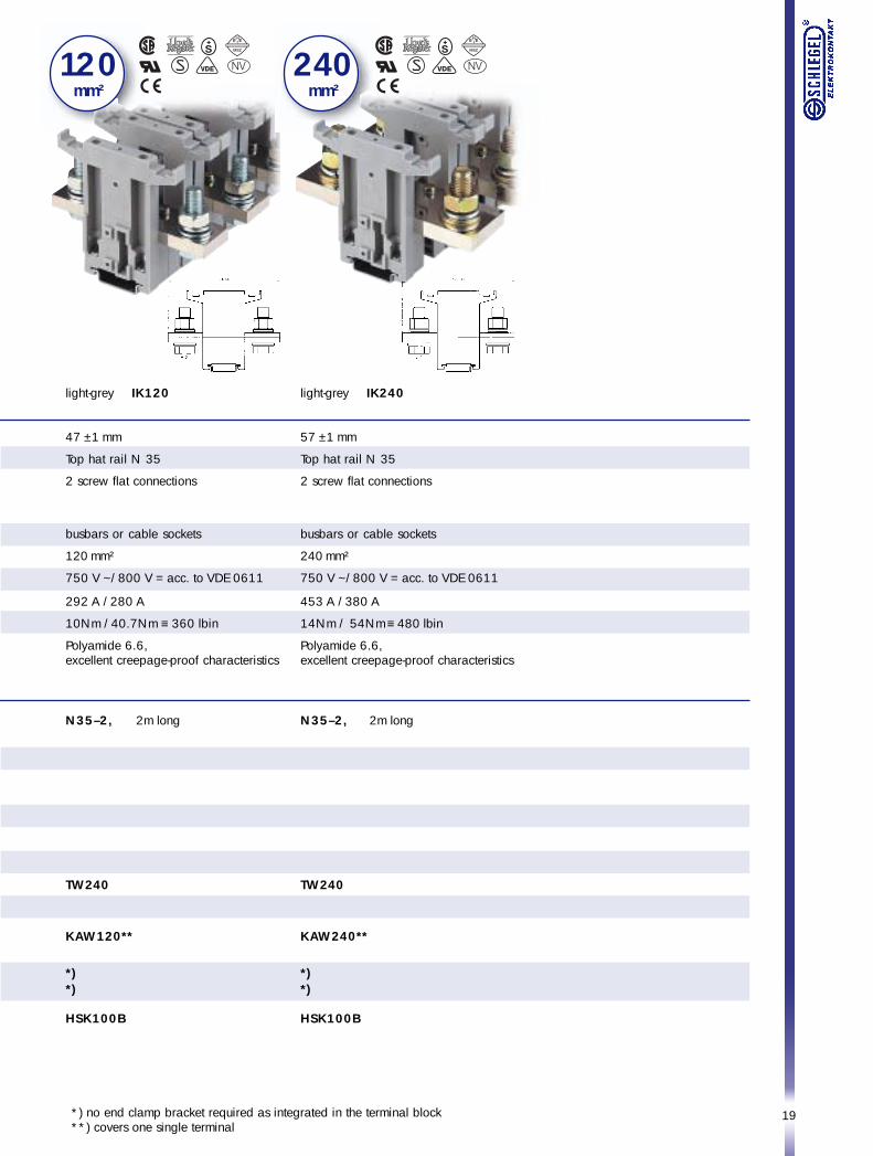
light-grey IK120
47 ±1 mm
Top hat rail N 35
2 screw flat connections
busbars or cable sockets
120 mm²
750 V ~/800 V = acc. to VDE 0611
292 A /280 A
10Nm /40.7Nm ≡ 360 lbin
Polyamide 6.6,excellent creepage-proof characteristics
N35–2, 2m long
TW240
KAW120**
*)*)
HSK100B
240 mm²
light-grey IK240
57 ±1 mm
Top hat rail N 35
2 screw flat connections
busbars or cable sockets
240 mm²
750 V ~/800 V = acc. to VDE 0611
453 A /380 A
14Nm / 54Nm ≡ 480 lbin
Polyamide 6.6,excellent creepage-proof characteristics
N35–2, 2m long
TW240
KAW240**
*)*)
HSK100B
*) no end clamp bracket required as integrated in the terminal block**) covers one single terminal
12 0 mm²
20
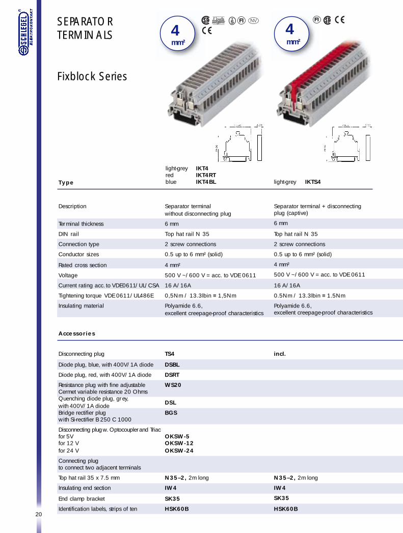
SEPARATORTERMINALS
Fixblock Series
light-grey IKTS4
Separator terminal + disconnectingplug (captive)
6 mm
Top hat rail N 35
2 screw connections
0.5 up to 6 mm² (solid)
4 mm²
500 V ~/600 V = acc. to VDE 0611
16 A/16A
0.5Nm / 13.3lbin ≡ 1.5Nm
Polyamide 6.6,excellent creepage-proof characteristics
incl.
N35–2, 2m long
IW4
SK35
HSK60B
4 mm²
Type
Description
Terminal thickness
DIN rail
Connection type
Conductor sizes
Rated cross section
Voltage
Current rating acc. to VDE0611/UL/CSA
Tightening torque VDE 0611/UL486E
Insulating material
Accessories
Disconnecting plug
Diode plug, blue, with 400V/1A diode
Diode plug, red, with 400V/1A diode
Resistance plug with fine adjustableCermet variable resistance 20 OhmsQuenching diode plug, grey,with 400V/1A diodeBridge rectifier plugwith Si-rectifier B 250 C 1000
Disconnecting plug w. Optocoupler and Triacfor 5Vfor 12 Vfor 24 V
Connecting plugto connect two adjacent terminals
Top hat rail 35 x 7.5 mm
Insulating end section
End clamp bracket
Identification labels, strips of ten
Separator terminalwithout disconnecting plug
6 mm
Top hat rail N 35
2 screw connections
0.5 up to 6 mm² (solid)
4 mm²
500 V ~/600 V = acc. to VDE 0611
16 A/16A
0,5Nm / 13.3lbin ≡ 1,5Nm
Polyamide 6.6,excellent creepage-proof characteristics
TS4
DSBL
DSRT
WS20
DSL
BGS
OKSW-5OKSW-12OKSW-24
N35–2, 2m long
IW4
SK35
HSK60B
4 mm²
light-grey IKT4red IKT4RTblue IKT4BL
21
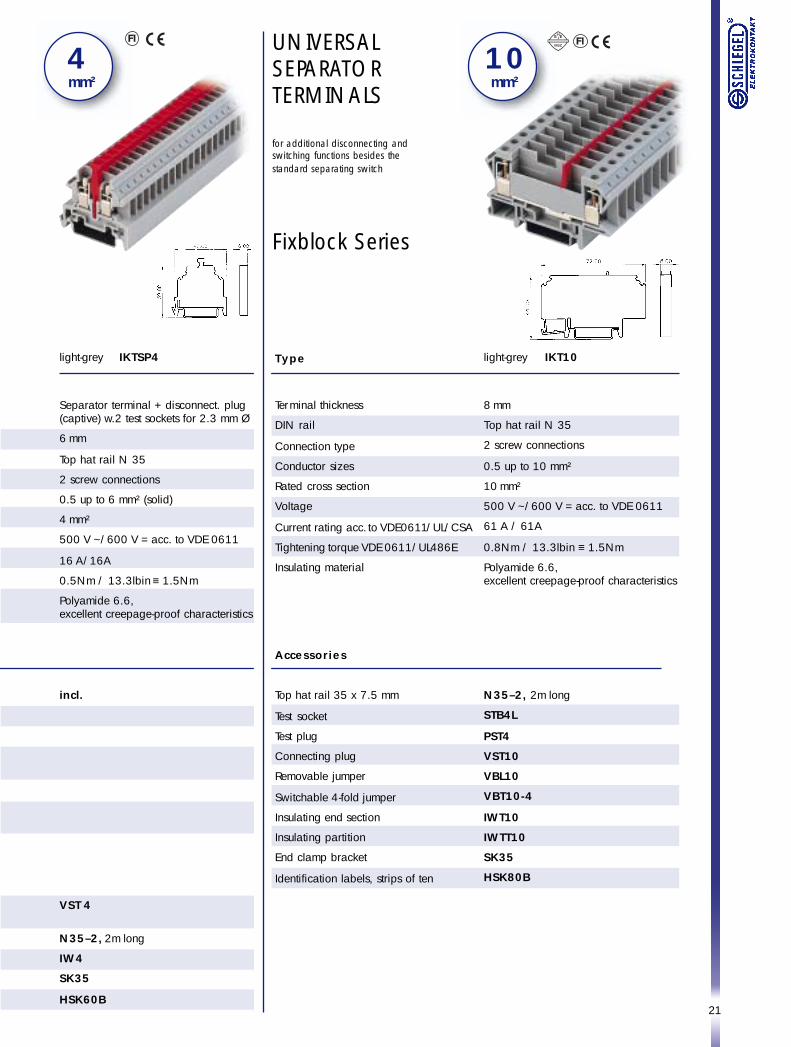
light-grey IKTSP4
Separator terminal + disconnect. plug(captive) w.2 test sockets for 2.3 mm Ø
6 mm
Top hat rail N 35
2 screw connections
0.5 up to 6 mm² (solid)
4 mm²
500 V ~/600 V = acc. to VDE 0611
16 A/16A
0.5Nm / 13.3lbin ≡ 1.5Nm
Polyamide 6.6,excellent creepage-proof characteristics
incl.
VST 4
N35–2, 2m long
IW4
SK35
HSK60B
4 mm²
UNIVERSALSEPARATORTERMINALS
for additional disconnecting andswitching functions besides thestandard separating switch
Fixblock Series
1 0 mm²
light-grey IKT10
8 mm
Top hat rail N 35
2 screw connections
0.5 up to 10 mm²
10 mm²
500 V ~/600 V = acc. to VDE 0611
61 A / 61A
0.8Nm / 13.3lbin ≡ 1.5Nm
Polyamide 6.6,excellent creepage-proof characteristics
N35–2, 2m long
STB4L
PST4
VST10
VBL10
VBT10-4
IWT10
IWTT10
SK35
HSK80B
Type
Terminal thickness
DIN rail
Connection type
Conductor sizes
Rated cross section
Voltage
Current rating acc. to VDE0611/UL/CSA
Tightening torque VDE 0611/UL486E
Insulating material
Accessories
Top hat rail 35 x 7.5 mm
Test socket
Test plug
Connecting plug
Removable jumper
Switchable 4-fold jumper
Insulating end section
Insulating partition
End clamp bracket
Identification labels, strips of ten
22
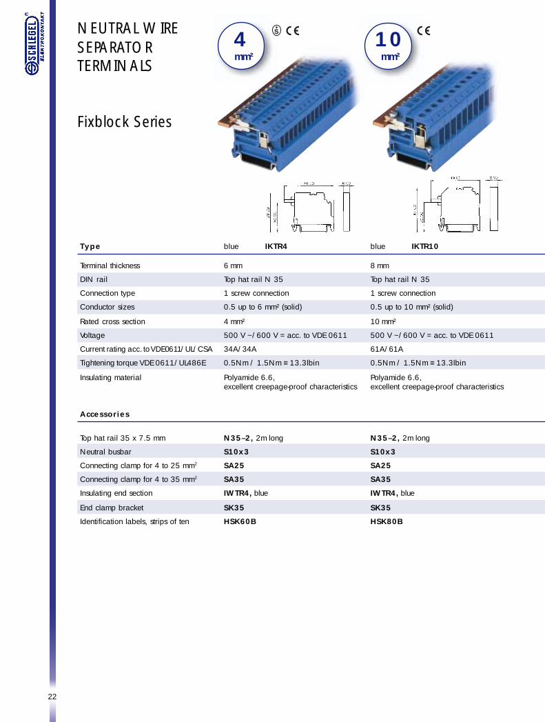
NEUTRAL WIRESEPARATORTERMINALS
Fixblock Series
blue IKTR4
6 mm
Top hat rail N 35
1 screw connection
0.5 up to 6 mm² (solid)
4 mm²
500 V ~/600 V = acc. to VDE 0611
34A/34A
0.5Nm / 1.5Nm ≡ 13.3lbin
Polyamide 6.6,excellent creepage-proof characteristics
N35–2, 2m long
S10x3
SA25
SA35
IWTR4, blue
SK35
HSK60B
4 mm²
Type
Terminal thickness
DIN rail
Connection type
Conductor sizes
Rated cross section
Voltage
Current rating acc. to VDE0611/UL/CSA
Tightening torque VDE 0611/UL486E
Insulating material
Accessories
Top hat rail 35 x 7.5 mm
Neutral busbar
Connecting clamp for 4 to 25 mm2
Connecting clamp for 4 to 35 mm2
Insulating end section
End clamp bracket
Identification labels, strips of ten
1 0 mm²
blue IKTR10
8 mm
Top hat rail N 35
1 screw connection
0.5 up to 10 mm² (solid)
10 mm²
500 V ~/600 V = acc. to VDE 0611
61A/61A
0.5Nm / 1.5Nm ≡ 13.3lbin
Polyamide 6.6,excellent creepage-proof characteristics
N35–2, 2m long
S10x3
SA25
SA35
IWTR4, blue
SK35
HSK80B
23
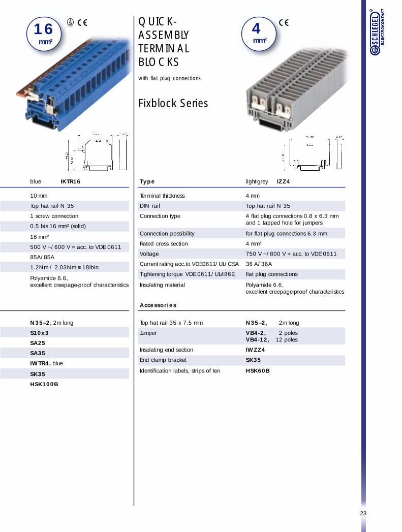
QUICK-ASSEMBLYTERMINALBLOCKSwith flat plug connections
Fixblock Series
1 6 mm²
light-grey IZZ4
4 mm
Top hat rail N 35
4 flat plug connections 0.8 x 6.3 mmand 1 tapped hole for jumpers
for flat plug connections 6.3 mm
4 mm²
750 V ~/800 V = acc. to VDE 0611
36 A/36A
flat plug connections
Polyamide 6.6,excellent creepage-proof characteristics
N35–2, 2m long
VB4-2, 2 polesVB4-12, 12 poles
IWZZ4
SK35
HSK60B
4 mm²
Type
Terminal thickness
DIN rail
Connection type
Connection possibility
Rated cross section
Voltage
Current rating acc. to VDE0611/UL/CSA
Tightening torque VDE 0611/UL486E
Insulating material
Accessories
Top hat rail 35 x 7.5 mm
Jumper
Insulating end section
End clamp bracket
Identification labels, strips of ten
blue IKTR16
10 mm
Top hat rail N 35
1 screw connection
0.5 bis 16 mm² (solid)
16 mm²
500 V ~/600 V = acc. to VDE 0611
85A/85A
1.2Nm / 2.03Nm ≡ 18lbin
Polyamide 6.6,excellent creepage-proof characteristics
N35–2, 2m long
S10x3
SA25
SA35
IWTR4, blue
SK35
HSK100B
24
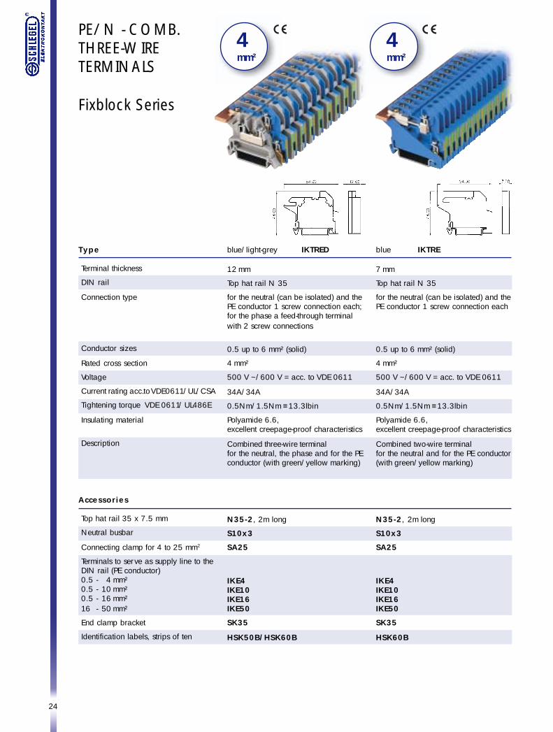
PE/N - COMB.THREE-WIRETERMINALS
Fixblock Series
blue/light-grey IKTRED
12 mm
Top hat rail N 35
for the neutral (can be isolated) and thePE conductor 1 screw connection each;for the phase a feed-through terminalwith 2 screw connections
0.5 up to 6 mm² (solid)
4 mm²
500 V ~/600 V = acc. to VDE 0611
34A/34A
0.5Nm/1.5Nm ≡ 13.3lbin
Polyamide 6.6,excellent creepage-proof characteristics
Combined three-wire terminalfor the neutral, the phase and for the PEconductor (with green/yellow marking)
N35-2, 2m long
S10x3
SA25
IKE4IKE10IKE16IKE50
SK35
HSK50B/HSK60B
Type
Terminal thickness
DIN rail
Connection type
Conductor sizes
Rated cross section
Voltage
Current rating acc. to VDE0611/UL/CSA
Tightening torque VDE 0611 / UL486E
Insulating material
Description
Accessories
Top hat rail 35 x 7.5 mm
Neutral busbar
Connecting clamp for 4 to 25 mm2
Terminals to serve as supply line to theDIN rail (PE conductor)0.5 - 4 mm²0.5 - 10 mm²0.5 - 16 mm²16 - 50 mm²
End clamp bracket
Identification labels, strips of ten
4 mm²
blue IKTRE
7 mm
Top hat rail N 35
for the neutral (can be isolated) and thePE conductor 1 screw connection each
0.5 up to 6 mm² (solid)
4 mm²
500 V ~/600 V = acc. to VDE 0611
34A/34A
0.5Nm/1.5Nm ≡ 13.3lbin
Polyamide 6.6,excellent creepage-proof characteristics
Combined two-wire terminalfor the neutral and for the PE conductor(with green/yellow marking)
N35-2, 2m long
S10x3
SA25
IKE4IKE10IKE16IKE50
SK35
HSK60B
4 mm²
25
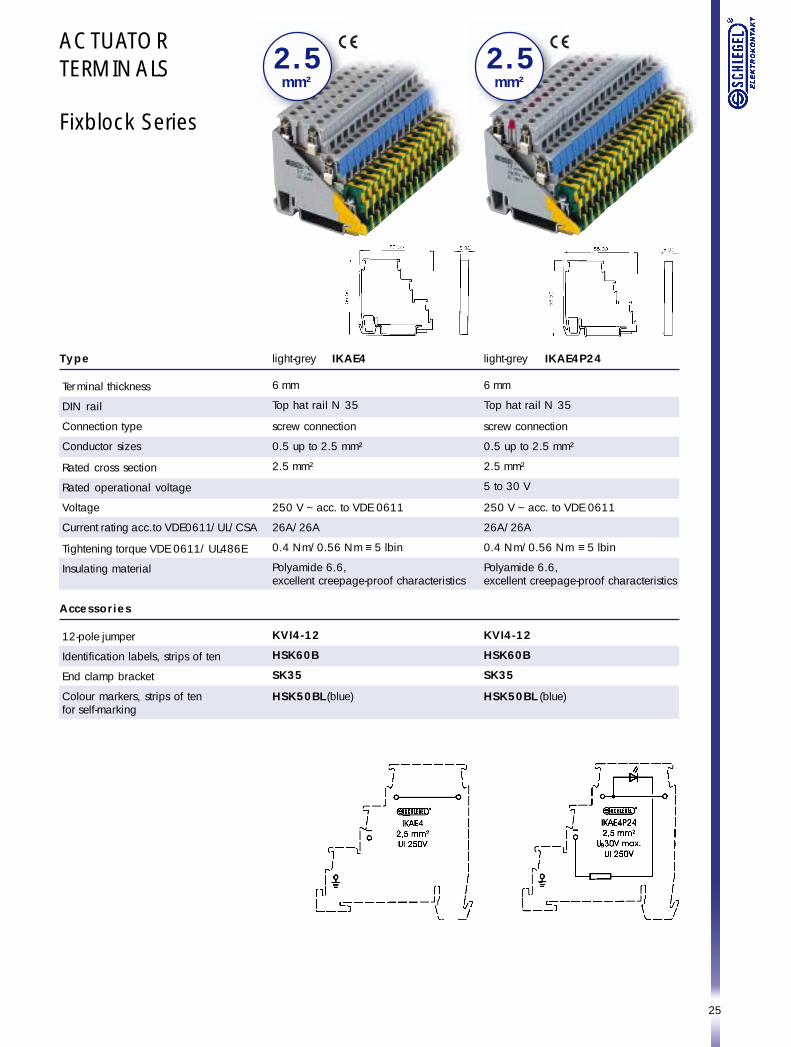
ACTUATORTERMINALS
Fixblock Series
Type
Terminal thickness
DIN rail
Connection type
Conductor sizes
Rated cross section
Rated operational voltage
Voltage
Current rating acc. to VDE0611/UL/CSA
Tightening torque VDE 0611 / UL486E
Insulating material
Accessories
12-pole jumper
Identification labels, strips of ten
End clamp bracket
Colour markers, strips of tenfor self-marking
light-grey IKAE4
6 mm
Top hat rail N 35
screw connection
0.5 up to 2.5 mm²
2.5 mm²
250 V ~ acc. to VDE 0611
26A/26A
0.4 Nm/0.56 Nm ≡ 5 lbin
Polyamide 6.6,excellent creepage-proof characteristics
KVI4-12
HSK60B
SK35
HSK50BL (blue)
light-grey IKAE4P24
6 mm
Top hat rail N 35
screw connection
0.5 up to 2.5 mm²
2.5 mm²
5 to 30 V
250 V ~ acc. to VDE 0611
26A/26A
0.4 Nm/0.56 Nm ≡ 5 lbin
Polyamide 6.6,excellent creepage-proof characteristics
KVI4-12
HSK60B
SK35
HSK50BL (blue)
2 . 5mm²
2 . 5mm²
26
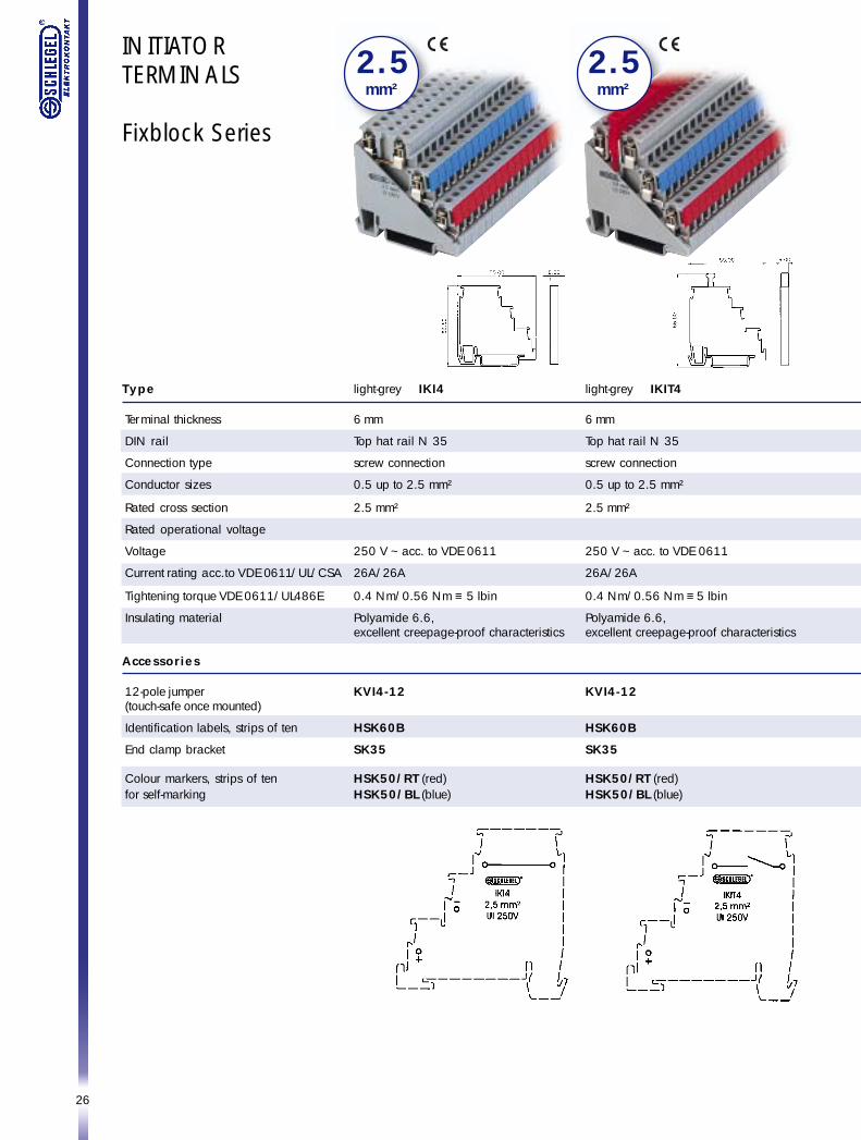
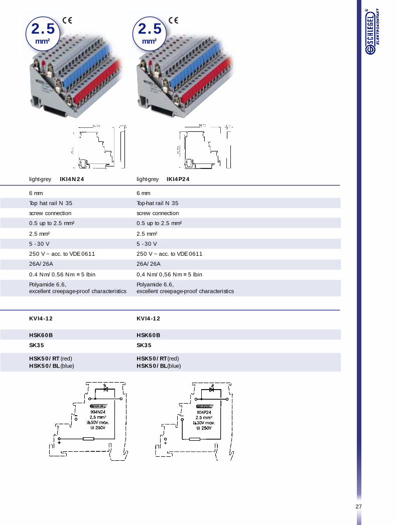
INITIATORTERMINALS
Fixblock Series
light-grey IKI4
6 mm
Top hat rail N 35
screw connection
0.5 up to 2.5 mm²
2.5 mm²
250 V ~ acc. to VDE 0611
26A/26A
0.4 Nm/0.56 Nm ≡ 5 lbin
Polyamide 6.6,excellent creepage-proof characteristics
KVI4-12
HSK60B
SK35
HSK50/RT (red)HSK50/BL (blue)
Type
Terminal thickness
DIN rail
Connection type
Conductor sizes
Rated cross section
Rated operational voltage
Voltage
Current rating acc. to VDE 0611/UL/CSA
Tightening torque VDE 0611/UL486E
Insulating material
Accessories
12-pole jumper(touch-safe once mounted)
Identification labels, strips of ten
End clamp bracket
Colour markers, strips of tenfor self-marking
light-grey IKIT4
6 mm
Top hat rail N 35
screw connection
0.5 up to 2.5 mm²
2.5 mm²
250 V ~ acc. to VDE 0611
26A/26A
0.4 Nm/0.56 Nm ≡ 5 lbin
Polyamide 6.6,excellent creepage-proof characteristics
KVI4-12
HSK60B
SK35
HSK50/RT (red)HSK50/BL (blue)
2 . 5mm²
2 . 5mm²
27
light-grey IKI4N24
6 mm
Top hat rail N 35
screw connection
0.5 up to 2.5 mm²
2.5 mm²
5 - 30 V
250 V ~ acc. to VDE 0611
26A/26A
0.4 Nm/0.56 Nm ≡ 5 lbin
Polyamide 6.6,excellent creepage-proof characteristics
KVI4-12
HSK60B
SK35
HSK50/RT (red)HSK50/BL (blue)
light-grey IKI4P24
6 mm
Top-hat rail N 35
screw connection
0.5 up to 2.5 mm²
2.5 mm²
5 - 30 V
250 V ~ acc. to VDE 0611
26A/26A
0,4 Nm/0,56 Nm ≡ 5 lbin
Polyamide 6.6,excellent creepage-proof characteristics
KVI4-12
HSK60B
SK35
HSK50/RT (red)HSK50/BL (blue)
2 . 5mm²
2 . 5mm²
28
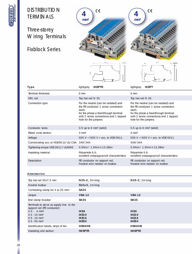
DISTRIBUTIONTERMINALS
Three-storeyWiring Terminals
Fixblock Series
4 mm²
4 mm²
light-grey IKEPTR
6 mm
Top hat rail N 35
For the neutral (can be isolated) andthe PE conductor 1 screw connectioneach;for the phase a feed-through terminalwith 2 screw connections and 1 tappedhole for the jumpers.
0.5 up to 6 mm² (solid)
4 mm²
500 V ~/600 V = acc. to VDE 0611
34A/34A
0.5Nm / 1.5Nm ≡ 13.3lbin
Polyamide 6.6,excellent creepage-proof characteristics
PE conductor on support rail,Neutral wire isolator on busbar
N35-2, 2m long
S10x3, 1m long
SA25
VB4-12
SK35
IKE4IKE10IKE16IKE50
HSK60B
IWEPTR
Type
Terminal thickness
DIN rail
Connection type
Conductor sizes
Rated cross section
Voltage
Current rating acc. to VDE 0611/UL/CSA
Tightening torque VDE 0611 / UL486E
Insulating material
Description
Accessories
Top hat rail 35x7.5 mm
Neutral busbar
Connecting clamp for 4 to 25 mm2
Jumper
End clamp bracket
Terminals to serve as supply line to thesupport rail (PE conductor)0.5 - 4 mm²0.5 - 10 mm²0.5 - 16 mm²0.5 - 50 mm²
Identification labels, strips of ten
Insulating end section
light-grey IKEPT
6 mm
Top hat rail N 35
For the neutral (can be isolated) andthe PE conductor 1 screw connectioneach;for the phase a feed-through terminalwith 2 screw connections and 1 tappedhole for the jumpers.
0.5 up to 6 mm² (solid)
4 mm²
500 V ~/600 V = acc. to VDE 0611
34A/34A
0.5Nm / 1.5Nm ≡ 13.3lbin
Polyamide 6.6,excellent creepage-proof characteristics
PE conductor on support rail,Neutral wire isolator on busbar
N35-2, 2m long
VB4-12
SK35
IKE4IKE10IKE16IKE50
HSK60B
IWEPTR
29
4 mm²
4 mm²
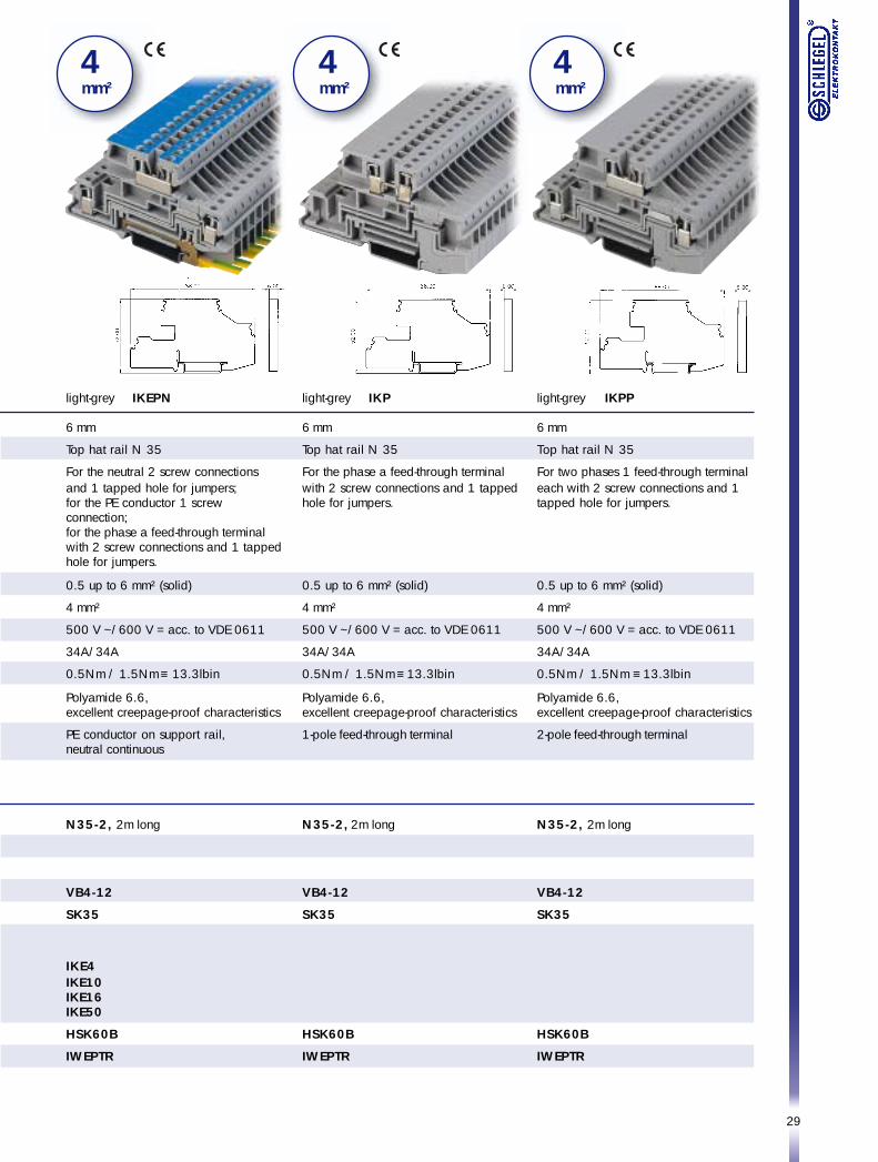
4 mm²
light-grey IKEPN
6 mm
Top hat rail N 35
For the neutral 2 screw connectionsand 1 tapped hole for jumpers;for the PE conductor 1 screwconnection;for the phase a feed-through terminalwith 2 screw connections and 1 tappedhole for jumpers.
0.5 up to 6 mm² (solid)
4 mm²
500 V ~/600 V = acc. to VDE 0611
34A/34A
0.5Nm / 1.5Nm ≡ 13.3lbin
Polyamide 6.6,excellent creepage-proof characteristics
PE conductor on support rail,neutral continuous
N35-2, 2m long
VB4-12
SK35
IKE4IKE10IKE16IKE50
HSK60B
IWEPTR
light-grey IKP
6 mm
Top hat rail N 35
For the phase a feed-through terminalwith 2 screw connections and 1 tappedhole for jumpers.
0.5 up to 6 mm² (solid)
4 mm²
500 V ~/600 V = acc. to VDE 0611
34A/34A
0.5Nm / 1.5Nm ≡ 13.3lbin
Polyamide 6.6,excellent creepage-proof characteristics
1-pole feed-through terminal
N35-2, 2m long
VB4-12
SK35
HSK60B
IWEPTR
light-grey IKPP
6 mm
Top hat rail N 35
For two phases 1 feed-through terminaleach with 2 screw connections and 1tapped hole for jumpers.
0.5 up to 6 mm² (solid)
4 mm²
500 V ~/600 V = acc. to VDE 0611
34A/34A
0.5Nm / 1.5Nm ≡ 13.3lbin
Polyamide 6.6,excellent creepage-proof characteristics
2-pole feed-through terminal
N35-2, 2m long
VB4-12
SK35
HSK60B
IWEPTR
30
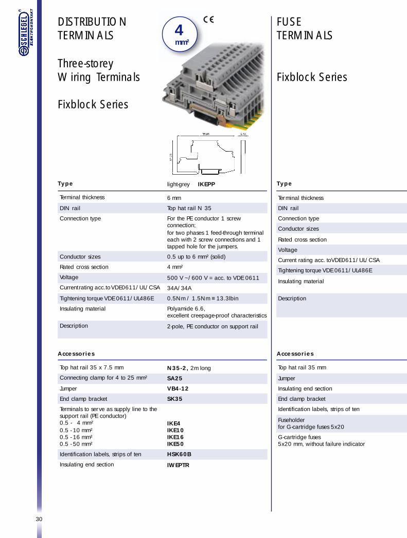
DISTRIBUTIONTERMINALS
Three-storeyWiring Terminals
Fixblock Series
4 mm²
FUSETERMINALS
Fixblock Series
Type
Terminal thickness
DIN rail
Connection type
Conductor sizes
Rated cross section
Voltage
Current rating acc. toVDE0611/UL/CSA
Tightening torque VDE 0611/UL486E
Insulating material
Description
Accessories
Top hat rail 35 mm
Jumper
Insulating end section
End clamp bracket
Identification labels, strips of ten
Fuseholderfor G-cartridge fuses 5x20
G-cartridge fuses5x20 mm, without failure indicator
Type
Terminal thickness
DIN rail
Connection type
Conductor sizes
Rated cross section
Voltage
Current rating acc. to VDE0611/UL/CSA
Tightening torque VDE 0611/UL486E
Insulating material
Description
Accessories
Top hat rail 35 x 7.5 mm
Connecting clamp for 4 to 25 mm²
Jumper
End clamp bracket
Terminals to serve as supply line to thesupport rail (PE conductor)0.5 - 4 mm²0.5 - 10 mm²0.5 - 16 mm²0.5 - 50 mm²
Identification labels, strips of ten
Insulating end section
light-grey IKEPP
6 mm
Top hat rail N 35
For the PE conductor 1 screwconnection;for two phases 1 feed-through terminaleach with 2 screw connections and 1tapped hole for the jumpers.
0.5 up to 6 mm² (solid)
4 mm²
500 V ~/600 V = acc. to VDE 0611
34A/34A
0.5Nm / 1.5Nm ≡ 13.3lbin
Polyamide 6.6,excellent creepage-proof characteristics
2-pole, PE conductor on support rail
N35-2, 2m long
SA25
VB4-12
SK35
IKE4IKE10IKE16IKE50
HSK60B
IWEPTR
31
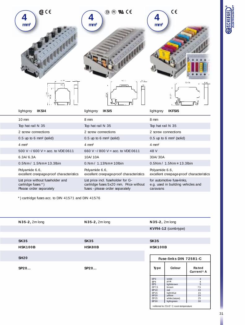
light-grey IKFSI5
8 mm
Top hat rail N 35
2 screw connections
0.5 up to 6 mm² (solid)
4 mm²
48 V
30A/30A
0.5Nm / 1.5Nm ≡ 13.3lbin
Polyamide 6.6,excellent creepage-proof characteristics
for automotive fuse-links,e.g. used in building vehicles andcaravans
N35-2, 2m long
KVFI4-12 (comb-type)
SK35
HSK100B
4 mm²
light-grey IKSI4
10 mm
Top hat rail N 35
2 screw connections
0.5 up to 6 mm² (solid)
4 mm²
500 V ~/600 V = acc. to VDE 0611
6.3A/6.3A
0.5Nm / 1.5Nm ≡ 13.3lbin
Polyamide 6.6,excellent creepage-proof characteristics
List price without fuseholder andcartridge fuses *)Please order separately
N35-2, 2m long
SK35
HSK100B
SH20
SP20...
4 mm²
4 mm²
light-grey IKSI5
8 mm
Top hat rail N 35
2 screw connections
0.5 up to 6 mm² (solid)
4 mm²
660 V ~/800 V = acc. to VDE 0611
10A/10A
0.Nm / 1.13Nm ≡ 10lbin
Polyamide 6.6,excellent creepage-proof characteristics
List price incl. fuseholder for G-cartridge fuses 5x20 mm. Price withoutfuses - please order separately
N35-2, 2m long
SK35
HSK80B
SP20...
*) cartridge fuses acc. to DIN 41571 and DIN 41576
RatedCurrent1) A
345
7,51015202530
Type
EP 3EP 4EP 5EP 7,5EP 10EP 15EP 20EP 25EP 30
Colour
violetpinklight-brownbrownredlight-blueyellowwhite (nature)light-green
1)referred to 23±5° C room temperature
Fuse-links DIN 72581-C
32
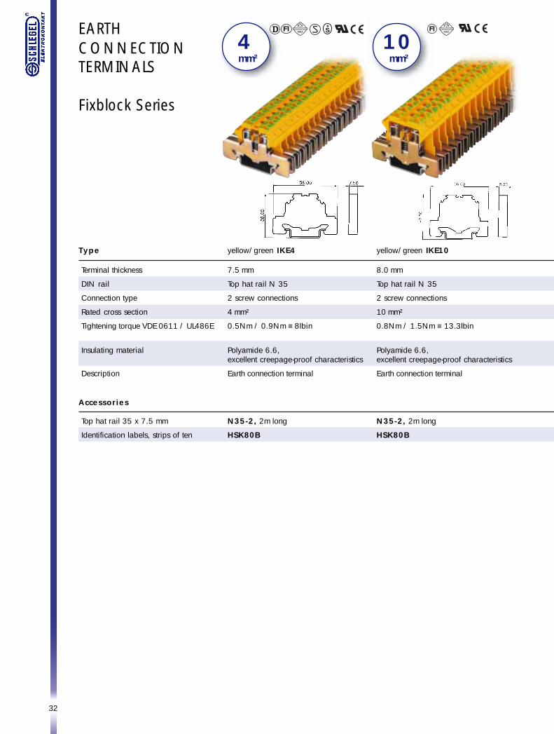
EARTHCONNECTIONTERMINALS
Fixblock Series
yellow/green IKE4
7.5 mm
Top hat rail N 35
2 screw connections
4 mm²
0.5Nm / 0.9Nm ≡ 8lbin
Polyamide 6.6,excellent creepage-proof characteristics
Earth connection terminal
N35-2, 2m long
HSK80B
4 mm²
Type
Terminal thickness
DIN rail
Connection type
Rated cross section
Tightening torque VDE 0611 / UL486E
Insulating material
Description
Accessories
Top hat rail 35 x 7.5 mm
Identification labels, strips of ten
yellow/green IKE10
8.0 mm
Top hat rail N 35
2 screw connections
10 mm²
0.8Nm / 1.5Nm ≡ 13.3lbin
Polyamide 6.6,excellent creepage-proof characteristics
Earth connection terminal
N35-2, 2m long
HSK80B
1 0 mm²
33
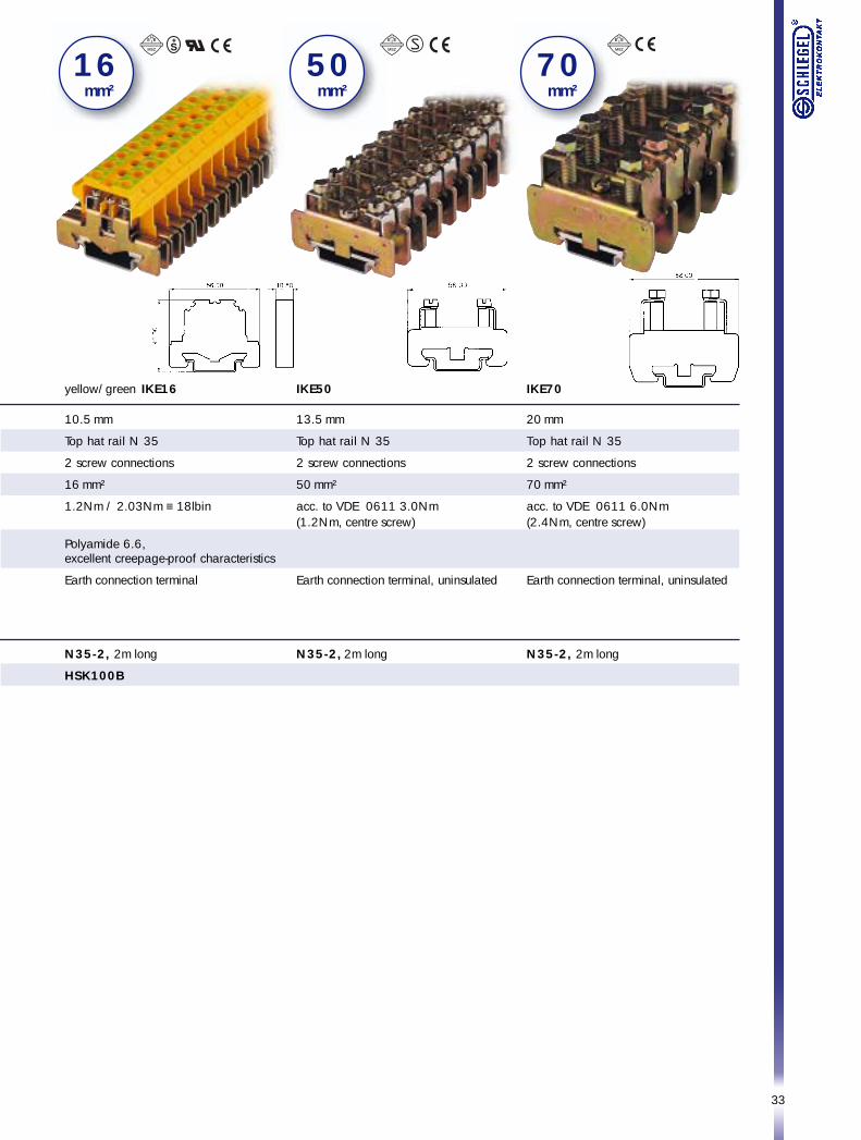
yellow/green IKE16
10.5 mm
Top hat rail N 35
2 screw connections
16 mm²
1.2Nm / 2.03Nm ≡ 18lbin
Polyamide 6.6,excellent creepage-proof characteristics
Earth connection terminal
N35-2, 2m long
HSK100B
1 6 mm²
5 0 mm²
7 0 mm²
IKE50
13.5 mm
Top hat rail N 35
2 screw connections
50 mm²
acc. to VDE 0611 3.0Nm(1.2Nm, centre screw)
Earth connection terminal, uninsulated
N35-2, 2m long
IKE70
20 mm
Top hat rail N 35
2 screw connections
70 mm²
acc. to VDE 0611 6.0Nm(2.4Nm, centre screw)
Earth connection terminal, uninsulated
N35-2, 2m long
34
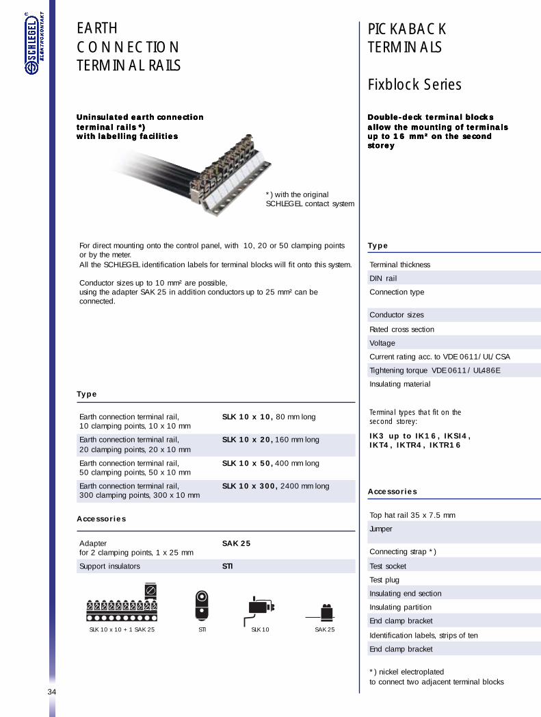
PICKABACKTERMINALS
Fixblock Series
Double-deck terminal blocksDouble-deck terminal blocksDouble-deck terminal blocksDouble-deck terminal blocksDouble-deck terminal blocksallow the mounting of terminalsallow the mounting of terminalsallow the mounting of terminalsallow the mounting of terminalsallow the mounting of terminalsup to 16 mm² on the secondup to 16 mm² on the secondup to 16 mm² on the secondup to 16 mm² on the secondup to 16 mm² on the secondstoreystoreystoreystoreystorey
Type
Terminal thickness
DIN rail
Connection type
Conductor sizes
Rated cross section
Voltage
Current rating acc. to VDE 0611/UL/CSA
Tightening torque VDE 0611 / UL486E
Insulating material
Terminal types that fit on thesecond storey:
IK3 up to IK16, IKSI4,IKT4, IKTR4, IKTR16
Accessories
Top hat rail 35 x 7.5 mm
Jumper
Connecting strap *)
Test socket
Test plug
Insulating end section
Insulating partition
End clamp bracket
Identification labels, strips of ten
End clamp bracket
*) nickel electroplatedto connect two adjacent terminal blocks
EARTHCONNECTIONTERMINAL RAILS
For direct mounting onto the control panel, with 10, 20 or 50 clamping pointsor by the meter.All the SCHLEGEL identification labels for terminal blocks will fit onto this system.
Conductor sizes up to 10 mm² are possible,using the adapter SAK 25 in addition conductors up to 25 mm² can beconnected.
Uninsulated earth connectionUninsulated earth connectionUninsulated earth connectionUninsulated earth connectionUninsulated earth connectionterminal rails *)terminal rails *)terminal rails *)terminal rails *)terminal rails *)with labelling facilitieswith labelling facilitieswith labelling facilitieswith labelling facilitieswith labelling facilities
*) with the originalSCHLEGEL contact system
SLK 10 x 10 + 1 SAK 25 STI SLK 10 SAK 25
Type
SLK 10 x 10, 80 mm long
SLK 10 x 20, 160 mm long
SLK 10 x 50, 400 mm long
SLK 10 x 300, 2400 mm long
Accessories
Adapterfor 2 clamping points, 1 x 25 mm
Support insulators
SAK 25
STI
Earth connection terminal rail,10 clamping points, 10 x 10 mm
Earth connection terminal rail,20 clamping points, 20 x 10 mm
Earth connection terminal rail,50 clamping points, 50 x 10 mm
Earth connection terminal rail,300 clamping points, 300 x 10 mm
35
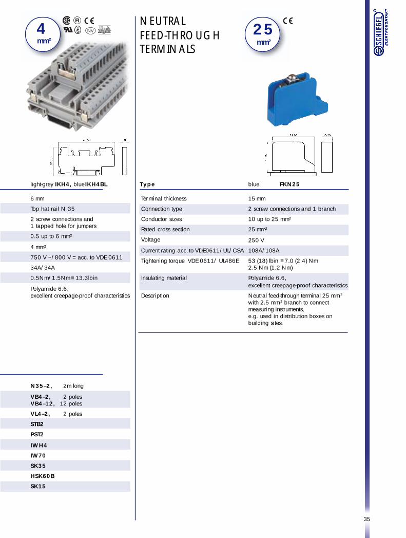
blue FKN25
15 mm
2 screw connections and 1 branch
10 up to 25 mm²
25 mm²
250 V
108A/108A
53 (18) lbin ≡ 7.0 (2.4) Nm2.5 Nm (1.2 Nm)
Polyamide 6.6,excellent creepage-proof characteristics
Neutral feed-through terminal 25 mm2
with 2.5 mm2 branch to connectmeasuring instruments,e.g. used in distribution boxes onbuilding sites.
2 5 mm²
NEUTRALFEED-THROUGHTERMINALS
Type
Terminal thickness
Connection type
Conductor sizes
Rated cross section
Voltage
Current rating acc. to VDE0611/UL/CSA
Tightening torque VDE 0611 / UL486E
Insulating material
Description
light-grey IKH4, blue IKH4BL
6 mm
Top hat rail N 35
2 screw connections and1 tapped hole for jumpers
0.5 up to 6 mm²
4 mm²
750 V ~/800 V = acc. to VDE 0611
34A/34A
0.5Nm/1.5Nm ≡ 13.3lbin
Polyamide 6.6,excellent creepage-proof characteristics
N35–2, 2m long
VB4–2, 2 polesVB4–12, 12 poles
VL4–2, 2 poles
STB2
PST2
IWH4
IW70
SK35
HSK60B
SK15
4 mm²
36
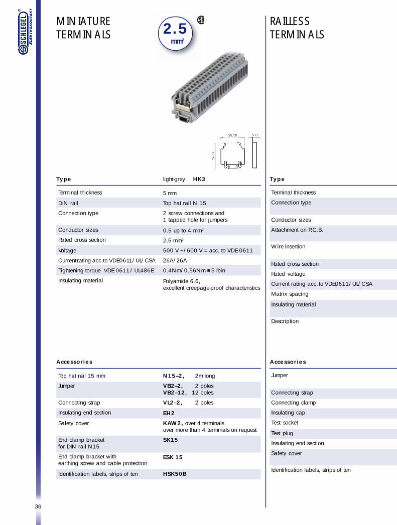
MINIATURETERMINALS 2 . 5
mm²
light-grey HK3
5 mm
Top hat rail N 15
2 screw connections and1 tapped hole for jumpers
0.5 up to 4 mm²
2.5 mm²
500 V ~/600 V = acc. to VDE 0611
26A/26A
0.4Nm/0.56Nm ≡ 5 lbin
Polyamide 6.6,excellent creepage-proof characteristics
N15–2, 2m long
VB2–2, 2 polesVB2–12, 12 poles
VL2–2, 2 poles
EH2
KAW2, over 4 terminalsover more than 4 terminals on request
SK15
ESK 15
HSK50B
Type
Terminal thickness
DIN rail
Connection type
Conductor sizes
Rated cross section
Voltage
Current rating acc. to VDE0611/UL/CSA
Tightening torque VDE 0611 / UL486E
Insulating material
Accessories
Top hat rail 15 mm
Jumper
Connecting strap
Insulating end section
Safety cover
End clamp bracketfor DIN rail N15
End clamp bracket withearthing screw and cable protection
Identification labels, strips of ten
RAILLESSTERMINALS
Type
Terminal thickness
Connection type
Conductor sizes
Attachment on P.C.B.
Wire insertion
Rated cross section
Rated voltage
Current rating acc. to VDE0611/UL/CSA
Matrix spacing
Insulating material
Description
Accessories
Jumper
Connecting strap
Connecting clamp
Insulating cap
Test socket
Test plug
Insulating end section
Safety cover
Identification labels, strips of ten
37
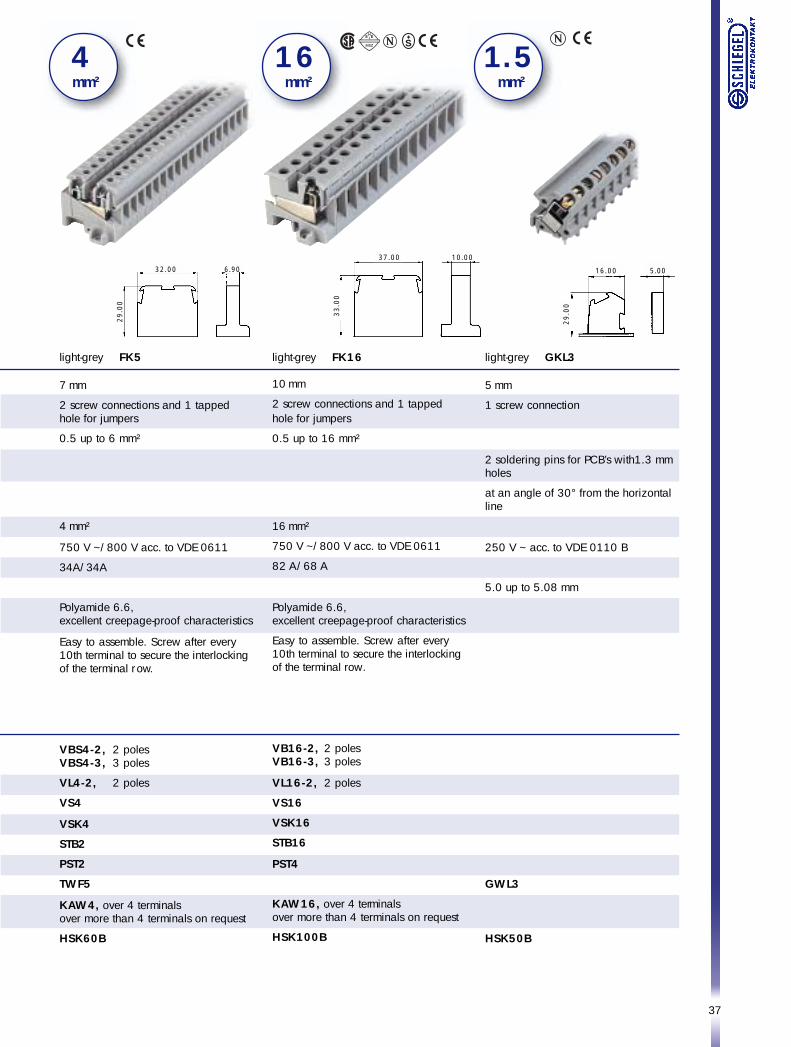
light-grey GKL3
5 mm
1 screw connection
2 soldering pins for PCB’s with1.3 mmholes
at an angle of 30° from the horizontalline
250 V ~ acc. to VDE 0110 B
5.0 up to 5.08 mm
GWL3
HSK50B
light-grey FK5
7 mm
2 screw connections and 1 tappedhole for jumpers
0.5 up to 6 mm²
4 mm²
750 V ~/800 V acc. to VDE 0611
34A/34A
Polyamide 6.6,excellent creepage-proof characteristics
Easy to assemble. Screw after every10th terminal to secure the interlockingof the terminal row.
VBS4-2, 2 polesVBS4-3, 3 poles
VL4-2, 2 poles
VS4
VSK4
STB2
PST2
TWF5
KAW4, over 4 terminalsover more than 4 terminals on request
HSK60B
4 mm²
light-grey FK16
10 mm
2 screw connections and 1 tappedhole for jumpers
0.5 up to 16 mm²
16 mm²
750 V ~/800 V acc. to VDE 0611
82 A/68 A
Polyamide 6.6,excellent creepage-proof characteristics
Easy to assemble. Screw after every10th terminal to secure the interlockingof the terminal row.
VB16-2, 2 polesVB16-3, 3 poles
VL16-2, 2 poles
VS16
VSK16
STB16
PST4
KAW16, over 4 terminalsover more than 4 terminals on request
HSK100B
1 6 mm²
1 . 5 mm²
32.00 6.90
29
.00
37.00 10.00
33
.00
16.00 5.00
29
.00
38
4 mm²
Type
Terminal thickness
DIN rail
Connection type
Conductor sizes
Rated cross section
Voltage
Current rating acc. to VDE 0611/UL
Tightening torque acc. to VDE 0611/UL486E
Insulating material
Accessories
Top hat rail 35 x 7.5 mm
Jumpers
Connecting straps
Test socket
Test plug
Insulating end section
Insulating partition
Safety cover
End clamp bracket
reinforced version
Identification labels, strips of ten
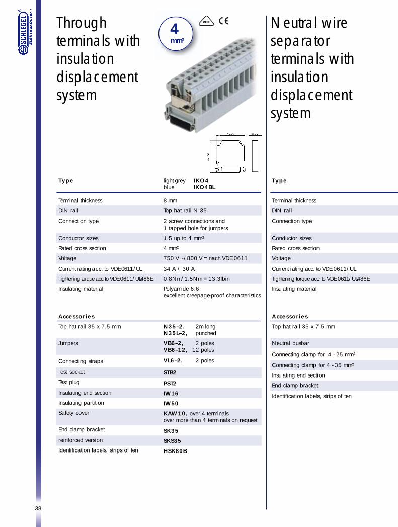
Throughterminals withinsulationdisplacementsystem
light-grey IKO4blue IKO4BL
8 mm
Top hat rail N 35
2 screw connections and1 tapped hole for jumpers
1.5 up to 4 mm²
4 mm²
750 V ~/800 V = nach VDE 0611
34 A / 30 A
0.8Nm/1.5Nm ≡ 13.3lbin
Polyamide 6.6,excellent creepage-proof characteristics
N35–2, 2m longN35L–2, punched
VB6–2, 2 polesVB6–12, 12 poles
VL6–2, 2 poles
STB2
PST2
IW16
IW50
KAW10, over 4 terminalsover more than 4 terminals on request
SK35
SKS35
HSK80B
Neutral wireseparatorterminals withinsulationdisplacementsystem
Type
Terminal thickness
DIN rail
Connection type
Conductor sizes
Rated cross section
Voltage
Current rating acc. to VDE 0611/UL
Tightening torque acc. to VDE 0611/UL486E
Insulating material
Accessories
Top hat rail 35 x 7.5 mm
Neutral busbar
Connecting clamp for 4 - 25 mm²
Connecting clamp for 4 - 35 mm²
Insulating end section
End clamp bracket
Identification labels, strips of ten
39
4 mm²
4 mm²
Earthconnectionterminals withinsulationdisplacementsystem
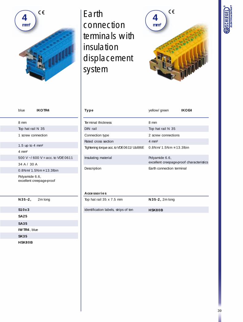
blue IKOTR4
8 mm
Top hat rail N 35
1 screw connection
1.5 up to 4 mm²
4 mm²
500 V ~/600 V = acc. to VDE 0611
34 A / 30 A
0.8Nm/1.5Nm ≡ 13.3lbin
Polyamide 6.6,excellent creepage-proof
N35–2, 2m long
S10x3
SA25
SA35
IWTR4, blue
SK35
HSK80B
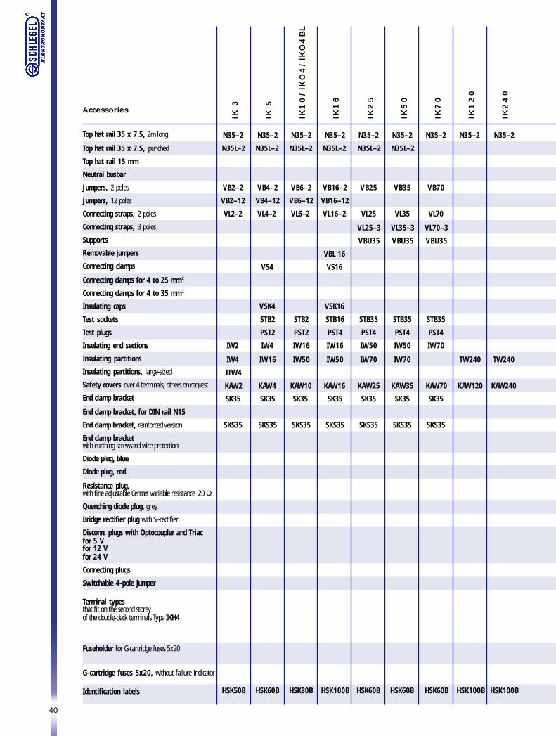
yellow/green IKOE4
8 mm
Top hat rail N 35
2 screw connections
4 mm²
0.8Nm/1.5Nm ≡ 13.3lbin
Polyamide 6.6,excellent creepage-proof characteristics
Earth connection terminal
N35-2, 2m long
HSK80B
Type
Terminal thickness
DIN rail
Connection type
Rated cross section
Tightening torque acc. to VDE 0611/UL486E
Insulating material
Description
Accessories
Top hat rail 35 x 7.5 mm
Identification labels, strips of ten
40
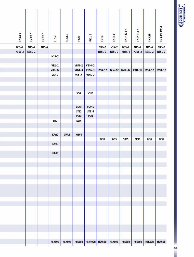
IK 3
IK 5
IK1
0/IK
O4
/IK
O4
BL
IK1
6
IK2
5
IK5
0
IK7
0
IK1
20
IK2
40
N35–2
N35L–2
VB2–2
VB2–12
VL2–2
IW2
IW4
ITW4
KAW2
SK35
SKS35
N35–2
N35L–2
VB4–2
VB4–12
VL4–2
VS4
VSK4
STB2
PST2
IW4
IW16
KAW4
SK35
SKS35
N35–2
N35L–2
VB6–2
VB6–12
VL6–2
STB2
PST2
IW16
IW50
KAW10
SK35
SKS35
N35–2
N35L–2
VB16–2
VB16–12
VL16–2
VBL 16
VS16
VSK16
STB16
PST4
IW16
IW50
KAW16
SK35
SKS35
N35–2
N35L–2
VB25
VL25
VL25–3
VBU35
STB35
PST4
IW50
IW70
KAW25
SK35
SKS35
N35–2
N35L–2
VB35
VL35
VL35–3
VBU35
STB35
PST4
IW50
IW70
KAW35
SK35
SKS35
N35–2
VB70
VL70
VL70–3
VBU35
STB35
PST4
IW70
KAW70
SK35
SKS35
N35–2
TW240
KAW120
N35–2
TW240
KAW240
HSK50B HSK60B HSK80B HSK100B HSK60B HSK60B HSK60B HSK100B HSK100B
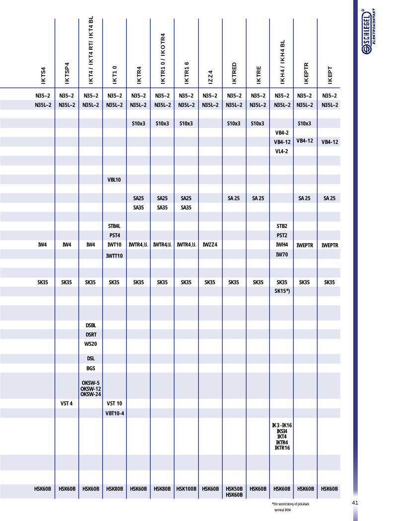
Accessories
Top hat rail 35 x 7.5, 2m long
Top hat rail 35 x 7.5, punched
Top hat rail 15 mm
Neutral busbar
Jumpers, 2 poles
Jumpers, 12 poles
Connecting straps, 2 poles
Connecting straps, 3 poles
Supports
Removable jumpers
Connecting clamps
Connecting clamps for 4 to 25 mm 2
Connecting clamps for 4 to 35 mm 2
Insulating caps
Test sockets
Test plugs
Insulating end sections
Insulating partitions
Insulating partitions, large-sized
Safety covers over 4 terminals, others on request
End clamp bracket
End clamp bracket, for DIN rail N15
End clamp bracket, reinforced version
End clamp bracketwith earthing screw and wire protection
Diode plug, blue
Diode plug, red
Resistance plug,with fine adjustable Cermet variable resistance 20 Ω
Quenching diode plug, grey
Bridge rectifier plug with Si-rectifier
Disconn. plugs with Optocoupler and Triacfor 5 Vfor 12 Vfor 24 V
Connecting plugs
Switchable 4-pole jumper
Terminal typesthat fit on the second storeyof the double-deck terminals Type IKH4
Fuseholder for G-cartridge fuses 5x20
G-cartridge fuses 5x20, without failure indicator
Identification labels
41
N35–2
N35L–2
IW4
SK35
N35–2
N35L–2
IW4
SK35
VST 4
N35–2
N35L–2
IW4
SK35
DSBL
DSRT
WS20
DSL
BGS
OKSW-5OKSW-12OKSW-24
N35–2
N35L–2
VBL10
STB4L
PST4
IWT10
IWTT10
SK35
VST 10
VBT10-4
N35–2
N35L–2
S10x3
SA 25
SK35
N35–2
N35L–2
S10x3
SA 25
SK35
N35–2
N35L–2
S10x3
SA25
SA35
IWTR4,bl.
SK35
N35–2
N35L–2
S10x3
SA25
SA35
IWTR4,bl.
SK35
N35–2
N35L–2
S10x3
SA25
SA35
IWTR4,bl.
SK35
N35–2
N35L–2
IWZZ4
SK35
N35–2
N35L–2
VB4-2
VB4-12
VL4-2
STB2
PST2
IWH4
IW70
SK35SK15*)
IK3 -IK16IKSI4IKT4IKTR4IKTR16
N35–2
N35L–2
S10x3
VB4-12
SA 25
IWEPTR
SK35
N35–2
N35L–2
VB4-12
SA 25
IWEPTR
SK35
IKTS
4
IKTS
P4
IKT4
/IK
T4RT/
IKT4
BL
IKT1
0
IKTR
4
IKTR
10
/IK
OTR
4
IKTR
16
IZZ4
IKTR
ED
IKTR
E
IKH4
/IK
H4
BL
IKEP
TR
IKEP
T
*)for second storey of pickaback
terminal IKH4
HSK60B HSK60B HSK60B HSK80B HSK60B HSK80B HSK100B HSK60B HSK50BHSK60B
HSK60B HSK60B HSK60B HSK60B
42
IKEP
N
IKP
IKPP
IKEP
P
IKSI4
IKSI5
IKFS
I5
IKE4
IKE1
0/IK
OE4
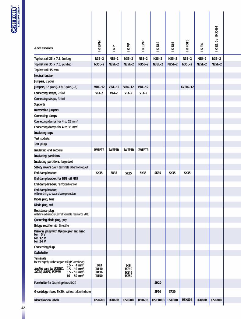
Top hat rail 35 x 7.5, 2m long
Top hat rail 35 x 7.5, punched
Top hat rail 15 mm
Neutral busbar
Jumpers, 2 poles
Jumpers, 12 poles (–12), 3 poles ( –3)
Connecting straps, 2-fold
Connecting straps, 3-fold
Supports
Removable jumpers
Connecting clamps
Connecting clamps for 4 to 25 mm2
Connecting clamps for 4 to 35 mm2
Insulating caps
Test sockets
Test plugs
Insulating end sections
Insulating partitions
Insulating partitions, large-sized
Safety covers over 4 terminals, others on request
End clamp bracket
End clamp bracket for DIN rail N15
End clamp bracket, reinforced version
End clamp bracket,with earthing screw and wire protection
Diode plug, blue
Diode plug, red
Resistance plug,with fine adjustable Cermet variable resistance 20 Ω
Quenching diode plug, grey
Bridge rectifier with Si-rectifier
Disconn. plug with Optocoupler and Triacfor 5 Vfor 12 Vfor 24 V
Connecting plugs
Switchable
Terminalsfor the supply to the support rail (PE conductor)
0.5 - 4 mm²0.5 - 10 mm²0.5 - 16 mm²16 - 50 mm²
Fuseholder for G-cartridge fuses 5x20
G-cartridge fuses 5x20, without failure indicator
Identification labels
N35–2
N35L–2
VB4–12
VL4-2
IWEPTR
SK35
IKE4IKE10IKE16IKE50
N35–2
N35L–2
VB4–12
VL4-2
IWEPTR
SK35
N35–2
N35L–2
VB4–12
VL4-2
IWEPTR
SK35
IKE4IKE10IKE16IKE50
N35–2
N35L–2
VB4–12
VL4-2
IWEPTR
SK35
N35–2
N35L–2
SK35
SH20
SP20
N35–2
N35L–2
KVFI4–12
SK35
N35–2
N35L–2
N35–2
N35L–2
SK35
SP20
N35–2
N35L–2
applies also to: IKTRED,IKTRE, IKEPT, IKEPTR
HSK60B HSK60B HSK60B HSK60B HSK100B HSK80B HSK80B HSK80B HSK80B
Accessories
43
N35–2
N35L–2
N35–2
N35L–2
N35–2
N15–2
VB2–2
VB2–12
VL2–2
EH2
KAW2
SK15
ESK15
GWL3
VBS4–2
VBS4–3
VL4–2
VS4
VSK4
STB2
PST2
TWF5
KAW4
VB16–2
VB16–3
VL16–2
VS16
VSK16
STB16
PST4
N35–2
N35L–2
KVI4–12
SK35
N35–2
N35L–2
KVI4–12
SK35
N35–2
N35L–2
KVI4–12
SK35
N35–2
N35L–2
KVI4–12
SK35
N35–2
N35L–2
KVI4–12
SK35
N35–2
N35L–2
KVI4–12
SK35
IKE1
6
IKE5
0
IKE7
0
HK3
GK
L3
FK5
FK16
IKI4
IKIT
4
IKI4
N24
IKI4
P2
4
IKA
E4
IKAE4
P2
4
HSK50B HSK50B HSK60B HSK100B HSK60B HSK60B HSK60B HSK60B HSK60B HSK60B
44
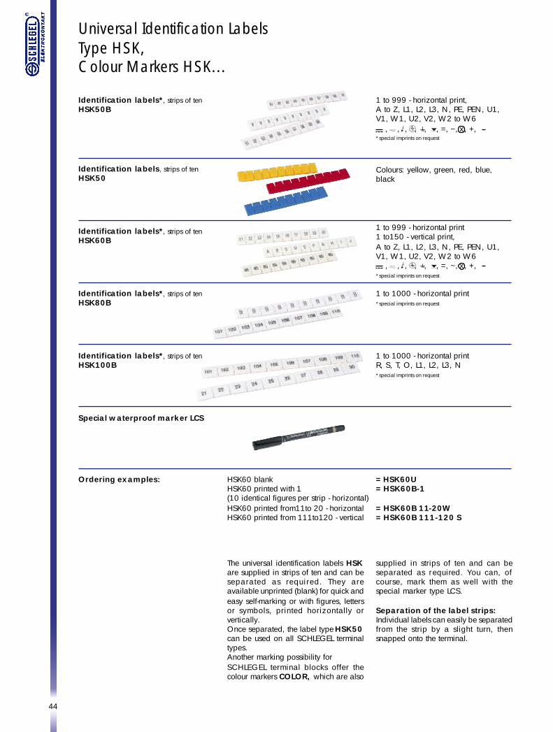
Universal Identification LabelsType HSK,Colour Markers HSK...
Identification labels*, strips of tenHSK50B
Identification labels, strips of tenHSK50
Identification labels*, strips of tenHSK60B
Identification labels*, strips of tenHSK80B
Identification labels*, strips of tenHSK100B
Special waterproof marker LCS
Ordering examples:
1 to 999 - horizontal print,A to Z, L1, L2, L3, N, PE, PEN, U1,V1, W1, U2, V2, W2 to W6
*special imprints on request
1 to 999 - horizontal print1 to150 - vertical print,A to Z, L1, L2, L3, N, PE, PEN, U1,V1, W1, U2, V2, W2 to W6
*special imprints on request
Colours: yellow, green, red, blue,black
1 to 1000 - horizontal print*special imprints on request
HSK60 blank = HSK60UHSK60 printed with 1 = HSK60B-1(10 identical figures per strip - horizontal)HSK60 printed from11to 20 - horizontal = HSK60B 11-20WHSK60 printed from 111to120 - vertical = HSK60B 111-120 S
The universal identification labels HSKare supplied in strips of ten and can beseparated as required. They areavailable unprinted (blank) for quick andeasy self-marking or with figures, lettersor symbols, printed horizontally orvertically.Once separated, the label type HSK50can be used on all SCHLEGEL terminaltypes.Another marking possibility forSCHLEGEL terminal blocks offer thecolour markers COLOR, which are also
1 to 1000 - horizontal printR, S, T, O, L1, L2, L3, N*special imprints on request
supplied in strips of ten and can beseparated as required. You can, ofcourse, mark them as well with thespecial marker type LCS.
Separation of the label strips:Individual labels can easily be separatedfrom the strip by a slight turn, thensnapped onto the terminal.
, , , , , , =, ~, x , +,
, , , , , , =, ~, x , +,
45
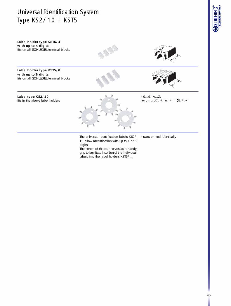
Universal Identification SystemType KS2/10 + KST5
Label holder type KST5/4with up to 4 digitsfits on all SCHLEGEL terminal blocks
Label holder type KST5/6with up to 6 digitsfits on all SCHLEGEL terminal blocks
*0...9, A...Z,Label type KS2/10fits in the above label holders
The universal identification labels KS2/10 allow identification with up to 4 or 6digits.The centre of the star serves as a handygrip to facilitate insertion of the individuallabels into the label holders KST5/...
*stars printed identically
, , , , , , =, ~, x , +,
46
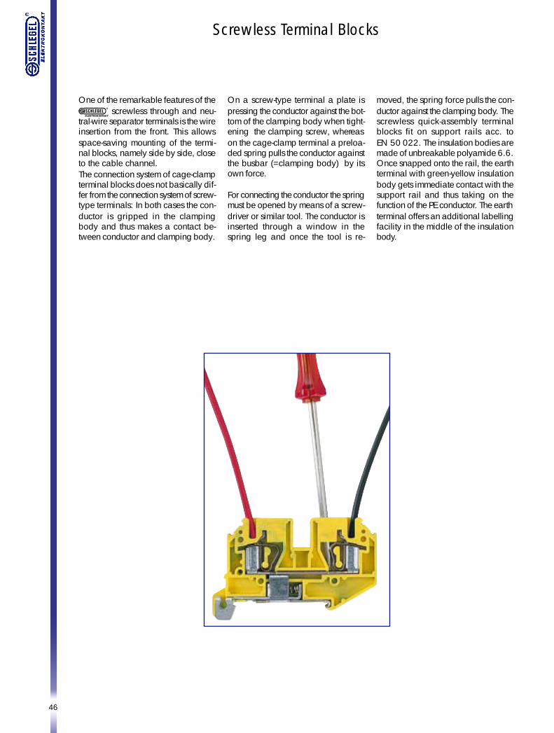
Screwless Terminal Blocks
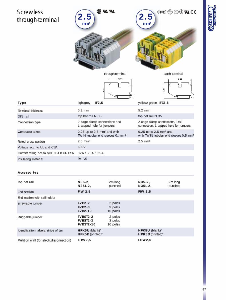
One of the remarkable features of the screwless through and neu-
tral-wire separator terminals is the wireinsertion from the front. This allowsspace-saving mounting of the termi-nal blocks, namely side by side, closeto the cable channel.The connection system of cage-clampterminal blocks does not basically dif-fer from the connection system of screw-type terminals: In both cases the con-ductor is gripped in the clampingbody and thus makes a contact be-tween conductor and clamping body.
On a screw-type terminal a plate ispressing the conductor against the bot-tom of the clamping body when tight-ening the clamping screw, whereason the cage-clamp terminal a preloa-ded spring pulls the conductor againstthe busbar (=clamping body) by itsown force.
For connecting the conductor the springmust be opened by means of a screw-driver or similar tool. The conductor isinserted through a window in thespring leg and once the tool is re-
moved, the spring force pulls the con-ductor against the clamping body. Thescrewless quick-assembly terminalblocks fit on support rails acc. toEN 50 022. The insulation bodies aremade of unbreakable polyamide 6.6.Once snapped onto the rail, the earthterminal with green-yellow insulationbody gets immediate contact with thesupport rail and thus taking on thefunction of the PE conductor. The earthterminal offers an additional labellingfacility in the middle of the insulationbody.
47
Screwlessthrough-terminal
light-grey IF2,5
5.2 mm
top hat rail N 35
2 cage clamp connections and1 tapped hole for jumpers
0.25 up to 2.5 mm² and withTWIN tubular end sleeves 0,. mm²
2.5 mm²
600V
32A / 20A / 25A
PA - V0
N35-2, 2m longN35L-2, punched
FIW 2,5
FVB2-2 2 polesFVB2-3 3 polesFVB2-10 10 poles
FVBST2-2 2 polesFVBST2-3 3 polesFVBST2-10 10 poles
HPK5U (blank)*HPK5B (printed)*
FITW2,5
2 . 5 mm²
Type
Terminal thickness
DIN rail
Connection type
Conductor sizes
Rated cross section
Voltage acc. to UL and CSA
Current rating acc.to VDE 0611/UL/CSA
Insulating material
Accessories
Top hat rail
End section
End section with rail-holder
screwable jumper
Pluggable jumper
Identification labels, strips of ten
Partition wall (for electr.disconnection)
2 . 5 mm²
yellow/green IFE2,5
5.2 mm
top hat rail N 35
2 cage clamp connections, 1railconnection, 1 tapped hole for jumpers
0.25 up to 2.5 mm² andwith TWIN tubular end sleeves 0.5 mm²
2.5 mm²
N35-2, 2m longN35L-2, punched
FIW 2,5
HPK5U (blank)*HPK5B (printed)*
FITW2,5
through-terminal earth terminal
48
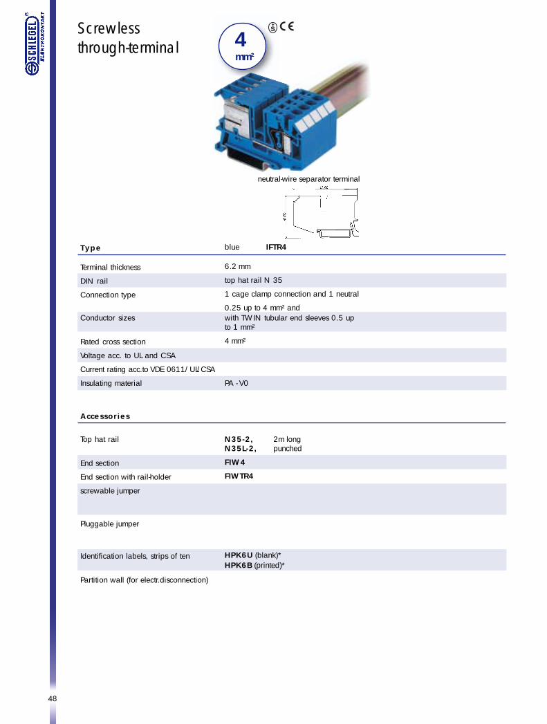
Screwlessthrough-terminal
Type
Terminal thickness
DIN rail
Connection type
Conductor sizes
Rated cross section
Voltage acc. to UL and CSA
Current rating acc.to VDE 0611/UL/CSA
Insulating material
Accessories
Top hat rail
End section
End section with rail-holder
screwable jumper
Pluggable jumper
Identification labels, strips of ten
Partition wall (for electr.disconnection)
4 mm²
blue IFTR4
6.2 mm
top hat rail N 35
1 cage clamp connection and 1 neutral
0.25 up to 4 mm² andwith TWIN tubular end sleeves 0.5 upto 1 mm²
4 mm²
PA - V0
N35-2, 2m longN35L-2, punched
FIW4
FIWTR4
HPK6U (blank)*HPK6B (printed)*
neutral-wire separator terminal

49

50