E -Z PACK DIE - Power & Signal Group - Electronic ... Pack...E -Z PACK SETUP PROCEDURE E-Z Pack Die...
15
DIE SETUP PROCEDURE E-Z PACK DIE
Transcript of E -Z PACK DIE - Power & Signal Group - Electronic ... Pack...E -Z PACK SETUP PROCEDURE E-Z Pack Die...

DIE SETUP PROCEDURE
E-Z PACK DIE

E-Z PACK SETUP PROCEDURE
E-Z Pack Die - 1 15-Jan-99
Major Components of Die
1. SHANK
2. LOWER MODULE
3. BRAKE LEVER (OR PIN)
4. CRIMP STATION
5. FRONT DEPRESSOR
6. CUTOFF BLOCK INSERT
7. CUTOFF PUNCH
8. FEED FINGER
9. FEED FINGER ADJUSTER SCREW
10. FRONT STOCK GUIDE
11. CRIMP PLATES
12. STOCK SUPPORT PLATE
13. ADJUSTER SCREW
14. UPPER MODULE
15. GUIDE RAIL SPACER
16. LATCH FOR SUBTOOL ASSEMBLY
Figure 1-2 Figure 1-3
5
1
Figure 1-1
1
2 3
8
9
10
13
12
NOTE: This manual applies to the installation and operation of the E-Z Pack die on a Speed-O-Matic press.
6
7
14
4
15
16
11

E-Z PACK SETUP PROCEDURE
E-Z Pack Die - 2 15-Jan-99
Terminal Insertion/Front Hook Rail Setup
Steps Procedure 1. Release Brake Latch (up position) (Figure 2-1). 2. Turn Latch for Subtool Assembly, CCW ¼ turn, then remove Guide and Brake
Subtool Assembly to adjust Hook Rail (Figure 2-2). 3. Loosen Front Hook Rail and Guide Rail Spacer screws (Figure 2-3). 4. Insert Terminals into the Guide and Brake Subtool Assembly so that the Hook
Rail is between the insulation and core wings (Figure 2-4). 5. Adjust Front Hook Rail up or down until it lightly touches the Terminals and
tighten screws (Figure 2-7) (Check terminal movement). 6. Move Guide Rail Spacer to insure the insulation wings are lightly touching the
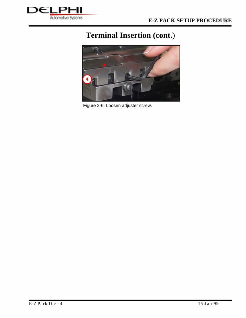
Front Stock Guide and tighten the Guide Rail Spacer screw (Figure 2-6) (Check terminal movement).
7. Reinsert Guide and Brake Subtool Assembly, then push and turn Latch for Subtool Assembly, ¼ turn, to lock.
8. Check terminal movement.
NOTE: Some setups may require the Hook Rail between the body and core wings.
Terminal Insertion Trouble Shooting
Trouble Possible Cause Correction Terminals too tight. Loosen Front Hook Rail and Stock
Guide. See steps above and Figure 2-3.
Terminals inserting partially & stopping.
Terminal reel needs adjustment, cutoff sticking, or Brake and/or Feed Finger not released.
See steps above.
Terminals inserting partially & stopping.
Burr or wrinkle on terminal carrier. Cut terminal carrier strip and see Step 4.
Terminals sticking during insertion.
Terminal track area dirty or damaged. Brake and Stock Guides are dirty or out of adjustment.
Remove Rear Hook Rail and Stock Guide. Clean and inspect for damage.
Terminals stopping before crimp station.
Check to ensure the Cutoff Punch is in the up position.
Press down on Cutoff Punch for movement and check Spring.
Terminals not fitting into the module.
Incorrect Subtool tooling and/or Stock Guide.
Check Subtool numbers with bill of material.

E-Z PACK SETUP PROCEDURE
E-Z Pack Die - 3 15-Jan-99
Terminal Insertion (cont.) 1. BRAKE LATCH
2. FEED FINGER
3. HOOK RAIL
4. FRONT STOCK GUIDE (Figure 2-6)
5. HOOK RAIL SCREWS (3)
6. FRONT STOCK GUIDE SCREW
7. LATCH FOR SUBTOOL ASSEMBLY
8. GUIDE RAIL SPACER SCREW
Figure 2-1: Release Brake.
1
Figure 2-4: Reinsert guide and brake tool assembly.
2
Figure 2-3: Loosen screws.
3
Figure 2-2: Remove guide and brake subtool assembly.
5
Figure 2-5: Front hook rail should lightly touch the terminals.
6
7
8
E-Z PACK SETUP PROCEDURE
E-Z Pack Die - 4 15-Jan-99
Terminal Insertion (cont.)
Figure 2-6: Loosen adjuster screw.
4
E-Z PACK SETUP PROCEDURE
E-Z Pack Die - 5 15-Jan-99
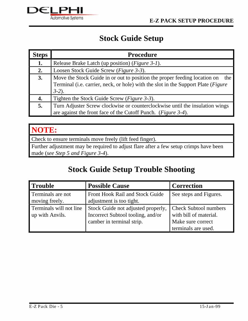
Stock Guide Setup
Steps Procedure 1. Release Brake Latch (up position) (Figure 3-1). 2. Loosen Stock Guide Screw (Figure 3-3). 3. Move the Stock Guide in or out to position the proper feeding location on the
Terminal (i.e. carrier, neck, or hole) with the slot in the Support Plate (Figure 3-2).
4. Tighten the Stock Guide Screw (Figure 3-3). 5. Turn Adjuster Screw clockwise or counterclockwise until the insulation wings
are against the front face of the Cutoff Punch. (Figure 3-4).
NOTE:
Check to ensure terminals move freely (lift feed finger). Further adjustment may be required to adjust flare after a few setup crimps have been made (see Step 5 and Figure 3-4).
Stock Guide Setup Trouble Shooting
Trouble Possible Cause Correction Terminals are not moving freely.
Front Hook Rail and Stock Guide adjustment is too tight.
See steps and Figures.
Terminals will not line up with Anvils.
Stock Guide not adjusted properly, Incorrect Subtool tooling, and/or camber in terminal strip.
Check Subtool numbers with bill of material. Make sure correct terminals are used.
E-Z PACK SETUP PROCEDURE
E-Z Pack Die - 6 15-Jan-99
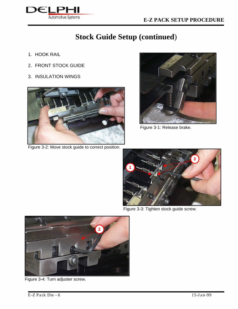
Stock Guide Setup (continued)
1. HOOK RAIL
2. FRONT STOCK GUIDE 3. INSULATION WINGS
Figure 3-1: Release brake.
Figure 3-2: Move stock guide to correct position.
Figure 3-4: Turn adjuster screw.
2
Figure 3-3: Tighten stock guide screw.
1
3

E-Z PACK SETUP PROCEDURE
E-Z Pack Die - 7 15-Jan-99
Die To Press Installation
Steps Procedure
1. Remove press Bolster Plate. 2. Before installing the die into the Press, turn the lettered dial until the letter
“D” is at the top, then turn the numbered dial until the number “4” is at the top.
3. Add Ram adapter to the press ensuring the adapter is fully seated (Figure 4-2).
4. Tighten Ram Clamp screws (Figure 4-3). 5. Place the Die in the press making sure the Cover Plate on the slide head is
inserted into the Ram adapter. 6. Install two mounting screws to the Plate Clamp (leaving them loose) (Figure
4-4). 7. Cycle the press by hand, 180° counterclockwise (Figure 4-5). 8. Tighten the mounting screws on the Plate Clamp to the bed of the press
(Figure 4-4). 6. Cycle the press once by hand, counterclockwise, until it clicks, to ensure the
press cycles freely.
NOTE:
If the Press does not rotate 180° in the CCW direction, loosen the two cap screws on the Connecting Rod Clamp. Turn Ball Screw to the right to increase and to the left to decrease. After adjustment, retighten the cap screws Ensure the press base and bottom of the die is clean.
Special Adapters for Presses
• MODULAR CUTTER KIT Plate Clamp Guard
• AMP KIT
Keeper Shank Guard Assembly Plate Clamp
• MECAL KIT Guard Assembly Plate Clamp

E-Z PACK SETUP PROCEDURE
E-Z Pack Die - 8 15-Jan-99
Die To Press Installation (continued)
1. RAM CLAMP
2. RAM ADAPTOR
3. MOUNTING SCREWS
1
Figure 4-2: Add ram adapter to die.
Figure 4-1
2
3
Figure 4-4: Install two mounting screws. Figure 4-3: Add ram adapter to die.

E-Z PACK SETUP PROCEDURE
E-Z Pack Die - 9 15-Jan-99
Die To Press Installation (continued)
Figure 4-5: Rotate press 180° CCW.

E-Z PACK SETUP PROCEDURE
E-Z Pack Die - 10 15-Jan-99
Progression Setup for Manual Cam
Steps Procedure 1. Remove upper module (Figure 5-1). 2. Loosen Feed Shaft to adjust the Feed Finger Shaft in or out until the feed
finger insert rides in the proper support plate slot (Figure 5-2). 3. Apply the Brake, making sure the slide head is in the down position. 4. Cycle the Press by hand 180° counterclockwise to advance terminals (Figure
5-3). 5. Cycle the Press to determine if the terminals need to be adjusted to the
left or right, depending on the terminal wings alignment with the Anvils. 6. Loosen the Feed Finger set screw while the tool pack holder slide is in the up
position (Figure 5-4).
7. Turn the Feed Finger Adjuster counterclockwise until the terminals are centered over the anvils (Figure 5-5).
8. Tighten Feed Finger Adjuster screw (Figure 5-4). 9. Reinstall upper module.
NOTE:
Feed (progression) is pre-set by using the correct feed cam listed on the Terminal ID sheet. Although, the majority of the adjustment is set using the cam, some minor adjustments may be needed. When running an Automatic Cam the slide head will be in the down position to advance the terminals.
Progression Setup for Manual Cam Trouble Shooting
Trouble Possible Cause Correction Under or Over Feeding Brake too loose or too tight.
Progression set wrong Tighten or loosen and/or reset progression.
Terminals not feeding Stock Guide too loose or too tight. Broken or worn feed finger, broken feed spring and or bent terminals.
Replace broken or worn parts and/or cut off bad section of terminals.

E-Z PACK SETUP PROCEDURE
E-Z Pack Die - 11 15-Jan-99
Progression Setup for Manual Cam (continued)
1. UPPER MODULE 2. FEED FINGER SHAFT 3. STOCK SUPPORT PLATE 4. BRAKE LATCH 5. TERMINALS 6. FEED FINGER 7. FEED FINGER ADJUSTER SCREW 8. FEED CAM Figure 5-1: Remove upper module.
Figure 5-2: Loosen feed shaft.
Figure 5-3: Cycle ram 180°.
1
2
3 4
6

E-Z PACK SETUP PROCEDURE
E-Z Pack Die - 12 15-Jan-99
Progression Setup for Manual Cam (continued)
Figure 5-4: Loosen feed finger set screw.
Figure 5-5: Turn feed finger adjuster screw.
5
7
8
E-Z PACK SETUP PROCEDURE
E-Z Pack Die - 13 15-Jan-99
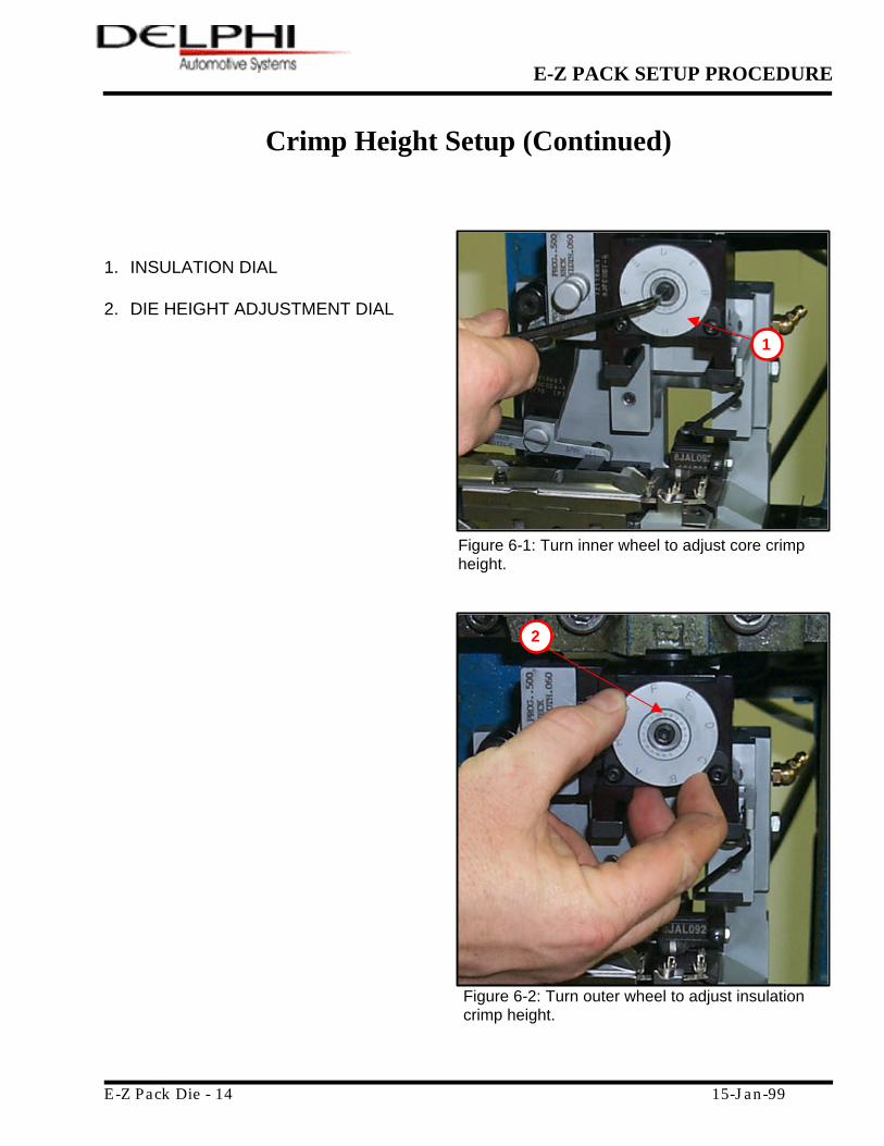
Crimp Height Setup
Steps Procedure
1. To adjust Core Crimp Height (CCH) and Insulation Crimp Height (IH), turn the Die Height Adjustment Dial (numbered 0-19) (Figure 6-1). The higher the number the tighter the crimp (19 is high/tight and 0 is loose).
2. To adjust Insulation Height, turn the Insulation Dial (dial lettered "A" - "H") (Figure 6-2).
3. To increase Insulation Height, turn the dial counterclockwise. To decrease Insulation Height, rotate the dial clockwise.
NOTES:
For CCH each mark / click on the index dial equals .001 inches For IH each mark / click on the index dial equals .005 inches The smaller, numbered dial adjusts the CCH and the IH proportionally. The larger, lettered dial adjusts only the insulation height. For nominal setting, turn the lettered dial until the letter “D” is at the top, then turn the numbered dial until the number “4” is at the top. Check Core and Insulation crimp height until the correct crimp height is met.
Crimp Height Trouble Shooting
Trouble Possible Cause Correction Crimp height changes in the middle of the run.
Check for broken Crimp Tooling. Replace Crimp Tools.
E-Z PACK SETUP PROCEDURE
E-Z Pack Die - 14 15-Jan-99
Crimp Height Setup (Continued) 1. INSULATION DIAL 2. DIE HEIGHT ADJUSTMENT DIAL
Figure 6-1: Turn inner wheel to adjust core crimp height.
Figure 6-2: Turn outer wheel to adjust insulation crimp height.
1
2