E-Space - ecs.umass.edu · • Board members include Intel, Samsung, WiTricity • WiTricity •...
21
E-Space Jonathan Scharf, Spencer Pietryka, Steve Bevacqua
Transcript of E-Space - ecs.umass.edu · • Board members include Intel, Samsung, WiTricity • WiTricity •...
E-SpaceJonathan Scharf, Spencer Pietryka, Steve Bevacqua

Statement of Problem
• Electronic devices more portable than ever
• Electronics technology outpaces battery technology
• Need to charge often or use many batteries
Battery Energy Density Transistor Count
Time (Year)
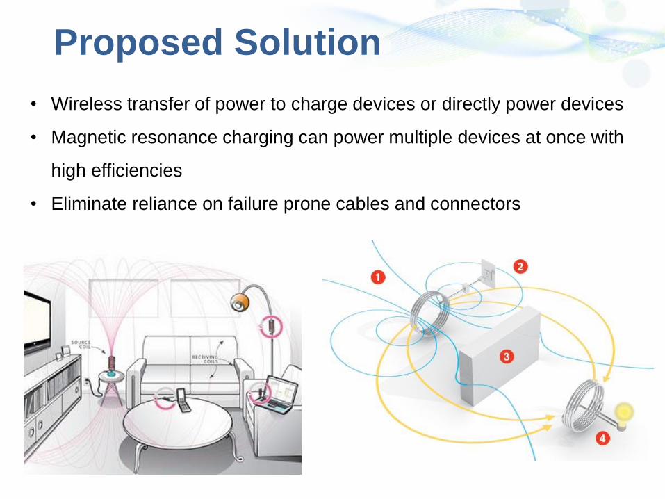
Proposed Solution
• Wireless transfer of power to charge devices or directly power devices
• Magnetic resonance charging can power multiple devices at once with
high efficiencies
• Eliminate reliance on failure prone cables and connectors
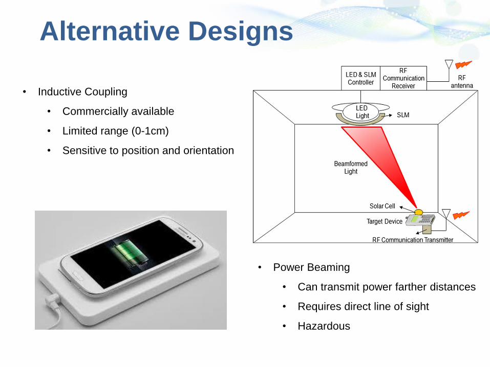
Alternative Designs
• Power Beaming
• Can transmit power farther distances
• Requires direct line of sight
• Hazardous
• Inductive Coupling
• Commercially available
• Limited range (0-1cm)
• Sensitive to position and orientation

What Already Exists
• Rezence
• Magnetic resonance wireless power standard
-Operate at 6.78 MHz
-Provide up to 50W over 5 cm
-Power up to 8 devices
• Board members include Intel, Samsung, WiTricity
• WiTricity
• Developing technical specifications
• Design and sell development kits for
commercial use.
• Demonstration kits: $1000

Societal Impacts
• Make devices more convenient – no need to plug in
• Make devices more reliable – eliminate cords and connectors
• Make devices safer – no sparking hazard, no open ports for wired
connections
• Make devices more environmentally friendly – reduce need for electro-
chemical batteries
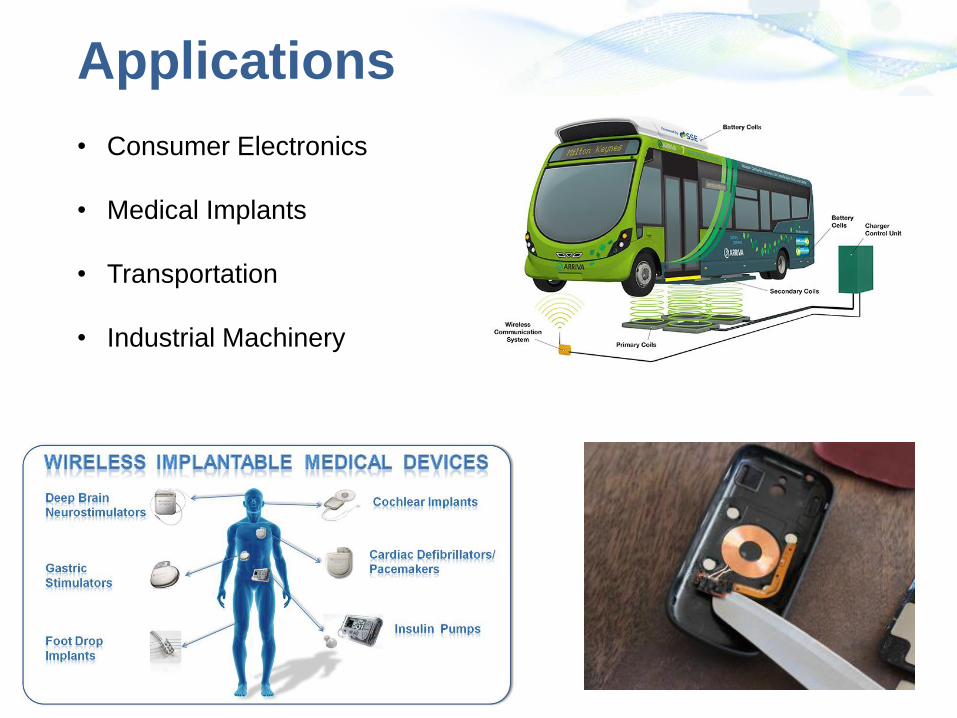
Applications
• Consumer Electronics
• Medical Implants
• Transportation
• Industrial Machinery

Our Application• Construct a charging pad and receiving
phone case to allow for resonance wireless charging in a typical home or office
• Our goal is to design a product that will make it easy for people to charge their phones without ever thinking about wires in their everyday routine
5 W over 1.5 m

Possible Problems
• Lack of communication between devices – can “steal” power
• Safety concerns over human exposure to EM waves
• Attaining a high enough efficiency to charge or power devices

Factors to Consider
• Efficiency
• Needs to be efficient in order to achieve the goal of charging a phone
• Health Concerns
• Need to meet certain standards to ensure human safety
• Power Output
• Needs to output enough power from the inductive coils in order to achieve
our goal

Efficiency and Power
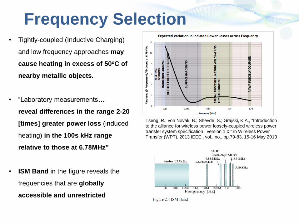
Frequency Selection• Tightly-coupled (Inductive Charging)
and low frequency approaches may
cause heating in excess of 50oC of
nearby metallic objects.
• “Laboratory measurements…
reveal differences in the range 2-20
[times] greater power loss (induced
heating) in the 100s kHz range
relative to those at 6.78MHz”
• ISM Band in the figure reveals the
frequencies that are globally
accessible and unrestricted
Tseng, R.; von Novak, B.; Shevde, S.; Grajski, K.A., "Introduction
to the alliance for wireless power loosely-coupled wireless power
transfer system specification version 1.0," in Wireless Power
Transfer (WPT), 2013 IEEE , vol., no., pp.79-83, 15-16 May 2013

Health Concerns
• The IEEE and ICNIRP recommend a localized general public SAR limit of
4 W/kg for limbs and 2 W/kg for the head and trunk in 10 g of tissue.
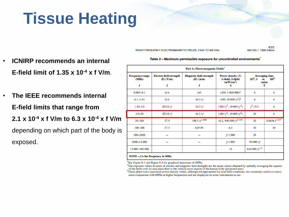
Tissue Heating
• ICNIRP recommends an internal
E-field limit of 1.35 x 10⁻⁴ x f V/m.
• The IEEE recommends internal
E-field limits that range from
2.1 x 10⁻⁴ x f V/m to 6.3 x 10⁻⁴ x f V/m
depending on which part of the body is
exposed.

Technical RequirementsInput Specifications 120 VAC at 60Hz
Frequency 13.56 MHz
Distance/Range 1.5 m
Minimum Output Power 5W
Minimum Wireless Transfer Efficiency ≥70%
Minimum Total System Efficiency ≥50%
Maximum Electric Field 60.75 V/m
Maximum Magnetic Field 1.20 A/m
Maximum Receiver Size:

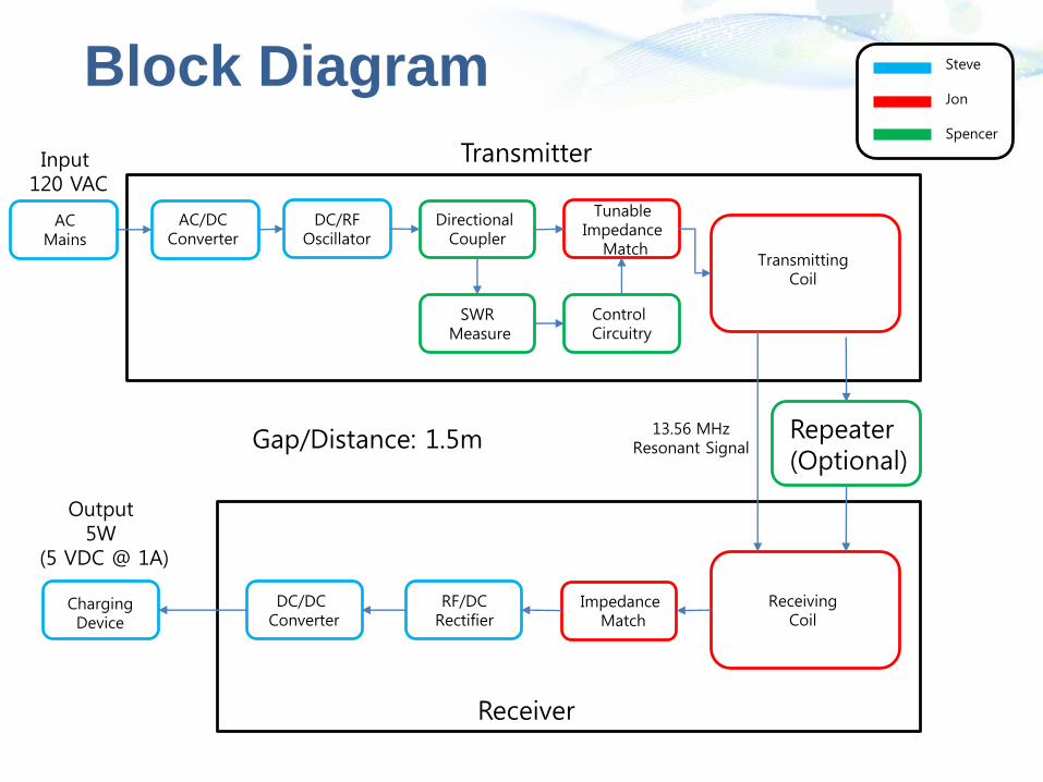
Block Diagram
Transmitter
Receiver
Repeater (Optional)
DC/RFOscillator
Directional Coupler
Tunable Impedance
Match
SWR Measure
Control Circuitry
TransmittingCoil
ReceivingCoil
RF/DCRectifier
DC/DC Converter
ChargingDevice
Impedance Match
AC/DCConverter
ACMains
Input120 VAC
Output5W
(5 VDC @ 1A)
Gap/Distance: 1.5m
Steve
Jon
Spencer
13.56 MHzResonant Signal

Tunable Impedance Matching
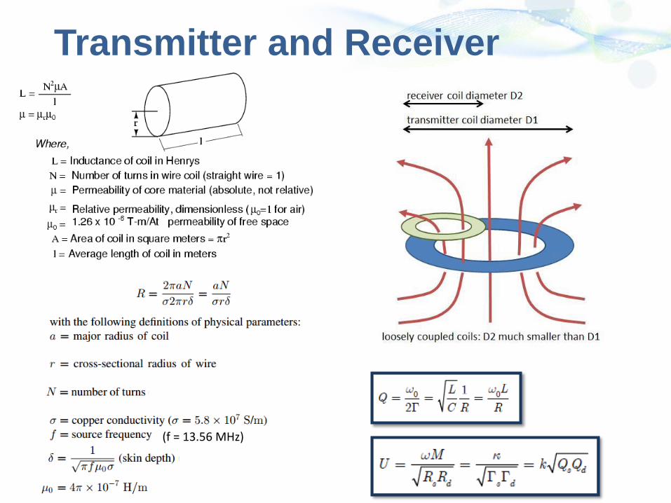
Transmitter and Receiver
(f = 13.56 MHz)
Block Diagram
Transmitter
Receiver
Repeater (Optional)
DC/RFOscillator
Directional Coupler
Tunable Impedance
Match
SWR Measure
Control Circuitry
TransmittingCoil
ReceivingCoil
RF/DCRectifier
DC/DC Converter
ChargingDevice
Impedance Match
AC/DCConverter
ACMains
Input120 VAC
Output5W
(5 VDC @ 1A)
Gap/Distance: 1.5m
Steve
Jon
Spencer
13.56 MHzResonant Signal
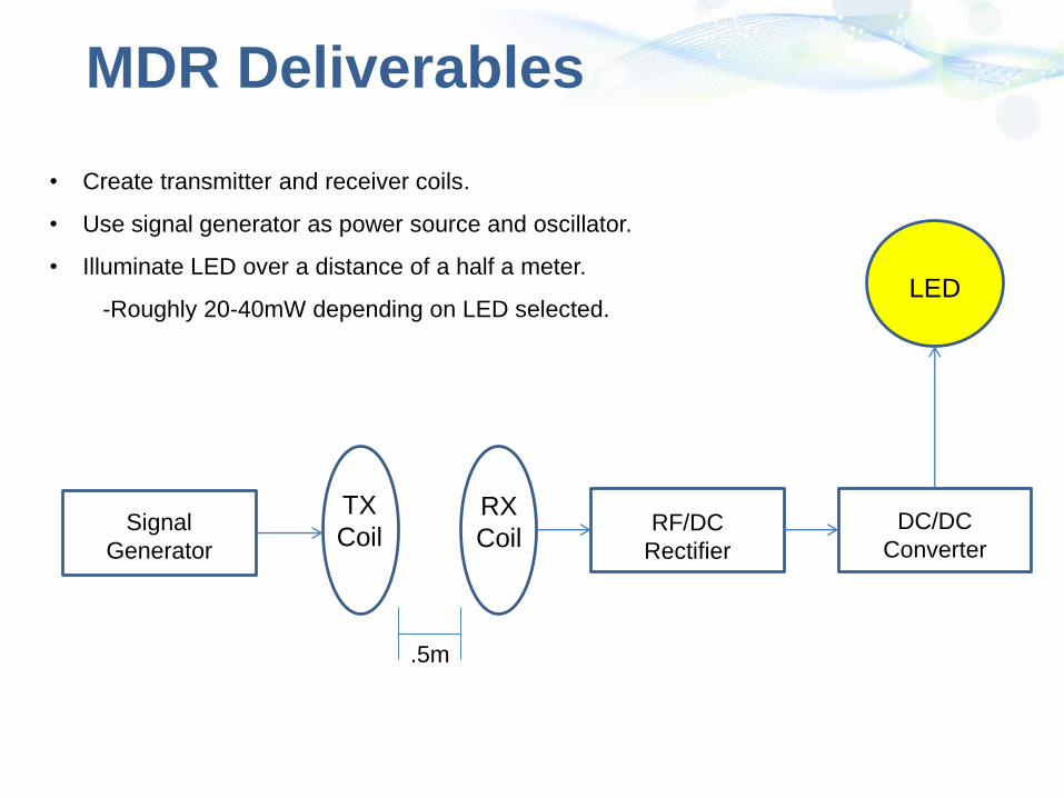
MDR Deliverables
• Create transmitter and receiver coils.
• Use signal generator as power source and oscillator.
• Illuminate LED over a distance of a half a meter.
-Roughly 20-40mW depending on LED selected.
Signal
Generator
RF/DC
Rectifier
DC/DC
Converter
TX
CoilRX
Coil
LED
.5m

Questions and Comments