
E-NOTES OF COMPUTER NETWORKS CONTENTS
26
1 E-NOTES OF COMPUTER NETWORKS CONTENTS TOPIC PAGE NO. 1. Networks Basics 1.1 Concepts of network 1 1.2 Models of network computing 2 1.3 Networking models 3 1.4 Peer-to-peer Network 4 1.5 Client server Network 4 1.6 LAN, MAN and WAN 5 1.7 Network Services 5 1.8 Topologies 6 1.9 Switching Techniques 7 2. Networking Models 2.1 OSI model: Definition, Layerd Architecture Functions of various layer 9 2.2 TCP/IP Model: Definition1, Functions of various layers 11 2.3Comparison between OSI and TCP/IP model 13 3. Network Connectivity 3.1 Network connectivity Devices 15 3.2 Hubs, Switches, Routers, Repeaters, Modem, Gateway 16 1. Concept of networking : The Concept of Networks. The generic term network refers to a group of entities (i.e. objects, people, etc.) that are connected to one another. A network, therefore, allows material or immaterial elements to be circulated among all of these entities, based on well-defined rules. Need of a Computer Network
Transcript of E-NOTES OF COMPUTER NETWORKS CONTENTS

1
E-NOTES OF COMPUTER NETWORKS
CONTENTS
TOPIC PAGE NO.
1. Networks Basics
1.1 Concepts of network 1
1.2 Models of network computing 2
1.3 Networking models 3
1.4 Peer-to-peer Network 4
1.5 Client server Network 4
1.6 LAN, MAN and WAN 5
1.7 Network Services 5
1.8 Topologies 6
1.9 Switching Techniques 7
2. Networking Models
2.1 OSI model: Definition, Layerd Architecture Functions of various layer 9
2.2 TCP/IP Model: Definition1, Functions of various layers 11
2.3Comparison between OSI and TCP/IP model 13
3. Network Connectivity
3.1 Network connectivity Devices 15
3.2 Hubs, Switches, Routers, Repeaters, Modem, Gateway 16
1. Concept of networking : The Concept of Networks. The generic term network refers
to a group of entities (i.e. objects, people, etc.) that are connected to one another. A network,
therefore, allows material or immaterial elements to be circulated among all of these entities, based
on well-defined rules.
Need of a Computer Network
2
Now the questions arises what is the need of a computer network. The need arose out of the
common economic problems. These problems are
Limited resources
A desired to share the resources
A desire to have fast and reliable communication.
1.2. Models of network computing : After you have the necessary prerequisites for
network communication, a structure must be put in place that organizes the way communication
and sharing occur. Three methods of organization, or models, are generally recognized. The three
models for network computing are as follows:
Centralized computing
Distributed computing
Collaborative or cooperative computing
1.2.1. Centralized computing
The earliest computers were large, expensive, and difficult to manage. Originally, these large
mainframe computers were not networked in the sense you are familiar with today. Jobs were
entered into the system by reading commands from card decks. The computer would execute one
job at a time and generate a printout when the job was complete. All processing still took place on
the mainframe, hence the name centralized computing. Networks, therefore, served little purpose
other than to deliver commands to and results from the powerful centralized processing device.
Large IBM and Digital (DEC) networks often still operate on this model, but Microsoft has largely
ignored it.
In summary, the centralized computing model involves the following:
All processing takes place in the central, mainframe computer.
Terminals are connected to the central computer and function only as input/output devices.
Networks may be employed to interconnect two or more mainframe computers. Terminals
connect only to the mainframe, never to each other.
This early computing model worked well in large organizations, but was not flexible and did not
scale down to meet the needs of smaller organizations. As such, new ways of sharing information
were needed to allow computing power to be shared efficiently on smaller networks.
1.2.2. Distributed Computing
As personal computers were introduced to organizations, a new model of distributed computing
emerged. Instead of concentrating computing to a central device, PCs made it possible to give each
worker an independent, individual computer. Each of these PCs can process and store data locally,
without assistance from another machine. Under the distributed computing model, networking has
evolved to enable the many distributed computers to exchange data and share resources and

3
services among themselves This server stores and retrieves files for other machines, but does not
do the thinking for these machines as a mainframe would have done in the centralized computing
model.
In summary, distributed computing involves the following:
Multiple computers are capable of operating independently.
Tasks are completed locally on various computers.
Networks enable the computers to exchange data and ser-vices but do not provide
processing assistance.
Distributed computing was a major step forward in the way that businesses could leverage their
hardware resources. However, it largely dealt with the sharing of data and printers. Processing was
left to be done at each machine separately, without any specialization or assistance.
1.3. Networking models:-
1. Peer to peer Network
2. Client server network
1.3.1. Client Server Network Model:
Client–server model is a distributed application structure that partitions tasks or workloads
between the providers of a resource or service, called servers, and service requesters, called
clients. Often clients and servers communicate over a computer network on separate
hardware, but both client and server may reside in the same system
Client : Individual workstation in a Network is client.
Server : Data are stored on powreful computer called server who provide services.

4
Fig: Client Server Network
The commonly used servers are print server, file, server, mail server and application server.
Advantages :
1. Management is proper i.e. all the data or files are placed at the same place.
2. Backup and recovery is possible in this architecture.
3. we can also access this client to server network remotely.
Disadvantage:
1. As if client send to many requests this leads to congestion in server.
2. This network is not a robust network.
3. Client toserver network is very costly and dificult ti install.
1.4.Peer to peer network:- "Peer to peer is a communication model in which each party has
the same capabilites and either party can initiatea communication session ".
In this individuals have personal machines which are equally powerful . Ever computer is called a
peer .
1.5. Client server network
Client–server model is a distributed application structure that partitions tasks or workloads
between the providers of a resource or service, called servers, and service requesters, called
clients.[1] Often clients and servers communicate over a computer network on separate hardware,
but both client and server may reside in the same system. A server host runs one or more server
programs which share their resources with clients. A client does not share any of its resources, but
5
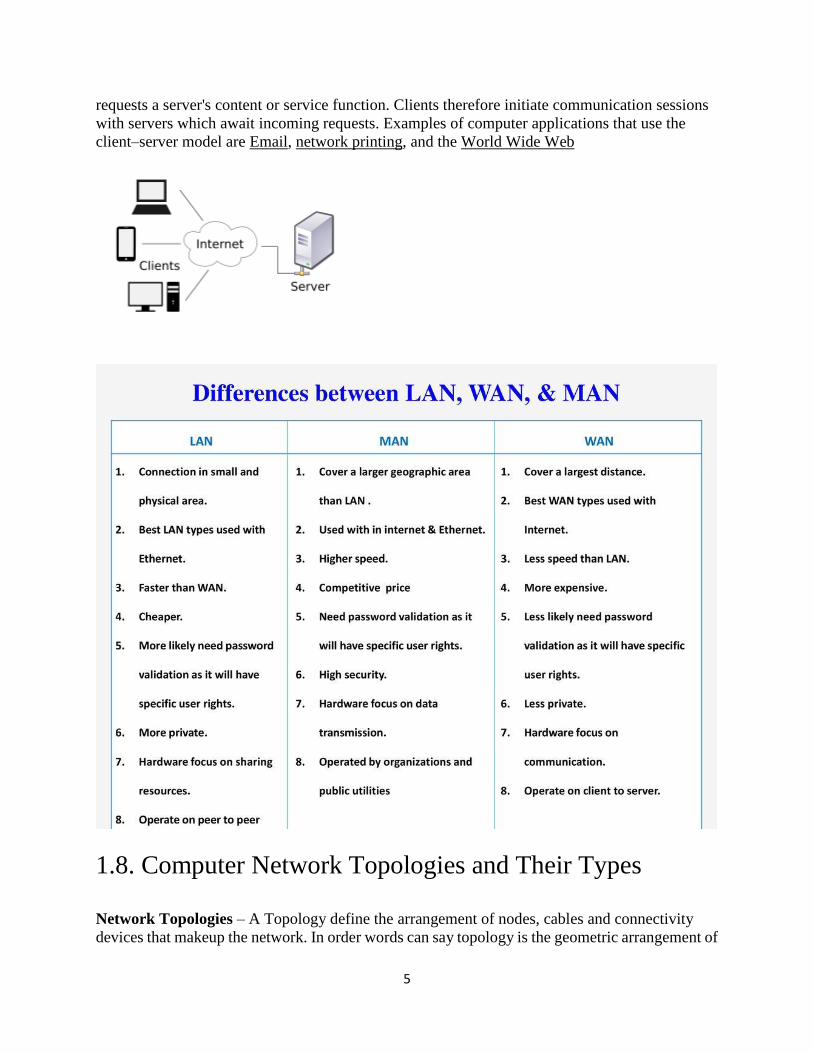
requests a server's content or service function. Clients therefore initiate communication sessions
with servers which await incoming requests. Examples of computer applications that use the
client–server model are Email, network printing, and the World Wide Web
1.8. Computer Network Topologies and Their Types
Network Topologies – A Topology define the arrangement of nodes, cables and connectivity
devices that makeup the network. In order words can say topology is the geometric arrangement of

6
workstation and the links among them. Computer Network Topologies and Their Types such as
Bus Topology ,Star Topology ,Ring Topology ,Tree Topology and Mesh Topology.
Topology can be considered as the following types –
1. Physical Topology – it describes the actual layout of the network transmission media, means the way the
network looks.
2. Logical Topology – It describes the logical pathway a single follows as it passes among the network nodes,
means the way the data passes among the nodes.
Physical & logical topologies can take several forms .The most common are:
1. Bus Topology
2. Star Topology
3. Ring Topology
4. Tree Topology
5. Mesh Topology
1. Bus Topology- If the computers are connected to one single cable then we call cable as
broadcast bus broad casting messages in done computer transmits and all other computer can
receive to the broad cast message. In a bus network the computers are connected by a cable called
a bus and messages are sent along to bus. The connected computer can receive the massage and
determine whether it in for them or not A bus network is commonly used in LAN where the data is
stored in the center computer. in a bus network the failure of a single computer does not effect the
performance of the rest of the network.
We can add a workstation to this network at any time. It is the topology used in Ethernet LAN (
CSMA /CD).
2. Star Topology- When all communication must go through a central point, we called that
topology a star topology. A star networks has a server at its center and all messages must go
through the server. When we want to send message from one computer to another, It is first send to
the server which then retract the massage to the distention computer.
The disadvantage of star network is the if the server fails the entire network doesn’t work a good
e.g. of star network is telephone switching computer in the telephone exchange which is used to
connect computers as well as telephones.

7
3. Ring Topology- In a ring network the computer devices are arranged so that the
communication connects the computer in a ring like structure. In this structure any computer can
communication with any other computer by sending a signal around the ring. Each message
consists of its distension address and the data to be transmitted as the message proceeds around the
ring each computer determines whether it is the recipient of the message .if it is not the message is
send to the next computer. Each station takes an active role in transferring the message. It a single
computer fails at least a portion of the network. Will not work.
4. Tree Topology- The tree topology – also called a “hierarchical “or “star of stars” topology, tree
topology is a combination of bus and star topologies. Nodes are connected in groups of star
configured workstation that branch out from a single “root”. The root node usually controls the
network and sometimes network traffic flow. This topology is easy to extend when new users need
to be added, it is simply a matter of adding a new hub. It also is easy to control because the root
provides centralized management and monitoring.
The principal disadvantage is obvious when the entire network depends on one node, failure of that
node will bring the whole network down.

8
5. Mesh Topology- Every device has a dedicated point to point link to every other device.
Dedicated means that the link carries traffic only between the two devices it connects. Mesh
topology is really a hybrid model representing an all channel topology. A fully Connected mesh
network therefore has n(n-1)/2 physical channels to link n devices. Every device on the network
must have n-1 input/output ports.
The advantage of mesh topology it has very much fault tolerance capacity. In case of a media
failure the single can be bypassed through the other routers. Dedicated links guarantees that each
connection can carry its own data load, thus eliminating the traffic problems. It is privacy or
security is very high.
The disadvantage is installation and reconfiguration is very difficult. It is the most expensive
network.
9
2. NETWORK MODELS
OSI Model:-
The Open Systems Interconnection model (OSI model) is a conceptual model that characterizes
and standardizes the communication functions of a telecommunication or computing system
without regard to its underlying internal structure and technology. Its goal is the interoperability of
diverse communication systems with standard communication protocols. The model partitions a
communication system into abstraction layers. The original version of the model had seven layers.
Definitions
Communication protocols enable an entity in one host to interact with a corresponding entity at the
same layer in another host. Service definitions, like the OSI Model, abstractly describe the
functionality provided to an (N)-layer by an (N-1) layer, where N is one of the seven layers of
protocols operating in the local host.
There are 7 layers in OSI model
Layer 1: Physical Layer
The physical layer is responsible for the transmission and reception of unstructured raw data
between a device and a physical transmission medium. It converts the digital bits into electrical,
radio, or optical signals. Layer specifications define characteristics such as voltage levels, the
timing of voltage changes, physical data rates, maximum transmission distances, modulation
scheme, channel access method and physical connectors
Layer 2: Data Link Layer
The data link layer provides node-to-node data transfer—a link between two directly connected
nodes. It detects and possibly corrects errors that may occur in the physical layer. It defines the
protocol to establish and terminate a connection between two physically connected devices. It also
defines the protocol for flow control between them
Layer 3: Network Layer
The network layer provides the functional and procedural means of transferring variable length
data sequences (called packets) from one node to another connected in "different networks". A
network is a medium to which many nodes can be connected, on which every node has an address
and which permits nodes connected to it to transfer messages to other nodes connected to it by
merely providing the content of a message and the address of the destination node and letting the

10
network find the way to deliver the message to the destination node, possibly routing it through
intermediate nodes. If the message is too large to be transmitted from one node to another on the
data link layer between those nodes, the network may implement message delivery by splitting the
message into several fragments at one node, sending the fragments independently, and
reassembling the fragments at another node. It may, but does not need to, report delivery errors
Layer 4: Transport Layer
The transport layer provides the functional and procedural means of transferring variable-length
data sequences from a source to a destination host, while maintaining the quality of service
functions.
The transport layer controls the reliability of a given link through flow control,
segmentation/desegmentation, and error control. Some protocols are state- and
connection-oriented. This means that the transport layer can keep track of the segments and
re-transmit those that fail delivery. The transport layer also provides the acknowledgement of the
successful data transmission and sends the next data if no errors occurred. The transport layer
creates segments out of the message received from the application layer. Segmentation is the
process of dividing a long message into smaller messages.
,
Layer 5: Session Layer
The session layer controls the dialogues (connections) between computers. It establishes, manages
and terminates the connections between the local and remote application. It provides for
full-duplex, half-duplex, or simplex operation, and establishes procedures for checkpointing,
suspending, restarting, and terminating a session. In the OSI model, this layer is responsible for
gracefully closing a session, which is handled in the Transmission Control Protocol at the transport
layer in the Internet Protocol Suite. This layer is also responsible for session checkpointing and
recovery, which is not usually used in the Internet Protocol Suite. The session layer is commonly
implemented explicitly in application environments that use remote procedure calls.
Layer 6: Presentation Layer
The presentation layer establishes context between application-layer entities, in which the
application-layer entities may use different syntax and semantics if the presentation service
provides a mapping between them. If a mapping is available, presentation protocol data units are
encapsulated into session protocol data units and passed down the protocol stack.
This layer provides independence from data representation by translating between application and
network formats. The presentation layer transforms data into the form that the application accepts.
This layer formats data to be sent across a network. It is sometimes called the syntax layer.[9] The
presentation layer can include compression functions.[10] The Presentation Layer negotiates the
Transfer Syntax.
11
The original presentation structure used the Basic Encoding Rules of Abstract Syntax Notation
One (ASN.1), with capabilities such as converting an EBCDIC-coded text file to an ASCII-coded
file, or serialization of objects and other data structures from and to XML. ASN.1 effectively
makes an application protocol invariant with respect to syntax.
Layer 7: Application Layer
The application layer is the OSI layer closest to the end user, which means both the OSI
application layer and the user interact directly with the software application. This layer interacts
with software applications that implement a communicating component. Such application
programs fall outside the scope of the OSI model. Application-layer functions typically include
identifying communication partners, determining resource availability, and synchronizing
communication. When identifying communication partners, the application layer determines the
identity and availability of communication partners for an application with data to transmit. The
most important distinction in the application layer is the distinction between the application-entity
and the application. For example, a reservation website might have two application-entities: one
using HTTP to communicate with its users, and one for a remote database protocol to record
reservations. Neither of these protocols have anything to do with reservations. That logic is in the
application itself. The application layer per se has no means to determine the availability of
resources in the network.
TCP/IP Model:-
The TCP/IP model is a concise version of the OSI model. It contains four layers, unlike seven
layers in the OSI model. The layers are:
1. Process/Application Layer
2. Host-to-Host/Transport Layer
3. Internet Layer
4. Network Access/Link Layer The first layer is the Process layer on the behalf of the sender and Network Access layer on the behalf of the
receiver. During this article, we will be talking on the behalf of the receiver.
1. Network Access Layer –
This layer corresponds to the combination of Data Link Layer and Physical Layer of the OSI model. It looks
out for hardware addressing and the protocols present in this layer allows for the physical transmission of
data.
We just talked about ARP being a protocol of Internet layer, but there is a conflict about declaring it as a
protocol of Internet Layer or Network access layer. It is described as residing in layer 3, being encapsulated
by layer 2 protocols.
2. Internet Layer –

12
This layer parallels the functions of OSI’s Network layer. It defines the protocols which are responsible for
logical transmission of data over the entire network. The main protocols residing at this layer are :
1. IP – stands for Internet Protocol and it is responsible for delivering packets from the source host to
the destination host by looking at the IP addresses in the packet headers. IP has 2 versions:
IPv4 and IPv6. IPv4 is the one that most of the websites are using currently. But IPv6 is growing as
the number of IPv4 addresses are limited in number when compared to the number of users.
2. ICMP – stands for Internet Control Message Protocol. It is encapsulated within IP datagrams and is
responsible for providing hosts with information about network problems.
3. ARP – stands for Address Resolution Protocol. Its job is to find the hardware address of a host from
a known IP address. ARP has several types: Reverse ARP, Proxy ARP, Gratuitous ARP and Inverse
ARP.
3. Host-to-Host Layer –
This layer is analogous to the transport layer of the OSI model. It is responsible for end-to-end
communication and error-free delivery of data. It shields the upper-layer applications from the complexities
of data. The two main protocols present in this layer are :
1. Transmission Control Protocol (TCP) – It is known to provide reliable and error-free
communication between end systems. It performs sequencing and segmentation of data. It also has
acknowledgment feature and controls the flow of the data through flow control mechanism. It is a
very effective protocol but has a lot of overhead due to such features. Increased overhead leads to
increased cost.
2. User Datagram Protocol (UDP) – On the other hand does not provide any such features. It is the
go-to protocol if your application does not require reliable transport as it is very cost-effective. Unlike
TCP, which is connection-oriented protocol, UDP is connectionless.
4. Process Layer –
This layer performs the functions of top three layers of the OSI model: Application, Presentation and
Session Layer. It is responsible for node-to-node communication and controls user-interface specifications.
Some of the protocols present in this layer are: HTTP, HTTPS, FTP, TFTP, Telnet, SSH, SMTP, SNMP,
NTP, DNS, DHCP, NFS, X Window, LPD. Have a look at Protocols in Application Layer for some
information about these protocols. Protocols other than those present in the linked article are :
1. HTTP and HTTPS – HTTP stands for Hypertext transfer protocol. It is used by the World Wide
Web to manage communications between web browsers and servers. HTTPS stands for
HTTP-Secure. It is a combination of HTTP with SSL(Secure Socket Layer). It is efficient in cases
where the browser need to fill out forms, sign in, authenticate and carry out bank transactions.
2. SSH – SSH stands for Secure Shell. It is a terminal emulations software similar to Telnet. The reason
SSH is more preferred is because of its ability to maintain the encrypted connection. It sets up a
secure session over a TCP/IP connection.
3. NTP – NTP stands for Network Time Protocol. It is used to synchronize the clocks on our computer
to one standard time source. It is very useful in situations like bank transactions. Assume the
following situation without the presence of NTP. Suppose you carry out a transaction, where your
computer reads the time at 2:30 PM while the server records it at 2:28 PM. The server can crash very
badly if it’s out of sync.

13
This article is contributed by Achiv Chauhan and Palak Jain. If you like GeeksforGeeks and would like to
contribute, you can also write an article using contribute.geeksforgeeks.org or mail your article to
[email protected]. See your article appearing on the GeeksforGeeks main page and help other
Geeks.
Please write comments if you find anything incorrect, or you want to share more information about the topic
discussed above.
Difference between OSI and TCP/IP Reference Model
Following are some major differences between OSI Reference Model and TCP/IP Reference Model, with
diagrammatic comparison below.
OSI(Open System Interconnection)
TCP/IP(Tra
nsmission
Control
Protocol /
Internet
Protocol)
1. OSI is a generic, protocol independent standard, acting as a communication gateway
between the network and end user.
1.TCP/IP
model is
based on
standard
protocols
around
which the
Internet has
developed. It
is a
communicati
on protocol,
which allows
connection
of hosts over
a network.
2. In OSI model the transport layer guarantees the delivery of packets.
2. In TCP/IP
model the
transport
layer does
not

14
guarantees
delivery of
packets. Still
the TCP/IP
model is
more
reliable.
3. Follows vertical approach.
3. Follows
horizontal
approach.
4. OSI model has a separate Presentation layer and Session layer.
4. TCP/IP
does not
have a
separate
Presentation
layer or
Session
layer.
5. Transport Layer is Connection Oriented.
5. Transport
Layer is both
Connection
Oriented and
Connection
less.
6. Network Layer is both Connection Oriented and Connection less.
6. Network
Layer is
Connection
less.
7. OSI is a reference model around which the networks are built. Generally it is used as a guidance
tool.
7. TCP/IP
model is, in a
way
implementati
on of the OSI
model.
8. Network layer of OSI model provides both connection oriented and connectionless service.
8. The
Network
layer in
TCP/IP
model

15
provides
connectionle
ss service.
9. OSI model has a problem of fitting the protocols into the model.
9. TCP/IP
model does
not fit any
protocol
10. Protocols are hidden in OSI model and are easily replaced as the technology changes.
10. In
TCP/IP
replacing
protocol is
not easy.
11. OSI model defines services, interfaces and protocols very clearly and makes clear distinction
between them. It is protocol independent.
11. In
TCP/IP,
services,
interfaces
and
protocols are
not clearly
separated. It
is also
protocol
dependent.
12. It has 7 layers
NETWORK CONNECTIVITY:-
Network Connectivity Devices:-
1.4 Common Network Connectivity Devices:
1.5. WAN Devices
The connectivity devices are:
o The Network Interface card (NIC) o The hub
12. It has 4
layers

16
o The switch o The bridge o Transceivers o Wireless access points o The router o The gateway
Network Interface Card (NIC):
The Network Interface Card (NIC) used connect the computer to the external network. It will normally
have a PCI connector (Edge connector) to connect to one of the PC expansion slots, and an RJ-45
connector to connect to external Ethernet. Note that the interface connectors may differ depending upon
the expansion bus being used (for example, PCI, ISA, EISA, USB etc.), and the networking media being
used (for example, 10Base2, 10Base5, 10BaseT, etc.). Each of these have their own interface
specifications. Almost all NICs have LED indicators showing the network connectivity.
A commonly used Network Interface Card is shown in the figure below.
Network Interface Card Model
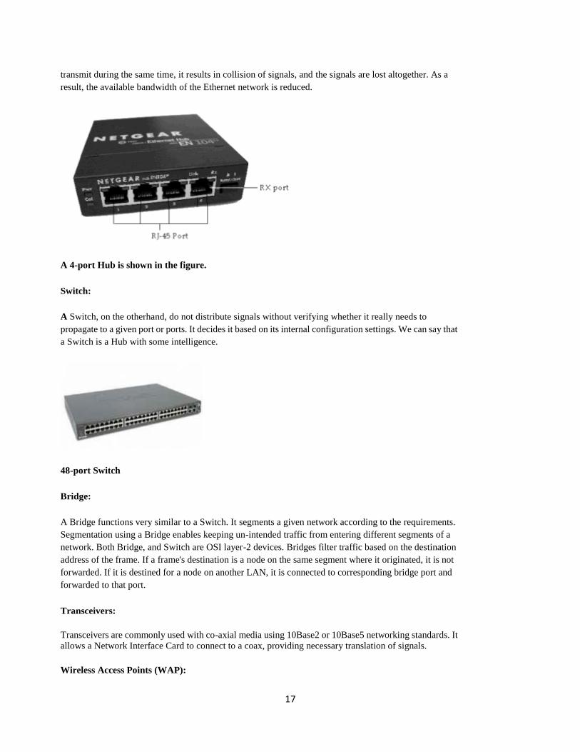
Hub:
A Hub connects all the nodes of a network using Twisted Pair (UTP or STP) cables. In a Hub, the signals
received on one port are transmitted to all other ports, and vice versa. All nodes (work stations) connected
using a Hub can listen to one another all the time. The advantage of using a Hub is low cost, and easy
integration. The disadvantage is reduced bandwidth, and data security. The reduction in bandwidth comes
due to the fact that all workstations are in the same collision domain. If two or more workstations try to
17
transmit during the same time, it results in collision of signals, and the signals are lost altogether. As a
result, the available bandwidth of the Ethernet network is reduced.
A 4-port Hub is shown in the figure.
Switch:
A Switch, on the otherhand, do not distribute signals without verifying whether it really needs to
propagate to a given port or ports. It decides it based on its internal configuration settings. We can say that
a Switch is a Hub with some intelligence.
48-port Switch
Bridge:
A Bridge functions very similar to a Switch. It segments a given network according to the requirements.
Segmentation using a Bridge enables keeping un-intended traffic from entering different segments of a
network. Both Bridge, and Switch are OSI layer-2 devices. Bridges filter traffic based on the destination
address of the frame. If a frame's destination is a node on the same segment where it originated, it is not
forwarded. If it is destined for a node on another LAN, it is connected to corresponding bridge port and
forwarded to that port.
Transceivers:
Transceivers are commonly used with co-axial media using 10Base2 or 10Base5 networking standards. It
allows a Network Interface Card to connect to a coax, providing necessary translation of signals.
Wireless Access Points (WAP):

18
A wireless access point allows mobile users to connect to a central network node without using any wires
. Wireless connectivity is useful for mobile workstations, since there is no wiring involved. The wireless
access standards are broadly divided into 802.11a, 802.11b, and 802.11g. 802.11g is most popular among
these due to high bandwidth that it provides, and the availability of hardware. A commercially available
wireless access point is shown in the figure below.
A WAP device Back-panel
Router:
A Router connects multiple networks, and uses routing to forward packets. It is a OSI Layer-3 device and
works on the logical address of a host or a node. Compare this with a Switch which works on the physical
address (such as MAC address) of a host or a node. A simple DSL router is shown in the figure below.
Router
19
Gateways:
Gateways are the most complex devices with respect to the functionality. They typically work at the upper
most layers of OSI model. A gateway is used to connect two different environments, such as a
Frame-Relay network and an X.25 network.
1.5 WAN devices:
Other network connectivity devices that may be not directly participating in moving network data are:
Modems ISDN terminal adapters CSU/DSU
Modems:
The Term Modem is the acronym of Modulator/DEModulator. There are several types of modems. These
include:
Dial-up Analog Modem Broadband Modem
Analog modems are widely used to connect to the Internet using normal telephone lines. These modems
use the same frequencies used for voice transmission. Therefore, you can not make a call or receive a call
(voice call) when using this modem to connect to the Internet.
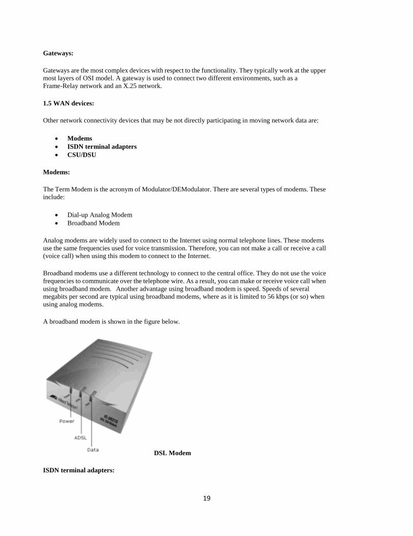
Broadband modems use a different technology to connect to the central office. They do not use the voice
frequencies to communicate over the telephone wire. As a result, you can make or receive voice call when
using broadband modem. Another advantage using broadband modem is speed. Speeds of several
megabits per second are typical using broadband modems, where as it is limited to 56 kbps (or so) when
using analog modems.
A broadband modem is shown in the figure below.
DSL Modem
ISDN terminal adapters:

20
ISDN is short for Integrated Service Digital Network (ISDN). It delivers digital services over
conventional telephone wires. You can connect your phone to an ISDN line using a terminal adapter (TA).
An ISDN modem provides higher speeds compared to analog modems, but far less speed when compared
to broadband modems.
CSU/DSU:
CSU/DSU stands for Channel Service Unit/Data Service Unit. These are commonly used for leased lines
from Telcos. The CSU terminates the line at the customer’s side. The DSU does the transmission of signal
through the CSU.
Definition of hub
Hub
There are two primary types of hubs in the computing world: 1) network hubs
and 2) USB hubs.
1. Network hub
A network hub is a device that allows multiple computers to communicate with each
other over a network. It has several Ethernet ports that are used to connect two or
more network devices together. Each computer or device connected to the hub can
communicate with any other device connected to one of the hub's Ethernet ports.
2. USB hub
A USB hub is a device that allows multiple peripherals to connect through a single
USB port. It is designed to increase the number of USB devices you can connect to a
computer. For example, if your computer has two USB ports, but you want to
connect five USB devices, you can connect a 4-port USB hub to one of the ports. The
hub will create four ports out of one, giving you five total ports. The USB interface
allows you to daisy chain USB hubs together and connect up to 127 devices to a

21
single computer.
Router
This is a hardware device that routes data (hence the name) from a local area network
(LAN) to another network connection. A router acts like a coin sorting machine,
allowing only authorized machines to connect to other computer systems. Most
routers also keep log files about the local network activity.
While repeaters all serve the same purpose, they come in many forms. Some wireless
devices, often called "range extenders" are designed to be used specifically as
repeaters. Other devices, such as hubs, switches, and routers can all be configured as
repeaters using a software utility or web interface that controls the wireless device.
NOTE: Since repeaters only relay an incoming signal, using a router as a repeater
does not make use of its signal routing capability. Therefore, it make more sense to
use a range extender as a repeater if possible.
Fig:- ROUTER
Modem

22
Modem is short for "Modulator / Demodulator." It is a hardware component that
allows a computer or other device, such as a router or switch, to connect to the
Internet. It converts or "modulates" an analog signal from a telephone or cable wire
to a digital signal that a computer can recognize. Similarly, it converts outgoing
digital data from a computer or other device to an analog signal.
NOTE: Since a modem converts analog signals to digital and vice versa, it may be
considered an ADC or DAC. Modems are not needed for fiber optic connections
because the signals are transmitted digitally from beginning to end.
Fig:- MODEM
Gateway
A gateway is a hardware device that acts as a "gate" between two networks. It may
be a router, firewall, server, or other device that enables traffic to flow in and out of
the network.
While a gateway protects the nodes within network, it also a node itself. The
gateway node is considered to be on the "edge" of the network as all data must flow
through it before coming in or going out of the network. It may also translate data
received from outside networks into a format or protocol recognized by devices
within the internal network.
NOTE: Gateway is also the name of a computer hardware company founded in the
United States in 1985. The company was acquired by Acer in 2007 but still sells
computers under the Gateway name.

24

25

26