E N G I N E E R I N G D A T A January 2010 Supersedes ...
36
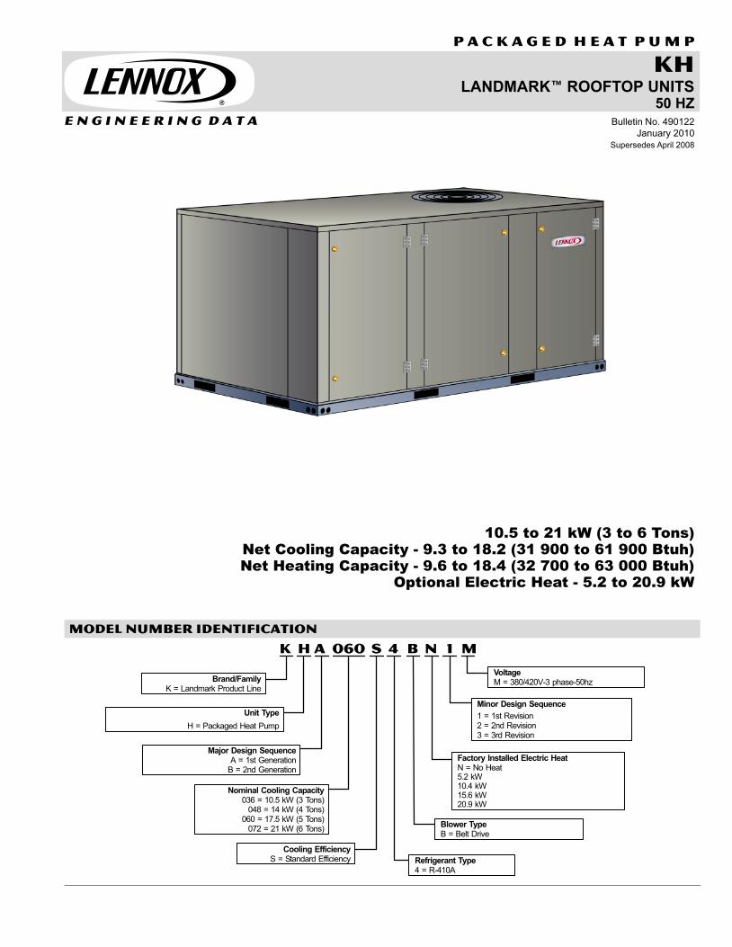
E N G I N E E R I N G D A T A KH LANDMARKE ROOFTOP UNITS 50 HZ P A C K A G E D H E A T P U M P Bulletin No. 490122 January 2010 Supersedes April 2008 10.5 to 21 kW (3 to 6 Tons) Net Cooling Capacity - 9.3 to 18.2 (31 900 to 61 900 Btuh) Net Heating Capacity - 9.6 to 18.4 (32 700 to 63 000 Btuh) Optional Electric Heat - 5.2 to 20.9 kW MODEL NUMBER IDENTIFICATION KhA M 1 060 S N 4 B Major Design Sequence A = 1st Generation B = 2nd Generation Brand/Family K = Landmark Product Line Unit Type H = Packaged Heat Pump Nominal Cooling Capacity 036 = 10.5 kW (3 Tons) 048 = 14 kW (4 Tons) 060 = 17.5 kW (5 Tons) 072 = 21 kW (6 Tons) Cooling Efficiency S = Standard Efficiency Minor Design Sequence 1 = 1st Revision 2 = 2nd Revision 3 = 3rd Revision Voltage M = 380/420V−3 phase−50hz Factory Installed Electric Heat N = No Heat 5.2 kW 10.4 kW 15.6 kW 20.9 kW Refrigerant Type 4 = R−410A Blower Type B = Belt Drive
Transcript of E N G I N E E R I N G D A T A January 2010 Supersedes ...
E N G I N E E R I N G D A T A
KHLANDMARK� ROOFTOP UNITS
50 HZ
P A C K A G E D H E A T P U M P
Bulletin No. 490122
January 2010
Supersedes April 2008
10.5 to 21 kW (3 to 6 Tons)Net Cooling Capacity − 9.3 to 18.2 (31 900 to 61 900 Btuh)Net Heating Capacity − 9.6 to 18.4 (32 700 to 63 000 Btuh)
Optional Electric Heat − 5.2 to 20.9 kW
MODEL NUMBER IDENTIFICATION
K h A M1060 S N4 B
Major Design SequenceA = 1st Generation
B = 2nd Generation
Brand/FamilyK = Landmark Product Line
Unit Type
H = Packaged Heat Pump
Nominal Cooling Capacity036 = 10.5 kW (3 Tons)
048 = 14 kW (4 Tons)060 = 17.5 kW (5 Tons)
072 = 21 kW (6 Tons)
Cooling EfficiencyS = Standard Efficiency
Minor Design Sequence
1 = 1st Revision2 = 2nd Revision3 = 3rd Revision
VoltageM = 380/420V−3 phase−50hz
Factory Installed Electric HeatN = No Heat5.2 kW10.4 kW15.6 kW20.9 kW
Refrigerant Type4 = R−410A
Blower TypeB = Belt Drive
Landmark® Packaged Heat Pump 10.5 to 21 kW (3 to 6 Ton) 50hz / Page 2
CONTENTS
Accessory Air Resistance Page 19. . . . . . . . . . . . . . . . . . . . . . . . . . . . . . . . .
Blower Performance Pages 11−18. . . . . . . . . . . . . . . . . . . . . . . . . . . . . . . . . .
Cooling/Heating Ratings Pages 9. . . . . . . . . . . . . . . . . . . . . . . . . . . . . . . . . .
Dimensions Pages 25−32. . . . . . . . . . . . . . . . . . . . . . . . . . . . . . . . . . . . . . . . .
Electrical/Electric Heat Data Page 21. . . . . . . . . . . . . . . . . . . . . . . . . . . . . . .
Features and Benefits Pages 2−4. . . . . . . . . . . . . . . . . . . . . . . . . . . . . . . . . .
Installation Clearances Page 22. . . . . . . . . . . . . . . . . . . . . . . . . . . . . . . . . . . .
Model Number Identification Page 1. . . . . . . . . . . . . . . . . . . . . . . . . . . . . . . .
Options / Accessories Pages 5−7. . . . . . . . . . . . . . . . . . . . . . . . . . . . . . . . . .
Specifications Pages 8. . . . . . . . . . . . . . . . . . . . . . . . . . . . . . . . . . . . . . . . . . .
Sound Data Page 22. . . . . . . . . . . . . . . . . . . . . . . . . . . . . . . . . . . . . . . . . . . . .
Temperature Control Systems Page 23. . . . . . . . . . . . . . . . . . . . . . . . . . . . .
Weights Page 24. . . . . . . . . . . . . . . . . . . . . . . . . . . . . . . . . . . . . . . . . . . . . . . . .
FEATURES AND BENEFITS
TESTING
Components bonded for grounding to
meet safety standards for servicing
required by Underwriters Laboratories
(UL) and the International
Electrotechnical Commission (IEC).
10.5 thru 17.6 kW models cooling
performance is rated at test conditions
included in Air−Conditioning, Heating
and Refrigeration Institute (AHRI)
Standard 210/240−2008 while operating
at rated voltage and air volumes.
21 kW models cooling performance is
rated at test conditions included in
Air−Conditioning, Heating and
Refrigeration Institute (AHRI) Standard
340/360−2007 while operating at rated
voltage and air volumes.
International Organization for
Standardization (ISO) 9001 Registered
Manufacturing Quality System.
CABINET
Construction
Heavy−gauge steel panels and full
perimeter heavy−gauge galvanized
steel base rail provides structural
integrity for transportation, handling,
and installation.
Base rails have rigging holes. Three
sides of the base rail have fork slots.
Raised edges around duct and power
entry openings in the bottom of the unit
provide additional protection against
water entering the building.
Air−Flow Choice
Units are shipped in downflow (vertical)
configuration, can be field converted to
horizontal air flow configuration without
the need of a kit.
Power Entry
Electrical lines can be brought through
the unit base or through horizontal
access knock−outs.
Exterior Panels
Constructed of heavy−gauge,
galvanized steel with a two−layer
enamel paint finish.
Insulation
All panels adjacent to conditioned air are
fully insulated with non−hygroscopic
fiberglass insulation.
Unit base is fully insulated. The
insulation also serves as an air seal to
the roof curb, eliminating the need to
add a seal during installation.
Access Panels
Access panels are provided for the
economizer/filter section,
heating/blower section, and the
compressor/controls section.
OPTIONS/ACCESSORIES
Factory Installed
Corrosion Protection
A completely flexible immersed coatingwith an electrodeposited dry filmprocess. (AST ElectroFin E−Coat)Meets Mil Spec MIL−P−53084, ASTMB117 Standard Method Salt SprayTesting, ASTM 1153 StandardSpecification for Methyl Isobutyl Ketone.
Hinged Access Panels
Large access panels are hinged and
have quarter−turn, latching handles for
quick and easy access to maintenance
areas (economizer / filter, compressor /
controls, heating / blower).
Field Installed
Coil Guards
Painted, galvanized steel wire guards to
protect outdoor coil. Not used with Hail
Guards.
Hail Guards
Constructed of heavy gauge steel,
painted to match cabinet, helps protect
outdoor coils from hail damage. Not
used with Coil Guards.
B
C
D
E
F

Landmark® Packaged Heat Pump 10.5 to 21 kW (3 to 6 Ton) 50hz / Page 3
FEATURES AND BENEFITS
B
C
D
E
F
G
H
J
I
K
M
KHA060S(Heat Pump)
Shown With Optional Economizer, Power Exhaust andHinged Access Panels
L
N
COOLING / HEATINGSYSTEM
Designed to maximize sensible and
latent cooling performance at design
conditions.
System can operate in the cooling mode
from −1°C to 52°C without any additional
controls.
R−410A RefrigerantNon−chlorinebased, ozonefriendly, R−410A.Unit is factory pre−charged withrefrigerant. See Specifications Tables.
Compressor
Resiliently mounted on rubber
grommets for quiet operation.
Copeland Scroll� compressors for
high performance, reliability and quiet
operation.
Compressor Crankcase Heater
Protects against refrigerant migration
that can occur during low ambient
operation.
High Pressure Switch
Protects the compressor from overload
conditions such as dirty condenser
coils, blocked refrigerant flow, or loss of
outdoor fan operation.
Check/Thermal Expansion Valves
Assures optimal performance
throughout the application range.
Removable element head.
Reversing Valves
4-way interchange reversing valve
effects a rapid change in direction of
refrigerant flow resulting in quick
changeover from cooling to heating and
vice versa.
Defrost Control
Provides a defrost cycle, if needed, every
30 or 60 or 90 minutes (adjustable) of
compressor �on" time at outdoor coil
temperature below 2°C. Temperature
switch mounted on outdoor coil liquid line
terminates defrost cycle.
Filter/Drier
High capacity filter/drier protects the
system from dirt and moisture.
Freezestat
Protects the evaporator coil from
damaging ice build−up due to conditions
such as low/no air flow, or low refrigerant
charge.
Coil Construction
Copper tube construction, enhanced
rippled−edge aluminum fins, flared
shoulder tubing connections, silver
soldered construction for improved heat
transfer. Factory leak tested.
Indoor Coil
Cross row circuiting with rifled copper
tubing optimizes both sensible and
latent cooling capacity.
Outdoor Coil
Two independent formed coils allow
separation for cleaning.
Condensate Drain Pan
Plastic pan, sloped to meet drainage
requirements of American Society of
Heating Refrigeration and Air
Conditioning Engineers 62.1.
Side or bottom drain connections.
Reversible to allow connection at back
of unit.
Outdoor Coil Fan Motor
Thermal overload protected, totally
enclosed, permanently lubricated
sleeve (036 and 048 models) or ball
bearings (060 and 072 models), shaft
up, wire basket mount.
Outdoor Coil Fan
Polyvinyl chloride (PVC) coated fan
guard furnished.
REQUIRED SELECTIONS
Cooling Capacity
Specify nominal cooling capacity of the
unit.
OPTIONS/ACCESSORIES
Field Installed
Condensate Drain Trap
Field installed only.
Available in copper or polyvinyl chloride
(PVC).
Low Ambient Kit
Cycles the outdoor fan while allowing
compressor operation in the cooling
cycle. This intermittent fan operation
allows the system to operate without
icing the evaporator coil and losing
capacity. Designed for use in ambient
temperatures no lower than −18°C.
G
H
I
J
K
Landmark® Packaged Heat Pump 10.5 to 21 kW (3 to 6 Ton) 50hz / Page 4
FEATURES AND BENEFITS
CONTROLS
Unit Control
All control voltage is provided via a 24V
(secondary) transformer with built−in
circuit breaker protection.
Heat/Cool Staging − Capable of up to 2
heat / 2 cool staging with a third party
DDC control system or thermostat.
Low Voltage Terminal Block −
Provides screw terminal connections
for thermostat or controller wiring.
Night Setback Mode − Saves energy
by closing outdoor air dampers and
operating supply fan on thermostat
demand only.
OPTIONS / ACCESSORIESField Installed
Dirty Filter Switch
Senses static pressure increase
indicating dirty filter condition.
Smoke Detector
Photoelectric type, installed in supply air
section, return air section or both
sections. Available with power board
and single sensor (supply or return) or
power board and two sensors (supply
and return). Power board located in unit
control compartment.
Thermostats
Control system and thermostat options.
Aftermarket unit controller options. See
Page 23.
BLOWER
A wide selection of supply air blower
options are available to meet a variety of
air flow requirements.
Motor
Equipped with ball bearings.
External overload protector.
Belt drive motors are offered on all
models.
Supply Air Blower
Forward curved blades, blower wheel is
statically and dynamically balanced.
All belt drive motors have adjustable
pulley for speed change.
Ordering Information
Specify drive kit number when base unit
is ordered.
REQUIRED SELECTIONS
Supply Air Blower
Order one drive kit (See Blower Data
Table for specifications)
AIR FILTERS
Disposable 51 mm filters furnished as
standard.
OPTIONS/ACCESSORIES
Field Installed
Healthy Climate® UVC Germicidal
Lamps
Helps eliminate mold and bacterial
growth on the evaporator and drain
pans. Improves indoor air quality and
maintains efficiency of system by
reducing fouling of evaporator coil.
Indoor Air Quality (CO2) Sensor
Monitors CO2 levels adjusts
economizer dampers as needed for
Demand Control Ventilation.
ELECTRICAL
OPTIONS/ACCESSORIES
Field Installed
Electric Heat
Helix wound nichrome elements,individual element limit controls, wiringharness. Unit fuse block furnished asstandard.
SERVICEABILITY
Designed to streamline general
maintenance and decrease
troubleshooting time.
Marked & Color−Coded Wiring
All electrical wiring is color−coded and
marked to identify which components it
is connecting.
Electrical Plugs
Positive connection electrical plugs are
used to connect common accessories or
maintenance parts for easy removal or
installation.
Blower Access
Supply air blower parts are located near
the access door for easy servicing and
adjustment.
Thermal Expansion Valves
Thermal expansion valves are located
near the perimeter of the unit for easier
access.
Removable element head allows
change out of element and bulb without
removing the TXV.
Coil Cleaning
Independently formed condenser coils
allow separation for easier cleaning.
Compressor Compartment
Compressor is located near the
perimeter of the unit for easier access.
Compressor is isolated from the
condenser air flow allowing system
operation checks to be done without
changing the air flow across the outdoor
coils.
L
Landmark® Packaged Heat Pump 10.5 to 21 kW (3 to 6 Ton) 50hz / Page 5
OPTIONS / ACCESSORIES
ECONOMIZER/OUTDOOR AIR/EXHAUST OPTIONS
Factory or Field Installed
Economizer, Downflow
Parallel gear−driven action return air and
outdoor air dampers, plug-in connections
to unit, nylon bearings, neoprene seals,
24−volt, fully−modulating, spring return
motor, adjustable minimum damper
position. Economizer includes
barometric relief dampers.
Barometric Relief Dampers allow relief
of excess air, aluminum blade dampers
prevent blow back and outdoor air
infiltration during off cycle, bird screen
furnished.
Outdoor Air Hoods are included when
economizer is factory installed and are
furnished with economizer when ordered
for field installation.
Choice of single (factory installed) or
differential (optional) enthalpy
economizer control is available.
Horizontal conversion kit available for
field installation.
Single Enthalpy Control
Outdoor air enthalpy sensor enables
economizer if the outdoor enthalpy is
less than the setpoint of the board.
Furnished with Economizer.
Field Installed
Outdoor Air Damper − Manual
Two sliding dampers provide 0 to 35%
outdoor air, installs internal to unit.
Includes Outdoor Air Hood.
Outdoor Air Damper Motorized Kit
Used to convert Manual Outdoor Air
Dampers to motorized dampers. Kit
includes linked mechanical dampers
and spring return damper motor with
plug−in connection.
Differential Enthalpy Control
An optional, return air, solid-state
enthalpy sensor can be ordered extra
for field installation. Allows the
economizer control board to select
between outdoor air or return air,
whichever has lower enthalpy. Field
installed.
Economizer Temperature Control −
Single
An optional, solid-state temperature
sensor can be ordered extra for field
installation. Enables the economizer
when the outdoor air temperature is
below the configured setpoint.
Economizer Temperature Control −
Differential
Order two single, temperature control
kits. One is field installed in the return air
section, the other in the outdoor air
section. Allows the economizer control
board to select between outdoor air or
return air, whichever has lower
temperature.
Horizontal Conversion Kit
Insulated panel covers the bottom
return air opening on the unit base to
convert downflow economizer to
horizontal air flow.
Power Exhaust Fan
Installs internal to unit for down-flow
applications only with economizer
option. Provides exhaust air pressure
relief. Interlocked to run when supply air
blower is operating, fan runs when
outdoor air dampers are 50% open
(adjustable), motor is overload protected.
Requires Economizer and Outdoor Air
Hood (ordered separately). Fan is 406
mm diameter with 4 fan blades
(T1PWRE10A) or 508 mm diameter with
5 blades (T1PWRE10N). Both include a
560 watt motor.
CEILING DIFFUSERS
Ceiling Diffusers (Flush and
Step−Down)
Aluminum grilles, large center grille,
insulated diffuser box with flanges,
hanging rings furnished, interior
transition (even air flow), internally
sealed (prevents recirculation), adapts
to T-bar ceiling grids or plaster ceilings.
Transitions (Supply and Return)
Used with diffusers, installs in roof curb,
galvanized steel construction, flanges
furnished for duct connection to
diffusers, fully insulated.
ROOF CURB
Roof Curb, Downflow
Nailer strip furnished, mates to unit, US
National Roofing Contractors
Approved, shipped knocked down.
Available in 203, 356, 457 and 610 mm
heights.
Cliplock curbs use interlocking tabs to
fasten together. No tools required.
Hinged curb corners fasten together
with furnished hinge pins.
Standard roof curb corners fasten
together with furnished hardware.
NOTE − 072 models can be used on
smaller 2025 mm roof curbs (not full
perimeter) with 400 mm overhang at
condenser end of unit. See dimension
drawing on page 31.
M
N

Landmark� Packaged Heat Pump 10.5 to 21 kW (3 to 6 Ton) − 50hz / Page 6
OPTIONs / ACCESSORIES
Item CatalogNo.
036 048 060 072
COOLING SYSTEM
Condensate Drain Trap Polyvinyl Chloride (PVC) − LTACDKP03/07 37K69 x x x x
Copper − LTACDKC03/07 45K67 x x x x
Efficiency Standard � � � �
Low Ambient Kit K1SNSR13A−1 41W34 x x x x
Refrigerant Type R−410A � � � �
Blower − SUPPLY AIR
Motors Belt Drive − 1.5 kW Standard Efficiency � � � �
Drive KitsSee Blower Data Tables forselection
Kit A01 − T1DRKT001−1 − 561 − 842 rev/min �
Kit A02 − T1DRKT002−1 − 621 − 931 rev/min �
Kit A03 − T1DRKT003−1 − 694 − 1042 rev/min �
Kit A08 − T1DRKT008−1 − 994−1326 rev/min �
Kit A05 − T1DRKT005−1 − 748 − 1122 rev/min �
Kit A06 − T1DRKT006−1 − 893 − 1191 rev/min �
Kit A07 − T1DRKT007−1 − 1010 − 1290 rev/min �
Kit A09 − K1DRKT009AP1 − 1193−1524 rev/min �
CABINET
Coil Guards T1GARD20A−1 17W87 x x
T1GARD20N−1 17W88 x
K1GARD20AP1 53W21 x
Corrosion Protection � � � �
Hail Guards T1GARD10A−1 17W89 x x
T1GARD10N−1 17W90 x
K1GARD10AP1 53W22 x
Hinged Access Panels � � � �
CONTROLS
Dirty Filter Switch COSWCH00AE−1 30K48 x x x x
Smoke Detector − Supply or Return(Power board and one sensor)
C1SNSR44AP1 53W78 x x x x
Smoke Detector − Supply and Return(Power board and two sensors)
C1SNSR43AP1 53W79 x x x x
ELECTRICAL
Voltage − 50 hz with neutral 380/420V − 3 phase � � � �
1 ELECTRIC HEAT
5.2 kW T1EH0075AN1G 14W39 x x x x
10.4 kW T1EH0150AN1G 14W40 x x x x
15.6 kW T1EH0225AN1G 14W41 x x
20.9 kW T1EH0300N−1G 14W42 x
INDOOR AIR QUALITY
Indoor Air Quality (CO2) Sensors
Sensor − white case CO2 display C0SNSR50AE1L 77N39 x x x x
Sensor − duct−mount, black case, no display C0SNSR53AE1L 87N54 x x x x
CO2 Sensor Duct Mounting Kit C0MISC19AE1− 85L43 x x x x
UVC Germicidal Lamps
2 Healthy Climate® UVC Light Kit (220v−1ph) E1UVCL10AN1− 50W90 x x x x
NOTE − The catalog numbers that appear here are for ordering field installed accessories only.1 Nominal kW at 400V−3ph−50hz. Electric heat model numbers are based on nominal kW for US applications.2 Lamps operate on 110−230V single−phase power supply. Step−down transformer may be ordered separately for 380/420V primary to 220V secondary units. Alternately,220V power supply may be used to directly power the UVC ballast(s).
− Field Installed or Configure to Order (factory installed)
� − Configure to Order (Factory Installed)X − Field Installed.
Landmark� Packaged Heat Pump 10.5 to 21 kW (3 to 6 Ton) − 50hz / Page 7
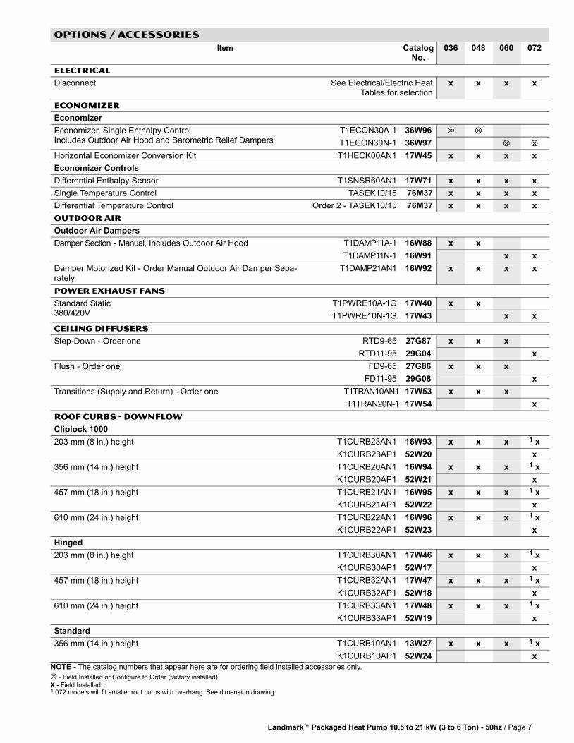
OPTIONs / ACCESSORIES
Item CatalogNo.
036 048 060 072
ELECTRICAL
Disconnect See Electrical/Electric HeatTables for selection
x x x x
ECONOMIZER
Economizer
Economizer, Single Enthalpy ControlIncludes Outdoor Air Hood and Barometric Relief Dampers
T1ECON30A−1 36W96 � �
T1ECON30N−1 36W97 � �
Horizontal Economizer Conversion Kit T1HECK00AN1 17W45 x x x x
Economizer Controls
Differential Enthalpy Sensor T1SNSR60AN1 17W71 x x x x
Single Temperature Control TASEK10/15 76M37 x x x x
Differential Temperature Control Order 2 − TASEK10/15 76M37 x x x x
OUTDOOR AIR
Outdoor Air Dampers
Damper Section − Manual, Includes Outdoor Air Hood T1DAMP11A−1 16W88 x x
T1DAMP11N−1 16W91 x x
Damper Motorized Kit − Order Manual Outdoor Air Damper Sepa-rately
T1DAMP21AN1 16W92 x x x x
POWER EXHAUST FANS
Standard Static380/420V
T1PWRE10A−1G 17W40 x x
T1PWRE10N−1G 17W43 x x
CEILING DIFFUSERS
Step−Down − Order one RTD9−65 27G87 x x x
RTD11−95 29G04 x
Flush − Order one FD9−65 27G86 x x x
FD11−95 29G08 x
Transitions (Supply and Return) − Order one T1TRAN10AN1 17W53 x x x
T1TRAN20N−1 17W54 x
ROOF CURBS − downFlow
Cliplock 1000
203 mm (8 in.) height T1CURB23AN1 16W93 x x x 1 x
K1CURB23AP1 52W20 x
356 mm (14 in.) height T1CURB20AN1 16W94 x x x 1 x
K1CURB20AP1 52W21 x
457 mm (18 in.) height T1CURB21AN1 16W95 x x x 1 x
K1CURB21AP1 52W22 x
610 mm (24 in.) height T1CURB22AN1 16W96 x x x 1 x
K1CURB22AP1 52W23 x
Hinged
203 mm (8 in.) height T1CURB30AN1 17W46 x x x 1 x
K1CURB30AP1 52W17 x
457 mm (18 in.) height T1CURB32AN1 17W47 x x x 1 x
K1CURB32AP1 52W18 x
610 mm (24 in.) height T1CURB33AN1 17W48 x x x 1 x
K1CURB33AP1 52W19 x
Standard
356 mm (14 in.) height T1CURB10AN1 13W27 x x x 1 x
K1CURB10AP1 52W24 x
NOTE − The catalog numbers that appear here are for ordering field installed accessories only.
− Field Installed or Configure to Order (factory installed)
X − Field Installed.1 072 models will fit smaller roof curbs with overhang. See dimension drawing.
Landmark� Packaged Heat Pump 10.5 to 21 kW (3 to 6 Ton) − 50hz / Page 8
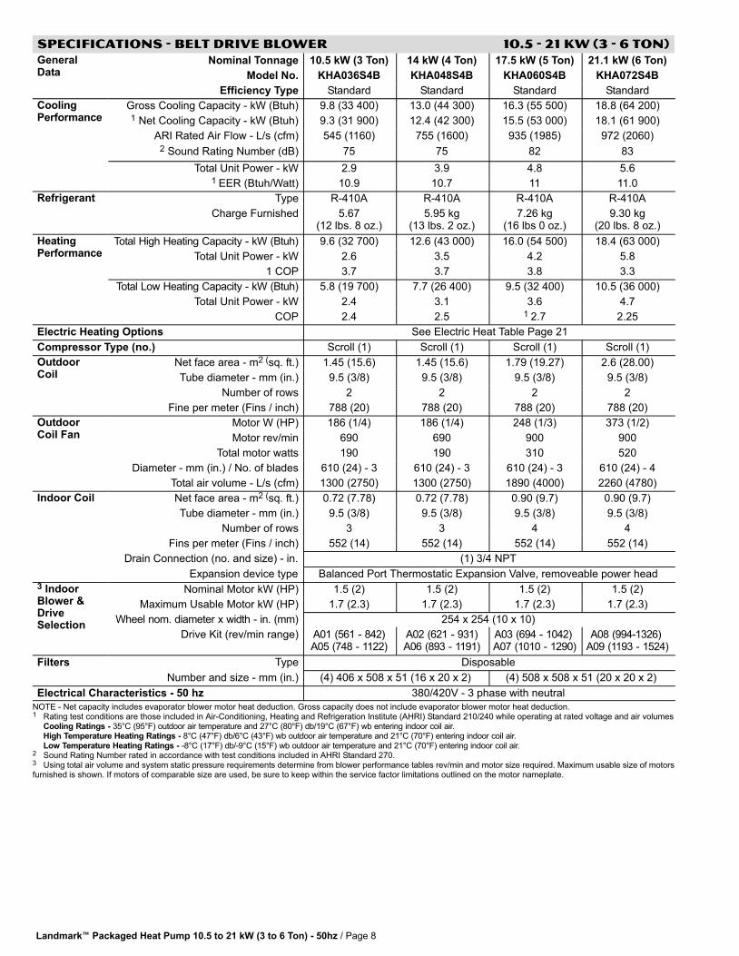
SPECIFICATIONS − BELT DRIVE BLOWER 10.5 − 21 kW (3 − 6 Ton)GeneralData
Nominal Tonnage 10.5 kW (3 Ton) 14 kW (4 Ton) 17.5 kW (5 Ton) 21.1 kW (6 Ton)
Model No. KHA036S4B KHA048S4B KHA060S4B KHA072S4B
Efficiency Type Standard Standard Standard Standard
CoolingPerformance
Gross Cooling Capacity − kW (Btuh) 9.8 (33 400) 13.0 (44 300) 16.3 (55 500) 18.8 (64 200)1 Net Cooling Capacity − kW (Btuh) 9.3 (31 900) 12.4 (42 300) 15.5 (53 000) 18.1 (61 900)
ARI Rated Air Flow − L/s (cfm) 545 (1160) 755 (1600) 935 (1985) 972 (2060)2 Sound Rating Number (dB) 75 75 82 83
Total Unit Power − kW 2.9 3.9 4.8 5.61 EER (Btuh/Watt) 10.9 10.7 11 11.0
Refrigerant Type R−410A R−410A R−410A R−410A
Charge Furnished 5.67(12 lbs. 8 oz.)
5.95 kg(13 lbs. 2 oz.)
7.26 kg(16 lbs 0 oz.)
9.30 kg(20 lbs. 8 oz.)
HeatingPerformance
Total High Heating Capacity − kW (Btuh) 9.6 (32 700) 12.6 (43 000) 16.0 (54 500) 18.4 (63 000)
Total Unit Power − kW 2.6 3.5 4.2 5.8
1 COP 3.7 3.7 3.8 3.3
Total Low Heating Capacity − kW (Btuh) 5.8 (19 700) 7.7 (26 400) 9.5 (32 400) 10.5 (36 000)
Total Unit Power − kW 2.4 3.1 3.6 4.7
COP 2.4 2.5 1 2.7 2.25
Electric Heating Options See Electric Heat Table Page 21
Compressor Type (no.) Scroll (1) Scroll (1) Scroll (1) Scroll (1)
OutdoorCoil
Net face area − m2 (sq. ft.) 1.45 (15.6) 1.45 (15.6) 1.79 (19.27) 2.6 (28.00)
Tube diameter − mm (in.) 9.5 (3/8) 9.5 (3/8) 9.5 (3/8) 9.5 (3/8)
Number of rows 2 2 2 2
Fine per meter (Fins / inch) 788 (20) 788 (20) 788 (20) 788 (20)
OutdoorCoil Fan
Motor W (HP) 186 (1/4) 186 (1/4) 248 (1/3) 373 (1/2)
Motor rev/min 690 690 900 900
Total motor watts 190 190 310 520
Diameter − mm (in.) / No. of blades 610 (24) − 3 610 (24) − 3 610 (24) − 3 610 (24) − 4
Total air volume − L/s (cfm) 1300 (2750) 1300 (2750) 1890 (4000) 2260 (4780)
Indoor Coil Net face area − m2 (sq. ft.) 0.72 (7.78) 0.72 (7.78) 0.90 (9.7) 0.90 (9.7)
Tube diameter − mm (in.) 9.5 (3/8) 9.5 (3/8) 9.5 (3/8) 9.5 (3/8)
Number of rows 3 3 4 4
Fins per meter (Fins / inch) 552 (14) 552 (14) 552 (14) 552 (14)
Drain Connection (no. and size) − in. (1) 3/4 NPT
Expansion device type Balanced Port Thermostatic Expansion Valve, removeable power head3 IndoorBlower &DriveSelection
Nominal Motor kW (HP) 1.5 (2) 1.5 (2) 1.5 (2) 1.5 (2)
Maximum Usable Motor kW (HP) 1.7 (2.3) 1.7 (2.3) 1.7 (2.3) 1.7 (2.3)
Wheel nom. diameter x width − in. (mm) 254 x 254 (10 x 10)
Drive Kit (rev/min range) A01 (561 − 842)A05 (748 − 1122)
A02 (621 − 931)A06 (893 − 1191)
A03 (694 − 1042) A07 (1010 − 1290)
A08 (994−1326) A09 (1193 − 1524)
Filters Type Disposable
Number and size − mm (in.) (4) 406 x 508 x 51 (16 x 20 x 2) (4) 508 x 508 x 51 (20 x 20 x 2)
Electrical Characteristics − 50 hz 380/420V − 3 phase with neutral
NOTE − Net capacity includes evaporator blower motor heat deduction. Gross capacity does not include evaporator blower motor heat deduction.1 Rating test conditions are those included in Air−Conditioning, Heating and Refrigeration Institute (AHRI) Standard 210/240 while operating at rated voltage and air volumes
Cooling Ratings − 35°C (95°F) outdoor air temperature and 27°C (80°F) db/19°C (67°F) wb entering indoor coil air.High Temperature Heating Ratings − 8°C (47°F) db/6°C (43°F) wb outdoor air temperature and 21°C (70°F) entering indoor coil air.Low Temperature Heating Ratings − -8°C (17°F) db/-9°C (15°F) wb outdoor air temperature and 21°C (70°F) entering indoor coil air.
2 Sound Rating Number rated in accordance with test conditions included in AHRI Standard 270.3 Using total air volume and system static pressure requirements determine from blower performance tables rev/min and motor size required. Maximum usable size of motorsfurnished is shown. If motors of comparable size are used, be sure to keep within the service factor limitations outlined on the motor nameplate.

Landmark� Packaged Heat Pump 10.5 to 21 kW (3 to 6 Ton) − 50hz / Page 9
COOLING / HEATING RATINGS
NOTE − For Temperatures and Capacities not shown in tables, see bulletin − Cooling Unit Rating Table Correction Factor Data in Miscellaneous Engineering Data section.
10.6 kW (3 Ton) STANDARD EFFICIENCY − COOLING CAPACITY KHA036S4
EnteringWet BulbTemperat
ure
TotalAir
Volume
Outdoor Air Temperature Entering Outdoor Coil
27�C (80�F) 35�C (95�F) 43�C (110�F) 52�C (125�F)
TotalCoolingCapacity
CompMotor
kWInput
Sensible To TotalRatio (S/T)Dry Bulb
TotalCoolingCapacity
CompMotor
kWInput
Sensible To TotalRatio (S/T)Dry Bulb
TotalCoolingCapacity
CompMotor
kWInput
Sensible To TotalRatio (S/T)Dry Bulb
TotalCoolingCapacity
CompMotor
kWInput
Sensible To TotalRatio (S/T)Dry Bulb
m3/s cfm kW kBtuh24�C75�F
27�C80�F
29�C85�F
kW kBtuh24�C75�F
27�C80�F
29�C85�F
kW kBtuh24�C75�F
27�C80�F
29�C85�F
kW kBtuh24�C75�F
27�C80�F
29�C85�F
17�C(63�F)
.45 960 9.6 32.7 1.88 .74 .88 1.00 8.9 30.4 2.27 .76 .92 1.00 8.2 27.9 2.76 .79 .96 1.00 7.4 25.1 3.37 .84 1.00 1.00
.56 1200 10.0 34.0 1.88 .80 .97 1.00 9.3 31.8 2.28 .83 1.00 1.00 8.6 29.4 2.77 .87 1.00 1.00 7.8 26.7 3.37 .93 1.00 1.00
.68 1440 10.4 35.4 1.89 .86 1.00 1.00 9.7 33.2 2.29 .90 1.00 1.00 9.0 30.7 2.78 .94 1.00 1.00 8.1 27.8 3.38 1.00 1.00 1.00
19�C(67�F)
.45 960 10.2 34.9 1.89 .57 .71 .85 9.5 32.4 2.29 .58 .73 .88 8.7 29.7 2.77 .60 .76 .93 7.8 26.5 3.37 .63 .81 .98
.56 1200 10.6 36.0 1.90 .61 .77 .94 9.8 33.4 2.30 .63 .80 .97 8.9 30.5 2.78 .65 .85 1.00 8.0 27.3 3.38 .68 .90 1.00
.68 1440 10.8 36.8 1.91 .65 .84 1.00 10.0 34.2 2.31 .67 .87 1.00 9.2 31.3 2.79 .70 .92 1.00 8.2 27.9 3.38 .74 .98 1.00
22�C(71�F)
.45 960 10.9 37.2 1.91 .42 .55 .68 10.2 34.7 2.31 .43 .57 .71 9.3 31.7 2.79 .44 .59 .74 8.3 28.3 3.39 .45 .62 .79
.56 1200 11.2 38.3 1.92 .44 .60 .75 10.4 35.6 2.32 .44 .61 .78 9.5 32.5 2.80 .46 .64 .82 8.5 29.0 3.40 .47 .68 .88
.68 1440 11.5 39.1 1.93 .45 .64 .82 10.6 36.2 2.33 .46 .66 .85 9.7 33.1 2.81 .47 .69 .90 8.6 29.4 3.41 .49 .74 .96
10.6 kW (3 Ton) STANDARD EFFICIENCY − HEATING CAPACITY KHA036S4
Indoor CoilAir Volume
21�C db(70�F db)
Air Temperature Entering Outdoor Coil
18�C (65�F) 7�C (45�F) minus 4�C (25�F) minus 15�C (5�F) minus 28�C (minus 15�F)
Total HeatingCapacity
Comp.Motor
kWInput
Total HeatingCapacity
Comp.Motor
kWInput
Total HeatingCapacity
Comp.Motor
kWInput
Total HeatingCapacity
Comp.Motor
kWInput
Total HeatingCapacity
Comp.Motor
kWInputm3/s cfm kW kBtuh kW kBtuh kW kBtuh kW kBtuh kW kBtuh
0.46 960 11.6 39.6 2.20 8.8 30.1 2.05 5.8 19.9 1.88 4.1 14.1 1.71 2.0 6.9 1.28
0.57 1200 11.8 40.4 2.07 9.1 30.9 1.92 6.1 20.7 1.76 4.4 14.9 1.58 2.3 7.7 1.15
0.68 1440 12.0 41.1 1.99 9.3 31.6 1.84 6.3 21.4 1.68 4.6 15.6 1.50 2.5 8.4 1.07
14.1 kW (4 Ton) STANDARD EFFICIENCY − COOLING CAPACITY KHA048S4
EnteringWet BulbTempera-
ture
TotalAir
Volume
Outdoor Air Temperature Entering Outdoor Coil
27�C (80�F) 35�C (95�F) 43�C (110�F) 52�C (125�F)
TotalCoolingCapacity
CompMotor
kWInput
Sensible To TotalRatio (S/T)Dry Bulb
TotalCoolingCapacity
CompMotor
kWInput
Sensible To TotalRatio (S/T)Dry Bulb
TotalCoolingCapacity
CompMotor
kWInput
Sensible To TotalRatio (S/T)Dry Bulb
TotalCoolingCapacity
CompMotor
kWInput
Sensible To TotalRatio (S/T)Dry Bulb
m3/s cfm kW kBtuh24�C75�F
27�C80�F
29�C85�F
kW kBtuh24�C75�F
27�C80�F
29�C85�F
kW kBtuh24�C75�F
27�C80�F
29�C85�F
kW kBtuh24�C75�F
27�C80�F
29�C85�F
17�C(63�F)
.60 1280 12.8 43.7 2.55 .72 .88 1.00 11.9 40.6 3.11 .75 .92 1.00 10.9 37.2 3.77 .78 .97 1.00 9.9 33.7 4.57 .83 1.00 1.00
.75 1600 13.3 45.5 2.55 .78 .97 1.00 12.4 42.3 3.13 .82 1.00 1.00 11.5 39.2 3.78 .86 1.00 1.00 10.4 35.6 4.59 .92 1.00 1.00
.90 1920 13.9 47.3 2.55 .85 1.00 1.00 12.9 44.1 3.14 .89 1.00 1.00 12.0 40.8 3.80 .94 1.00 1.00 10.8 36.9 4.61 .99 1.00 1.00
19�C(67�F)
.60 1280 13.6 46.5 2.55 .56 .70 .84 12.6 43.0 3.14 .57 .72 .88 11.5 39.3 3.79 .59 .75 .93 10.3 35.2 4.59 .62 .80 .99
.75 1600 14.1 48.0 2.56 .60 .76 .93 13.0 44.3 3.15 .62 .79 .98 11.8 40.4 3.81 .64 .84 1.00 10.6 36.2 4.61 .68 .90 1.00
.90 1920 14.3 48.9 2.56 .63 .83 1.00 13.2 45.2 3.16 .66 .87 1.00 12.1 41.3 3.82 .69 .92 1.00 10.8 37.0 4.62 .73 .98 1.00
22�C(71�F)
.60 1280 14.5 49.6 2.56 .41 .54 .67 13.5 45.9 3.16 .42 .56 .70 12.3 41.9 3.83 .43 .58 .73 11.0 37.5 4.63 .44 .61 .78
.75 1600 14.9 51.0 2.56 .43 .58 .74 13.8 47.0 3.17 .44 .60 .77 12.6 42.9 3.84 .45 .63 .81 11.2 38.3 4.64 .46 .67 .88
.90 1920 15.2 51.9 2.56 .44 .62 .80 14.0 47.8 3.18 .45 .65 .85 12.7 43.5 3.85 .47 .68 .90 11.4 38.8 4.65 .48 .73 .97
14.1 kW (4 Ton) STANDARD EFFICIENCY − HEATING CAPACITY KHA048S4
Indoor CoilAir Volume
21�C db(70�F db)
Air Temperature Entering Outdoor Coil
18�C (65�F) 7�C (45�F) minus 4�C (25�F) minus 15�C (5�F) minus 28�C (minus 15�F)
Total HeatingCapacity
Comp.Motor
kWInput
Total HeatingCapacity
Comp.Motor
kWInput
Total HeatingCapacity
Comp.Motor
kWInput
Total HeatingCapacity
Comp.Motor
kWInput
Total HeatingCapacity
Comp.Motor
kWInputm3/s cfm kW kBtuh kW kBtuh kW kBtuh kW kBtuh kW kBtuh
0.61 1280 15.2 51.9 3.01 11.6 39.5 2.77 7.7 26.2 2.52 5.6 19.1 2.26 2.8 9.4 1.69
0.76 1600 15.5 52.9 2.84 11.9 40.5 2.60 8.0 27.2 2.35 5.9 20.1 2.09 3.0 10.4 1.53
0.91 1920 15.8 53.8 2.75 12.1 41.4 2.51 8.2 28.1 2.26 6.2 21.0 2.00 3.3 11.3 1.43
17.5 kW (5 Ton) STANDARD EFFICIENCY − COOLING CAPACITY KHA060S4
EnteringWet BulbTempera-
ture
TotalAir
Volume
Outdoor Air Temperature Entering Outdoor Coil
27�C (80�F) 35�C (95�F) 43�C (110�F) 52�C (125�F)
TotalCoolingCapacity
CompMotor
kWInput
Sensible To TotalRatio (S/T)Dry Bulb
TotalCoolingCapacity
CompMotor
kWInput
Sensible To TotalRatio (S/T)Dry Bulb
TotalCoolingCapacity
CompMotor
kWInput
Sensible To TotalRatio (S/T)Dry Bulb
TotalCoolingCapacity
CompMotor
kWInput
Sensible To TotalRatio (S/T)Dry Bulb
m3/s cfm kW kBtuh24�C75�F
27�C80�F
29�C85�F
kW kBtuh24�C75�F
27�C80�F
29�C85�F
kW kBtuh24�C75�F
27�C80�F
29�C85�F
kW kBtuh24�C75�F
27�C80�F
29�C85�F
17�C(63�F)
.75 1600 16.0 54.7 3.11 .73 .87 1.00 14.8 50.6 3.74 .75 .92 1.00 13.5 46.1 4.52 .78 .97 1.00 12.1 41.2 5.49 .84 1.00 1.00
.94 2000 16.7 56.9 3.13 .79 .97 1.00 15.5 52.8 3.77 .82 1.00 1.00 14.2 48.6 4.55 .87 1.00 1.00 12.8 43.7 5.51 .94 1.00 1.00
1.13 2400 17.4 59.3 3.15 .85 1.00 1.00 16.2 55.3 3.79 .90 1.00 1.00 14.9 50.8 4.57 .95 1.00 1.00 13.3 45.4 5.53 1.00 1.00 1.00
19�C(67�F)
.75 1600 17.1 58.2 3.15 .56 .70 .84 15.8 53.8 3.78 .58 .73 .88 14.3 48.9 4.55 .60 .76 .93 12.6 43.1 5.51 .63 .82 1.00
.94 2000 17.6 60.1 3.17 .60 .76 .93 16.3 55.5 3.80 .62 .80 .98 14.7 50.3 4.58 .65 .85 1.00 13.0 44.4 5.53 .69 .92 1.00
1.13 2400 18.0 61.5 3.19 .64 .83 1.00 16.6 56.7 3.82 .66 .88 1.00 15.1 51.5 4.59 .70 .93 1.00 13.3 45.5 5.55 .75 1.00 1.00
22�C(71�F)
.75 1600 18.2 62.2 3.19 .42 .55 .68 16.8 57.4 3.83 .42 .56 .70 15.3 52.1 4.60 .43 .59 .74 13.5 46.0 5.55 .44 .62 .79
.94 2000 18.8 64.0 3.22 .43 .59 .74 17.3 59.0 3.85 .44 .61 .77 15.6 53.4 4.62 .45 .64 .82 13.8 47.0 5.57 .47 .68 .89
1.13 2400 19.1 65.2 3.23 .45 .63 .81 17.6 60.0 3.87 .46 .66 .85 15.9 54.3 4.64 .47 .69 .91 14.0 47.7 5.59 .50 .74 .98
17.5 kW (5 Ton) STANDARD EFFICIENCY − HEATING CAPACITY KHA060S4
Indoor CoilAir Volume
21�C db(70�F db)
Air Temperature Entering Outdoor Coil
18�C (65�F) 7�C (45�F) minus 4�C (25�F) minus 15�C (5�F) minus 28�C (minus 15�F)
Total HeatingCapacity
Comp.Motor
kWInput
Total HeatingCapacity
Comp.Motor
kWInput
Total HeatingCapacity
Comp.Motor
kWInput
Total HeatingCapacity
Comp.Motor
kWInput
Total HeatingCapacity
Comp.Motor
kWInputm3/s cfm kW kBtuh kW kBtuh kW kBtuh kW kBtuh kW kBtuh
0.76 1600 19.5 66.6 3.53 14.8 50.6 3.28 9.9 33.7 3.03 6.8 23.3 2.68 3.4 11.6 2.01
0.95 2000 19.8 67.7 3.33 15.2 51.7 3.08 10.2 34.8 2.83 7.2 24.4 2.48 3.7 12.7 1.81
1.14 2400 20.3 69.2 3.21 15.6 53.2 2.96 10.6 36.3 2.71 7.6 25.9 2.36 4.2 14.2 1.69

Landmark� Packaged Heat Pump 10.5 to 21 kW (3 to 6 Ton) − 50hz / Page 10
COOLING / HEATING RATINGS
NOTE − For Temperatures and Capacities not shown in tables, see bulletin − Cooling Unit Rating Table Correction Factor Data in Miscellaneous Engineering Data section.
21.1 kW (6 Ton) STANDARD EFFICIENCY − COOLING CAPACITY KHA072S4
EnteringWet BulbTemperat
ure
TotalAir
Volume
Outdoor Air Temperature Entering Outdoor Coil
27�C (80�F) 35�C (95�F) 43�C (110�F) 52�C (125�F)
TotalCoolingCapacity
CompMotor
kWInput
Sensible To TotalRatio (S/T)Dry Bulb
TotalCoolingCapacity
CompMotor
kWInput
Sensible To TotalRatio (S/T)Dry Bulb
TotalCoolingCapacity
CompMotor
kWInput
Sensible To TotalRatio (S/T)Dry Bulb
TotalCoolingCapacity
CompMotor
kWInput
Sensible To TotalRatio (S/T)Dry Bulb
m3/s cfm kW kBtuh24�C75�F
27�C80�F
29�C85�F
kW kBtuh24�C75�F
27�C80�F
29�C85�F
kW kBtuh24�C75�F
27�C80�F
29�C85�F
kW kBtuh24�C75�F
27�C80�F
29�C85�F
17�C(63�F)
.90 1920 19.0 64.8 3.79 .73 .89 1.00 17.7 60.5 4.44 .75 .93 1.00 16.3 55.5 5.21 .78 .99 1.00 14.7 50.1 6.14 .84 1.00 1.00
1.13 2400 20.0 68.1 3.80 .78 .98 1.00 18.7 63.7 4.44 .82 1.00 1.00 17.3 59.1 5.22 .87 1.00 1.00 15.7 53.5 6.14 .95 1.00 1.00
1.36 2880 20.9 71.3 3.80 .85 1.00 1.00 19.6 67.0 4.45 .89 1.00 1.00 18.2 62.0 5.22 .95 1.00 1.00 16.4 55.9 6.15 1.00 1.00 1.00
19�C(67�F)
.90 1920 20.1 68.7 3.80 .57 .70 .85 18.8 64.1 4.44 .58 .73 .89 17.2 58.7 5.21 .60 .76 .95 15.4 52.4 6.14 .63 .81 1.00
1.13 2400 21.0 71.7 3.80 .61 .76 .95 19.5 66.7 4.45 .62 .79 .99 17.9 61.0 5.22 .65 .84 1.00 15.9 54.4 6.14 .68 .92 1.00
1.36 2880 21.7 74.1 3.81 .64 .82 1.00 20.1 68.7 4.45 .66 .87 1.00 18.5 63.0 5.22 .69 .92 1.00 16.4 56.0 6.14 .73 1.00 1.00
22�C(71�F)
.90 1920 21.3 72.7 3.80 .43 .56 .68 19.9 67.9 4.45 .43 .57 .70 18.3 62.3 5.22 .44 .59 .74 16.3 55.7 6.14 .45 .62 .78
1.13 2400 22.2 75.9 3.81 .44 .59 .74 20.7 70.8 4.45 .45 .61 .77 19.0 64.8 5.22 .46 .64 .81 16.9 57.8 6.15 .47 .67 .88
1.36 2880 22.9 78.3 3.82 .46 .63 .79 21.3 72.8 4.45 .47 .65 .84 19.5 66.6 5.22 .48 .68 .89 17.3 59.1 6.15 .50 .73 .98
21.1 kW (6 Ton) STANDARD EFFICIENCY − HEATING CAPACITY KHA072S4
Indoor CoilAir Volume
21�C db(70�F db)
Air Temperature Entering Outdoor Coil
18�C (65�F) 7�C (45�F) minus 4�C (25�F) minus 15�C (5�F) minus 28�C (minus 15�F)
Total HeatingCapacity
Comp.Motor
kWInput
Total HeatingCapacity
Comp.Motor
kWInput
Total HeatingCapacity
Comp.Motor
kWInput
Total HeatingCapacity
Comp.Motor
kWInput
Total HeatingCapacity
Comp.Motor
kWInputm3/s cfm kW kBtuh kW kBtuh kW kBtuh kW kBtuh kW kBtuh
0.91 1920 22.9 78.2 4.65 17.4 59.5 4.14 11.9 40.6 3.59 7.3 24.9 3.22 3.5 12.1 2.43
1.14 2400 23.5 80.2 4.42 18.1 61.6 3.91 12.5 42.7 3.37 7.9 26.9 3.00 4.1 14.1 2.21
1.36 2880 24.0 81.8 4.28 18.5 63.1 3.78 13.0 44.2 3.23 8.4 28.5 2.86 4.6 15.7 2.07
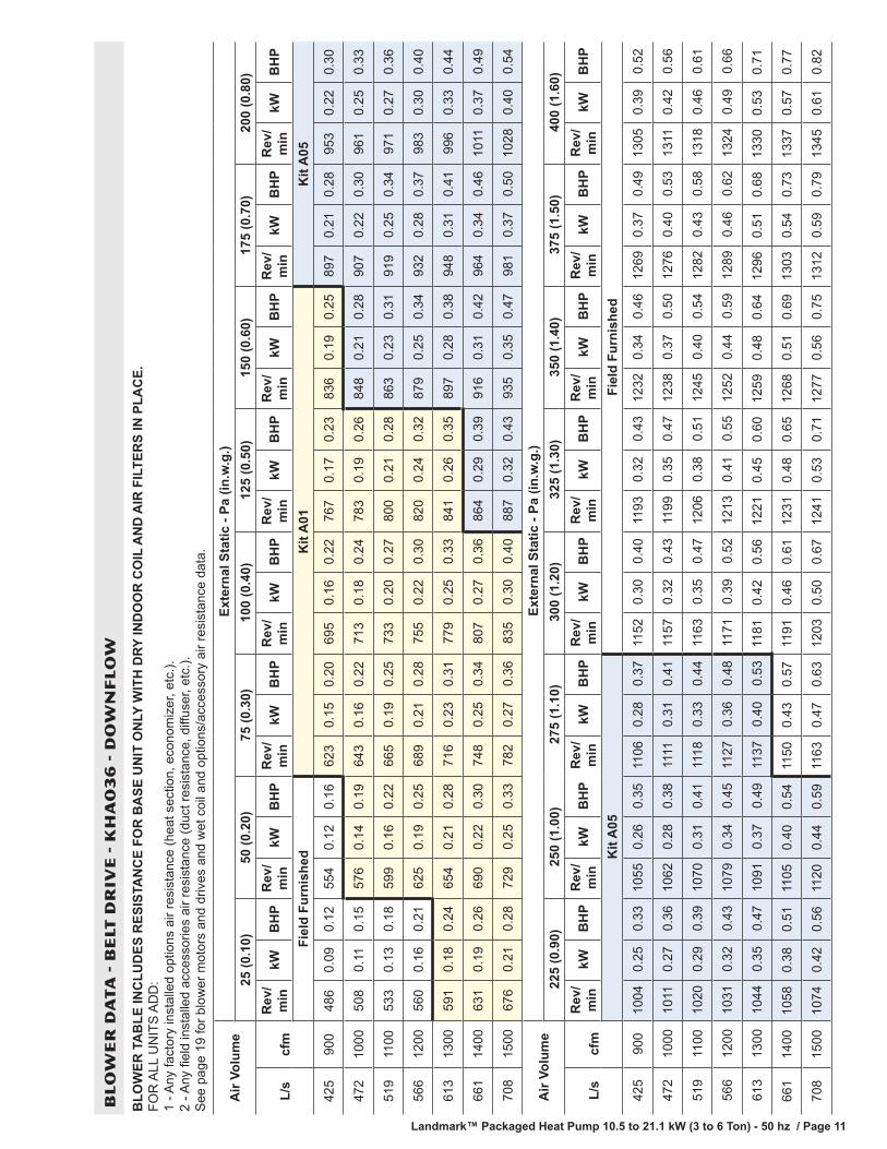
Landmark™ Packaged Heat Pump 10.5 to 21.1 kW (3 to 6 Ton) - 50 hz / Page 11
BL
OW
ER
DA
TA
- B
ELT
DR
IVE
- K
HA
03
6 -
DO
WN
FL
OW
BLO
WER
TA
BLE
INC
LUD
ES R
ESIS
TAN
CE
FOR
BA
SE U
NIT
ON
LY W
ITH
DRY
IND
OO
R C
OIL
AN
D A
IR F
ILTE
RS
IN P
LAC
E.
FOR
ALL
UN
ITS
AD
D:
1 - A
ny fa
ctor
y in
stal
led
optio
ns a
ir re
sist
ance
(hea
t sec
tion,
eco
nom
izer
, etc
.).
2 - A
ny fi
eld
inst
alle
d ac
cess
orie
s ai
r res
ista
nce
(duc
t res
ista
nce,
diff
user
, etc
.).
See
pag
e 19
for b
low
er m
otor
s an
d dr
ives
and
wet
coi
l and
opt
ions
/acc
esso
ry a
ir re
sist
ance
dat
a.
Air
Volu
me
Exte
rnal
Sta
tic -
Pa (i
n.w
.g.)
25 (0
.10)
50 (0
.20)
75 (0
.30)
100
(0.4
0)12
5 (0
.50)
150
(0.6
0)17
5 (0
.70)
200
(0.8
0)
L/s
cfm
Rev
/m
inkW
BH
PR
ev/
min
kWB
HP
Rev
/m
inkW
BH
PR
ev/
min
kWB
HP
Rev
/m
inkW
BH
PR
ev/
min
kWB
HP
Rev
/m
inkW
BH
PR
ev/
min
kWB
HP
Fiel
d Fu
rnis
hed
Kit
A01
Kit
A05
425
900
486
0.09
0.12
554
0.12
0.16
623
0.15
0.20
695
0.16
0.22
767
0.17
0.23
836
0.19
0.25
897
0.21
0.28
953
0.22
0.30
472
1000
508
0.11
0.15
576
0.14
0.19
643
0.16
0.22
713
0.18
0.24
783
0.19
0.26
848
0.21
0.28
907
0.22
0.30
961
0.25
0.33
519
1100
533
0.13
0.18
599
0.16
0.22
665
0.19
0.25
733
0.20
0.27
800
0.21
0.28
863
0.23
0.31
919
0.25
0.34
971
0.27
0.36
566
1200
560
0.16
0.21
625
0.19
0.25
689
0.21
0.28
755
0.22
0.30
820
0.24
0.32
879
0.25
0.34
932
0.28
0.37
983
0.30
0.40
613
1300
591
0.18
0.24
654
0.21
0.28
716
0.23
0.31
779
0.25
0.33
841
0.26
0.35
897
0.28
0.38
948
0.31
0.41
996
0.33
0.44
661
1400
631
0.19
0.26
690
0.22
0.30
748
0.25
0.34
807
0.27
0.36
864
0.29
0.39
916
0.31
0.42
964
0.34
0.46
1011
0.37
0.49
708
1500
676
0.21
0.28
729
0.25
0.33
782
0.27
0.36
835
0.30
0.40
887
0.32
0.43
935
0.35
0.47
981
0.37
0.50
1028
0.40
0.54
Air
Volu
me
Exte
rnal
Sta
tic -
Pa (i
n.w
.g.)
225
(0.9
0)25
0 (1
.00)
275
(1.1
0)30
0 (1
.20)
325
(1.3
0)35
0 (1
.40)
375
(1.5
0)40
0 (1
.60)
L/s
cfm
Rev
/m
inkW
BH
PR
ev/
min
kWB
HP
Rev
/m
inkW
BH
PR
ev/
min
kWB
HP
Rev
/m
inkW
BH
PR
ev/
min
kWB
HP
Rev
/m
inkW
BH
PR
ev/
min
kWB
HP
Kit
A05
Fiel
d Fu
rnis
hed
425
900
1004
0.25
0.33
1055
0.26
0.35
1106
0.28
0.37
1152
0.30
0.40
1193
0.32
0.43
1232
0.34
0.46
1269
0.37
0.49
1305
0.39
0.52
472
1000
1011
0.27
0.36
1062
0.28
0.38
1111
0.31
0.41
1157
0.32
0.43
1199
0.35
0.47
1238
0.37
0.50
1276
0.40
0.53
1311
0.42
0.56
519
1100
1020
0.29
0.39
1070
0.31
0.41
1118
0.33
0.44
1163
0.35
0.47
1206
0.38
0.51
1245
0.40
0.54
1282
0.43
0.58
1318
0.46
0.61
566
1200
1031
0.32
0.43
1079
0.34
0.45
1127
0.36
0.48
1171
0.39
0.52
1213
0.41
0.55
1252
0.44
0.59
1289
0.46
0.62
1324
0.49
0.66
613
1300
1044
0.35
0.47
1091
0.37
0.49
1137
0.40
0.53
1181
0.42
0.56
1221
0.45
0.60
1259
0.48
0.64
1296
0.51
0.68
1330
0.53
0.71
661
1400
1058
0.38
0.51
1 105
0.40
0.54
1150
0.43
0.57
1191
0.46
0.61
1231
0.48
0.65
1268
0.51
0.69
1303
0.54
0.73
1337
0.57
0.77
708
1500
1074
0.42
0.56
1120
0.44
0.59
1163
0.47
0.63
1203
0.50
0.67
1241
0.53
0.71
1277
0.56
0.75
1312
0.59
0.79
1345
0.61
0.82

Landmark™ Packaged Heat Pump 10.5 to 21.1 kW (3 to 6 Ton) - 50 hz / Page 12 Landmark™ Packaged Heat Pump 10.5 to 21.1 kW (3 to 6 Ton) - 50 hz / Page 13
BL
OW
ER
DA
TA
- B
ELT
DR
IVE
- K
HA
03
6 -
HO
RIZ
ON
TA
L
BLO
WER
TA
BLE
INC
LUD
ES R
ESIS
TAN
CE
FOR
BA
SE U
NIT
ON
LY W
ITH
DRY
IND
OO
R C
OIL
AN
D A
IR F
ILTE
RS
IN P
LAC
E.
FOR
ALL
UN
ITS
AD
D:
1 - A
ny fa
ctor
y in
stal
led
optio
ns a
ir re
sist
ance
(hea
t sec
tion,
eco
nom
izer
, etc
.).
2 - A
ny fi
eld
inst
alle
d ac
cess
orie
s ai
r res
ista
nce
(duc
t res
ista
nce,
diff
user
, etc
.).
See
pag
e 19
for b
low
er m
otor
s an
d dr
ives
and
wet
coi
l and
opt
ions
/acc
esso
ry a
ir re
sist
ance
dat
a.
Air
Volu
me
Exte
rnal
Sta
tic -
Pa (i
n.w
.g.)
25 (0
.10)
50 (0
.20)
75 (0
.30)
100
(0.4
0)12
5 (0
.50)
150
(0.6
0)17
5 (0
.70)
200
(0.8
0)
L/s
cfm
Rev
/m
inkW
BH
PR
ev/
min
kWB
HP
Rev
/m
inkW
BH
PR
ev/
min
kWB
HP
Rev
/m
inkW
BH
PR
ev/
min
kWB
HP
Rev
/m
inkW
BH
PR
ev/
min
kWB
HP
Fiel
d Fu
rnis
hed
Kit
A01
Kit
A05
425
900
485
0.08
0.11
554
0.10
0.14
627
0.12
0.16
703
0.13
0.18
780
0.16
0.21
841
0.17
0.23
888
0.20
0.27
935
0.22
0.30
472
1000
509
0.10
0.13
578
0.12
0.16
649
0.14
0.19
722
0.16
0.21
796
0.17
0.23
854
0.19
0.26
900
0.22
0.29
947
0.25
0.33
519
1100
537
0.12
0.16
605
0.14
0.19
674
0.16
0.21
744
0.18
0.24
813
0.19
0.26
868
0.22
0.29
913
0.25
0.33
959
0.27
0.36
566
1200
567
0.14
0.19
633
0.16
0.22
700
0.18
0.24
768
0.20
0.27
833
0.22
0.30
884
0.25
0.33
928
0.28
0.37
974
0.30
0.40
613
1300
599
0.16
0.22
664
0.19
0.25
729
0.21
0.28
793
0.22
0.30
853
0.25
0.33
902
0.28
0.37
945
0.31
0.41
990
0.33
0.44
661
1400
634
0.19
0.26
697
0.22
0.29
758
0.23
0.31
819
0.25
0.34
875
0.28
0.38
921
0.31
0.42
964
0.34
0.46
1008
0.37
0.49
708
1500
669
0.22
0.30
730
0.25
0.33
789
0.27
0.36
846
0.29
0.39
897
0.31
0.42
941
0.35
0.47
983
0.38
0.51
1028
0.40
0.54
Air
Volu
me
Exte
rnal
Sta
tic -
Pa (i
n.w
.g.)
225
(0.9
0)25
0 (1
.00)
275
(1.1
0)30
0 (1
.20)
325
(1.3
0)35
0 (1
.40)
375
(1.5
0)40
0 (1
.60)
L/s
cfm
Rev
/m
inkW
BH
PR
ev/
min
kWB
HP
Rev
/m
inkW
BH
PR
ev/
min
kWB
HP
Rev
/m
inkW
BH
PR
ev/
min
kWB
HP
Rev
/m
inkW
BH
PR
ev/
min
kWB
HP
Kit
A05
Fiel
d Fu
rnis
hed
425
900
986
0.24
0.32
1039
0.26
0.35
1090
0.28
0.37
1137
0.30
0.40
1177
0.32
0.43
1214
0.34
0.46
1248
0.37
0.49
1280
0.38
0.51
472
1000
997
0.26
0.35
1048
0.28
0.38
1098
0.31
0.41
1143
0.33
0.44
1184
0.35
0.47
1221
0.37
0.50
1255
0.40
0.53
1287
0.42
0.56
519
1100
1008
0.29
0.39
1059
0.31
0.41
1107
0.33
0.44
1150
0.35
0.47
1191
0.38
0.51
1228
0.40
0.54
1263
0.43
0.57
1295
0.45
0.6
566
1200
1022
0.32
0.43
1071
0.34
0.45
1117
0.36
0.48
1160
0.39
0.52
1200
0.41
0.55
1237
0.44
0.59
1271
0.46
0.62
1303
0.49
0.66
613
1300
1037
0.35
0.47
1085
0.37
0.50
1130
0.40
0.53
1171
0.43
0.57
1210
0.45
0.60
1246
0.48
0.64
1280
0.51
0.68
1312
0.53
0.71
661
1400
1054
0.39
0.52
1 100
0.40
0.54
1144
0.43
0.58
1183
0.46
0.62
1221
0.49
0.66
1256
0.52
0.70
1290
0.54
0.73
1321
0.57
0.77
708
1500
1073
0.43
0.57
1117
0.45
0.60
1159
0.48
0.64
1197
0.50
0.67
1234
0.53
0.71
1268
0.56
0.75
1301
0.59
0.79
1332
0.62
0.83
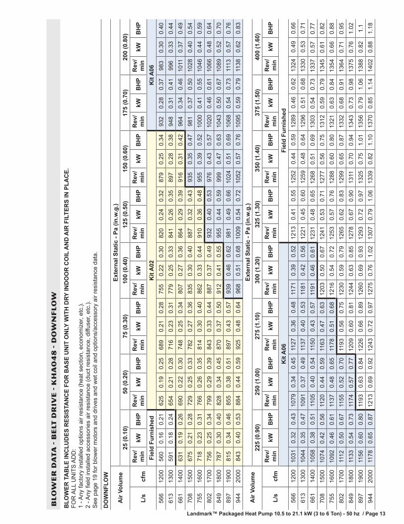
Landmark™ Packaged Heat Pump 10.5 to 21.1 kW (3 to 6 Ton) - 50 hz / Page 12 Landmark™ Packaged Heat Pump 10.5 to 21.1 kW (3 to 6 Ton) - 50 hz / Page 13
BL
OW
ER
DA
TA
- B
ELT
DR
IVE
- K
HA
04
8 -
DO
WN
FL
OW
BLO
WER
TA
BLE
INC
LUD
ES R
ESIS
TAN
CE
FOR
BA
SE U
NIT
ON
LY W
ITH
DRY
IND
OO
R C
OIL
AN
D A
IR F
ILTE
RS
IN P
LAC
E.
FOR
ALL
UN
ITS
AD
D:
1 - A
ny fa
ctor
y in
stal
led
optio
ns a
ir re
sist
ance
(hea
t sec
tion,
eco
nom
izer
, etc
.).
2 - A
ny fi
eld
inst
alle
d ac
cess
orie
s ai
r res
ista
nce
(duc
t res
ista
nce,
diff
user
, etc
.).
See
pag
e 19
for b
low
er m
otor
s an
d dr
ives
and
wet
coi
l and
opt
ions
/acc
esso
ry a
ir re
sist
ance
dat
a.
DO
WN
FLO
W
Air
Volu
me
Exte
rnal
Sta
tic -
Pa (i
n.w
.g.)
25 (0
.10)
50 (0
.20)
75 (0
.30)
100
(0.4
0)12
5 (0
.50)
150
(0.6
0)17
5 (0
.70)
200
(0.8
0)
L/s
cfm
Rev
/m
inkW
BH
PR
ev/
min
kWB
HP
Rev
/m
inkW
BH
PR
ev/
min
kWB
HP
Rev
/m
inkW
BH
PR
ev/
min
kWB
HP
Rev
/m
inkW
BH
PR
ev/
min
kWB
HP
Fiel
d Fu
rnis
hed
Kit
A02
Kit
A06
566
1200
560
0.16
0.21
625
0.19
0.25
689
0.21
0.28
755
0.22
0.30
820
0.24
0.32
879
0.25
0.34
932
0.28
0.37
983
0.30
0.40
613
1300
591
0.18
0.24
654
0.21
0.28
716
0.23
0.31
779
0.25
0.33
841
0.26
0.35
897
0.28
0.38
948
0.31
0.41
996
0.33
0.44
661
1400
631
0.19
0.26
690
0.22
0.30
748
0.25
0.34
807
0.27
0.36
864
0.29
0.39
916
0.31
0.42
964
0.34
0.46
1011
0.37
0.49
708
1500
675
0.21
0.28
729
0.25
0.33
782
0.27
0.36
835
0.30
0.40
887
0.32
0.43
935
0.35
0.47
981
0.37
0.50
1028
0.40
0.54
755
1600
718
0.23
0.31
766
0.26
0.35
814
0.30
0.40
862
0.33
0.44
910
0.36
0.48
955
0.39
0.52
1000
0.41
0.55
1046
0.44
0.59
802
1700
756
0.25
0.34
799
0.29
0.39
843
0.33
0.44
887
0.37
0.49
932
0.40
0.53
976
0.43
0.57
1020
0.46
0.61
1066
0.48
0.64
849
1800
787
0.30
0.40
828
0.34
0.45
870
0.37
0.50
912
0.41
0.55
955
0.44
0.59
999
0.47
0.63
1043
0.50
0.67
1089
0.52
0.70
897
1900
815
0.34
0.46
855
0.38
0.51
897
0.43
0.57
939
0.46
0.62
981
0.49
0.66
1024
0.51
0.69
1068
0.54
0.73
1113
0.57
0.76
944
2000
843
0.40
0.53
884
0.44
0.59
925
0.48
0.64
968
0.51
0.68
1009
0.54
0.72
1052
0.57
0.76
1095
0.59
0.79
1138
0.62
0.83
Air
Volu
me
Exte
rnal
Sta
tic -
Pa (i
n.w
.g.)
225
(0.9
0)25
0 (1
.00)
275
(1.1
0)30
0 (1
.20)
325
(1.3
0)35
0 (1
.40)
375
(1.5
0)40
0 (1
.60)
L/s
cfm
Rev
/m
inkW
BH
PR
ev/
min
kWB
HP
Rev
/m
inkW
BH
PR
ev/
min
kWB
HP
Rev
/m
inkW
BH
PR
ev/
min
kWB
HP
Rev
/m
inkW
BH
PR
ev/
min
kWB
HP
Kit
A06
Fiel
d Fu
rnis
hed
566
1200
1031
0.32
0.43
1079
0.34
0.45
1127
0.36
0.48
1171
0.39
0.52
1213
0.41
0.55
1252
0.44
0.59
1289
0.46
0.62
1324
0.49
0.66
613
1300
1044
0.35
0.47
1091
0.37
0.49
1137
0.40
0.53
1181
0.42
0.56
1221
0.45
0.60
1259
0.48
0.64
1296
0.51
0.68
1330
0.53
0.71
661
1400
1058
0.38
0.51
1105
0.40
0.54
1150
0.43
0.57
1 191
0.46
0.61
1231
0.48
0.65
1268
0.51
0.69
1303
0.54
0.73
1337
0.57
0.77
708
1500
1074
0.42
0.56
1120
0.44
0.59
1163
0.47
0.63
1203
0.50
0.67
1241
0.53
0.71
1277
0.56
0.75
1312
0.59
0.79
1345
0.61
0.82
755
1600
1092
0.46
0.61
1137
0.48
0.65
1178
0.51
0.68
1216
0.54
0.72
1253
0.57
0.76
1288
0.60
0.80
1321
0.63
0.84
1354
0.66
0.88
802
1700
1112
0.50
0.67
1155
0.52
0.70
1193
0.56
0.75
1230
0.59
0.79
1265
0.62
0.83
1299
0.65
0.87
1332
0.68
0.91
1364
0.71
0.95
849
1800
1133
0.54
0.73
1174
0.57
0.77
1209
0.60
0.81
1244
0.63
0.85
1278
0.67
0.90
1311
0.70
0.94
1343
0.73
0.98
1375
0.76
1.02
897
1900
1156
0.60
0.80
1193
0.63
0.84
1226
0.66
0.89
1260
0.69
0.93
1293
0.72
0.97
1325
0.75
1.01
1356
0.79
1.06
1388
0.82
1.1
944
2000
1178
0.65
0.87
1213
0.69
0.92
1243
0.72
0.97
1275
0.76
1.02
1307
0.79
1.06
1339
0.82
1.10
1370
0.85
1.14
1402
0.88
1.18
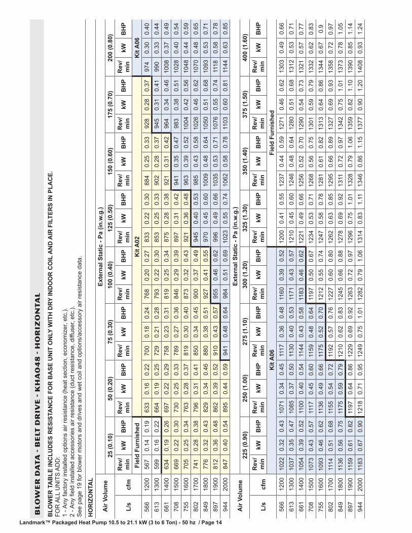
Landmark™ Packaged Heat Pump 10.5 to 21.1 kW (3 to 6 Ton) - 50 hz / Page 14 Landmark™ Packaged Heat Pump 10.5 to 21.1 kW (3 to 6 Ton) - 50 hz / Page 15
BL
OW
ER
DA
TA
- B
ELT
DR
IVE
- K
HA
04
8 -
HO
RIZ
ON
TA
L
BLO
WER
TA
BLE
INC
LUD
ES R
ESIS
TAN
CE
FOR
BA
SE U
NIT
ON
LY W
ITH
DRY
IND
OO
R C
OIL
AN
D A
IR F
ILTE
RS
IN P
LAC
E.
FOR
ALL
UN
ITS
AD
D:
1 - A
ny fa
ctor
y in
stal
led
optio
ns a
ir re
sist
ance
(hea
t sec
tion,
eco
nom
izer
, etc
.).
2 - A
ny fi
eld
inst
alle
d ac
cess
orie
s ai
r res
ista
nce
(duc
t res
ista
nce,
diff
user
, etc
.).
See
pag
e 19
for b
low
er m
otor
s an
d dr
ives
and
wet
coi
l and
opt
ions
/acc
esso
ry a
ir re
sist
ance
dat
a.
HO
RIZ
ON
TAL
Air
Volu
me
Exte
rnal
Sta
tic -
Pa (i
n.w
.g.)
25 (0
.10)
50 (0
.20)
75 (0
.30)
100
(0.4
0)12
5 (0
.50)
150
(0.6
0)17
5 (0
.70)
200
(0.8
0)
L/s
cfm
Rev
/m
inkW
BH
PR
ev/
min
kWB
HP
Rev
/m
inkW
BH
PR
ev/
min
kWB
HP
Rev
/m
inkW
BH
PR
ev/
min
kWB
HP
Rev
/m
inkW
BH
PR
ev/
min
kWB
HP
Fiel
d Fu
rnis
hed
Kit
A02
Kit
A06
566
1200
567
0.14
0.19
633
0.16
0.22
700
0.18
0.24
768
0.20
0.27
833
0.22
0.30
884
0.25
0.33
928
0.28
0.37
974
0.30
0.40
613
1300
599
0.16
0.22
664
0.19
0.25
729
0.21
0.28
793
0.22
0.30
853
0.25
0.33
902
0.28
0.37
945
0.31
0.41
990
0.33
0.44
661
1400
634
0.19
0.26
697
0.22
0.29
758
0.23
0.31
819
0.25
0.34
875
0.28
0.38
921
0.31
0.42
964
0.34
0.46
1008
0.37
0.49
708
1500
669
0.22
0.30
730
0.25
0.33
789
0.27
0.36
846
0.29
0.39
897
0.31
0.42
941
0.35
0.47
983
0.38
0.51
1028
0.40
0.54
755
1600
705
0.25
0.34
763
0.28
0.37
819
0.30
0.40
873
0.32
0.43
921
0.36
0.48
963
0.39
0.52
1004
0.42
0.56
1048
0.44
0.59
802
1700
741
0.28
0.38
796
0.31
0.41
850
0.34
0.45
900
0.37
0.49
945
0.40
0.53
985
0.43
0.58
1026
0.46
0.62
1070
0.48
0.65
849
1800
776
0.32
0.43
829
0.34
0.46
880
0.38
0.51
927
0.41
0.55
970
0.45
0.60
1009
0.48
0.64
1050
0.51
0.68
1093
0.53
0.71
897
1900
812
0.36
0.48
862
0.39
0.52
910
0.43
0.57
955
0.46
0.62
996
0.49
0.66
1035
0.53
0.71
1076
0.55
0.74
1118
0.58
0.78
944
2000
847
0.40
0.54
895
0.44
0.59
941
0.48
0.64
984
0.51
0.69
1023
0.55
0.74
1062
0.58
0.78
1103
0.60
0.81
1144
0.63
0.85
Air
Volu
me
Exte
rnal
Sta
tic -
Pa (i
n.w
.g.)
225
(0.9
0)25
0 (1
.00)
275
(1.1
0)30
0 (1
.20)
325
(1.3
0)35
0 (1
.40)
375
(1.5
0)40
0 (1
.60)
L/s
cfm
Rev
/m
inkW
BH
PR
ev/
min
kWB
HP
Rev
/m
inkW
BH
PR
ev/
min
kWB
HP
Rev
/m
inkW
BH
PR
ev/
min
kWB
HP
Rev
/m
inkW
BH
PR
ev/
min
kWB
HP
Kit
A06
Fiel
d Fu
rnis
hed
566
1200
1022
0.32
0.43
1071
0.34
0.45
1117
0.36
0.48
1160
0.39
0.52
1200
0.41
0.55
1237
0.44
0.59
1271
0.46
0.62
1303
0.49
0.66
613
1300
1037
0.35
0.47
1085
0.37
0.50
1130
0.40
0.53
1171
0.43
0.57
1210
0.45
0.60
1246
0.48
0.64
1280
0.51
0.68
1312
0.53
0.71
661
1400
1054
0.39
0.52
1100
0.40
0.54
1144
0.43
0.58
1 183
0.46
0.62
1221
0.49
0.66
1256
0.52
0.70
1290
0.54
0.73
1321
0.57
0.77
708
1500
1073
0.43
0.57
1117
0.45
0.60
1159
0.48
0.64
1197
0.50
0.67
1234
0.53
0.71
1268
0.56
0.75
1301
0.59
0.79
1332
0.62
0.83
755
1600
1093
0.46
0.62
1136
0.49
0.66
1175
0.52
0.70
1212
0.55
0.74
1247
0.58
0.78
1281
0.61
0.82
1313
0.64
0.86
1344
0.67
0.9
802
1700
1114
0.51
0.68
1155
0.54
0.72
1192
0.57
0.76
1227
0.60
0.80
1262
0.63
0.85
1295
0.66
0.89
1327
0.69
0.93
1358
0.72
0.97
849
1800
1136
0.56
0.75
1175
0.59
0.79
1210
0.62
0.83
1245
0.66
0.88
1278
0.69
0.92
1311
0.72
0.97
1342
0.75
1.01
1373
0.78
1.05
897
1900
1159
0.61
0.82
1197
0.64
0.86
1229
0.69
0.92
1263
0.72
0.97
1296
0.75
1.01
1328
0.79
1.06
1359
0.82
1.10
1390
0.85
1.14
944
2000
1183
0.67
0.90
1218
0.71
0.95
1249
0.75
1.01
1282
0.79
1.06
1314
0.83
1.11
1346
0.86
1.15
1377
0.90
1.20
1408
0.93
1.24

Landmark™ Packaged Heat Pump 10.5 to 21.1 kW (3 to 6 Ton) - 50 hz / Page 14 Landmark™ Packaged Heat Pump 10.5 to 21.1 kW (3 to 6 Ton) - 50 hz / Page 15
BL
OW
ER
DA
TA
- B
ELT
DR
IVE
- K
HA
06
0 -
DO
WN
FL
OW
BLO
WER
TA
BLE
INC
LUD
ES R
ESIS
TAN
CE
FOR
BA
SE U
NIT
ON
LY W
ITH
DRY
IND
OO
R C
OIL
AN
D A
IR F
ILTE
RS
IN P
LAC
E.
FOR
ALL
UN
ITS
AD
D:
1 - A
ny fa
ctor
y in
stal
led
optio
ns a
ir re
sist
ance
(hea
t sec
tion,
eco
nom
izer
, etc
.).
2 - A
ny fi
eld
inst
alle
d ac
cess
orie
s ai
r res
ista
nce
(duc
t res
ista
nce,
diff
user
, etc
.).
See
pag
e 19
for b
low
er m
otor
s an
d dr
ives
and
wet
coi
l and
opt
ions
/acc
esso
ry a
ir re
sist
ance
dat
a.
Air
Volu
me
Exte
rnal
Sta
tic -
Pa (i
n.w
.g.)
25 (0
.10)
50 (0
.20)
75 (0
.30)
100
(0.4
0)12
5 (0
.50)
150
(0.6
0)17
5 (0
.70)
200
(0.8
0)
L/s
cfm
Rev
/m
inkW
BH
PR
ev/
min
kWB
HP
Rev
/m
inkW
BH
PR
ev/
min
kWB
HP
Rev
/m
inkW
BH
PR
ev/
min
kWB
HP
Rev
/m
inkW
BH
PR
ev/
min
kWB
HP
Fiel
d Fu
rnis
hed
Kit
A03
755
1600
665
0.22
0.30
716
0.25
0.34
768
0.28
0.38
819
0.31
0.41
879
0.33
0.44
937
0.34
0.46
985
0.37
0.49
1022
0.39
0.52
802
1700
723
0.23
0.31
768
0.26
0.35
814
0.29
0.39
860
0.32
0.43
910
0.35
0.47
959
0.37
0.50
1001
0.40
0.54
1037
0.43
0.58
849
1800
779
0.24
0.32
818
0.28
0.37
857
0.31
0.41
897
0.34
0.46
939
0.37
0.50
980
0.41
0.55
1018
0.44
0.59
1054
0.48
0.64
897
1900
826
0.27
0.36
859
0.31
0.41
894
0.34
0.45
928
0.37
0.50
964
0.42
0.56
1000
0.46
0.61
1036
0.49
0.66
1072
0.52
0.70
944
2000
857
0.31
0.42
889
0.35
0.47
920
0.39
0.52
952
0.43
0.57
986
0.46
0.62
1020
0.51
0.68
1055
0.54
0.73
1091
0.57
0.77
991
2100
878
0.37
0.49
909
0.40
0.54
940
0.44
0.59
973
0.48
0.64
1006
0.52
0.70
1041
0.56
0.75
1076
0.60
0.80
1112
0.63
0.85
1038
2200
897
0.41
0.55
929
0.46
0.61
961
0.49
0.66
994
0.54
0.72
1028
0.58
0.78
1063
0.62
0.83
1099
0.66
0.89
1134
0.69
0.93
1085
2300
918
0.46
0.62
950
0.51
0.68
983
0.55
0.74
1017
0.60
0.80
1052
0.64
0.86
1087
0.69
0.92
1122
0.72
0.97
1157
0.76
1.02
1133
2400
941
0.52
0.70
974
0.57
0.77
1008
0.62
0.83
1042
0.67
0.90
1077
0.72
0.96
1111
0.75
1.01
1146
0.79
1.06
1181
0.83
1.11
Air
Volu
me
Exte
rnal
Sta
tic -
Pa (i
n.w
.g.)
225
(0.9
0)25
0 (1
.00)
275
(1.1
0)30
0 (1
.20)
325
(1.3
0)35
0 (1
.40)
375
(1.5
0)40
0 (1
.60)
L/s
cfm
Rev
/m
inkW
BH
PR
ev/
min
kWB
HP
Rev
/m
inkW
BH
PR
ev/
min
kWB
HP
Rev
/m
inkW
BH
PR
ev/
min
kWB
HP
Rev
/m
inkW
BH
PR
ev/
min
kWB
HP
Kit
A07
Fiel
d Fu
rnis
hed
755
1600
1059
0.43
0.57
1098
0.46
0.61
1138
0.48
0.65
1177
0.51
0.68
1218
0.53
0.71
1257
0.56
0.75
1290
0.59
0.79
1319
0.62
0.83
802
1700
1074
0.46
0.62
1113
0.49
0.66
1152
0.52
0.70
1190
0.55
0.74
1231
0.57
0.77
1268
0.60
0.80
1299
0.63
0.84
1328
0.66
0.89
849
1800
1091
0.51
0.68
1129
0.54
0.72
1167
0.57
0.76
1205
0.60
0.80
1244
0.62
0.83
1280
0.65
0.87
1310
0.68
0.91
1338
0.71
0.95
897
1900
1109
0.56
0.75
1146
0.59
0.79
1183
0.61
0.82
1221
0.64
0.86
1260
0.67
0.90
1294
0.70
0.94
1323
0.73
0.98
1349
0.76
1.02
944
2000
1128
0.61
0.82
1164
0.64
0.86
1201
0.66
0.89
1239
0.69
0.93
1276
0.72
0.97
1310
0.75
1.01
1336
0.79
1.06
1362
0.82
1.1
991
2100
1148
0.66
0.89
1185
0.69
0.93
1221
0.72
0.97
1258
0.75
1.01
1294
0.78
1.05
1325
0.81
1.09
1351
0.85
1.14
1376
0.89
1.19
1038
2200
1170
0.72
0.97
1206
0.75
1.01
1242
0.78
1.05
1277
0.81
1.09
1311
0.85
1.14
1341
0.88
1.18
1365
0.92
1.23
1390
0.95
1.28
1085
2300
1193
0.79
1.06
1228
0.81
1.09
1262
0.85
1.14
1295
0.89
1.19
1327
0.93
1.24
1355
0.96
1.29
1380
0.99
1.33
1406
1.02
1.37
1133
2400
1216
0.86
1.15
1250
0.89
1.19
1282
0.93
1.24
1313
0.97
1.30
1343
1.01
1.36
1371
1.04
1.40
1396
1.07
1.44
1423
1.10
1.48
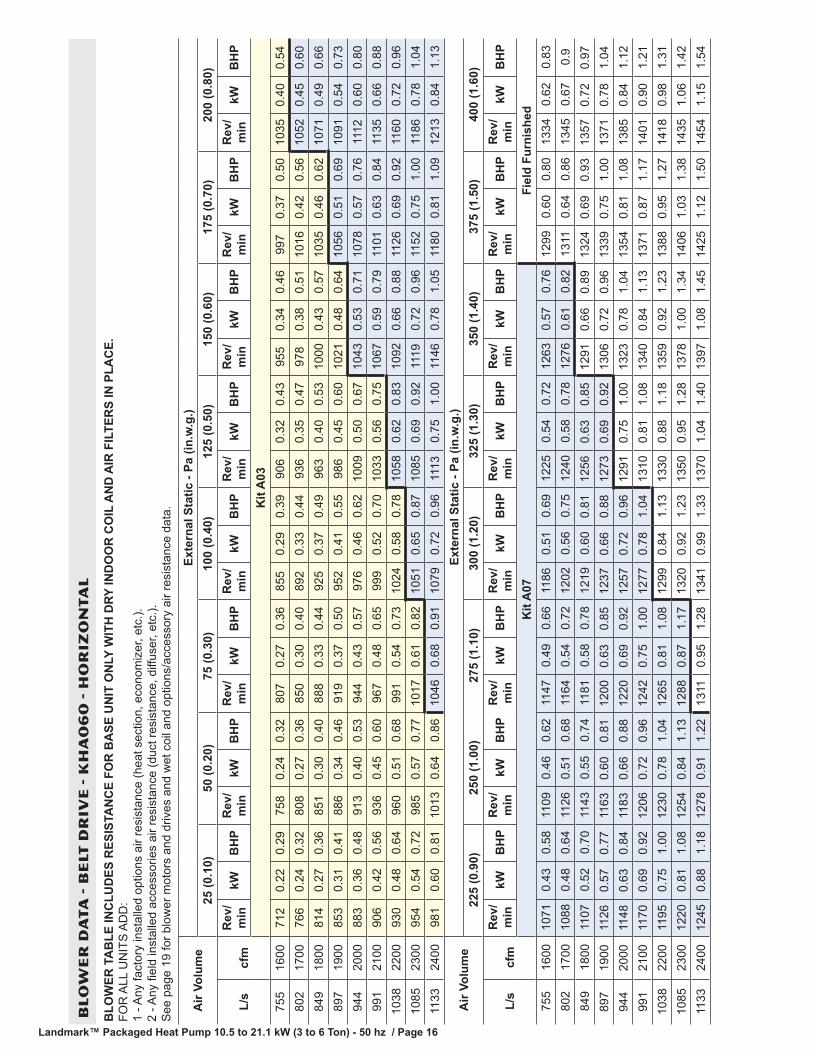
Landmark™ Packaged Heat Pump 10.5 to 21.1 kW (3 to 6 Ton) - 50 hz / Page 16 Landmark™ Packaged Heat Pump 10.5 to 21.1 kW (3 to 6 Ton) - 50 hz / Page 17
BL
OW
ER
DA
TA
- B
ELT
DR
IVE
- K
HA
06
0 -
HO
RIZ
ON
TA
L
BLO
WER
TA
BLE
INC
LUD
ES R
ESIS
TAN
CE
FOR
BA
SE U
NIT
ON
LY W
ITH
DRY
IND
OO
R C
OIL
AN
D A
IR F
ILTE
RS
IN P
LAC
E.
FOR
ALL
UN
ITS
AD
D:
1 - A
ny fa
ctor
y in
stal
led
optio
ns a
ir re
sist
ance
(hea
t sec
tion,
eco
nom
izer
, etc
.).
2 - A
ny fi
eld
inst
alle
d ac
cess
orie
s ai
r res
ista
nce
(duc
t res
ista
nce,
diff
user
, etc
.).
See
pag
e 19
for b
low
er m
otor
s an
d dr
ives
and
wet
coi
l and
opt
ions
/acc
esso
ry a
ir re
sist
ance
dat
a.
Air
Volu
me
Exte
rnal
Sta
tic -
Pa (i
n.w
.g.)
25 (0
.10)
50 (0
.20)
75 (0
.30)
100
(0.4
0)12
5 (0
.50)
150
(0.6
0)17
5 (0
.70)
200
(0.8
0)
L/s
cfm
Rev
/m
inkW
BH
PR
ev/
min
kWB
HP
Rev
/m
inkW
BH
PR
ev/
min
kWB
HP
Rev
/m
inkW
BH
PR
ev/
min
kWB
HP
Rev
/m
inkW
BH
PR
ev/
min
kWB
HP
Kit
A03
755
1600
712
0.22
0.29
758
0.24
0.32
807
0.27
0.36
855
0.29
0.39
906
0.32
0.43
955
0.34
0.46
997
0.37
0.50
1035
0.40
0.54
802
1700
766
0.24
0.32
808
0.27
0.36
850
0.30
0.40
892
0.33
0.44
936
0.35
0.47
978
0.38
0.51
1016
0.42
0.56
1052
0.45
0.60
849
1800
814
0.27
0.36
851
0.30
0.40
888
0.33
0.44
925
0.37
0.49
963
0.40
0.53
1000
0.43
0.57
1035
0.46
0.62
1071
0.49
0.66
897
1900
853
0.31
0.41
886
0.34
0.46
919
0.37
0.50
952
0.41
0.55
986
0.45
0.60
1021
0.48
0.64
1056
0.51
0.69
1091
0.54
0.73
944
2000
883
0.36
0.48
913
0.40
0.53
944
0.43
0.57
976
0.46
0.62
1009
0.50
0.67
1043
0.53
0.71
1078
0.57
0.76
1112
0.60
0.80
991
2100
906
0.42
0.56
936
0.45
0.60
967
0.48
0.65
999
0.52
0.70
1033
0.56
0.75
1067
0.59
0.79
1101
0.63
0.84
1135
0.66
0.88
1038
2200
930
0.48
0.64
960
0.51
0.68
991
0.54
0.73
1024
0.58
0.78
1058
0.62
0.83
1092
0.66
0.88
1126
0.69
0.92
1160
0.72
0.96
1085
2300
954
0.54
0.72
985
0.57
0.77
1017
0.61
0.82
1051
0.65
0.87
1085
0.69
0.92
1119
0.72
0.96
1152
0.75
1.00
1186
0.78
1.04
1133
2400
981
0.60
0.81
1013
0.64
0.86
1046
0.68
0.91
1079
0.72
0.96
1113
0.75
1.00
1146
0.78
1.05
1180
0.81
1.09
1213
0.84
1.13
Air
Volu
me
Exte
rnal
Sta
tic -
Pa (i
n.w
.g.)
225
(0.9
0)25
0 (1
.00)
275
(1.1
0)30
0 (1
.20)
325
(1.3
0)35
0 (1
.40)
375
(1.5
0)40
0 (1
.60)
L/s
cfm
Rev
/m
inkW
BH
PR
ev/
min
kWB
HP
Rev
/m
inkW
BH
PR
ev/
min
kWB
HP
Rev
/m
inkW
BH
PR
ev/
min
kWB
HP
Rev
/m
inkW
BH
PR
ev/
min
kWB
HP
Kit
A07
Fiel
d Fu
rnis
hed
755
1600
1071
0.43
0.58
1109
0.46
0.62
1147
0.49
0.66
1186
0.51
0.69
1225
0.54
0.72
1263
0.57
0.76
1299
0.60
0.80
1334
0.62
0.83
802
1700
1088
0.48
0.64
1126
0.51
0.68
1164
0.54
0.72
1202
0.56
0.75
1240
0.58
0.78
1276
0.61
0.82
1311
0.64
0.86
1345
0.67
0.9
849
1800
1107
0.52
0.70
1143
0.55
0.74
1181
0.58
0.78
1219
0.60
0.81
1256
0.63
0.85
1291
0.66
0.89
1324
0.69
0.93
1357
0.72
0.97
897
1900
1126
0.57
0.77
1163
0.60
0.81
1200
0.63
0.85
1237
0.66
0.88
1273
0.69
0.92
1306
0.72
0.96
1339
0.75
1.00
1371
0.78
1.04
944
2000
1148
0.63
0.84
1183
0.66
0.88
1220
0.69
0.92
1257
0.72
0.96
1291
0.75
1.00
1323
0.78
1.04
1354
0.81
1.08
1385
0.84
1.12
991
2100
1170
0.69
0.92
1206
0.72
0.96
1242
0.75
1.00
1277
0.78
1.04
1310
0.81
1.08
1340
0.84
1.13
1371
0.87
1.17
1401
0.90
1.21
1038
2200
1195
0.75
1.00
1230
0.78
1.04
1265
0.81
1.08
1299
0.84
1.13
1330
0.88
1.18
1359
0.92
1.23
1388
0.95
1.27
1418
0.98
1.31
1085
2300
1220
0.81
1.08
1254
0.84
1.13
1288
0.87
1.17
1320
0.92
1.23
1350
0.95
1.28
1378
1.00
1.34
1406
1.03
1.38
1435
1.06
1.42
1133
2400
1245
0.88
1.18
1278
0.91
1.22
1311
0.95
1.28
1341
0.99
1.33
1370
1.04
1.40
1397
1.08
1.45
1425
1.12
1.50
1454
1.15
1.54
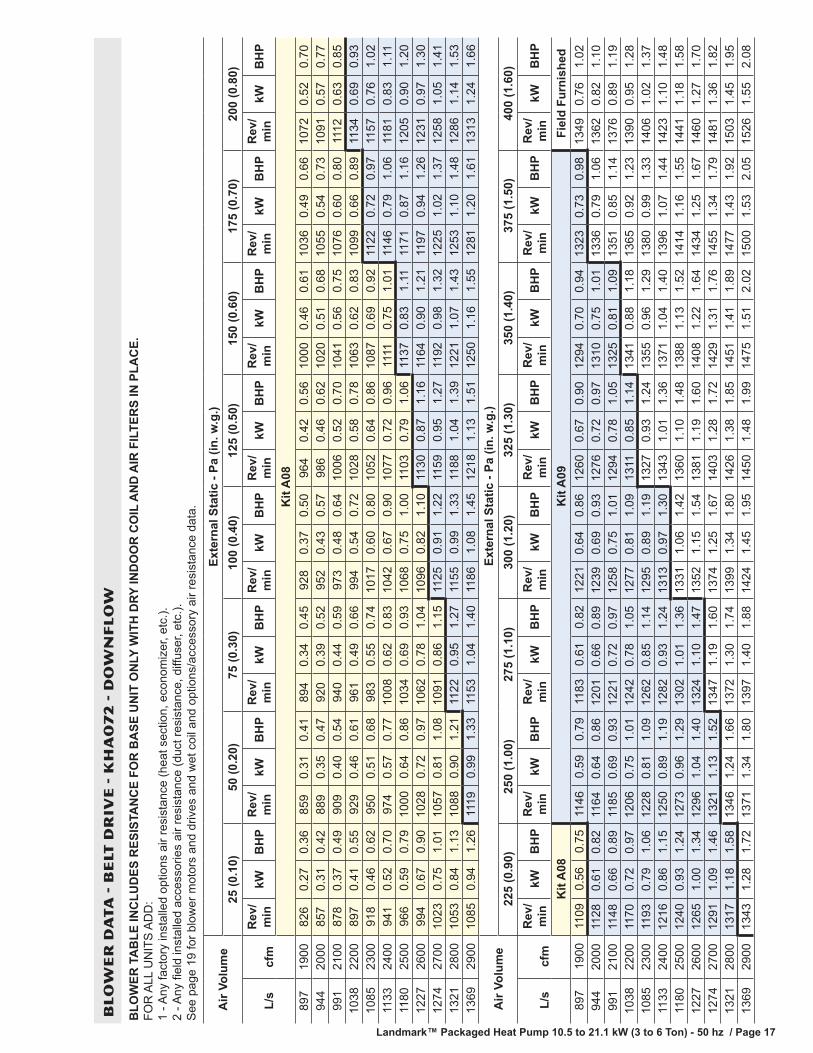
Landmark™ Packaged Heat Pump 10.5 to 21.1 kW (3 to 6 Ton) - 50 hz / Page 16 Landmark™ Packaged Heat Pump 10.5 to 21.1 kW (3 to 6 Ton) - 50 hz / Page 17
BL
OW
ER
DA
TA
- B
ELT
DR
IVE
- K
HA
07
2 -
DO
WN
FL
OW
BLO
WER
TA
BLE
INC
LUD
ES R
ESIS
TAN
CE
FOR
BA
SE U
NIT
ON
LY W
ITH
DRY
IND
OO
R C
OIL
AN
D A
IR F
ILTE
RS
IN P
LAC
E.
FOR
ALL
UN
ITS
AD
D:
1 - A
ny fa
ctor
y in
stal
led
optio
ns a
ir re
sist
ance
(hea
t sec
tion,
eco
nom
izer
, etc
.).
2 - A
ny fi
eld
inst
alle
d ac
cess
orie
s ai
r res
ista
nce
(duc
t res
ista
nce,
diff
user
, etc
.).
See
pag
e 19
for b
low
er m
otor
s an
d dr
ives
and
wet
coi
l and
opt
ions
/acc
esso
ry a
ir re
sist
ance
dat
a.
Air
Volu
me
Exte
rnal
Sta
tic -
Pa (i
n. w
.g.)
25 (0
.10)
50 (0
.20)
75 (0
.30)
100
(0.4
0)12
5 (0
.50)
150
(0.6
0)17
5 (0
.70)
200
(0.8
0)
L/s
cfm
Rev
/m
inkW
BH
PR
ev/
min
kWB
HP
Rev
/m
inkW
BH
PR
ev/
min
kWB
HP
Rev
/m
inkW
BH
PR
ev/
min
kWB
HP
Rev
/m
inkW
BH
PR
ev/
min
kWB
HP
Kit
A08
897
1900
826
0.27
0.36
859
0.31
0.41
894
0.34
0.45
928
0.37
0.50
964
0.42
0.56
1000
0.46
0.61
1036
0.49
0.66
1072
0.52
0.70
944
2000
857
0.31
0.42
889
0.35
0.47
920
0.39
0.52
952
0.43
0.57
986
0.46
0.62
1020
0.51
0.68
1055
0.54
0.73
1091
0.57
0.77
991
2100
878
0.37
0.49
909
0.40
0.54
940
0.44
0.59
973
0.48
0.64
1006
0.52
0.70
1041
0.56
0.75
1076
0.60
0.80
1112
0.63
0.85
1038
2200
897
0.41
0.55
929
0.46
0.61
961
0.49
0.66
994
0.54
0.72
1028
0.58
0.78
1063
0.62
0.83
1099
0.66
0.89
1134
0.69
0.93
1085
2300
918
0.46
0.62
950
0.51
0.68
983
0.55
0.74
1017
0.60
0.80
1052
0.64
0.86
1087
0.69
0.92
1122
0.72
0.97
1157
0.76
1.02
1133
2400
941
0.52
0.70
974
0.57
0.77
1008
0.62
0.83
1042
0.67
0.90
1077
0.72
0.96
1111
0.75
1.01
1146
0.79
1.06
1181
0.83
1.11
1180
2500
966
0.59
0.79
1000
0.64
0.86
1034
0.69
0.93
1068
0.75
1.00
1103
0.79
1.06
1137
0.83
1.11
1171
0.87
1.16
1205
0.90
1.20
1227
2600
994
0.67
0.90
1028
0.72
0.97
1062
0.78
1.04
1096
0.82
1.10
1130
0.87
1.16
1164
0.90
1.21
1197
0.94
1.26
1231
0.97
1.30
1274
2700
1023
0.75
1.01
1057
0.81
1.08
1091
0.86
1.15
1125
0.91
1.22
1159
0.95
1.27
1192
0.98
1.32
1225
1.02
1.37
1258
1.05
1.41
1321
2800
1053
0.84
1.13
1088
0.90
1.21
1122
0.95
1.27
1155
0.99
1.33
1188
1.04
1.39
1221
1.07
1.43
1253
1.10
1.48
1286
1.14
1.53
1369
2900
1085
0.94
1.26
1119
0.99
1.33
1153
1.04
1.40
1186
1.08
1.45
1218
1.13
1.51
1250
1.16
1.55
1281
1.20
1.61
1313
1.24
1.66
Air
Volu
me
Exte
rnal
Sta
tic -
Pa (i
n. w
.g.)
225
(0.9
0)25
0 (1
.00)
275
(1.1
0)30
0 (1
.20)
325
(1.3
0)35
0 (1
.40)
375
(1.5
0)40
0 (1
.60)
L/s
cfm
Rev
/m
inkW
BH
PR
ev/
min
kWB
HP
Rev
/m
inkW
BH
PR
ev/
min
kWB
HP
Rev
/m
inkW
BH
PR
ev/
min
kWB
HP
Rev
/m
inkW
BH
PR
ev/
min
kWB
HP
Kit
A08
Kit
A09
Fiel
d Fu
rnis
hed
897
1900
1109
0.56
0.75
1146
0.59
0.79
1183
0.61
0.82
1221
0.64
0.86
1260
0.67
0.90
1294
0.70
0.94
1323
0.73
0.98
1349
0.76
1.02
944
2000
1128
0.61
0.82
1164
0.64
0.86
1201
0.66
0.89
1239
0.69
0.93
1276
0.72
0.97
1310
0.75
1.01
1336
0.79
1.06
1362
0.82
1.10
991
2100
1148
0.66
0.89
1185
0.69
0.93
1221
0.72
0.97
1258
0.75
1.01
1294
0.78
1.05
1325
0.81
1.09
1351
0.85
1.14
1376
0.89
1.19
1038
2200
1170
0.72
0.97
1206
0.75
1.01
1242
0.78
1.05
1277
0.81
1.09
1311
0.85
1.14
1341
0.88
1.18
1365
0.92
1.23
1390
0.95
1.28
1085
2300
1193
0.79
1.06
1228
0.81
1.09
1262
0.85
1.14
1295
0.89
1.19
1327
0.93
1.24
1355
0.96
1.29
1380
0.99
1.33
1406
1.02
1.37
1133
2400
1216
0.86
1.15
1250
0.89
1.19
1282
0.93
1.24
1313
0.97
1.30
1343
1.01
1.36
1371
1.04
1.40
1396
1.07
1.44
1423
1.10
1.48
1180
2500
1240
0.93
1.24
1273
0.96
1.29
1302
1.01
1.36
1331
1.06
1.42
1360
1.10
1.48
1388
1.13
1.52
1414
1.16
1.55
1441
1.18
1.58
1227
2600
1265
1.00
1.34
1296
1.04
1.40
1324
1.10
1.47
1352
1.15
1.54
1381
1.19
1.60
1408
1.22
1.64
1434
1.25
1.67
1460
1.27
1.70
1274
2700
1291
1.09
1.46
1321
1.13
1.52
1347
1.19
1.60
1374
1.25
1.67
1403
1.28
1.72
1429
1.31
1.76
1455
1.34
1.79
1481
1.36
1.82
1321
2800
1317
1.18
1.58
1346
1.24
1.66
1372
1.30
1.74
1399
1.34
1.80
1426
1.38
1.85
1451
1.41
1.89
1477
1.43
1.92
1503
1.45
1.95
1369
2900
1343
1.28
1.72
1371
1.34
1.80
1397
1.40
1.88
1424
1.45
1.95
1450
1.48
1.99
1475
1.51
2.02
1500
1.53
2.05
1526
1.55
2.08

Landmark™ Packaged Heat Pump 10.5 to 21.1 kW (3 to 6 Ton) - 50 hz / Page 18
BL
OW
ER
DA
TA
- B
ELT
DR
IVE
- K
HA
07
2 -
HO
RIZ
ON
TA
L
BLO
WER
TA
BLE
INC
LUD
ES R
ESIS
TAN
CE
FOR
BA
SE U
NIT
ON
LY W
ITH
DRY
IND
OO
R C
OIL
AN
D A
IR F
ILTE
RS
IN P
LAC
E.
FOR
ALL
UN
ITS
AD
D:
1 - A
ny fa
ctor
y in
stal
led
optio
ns a
ir re
sist
ance
(hea
t sec
tion,
eco
nom
izer
, etc
.).
2 - A
ny fi
eld
inst
alle
d ac
cess
orie
s ai
r res
ista
nce
(duc
t res
ista
nce,
diff
user
, etc
.).
See
pag
e 19
for b
low
er m
otor
s an
d dr
ives
and
wet
coi
l and
opt
ions
/acc
esso
ry a
ir re
sist
ance
dat
a.
Air
Volu
me
Exte
rnal
Sta
tic -
Pa (i
n. w
.g.)
25 (0
.10)
50 (0
.20)
75 (0
.30)
100
(0.4
0)12
5 (0
.50)
150
(0.6
0)17
5 (0
.70)
200
(0.8
0)
L/s
cfm
Rev
/m
inkW
BH
PR
ev/
min
kWB
HP
Rev
/m
inkW
BH
PR
ev/
min
kWB
HP
Rev
/m
inkW
BH
PR
ev/
min
kWB
HP
Rev
/m
inkW
BH
PR
ev/
min
kWB
HP
Kit
A08
897
1900
853
0.31
0.41
886
0.34
0.46
919
0.37
0.50
952
0.41
0.55
986
0.45
0.60
1021
0.48
0.64
1056
0.51
0.69
1091
0.54
0.73
944
2000
883
0.36
0.48
913
0.40
0.53
944
0.43
0.57
976
0.46
0.62
1009
0.50
0.67
1043
0.53
0.71
1078
0.57
0.76
1112
0.60
0.80
991
2100
906
0.42
0.56
936
0.45
0.60
967
0.48
0.65
999
0.52
0.70
1033
0.56
0.75
1067
0.59
0.79
1101
0.63
0.84
1135
0.66
0.88
1038
2200
930
0.48
0.64
960
0.51
0.68
991
0.54
0.73
1024
0.58
0.78
1058
0.62
0.83
1092
0.66
0.88
1126
0.69
0.92
1160
0.72
0.96
1085
2300
954
0.54
0.72
985
0.57
0.77
1017
0.61
0.82
1051
0.65
0.87
1085
0.69
0.92
1119
0.72
0.96
1152
0.75
1.00
1186
0.78
1.04
1133
2400
981
0.60
0.81
1013
0.64
0.86
1046
0.68
0.91
1079
0.72
0.96
1113
0.75
1.00
1146
0.78
1.05
1180
0.81
1.09
1213
0.84
1.13
1180
2500
1010
0.68
0.91
1042
0.72
0.96
1075
0.75
1.00
1109
0.78
1.05
1142
0.81
1.09
1175
0.85
1.14
1207
0.88
1.18
1239
0.92
1.23
1227
2600
1040
0.75
1.01
1073
0.78
1.05
1106
0.82
1.10
1139
0.85
1.14
1171
0.89
1.19
1203
0.92
1.23
1235
0.95
1.28
1266
0.99
1.33
1274
2700
1072
0.82
1.10
1104
0.86
1.15
1137
0.90
1.20
1169
0.93
1.24
1201
0.96
1.29
1232
1.00
1.34
1263
1.04
1.40
1293
1.09
1.46
1321
2800
1105
0.90
1.21
1137
0.93
1.25
1168
0.97
1.30
1200
1.01
1.35
1231
1.04
1.40
1261
1.09
1.46
1291
1.13
1.52
1321
1.19
1.59
1369
2900
1138
0.98
1.32
1169
1.02
1.37
1200
1.06
1.42
1231
1.10
1.47
1261
1.14
1.53
1291
1.19
1.60
1321
1.24
1.66
1350
1.29
1.73
Air
Volu
me
Exte
rnal
Sta
tic -
Pa (i
n. w
.g.)
225
(0.9
0)25
0 (1
.00)
275
(1.1
0)30
0 (1
.20)
325
(1.3
0)35
0 (1
.40)
375
(1.5
0)40
0 (1
.60)
L/s
cfm
Rev
/m
inkW
BH
PR
ev/
min
kWB
HP
Rev
/m
inkW
BH
PR
ev/
min
kWB
HP
Rev
/m
inkW
BH
PR
ev/
min
kWB
HP
Rev
/m
inkW
BH
PR
ev/
min
kWB
HP
Kit
A09
Fiel
d Fu
rnis
hed
897
1900
1126
0.57
0.77
1163
0.60
0.81
1200
0.63
0.85
1237
0.66
0.88
1273
0.69
0.92
1306
0.72
0.96
1339
0.75
1.00
1371
0.78
1.04
944
2000
1148
0.63
0.84
1183
0.66
0.88
1220
0.69
0.92
1257
0.72
0.96
1291
0.75
1.00
1323
0.78
1.04
1354
0.81
1.08
1385
0.84
1.12
991
2100
1170
0.69
0.92
1206
0.72
0.96
1242
0.75
1.00
1277
0.78
1.04
1310
0.81
1.08
1340
0.84
1.13
1371
0.87
1.17
1401
0.90
1.21
1038
2200
1195
0.75
1.00
1230
0.78
1.04
1265
0.81
1.08
1299
0.84
1.13
1330
0.88
1.18
1359
0.92
1.23
1388
0.95
1.27
1418
0.98
1.31
1085
2300
1220
0.81
1.08
1254
0.84
1.13
1288
0.87
1.17
1320
0.92
1.23
1350
0.95
1.28
1378
1.00
1.34
1406
1.03
1.38
1435
1.06
1.42
1133
2400
1245
0.88
1.18
1278
0.91
1.22
1311
0.95
1.28
1341
0.99
1.33
1370
1.04
1.40
1397
1.08
1.45
1425
1.12
1.50
1454
1.15
1.54
1180
2500
1271
0.95
1.28
1303
0.99
1.33
1334
1.04
1.39
1363
1.08
1.45
1391
1.13
1.52
1418
1.17
1.57
1446
1.21
1.62
1474
1.24
1.66
1227
2600
1297
1.04
1.39
1328
1.08
1.45
1357
1.13
1.52
1385
1.18
1.58
1412
1.22
1.64
1439
1.27
1.70
1467
1.30
1.74
1495
1.33
1.78
1274
2700
1323
1.13
1.52
1353
1.18
1.58
1382
1.23
1.65
1409
1.28
1.72
1435
1.32
1.77
1462
1.36
1.82
1490
1.39
1.86
1517
1.42
1.90
1321
2800
1351
1.23
1.65
1380
1.28
1.72
1407
1.33
1.78
1434
1.38
1.85
1460
1.42
1.90
1486
1.45
1.95
1513
1.48
1.99
1541
1.51
2.02
1369
2900
1379
1.34
1.79
1407
1.39
1.86
1434
1.43
1.92
1460
1.48
1.98
1485
1.52
2.04
1511
1.55
2.08
1538
1.58
2.12
1565
1.60
2.15

Landmark� Packaged Heat Pump 10.5 to 21 kW (3 to 6 Ton) − 50hz / Page 19
BLOWER DATA
FACTORY INSTALLED BELT DRIVE KIT SPECIFICATIONS
Motor rev/min Range
Nominal Maximum Kit A01 Kit A02 Kit A03 Kit A05 Kit A06 Kit A07 Kit A08 Kit A09
1.5 kW(2 hp)
1.7 kW(2.3 hp)
561 − 842 621 − 931 694 − 1042 748 − 1122 893 − 1191 1010 − 1290 994 − 1326 1193 − 1524
*Using total air volume and system static pressure requirements determine from blower performance tables rev/min and motor kW required. Maximum usable kW of motorsfurnished are shown. If motors of comparable kW are used, be sure to keep within the service factor limitations outlined on the motor nameplate.
POWER EXHAUST FANS PERFORMANCE
Return Air SystemStatic Pressure
Air Volume Exhausted
T1PWRE10A T1PWRE10N
Low Medium High Low Medium High
Pa in. w.g. L/s cfm L/s cfm L/s cfm L/s cfm L/s cfm L/s cfm
0 0 510 1085 515 1085 510 1080 1525 3235 1625 3445 1705 3615
25 0.1 410 865 415 875 415 880 1280 2710 1395 2960 1475 3130
50 0.2 315 670 320 675 320 675 855 1810 1185 2510 1275 2700
75 0.3 235 495 230 490 230 485 865 1835 9985 2085 1090 2310
100 0.4 160 335 155 335 160 340 665 1405 790 1675 915 1935
125 0.5 95 200 100 210 120 250 440 935 595 1260 740 1570
150 0.6 35 75 65 135 115 240 185 390 390 825 360 760
OPTIONS / ACCESSORIES AIR RESISTANCE
Air Volume EconomizerWet Indoor Coil
Electric Heat036−048 060−072
L/s cfm Pa in. w.g. Pa in. w.g. Pa in. w.g. Pa in. w.g.
470 1000 10 0.04 5 0.02 2 0.01 7 0.03
565 1200 10 0.04 7 0.03 5 0.02 15 0.06
660 1400 10 0.04 10 0.04 7 0.03 22 0.09
755 1600 10 0.04 12 0.05 10 0.04 30 0.12
850 1800 12 0.05 15 0.06 12 0.05 37 0.15
945 2000 12 0.05 20 0.08 15 0.06 45 0.18
1040 2200 12 0.05 22 0.09 17 0.07 50 0.20
1130 2400 12 0.05 25 0.10 20 0.08 55 0.22
1225 2600 15 0.06 27 0.11 22 0.09 60 0.24
1320 2800 15 0.06 32 0.13 25 0.10 65 0.26
1415 3000 15 0.06 35 0.14 30 0.12 70 0.28

Landmark� Packaged Heat Pump 10.5 to 21 kW (3 to 6 Ton) − 50hz / Page 20
BLOWER DATA
CEILING DIFFUSERS AIR RESISTANCE
Air Volume
RTD9−65 Step-Down Diffuser FD9−65Flush
Diffuser
RTD11−95 Step-Down Diffuser FD11−95Flush
Diffuser2 EndsOpen
1 Side &2 Ends Open
All Ends &Sides Open
2 EndsOpen
1 Side & 2 Ends Open
All Ends &Sides Open
L/s cfm Pa in. w.g. Pa in. w.g. Pa in. w.g. Pa in. w.g. Pa in. w.g. Pa in. w.g. Pa in. w.g. Pa in. w.g.
470 1000 47 0.19 40 0.16 35 0.14 35 0.14 − − − − − − − − − − − − − − − − − − − − − − − −
565 1200 62 0.25 50 0.20 42 0.17 42 0.17 − − − − − − − − − − − − − − − − − − − − − − − −
660 1400 82 0.33 65 0.26 50 0.20 50 0.20 − − − − − − − − − − − − − − − − − − − − − − − −
755 1600 107 0.43 80 0.32 50 0.20 50 0.24 − − − − − − − − − − − − − − − − − − − − − − − −
850 1800 139 0.56 99 0.40 75 0.30 75 0.30 32 0.13 27 0.11 22 0.09 22 0.09
945 2000 182 0.73 124 0.50 90 0.36 90 0.36 37 0.15 32 0.13 27 0.11 25 0.10
1040 2200 236 0.95 157 0.63 109 0.44 109 0.44 45 0.18 37 0.15 30 0.12 30 0.12
1130 2400 − − − − − − − − − − − − − − − − − − − − − − − − 52 0.21 45 0.18 37 0.15 35 0.14
1225 2600 − − − − − − − − − − − − − − − − − − − − − − − − 60 0.24 52 0.21 45 0.18 42 0.17
1320 2800 − − − − − − − − − − − − − − − − − − − − − − − − 67 0.27 60 0.24 52 0.21 50 0.20
1415 3000 − − − − − − − − − − − − − − − − − − − − − − − − 80 0.32 72 0.29 62 0.25 62 0.25
CEILING DIFFUSER AIR THROW DATA
Air Volume 1 Effective Throw
Model No. RTD9−65 FD9−65
L/s cfm m ft. m ft.
470 1000 3 − 5 10 − 17 5 − 6 15 − 20
565 1200 3 − 5 11 − 18 5 − 7 16 − 22
660 1400 4 − 6 12 − 19 5 − 7 17 − 24
755 1600 4 − 6 12 − 20 5 − 8 18 − 25
850 1800 4 − 6 13 − 21 6 − 9 20 − 28
945 2000 4 − 7 14 − 23 6 − 9 21 − 29
1040 2200 5 − 8 16 − 25 7 − 9 22 − 30
Model No. RTD11−95 FD11−95
1225 2600 7 − 9 24 − 29 6 − 7 19 − 24
1320 2800 8 − 9 25 − 30 6 − 9 20 − 28
1415 3000 8 − 10 27 − 33 6 − 9 21 − 29
1 Effective throw based on terminal velocities of 23 m per minute ( 75 ft. per minute).
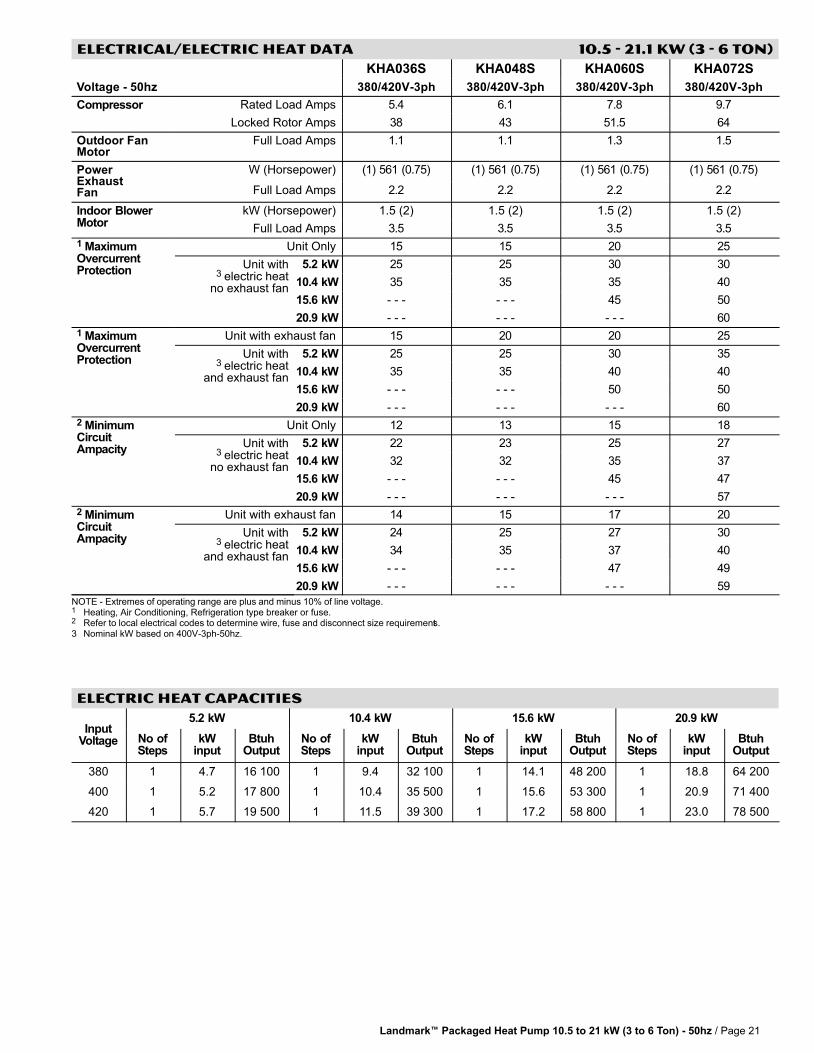
Landmark� Packaged Heat Pump 10.5 to 21 kW (3 to 6 Ton) − 50hz / Page 21
ELECTRICAL/ELECTRIC HEAT DATA 10.5 − 21.1 kW (3 − 6 Ton)
KHA036S KHA048S KHA060S KHA072S
Voltage − 50hz 380/420V−3ph 380/420V−3ph 380/420V−3ph 380/420V−3ph
Compressor Rated Load Amps 5.4 6.1 7.8 9.7
Locked Rotor Amps 38 43 51.5 64
Outdoor FanMotor
Full Load Amps 1.1 1.1 1.3 1.5
PowerExhaustFan
W (Horsepower) (1) 561 (0.75) (1) 561 (0.75) (1) 561 (0.75) (1) 561 (0.75)
Full Load Amps 2.2 2.2 2.2 2.2
Indoor BlowerMotor
kW (Horsepower) 1.5 (2) 1.5 (2) 1.5 (2) 1.5 (2)
Full Load Amps 3.5 3.5 3.5 3.5
1 MaximumOvercurrentProtection
Unit Only 15 15 20 25
Unit with3 electric heat
no exhaust fan
5.2 kW 25 25 30 30
10.4 kW 35 35 35 40
15.6 kW − − − − − − 45 50
20.9 kW − − − − − − − − − 60
1 MaximumOvercurrentProtection
Unit with exhaust fan 15 20 20 25
Unit with3 electric heat
and exhaust fan
5.2 kW 25 25 30 35
10.4 kW 35 35 40 40
15.6 kW − − − − − − 50 50
20.9 kW − − − − − − − − − 60
2 MinimumCircuitAmpacity
Unit Only 12 13 15 18
Unit with3 electric heat
no exhaust fan
5.2 kW 22 23 25 27
10.4 kW 32 32 35 37
15.6 kW − − − − − − 45 47
20.9 kW − − − − − − − − − 57
2 MinimumCircuitAmpacity
Unit with exhaust fan 14 15 17 20
Unit with3 electric heat
and exhaust fan
5.2 kW 24 25 27 30
10.4 kW 34 35 37 40
15.6 kW − − − − − − 47 49
20.9 kW − − − − − − − − − 59
NOTE�− Extremes�of�operating�range�are�plus�and�minus�10%�of�line�voltage.1 Heating, Air Conditioning, Refrigeration type breaker or fuse.2 Refer�to�local�electrical�codes�to�determine�wire,�fuse�and�disconnect�size�requirements.3 Nominal kW based on 400V−3ph−50hz.
ELECTRIC HEAT CAPACITIES
InputVoltage
5.2 kW 10.4 kW 15.6 kW 20.9 kW
No ofSteps
kWinput
BtuhOutput
No ofSteps
kWinput
BtuhOutput
No ofSteps
kWinput
BtuhOutput
No ofSteps
kWinput
BtuhOutput
380 1 4.7 16 100 1 9.4 32 100 1 14.1 48 200 1 18.8 64 200
400 1 5.2 17 800 1 10.4 35 500 1 15.6 53 300 1 20.9 71 400
420 1 5.7 19 500 1 11.5 39 300 1 17.2 58 800 1 23.0 78 500

Landmark� Packaged Heat Pump 10.5 to 21 kW (3 to 6 Ton) − 50hz / Page 22
UNIT CLEARANCES − mm (INCHES)
B
D
C
A
OUTDOOR AIRHOOD
1 Unit ClearanceA B C D
TopClearancemm in. mm in. mm in. mm in.
Service Clearance 914 36 914 36 914 36 914 36Unobstructed
Minimum Operation Clearance 914 36 914 36 914 36 914 36
NOTE − Entire perimeter of unit base requires support when elevated above the mounting surface.1 Service Clearance − Required for removal of serviceable parts.
Minimum Operation Clearance − Required clearance for proper unit operation.
OUTDOOR SOUND DATA
1 UnitModel No.
OperatingMode
Octave Band Sound Power Levels dBA, re 10−12 WattsCenter Frequency − HZ
SoundRating
Number(dB)125 250 500 1000 2000 4000 8000
036 and 048Cooling 63 66 70 71 68 62 53 75
Heating 63 66 71 70 68 62 54 75
060Cooling 67 72 77 76 73 68 61 82
Heating 70 72 77 76 73 69 60 82
072Cooling 67 75 78 78 75 68 59 83
Heating 69 77 79 80 76 69 61 84
Note The octave power sound data does not include tonal correction.1 Tested according to AHRI Standard 270-2008 test conditions and ANSI Standard S1.32-1981.
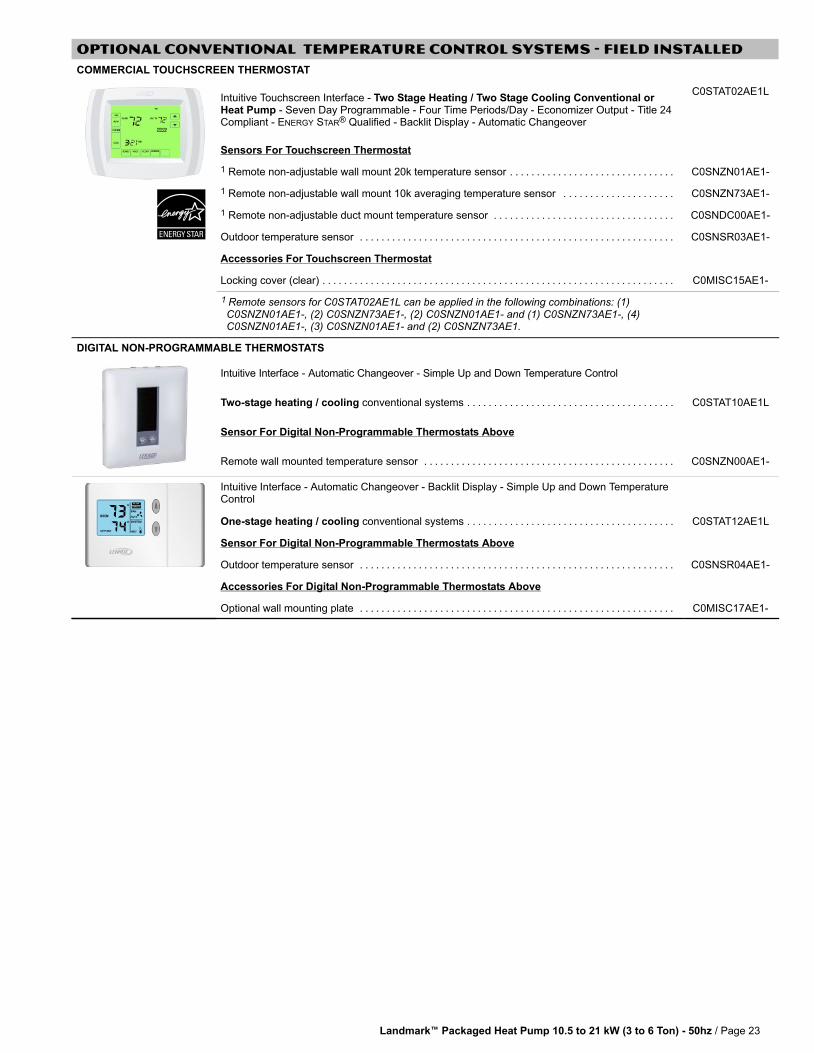
Landmark� Packaged Heat Pump 10.5 to 21 kW (3 to 6 Ton) − 50hz / Page 23
OPTIONAL CONVENTIONAL TEMPERATURE CONTROL SYSTEMS − FIElD INSTALLED
COMMERCIAL TOUCHSCREEN THERMOSTAT
Intuitive Touchscreen Interface − Two Stage Heating / Two Stage Cooling Conventional orHeat Pump − Seven Day Programmable − Four Time Periods/Day − Economizer Output − Title 24Compliant − ENERGY STAR® Qualified − Backlit Display − Automatic Changeover
C0STAT02AE1L
Sensors For Touchscreen Thermostat
1 Remote non−adjustable wall mount 20k temperature sensor . . . . . . . . . . . . . . . . . . . . . . . . . . . . . . . C0SNZN01AE1−
1 Remote non−adjustable wall mount 10k averaging temperature sensor . . . . . . . . . . . . . . . . . . . . . C0SNZN73AE1−
1 Remote non−adjustable duct mount temperature sensor . . . . . . . . . . . . . . . . . . . . . . . . . . . . . . . . . . C0SNDC00AE1−
Outdoor temperature sensor . . . . . . . . . . . . . . . . . . . . . . . . . . . . . . . . . . . . . . . . . . . . . . . . . . . . . . . . . . . C0SNSR03AE1−
Accessories For Touchscreen Thermostat
Locking cover (clear) . . . . . . . . . . . . . . . . . . . . . . . . . . . . . . . . . . . . . . . . . . . . . . . . . . . . . . . . . . . . . . . . . . C0MISC15AE1−
1 Remote sensors for C0STAT02AE1L can be applied in the following combinations: (1) C0SNZN01AE1−, (2) C0SNZN73AE1−, (2) C0SNZN01AE1− and (1) C0SNZN73AE1−, (4) C0SNZN01AE1−, (3) C0SNZN01AE1− and (2) C0SNZN73AE1.
DIGITAL NON−PROGRAMMABLE THERMOSTATS
Intuitive Interface − Automatic Changeover − Simple Up and Down Temperature Control
Two−stage heating / cooling conventional systems . . . . . . . . . . . . . . . . . . . . . . . . . . . . . . . . . . . . . . . C0STAT10AE1L
Sensor For Digital Non−Programmable Thermostats Above
Remote wall mounted temperature sensor . . . . . . . . . . . . . . . . . . . . . . . . . . . . . . . . . . . . . . . . . . . . . . . C0SNZN00AE1−
Intuitive Interface − Automatic Changeover − Backlit Display − Simple Up and Down TemperatureControl
One−stage heating / cooling conventional systems . . . . . . . . . . . . . . . . . . . . . . . . . . . . . . . . . . . . . . . C0STAT12AE1L
Sensor For Digital Non−Programmable Thermostats Above
Outdoor temperature sensor . . . . . . . . . . . . . . . . . . . . . . . . . . . . . . . . . . . . . . . . . . . . . . . . . . . . . . . . . . . C0SNSR04AE1−
Accessories For Digital Non−Programmable Thermostats Above
Optional wall mounting plate . . . . . . . . . . . . . . . . . . . . . . . . . . . . . . . . . . . . . . . . . . . . . . . . . . . . . . . . . . . C0MISC17AE1−
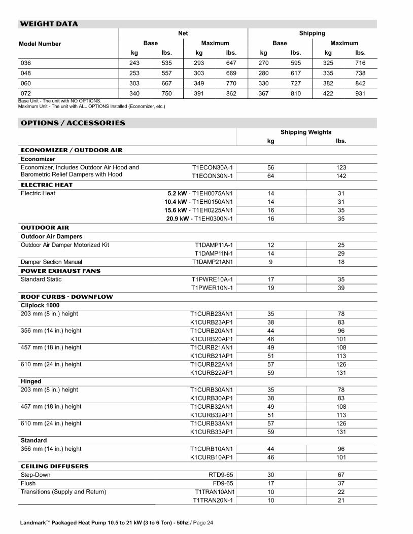
Landmark� Packaged Heat Pump 10.5 to 21 kW (3 to 6 Ton) − 50hz / Page 24
WEIGHT DATA
Model Number
Net Shipping
Base Maximum Base Maximum
kg lbs. kg lbs. kg lbs. kg lbs.
036 243 535 293 647 270 595 325 716
048 253 557 303 669 280 617 335 738
060 303 667 349 770 330 727 382 842
072 340 750 391 862 367 810 422 931Base Unit − The unit with NO OPTIONS.Maximum Unit − The unit with ALL OPTIONS Installed (Economizer, etc.)
OPTIONs / ACCESSORIES
Shipping Weights
kg lbs.
ECONOMIZER / OUTDOOR AIR
Economizer
Economizer, Includes Outdoor Air Hood andBarometric Relief Dampers with Hood
T1ECON30A−1 56 123
T1ECON30N−1 64 142
ELECTRIC HEAT
Electric Heat 5.2 kW − T1EH0075AN1 14 31
10.4 kW − T1EH0150AN1 14 31
15.6 kW − T1EH0225AN1 16 35
20.9 kW − T1EH0300N−1 16 35
OUTDOOR AIR
Outdoor Air Dampers
Outdoor Air Damper Motorized Kit T1DAMP11A−1 12 25
T1DAMP11N−1 14 29
Damper Section Manual T1DAMP21AN1 9 18
POWER EXHAUST FANS
Standard Static T1PWRE10A−1 17 35
T1PWER10N−1 19 39
ROOF CURBS − DOWNFLOW
Cliplock 1000
203 mm (8 in.) height T1CURB23AN1 35 78
K1CURB23AP1 38 83
356 mm (14 in.) height T1CURB20AN1 44 96
K1CURB20AP1 46 101
457 mm (18 in.) height T1CURB21AN1 49 108
K1CURB21AP1 51 113
610 mm (24 in.) height T1CURB22AN1 57 126
K1CURB22AP1 59 131
Hinged
203 mm (8 in.) height T1CURB30AN1 35 78
K1CURB30AP1 38 83
457 mm (18 in.) height T1CURB32AN1 49 108
K1CURB32AP1 51 113
610 mm (24 in.) height T1CURB33AN1 57 126
K1CURB33AP1 59 131
Standard
356 mm (14 in.) height T1CURB10AN1 44 96
K1CURB10AP1 46 101
CEILING DIFFUSERS
Step−Down RTD9−65 30 67
Flush FD9−65 17 37
Transitions (Supply and Return) T1TRAN10AN1 10 22
T1TRAN20N−1 10 21
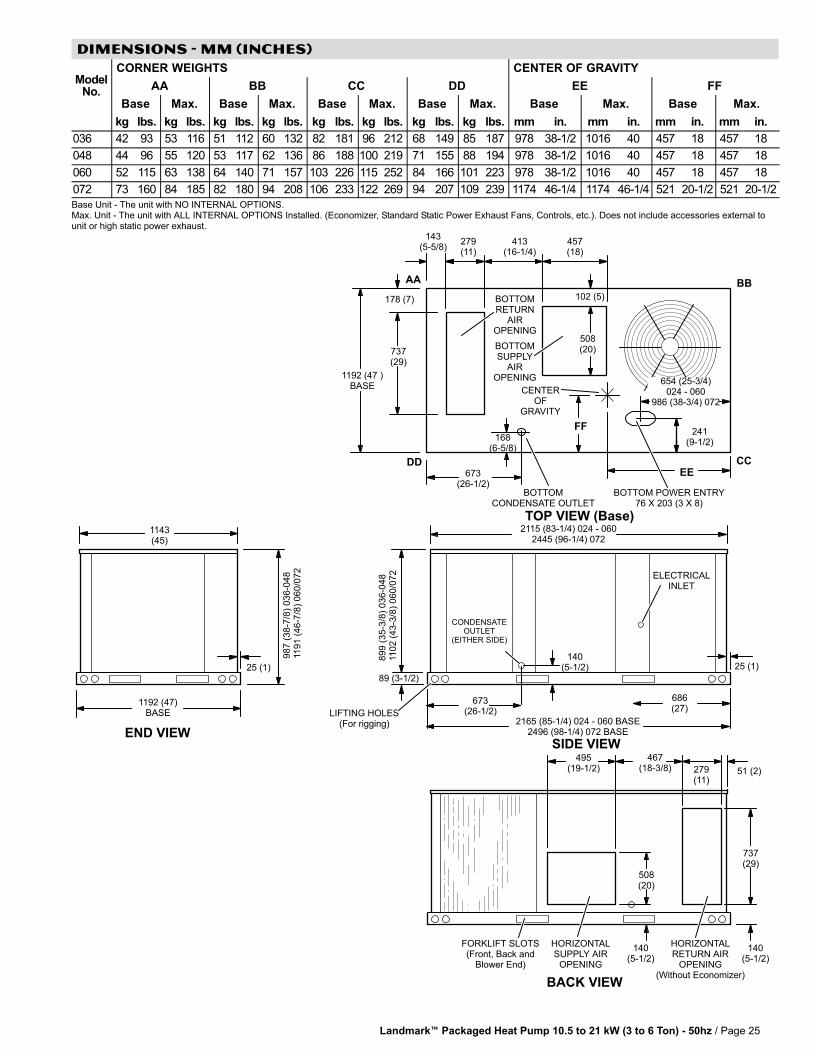
Landmark� Packaged Heat Pump 10.5 to 21 kW (3 to 6 Ton) − 50hz / Page 25
DIMENSIONS − MM (INCHES)
ModelNo.
CORNER WEIGHTS CENTER OF GRAVITY
AA BB CC DD EE FF
Base Max. Base Max. Base Max. Base Max. Base Max. Base Max.
kg lbs. kg lbs. kg lbs. kg lbs. kg lbs. kg lbs. kg lbs. kg lbs. mm in. mm in. mm in. mm in.
036 42 93 53 116 51 112 60 132 82 181 96 212 68 149 85 187 978 38−1/2 1016 40 457 18 457 18
048 44 96 55 120 53 117 62 136 86 188 100 219 71 155 88 194 978 38−1/2 1016 40 457 18 457 18
060 52 115 63 138 64 140 71 157 103 226 115 252 84 166 101 223 978 38−1/2 1016 40 457 18 457 18
072 73 160 84 185 82 180 94 208 106 233 122 269 94 207 109 239 1174 46−1/4 1174 46−1/4 521 20−1/2 521 20−1/2
Base Unit − The unit with NO INTERNAL OPTIONS.Max. Unit − The unit with ALL INTERNAL OPTIONS Installed. (Economizer, Standard Static Power Exhaust Fans, Controls, etc.). Does not include accessories external tounit or high static power exhaust.
1143(45)
END VIEW
25 (1)
1192 (47)BASE
987 (
38−7
/8)
036−0
48
1191 (
46−7
/8)
060/0
72
CONDENSATEOUTLET
(EITHER SIDE)
89 (3−1/2)
673(26−1/2)
140(5−1/2)
DD CC
BBAA
FF
EE
279(11)
413(16−1/4)
457(18)
508(20)
102 (5)
1192 (47 )BASE
BOTTOMSUPPLY
AIROPENING
TOP VIEW (Base)
CENTEROF
GRAVITY
241(9−1/2)
168(6−5/8)
673(26−1/2)
143(5−5/8)
737(29)
178 (7) BOTTOMRETURN
AIROPENING
BOTTOMCONDENSATE OUTLET
BOTTOM POWER ENTRY76 X 203 (3 X 8)
LIFTING HOLES(For rigging)
SIDE VIEW
686(27)
ELECTRICALINLET
25 (1)
467(18−3/8)
495(19−1/2)
140(5−1/2)
FORKLIFT SLOTS(Front, Back and
Blower End)
HORIZONTALRETURN AIR
OPENING(Without Economizer)
HORIZONTALSUPPLY AIR
OPENING
51 (2)279(11)
737(29)
508(20)
140(5−1/2)
BACK VIEW
899 (
35−3
/8)
036−0
48
1102 (
43−3
/8)
060/0
72
2115 (83−1/4) 024 − 0602445 (96−1/4) 072
2165 (85−1/4) 024 − 060 BASE2496 (98−1/4) 072 BASE
654 (25−3/4)024 − 060
986 (38−3/4) 072

Landmark� Packaged Heat Pump 10.5 to 21 kW (3 to 6 Ton) − 50hz / Page 26
ACCESSORY DIMENSIONS − MM (INCHES)
OUTDOOR AIR HOOD DETAIL FOR OPTIONAL ECONOMIZER AND BAROMETRIC RELIEF DAMPERS(Downflow Applications)
SIDE VIEW
OUTDOOR AIR HOOD(Furnished with Economizer)
305(12)
BAROMETRIC RELIEF HOOD(Furnished with Economizer)
298 (11−3/4) 036−048400 (15−3/4) 060 and 072
19 (3/4)
305(12)
32(1−1/4)
B
C 775(30−1/2)
64(2−1/2)
25 (1)
A
838(33)
32(1−1/4)
38(1−1/2)
10 (3/8)
BAROMETRIC RELIEF HOOD FOR ECONOMIZER(Furnished)
OUTDOOR AIR HOOD FOR ECONOMIZER(Furnished)
64(2−1/2)
ModelNo.
A B C
mm in. mm in. mm in.
036, 048 489 19−1/4 330 13 298 11−3/4
060, 072 591 23−1/4 432 17 400 15−3/4
419(16−1/2)
889 (35)036−048
1092 (43)060 and 072
OUTDOOR AIRDAMPER HOOD
889(35)
343(13−1/2)
267(10−1/2)
SIDE VIEW
OUTDOOR AIR DAMPER HOOD DETAIL FOR OPTIONAL MANUAL OR MOTORIZED OUTDOOR AIR DAMPERS(Downflow or Horizontal Applications)
267(10−1/2)
OUTDOOR AIRDAMPER HOOD
(Furnished)
OPTIONALOUTDOOR
AIR DAMPERSAND PANEL
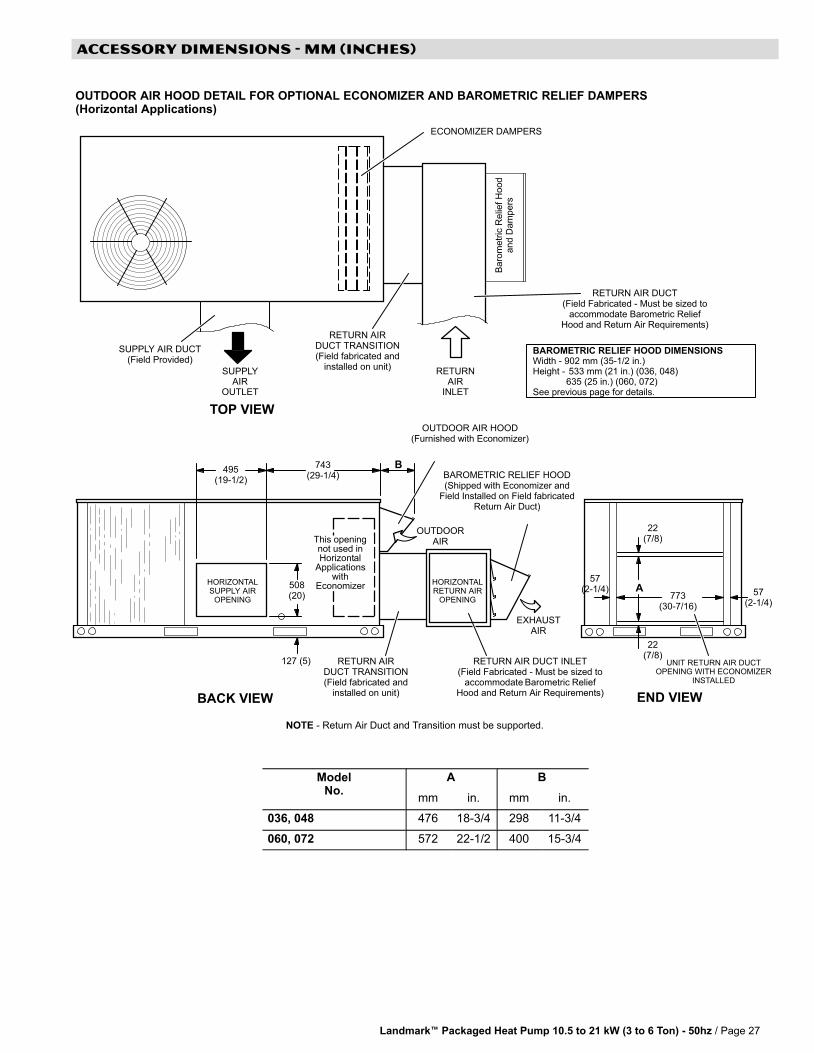
Landmark� Packaged Heat Pump 10.5 to 21 kW (3 to 6 Ton) − 50hz / Page 27
ACCESSORY DIMENSIONS − mm (INCHES)
RETURN AIR DUCT INLET(Field Fabricated − Must be sized to
accommodate Barometric ReliefHood and Return Air Requirements)
57(2−1/4)
508(20)
127 (5)
HORIZONTALSUPPLY AIR
OPENING
495(19−1/2)
SUPPLY AIR DUCT(Field Provided)
RETURN AIR DUCT(Field Fabricated − Must be sized to
accommodate Barometric ReliefHood and Return Air Requirements)
BAROMETRIC RELIEF HOOD(Shipped with Economizer and
Field Installed on Field fabricatedReturn Air Duct)
UNIT RETURN AIR DUCTOPENING WITH ECONOMIZER
INSTALLED
RETURN AIRDUCT TRANSITION(Field fabricated and
installed on unit)
743(29−1/4)
B
OUTDOOR AIR HOOD(Furnished with Economizer)
773(30−7/16)
22(7/8)
A
TOP VIEW
BACK VIEW END VIEW
EXHAUSTAIR
OUTDOORAIR
22(7/8)
57(2−1/4)
OUTDOOR AIR HOOD DETAIL FOR OPTIONAL ECONOMIZER AND BAROMETRIC RELIEF DAMPERS(Horizontal Applications)
NOTE − Return Air Duct and Transition must be supported.
This openingnot used inHorizontal
Applicationswith
Economizer
Baro
metr
ic R
elie
f H
ood
and D
am
pers
HORIZONTALRETURN AIR
OPENING
RETURN AIRDUCT TRANSITION(Field fabricated and
installed on unit)
BAROMETRIC RELIEF HOOD DIMENSIONSWidth − 902 mm (35−1/2 in.)Height − 533 mm (21 in.) (036, 048)
635 (25 in.) (060, 072)See previous page for details.
ECONOMIZER DAMPERS
RETURNAIR
INLET
SUPPLYAIR
OUTLET
ModelNo.
A B
mm in. mm in.
036, 048 476 18−3/4 298 11−3/4
060, 072 572 22−1/2 400 15−3/4
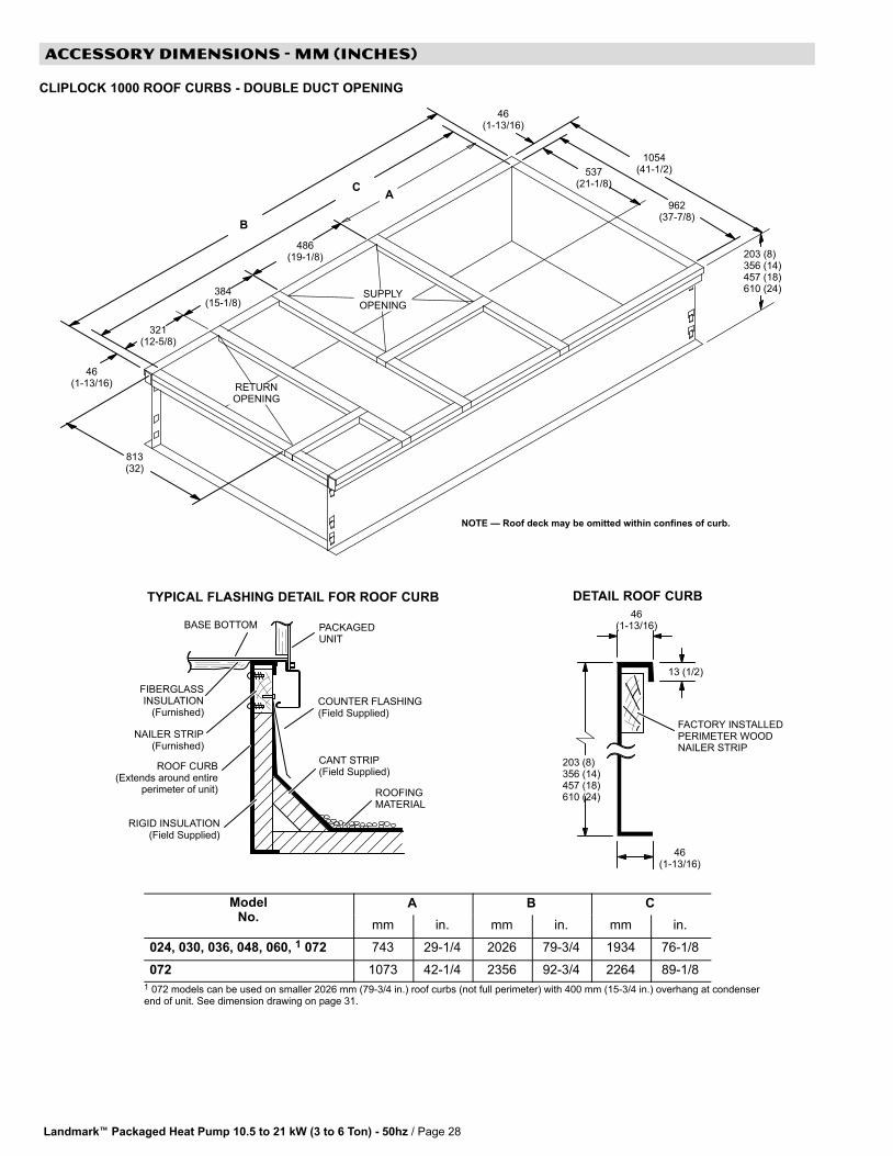
Landmark� Packaged Heat Pump 10.5 to 21 kW (3 to 6 Ton) − 50hz / Page 28
ACCESSORY DIMENSIONS − MM (INCHES)
CLIPLOCK 1000 ROOF CURBS − DOUBLE DUCT OPENING
TYPICAL FLASHING DETAIL FOR ROOF CURB
ROOF CURB(Extends around entire
perimeter of unit)
FIBERGLASSINSULATION
(Furnished)COUNTER FLASHING(Field Supplied)
BASE BOTTOM
RIGID INSULATION(Field Supplied)
ROOFINGMATERIAL
CANT STRIP(Field Supplied)
PACKAGEDUNIT
NAILER STRIP(Furnished)
DETAIL ROOF CURB
203 (8)356 (14)457 (18)610 (24)
FACTORY INSTALLEDPERIMETER WOODNAILER STRIP
46(1−13/16)
RETURNOPENING
SUPPLYOPENING
203 (8)356 (14)457 (18)610 (24)
321(12−5/8)
1054(41−1/2)537
(21−1/8)
486(19−1/8)
384(15−1/8)
813(32)
962(37−7/8)
46(1−13/16)
46(1−13/16)
46(1−13/16)
13 (1/2)
NOTE � Roof deck may be omitted within confines of curb.
B
CA
ModelNo.
A B C
mm in. mm in. mm in.
024, 030, 036, 048, 060, 1 072 743 29−1/4 2026 79−3/4 1934 76−1/8
072 1073 42−1/4 2356 92−3/4 2264 89−1/8
1 072 models can be used on smaller 2026 mm (79−3/4 in.) roof curbs (not full perimeter) with 400 mm (15−3/4 in.) overhang at condenserend of unit. See dimension drawing on page 31.
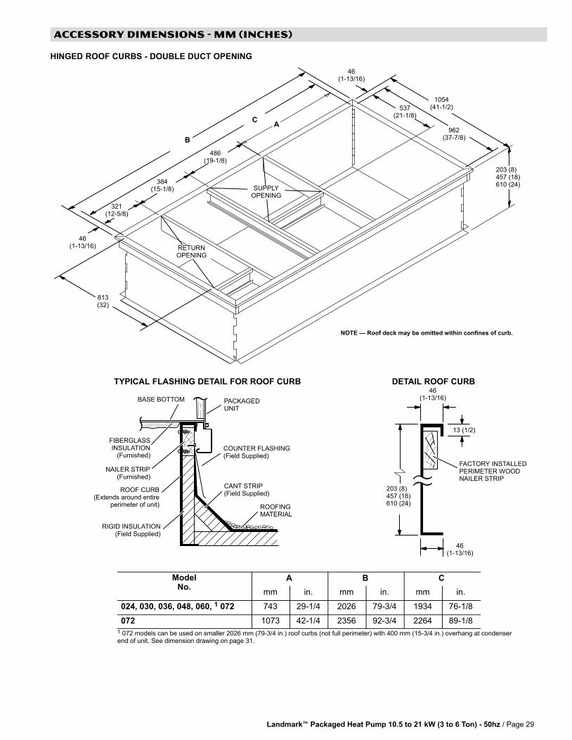
Landmark� Packaged Heat Pump 10.5 to 21 kW (3 to 6 Ton) − 50hz / Page 29
ACCESSORY DIMENSIONS − MM (INCHES)
HINGED ROOF CURBS − DOUBLE DUCT OPENING
TYPICAL FLASHING DETAIL FOR ROOF CURB
ROOF CURB(Extends around entire
perimeter of unit)
FIBERGLASSINSULATION
(Furnished)COUNTER FLASHING(Field Supplied)
BASE BOTTOM
RIGID INSULATION(Field Supplied)
ROOFINGMATERIAL
CANT STRIP(Field Supplied)
PACKAGEDUNIT
NAILER STRIP(Furnished)
DETAIL ROOF CURB
203 (8)457 (18)610 (24)
FACTORY INSTALLEDPERIMETER WOODNAILER STRIP
46(1−13/16)
321(12−5/8)
1054(41−1/2)537
(21−1/8)
486(19−1/8)
384(15−1/8)
813(32)
962(37−7/8)
46(1−13/16)
46(1−13/16)
46(1−13/16)
13 (1/2)
203 (8)457 (18)610 (24)
RETURNOPENING
SUPPLYOPENING
NOTE � Roof deck may be omitted within confines of curb.
CA
B
ModelNo.
A B C
mm in. mm in. mm in.
024, 030, 036, 048, 060, 1 072 743 29−1/4 2026 79−3/4 1934 76−1/8
072 1073 42−1/4 2356 92−3/4 2264 89−1/8
1 072 models can be used on smaller 2026 mm (79−3/4 in.) roof curbs (not full perimeter) with 400 mm (15−3/4 in.) overhang at condenserend of unit. See dimension drawing on page 31.
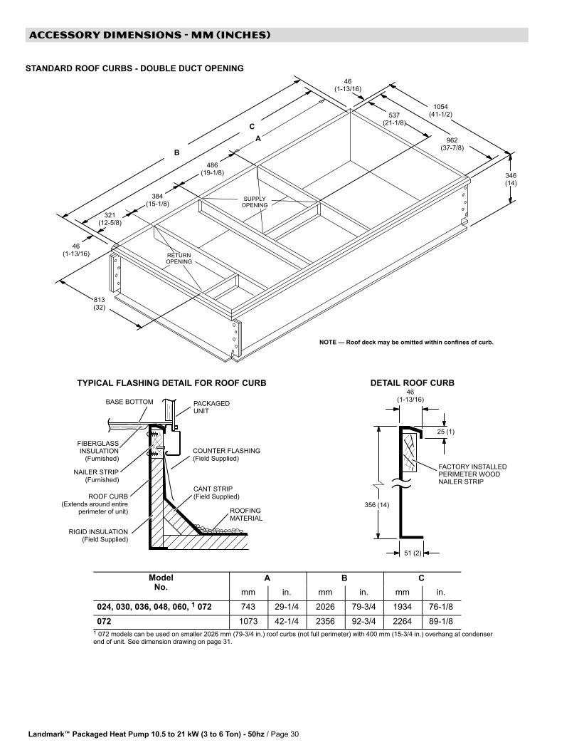
Landmark� Packaged Heat Pump 10.5 to 21 kW (3 to 6 Ton) − 50hz / Page 30
ACCESSORY DIMENSIONS − MM (INCHES)
STANDARD ROOF CURBS − DOUBLE DUCT OPENING
TYPICAL FLASHING DETAIL FOR ROOF CURB
ROOF CURB(Extends around entire
perimeter of unit)
FIBERGLASSINSULATION
(Furnished)COUNTER FLASHING(Field Supplied)
BASE BOTTOM
RIGID INSULATION(Field Supplied)
ROOFINGMATERIAL
CANT STRIP(Field Supplied)
PACKAGEDUNIT
NAILER STRIP(Furnished)
46(1−13/16)
46(1−13/16)
DETAIL ROOF CURB
356 (14)
25 (1)
FACTORY INSTALLEDPERIMETER WOODNAILER STRIP
51 (2)
321(12−5/8)
1054(41−1/2)537
(21−1/8)
SUPPLYOPENING
486(19−1/8)
384(15−1/8)
RETURNOPENING
813(32)
346(14)
962(37−7/8)
46(1−13/16)
NOTE � Roof deck may be omitted within confines of curb.
B
C
A
ModelNo.
A B C
mm in. mm in. mm in.
024, 030, 036, 048, 060, 1 072 743 29−1/4 2026 79−3/4 1934 76−1/8
072 1073 42−1/4 2356 92−3/4 2264 89−1/8
1 072 models can be used on smaller 2026 mm (79−3/4 in.) roof curbs (not full perimeter) with 400 mm (15−3/4 in.) overhang at condenserend of unit. See dimension drawing on page 31.

Landmark� Packaged Heat Pump 10.5 to 21 kW (3 to 6 Ton) − 50hz / Page 31
ACCESSORY DIMENSIONS − INCHES (MM)
072 MODELS − SHOWING OVERHANG ON SMALLER 2026 MM (79−3/4 INCH) LENGTH ROOF CURBS(Not Full Perimeter)
SIDE VIEW
ROOF CURB
686(2/3/4)
2026(79−3/4)
400(15−3/4)
RE
TU
RN
OP
EN
ING
305(12) 800
(31−1/2)
203 (8)
470(18−1/2)
521(20−1/2)
203 (8)
RETURN TRANSITION
SUPPLY TRANSITION
TRANSITIONS
521(21−1/8)
SUPPLYOPENING
813(32)
T1TRAN10AN−1 − FOR 457 MM (18 INCH) DUCT
T1TRAN10AN−1 − FOR 457 MM (18 INCH) DUCT
321(12−5/8)
486(19−1/8)
38 mm (1−1/2 inch) T1TRAN10AN−1
38 mm (1−1/2 inch) T1TRAN10AN−1
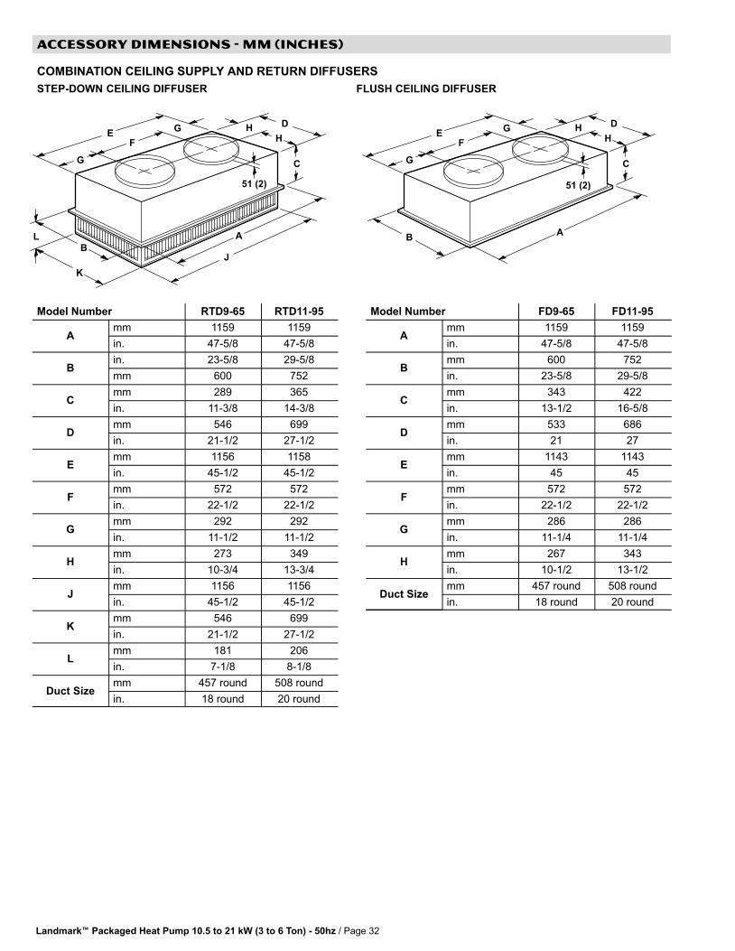
Landmark� Packaged Heat Pump 10.5 to 21 kW (3 to 6 Ton) − 50hz / Page 32
ACCESSORY DIMENSIONS − MM (INCHES)
COMBINATION CEILING SUPPLY AND RETURN DIFFUSERS
STEP-DOWN CEILING DIFFUSER FLUSH CEILING DIFFUSER
L A
J
C
HH
DG
G
FE
B
K
51 (2)
A
C
HH
DG
G
FE
B
51 (2)
Model Number RTD9−65 RTD11−95
Amm 1159 1159
in. 47−5/8 47−5/8
Bin. 23−5/8 29−5/8
mm 600 752
Cmm 289 365
in. 11−3/8 14−3/8
Dmm 546 699
in. 21−1/2 27−1/2
Emm 1156 1158
in. 45−1/2 45−1/2
Fmm 572 572
in. 22−1/2 22−1/2
Gmm 292 292
in. 11−1/2 11−1/2
Hmm 273 349
in. 10−3/4 13−3/4
Jmm 1156 1156
in. 45−1/2 45−1/2
Kmm 546 699
in. 21−1/2 27−1/2
Lmm 181 206
in. 7−1/8 8−1/8
Duct Sizemm 457 round 508 round
in. 18 round 20 round
Model Number FD9−65 FD11−95
Amm 1159 1159
in. 47−5/8 47−5/8
Bmm 600 752
in. 23−5/8 29−5/8
Cmm 343 422
in. 13−1/2 16−5/8
Dmm 533 686
in. 21 27
Emm 1143 1143
in. 45 45
Fmm 572 572
in. 22−1/2 22−1/2
Gmm 286 286
in. 11−1/4 11−1/4
Hmm 267 343
in. 10−1/2 13−1/2
Duct Sizemm 457 round 508 round
in. 18 round 20 round


Visit us at www.lennox.com
For the latest technical information, www.lennoxcommercial.com
Contact us at 1−800−4−LENNOX
NOTE − Due to Lennox’ ongoing commitment to quality, Specifications, Ratings and Dimensions subject to change without notice and without incurring liability.Improper installation, adjustment, alteration, service or maintenance can cause property damage or personal injury.Installation and service must be performed by a qualified installer and servicing agency. ©2010 Lennox Industries Inc.