E- identification 1. Reminder from previous presentations, questions, remarks 2. Čerenkov option...
26
e- identification . Reminder from previous presentations, questions, remarks 2. Čerenkov option 3. Study of several optical configurations 4. Conclusions Gh. Grégoire June 10, 2002 University of Louvain
-
date post
22-Dec-2015 -
Category
Documents
-
view
215 -
download
3
Transcript of E- identification 1. Reminder from previous presentations, questions, remarks 2. Čerenkov option...

e- identification
1. Reminder from previous presentations, questions, remarks
2. Čerenkov option
3. Study of several optical configurations
4. Conclusions
Gh. Grégoire
June 10, 2002
University of Louvain

A Čerenkov for e- identification
a) Sample electrons
muons
(from P. Janot)4256
10000 from the simulation of a cooling channel
Starting point
Relative populations of electrons vs muons are not normalized !
b) Previous presentations
http://www.fynu.ucl.ac.be/themes/he/mice
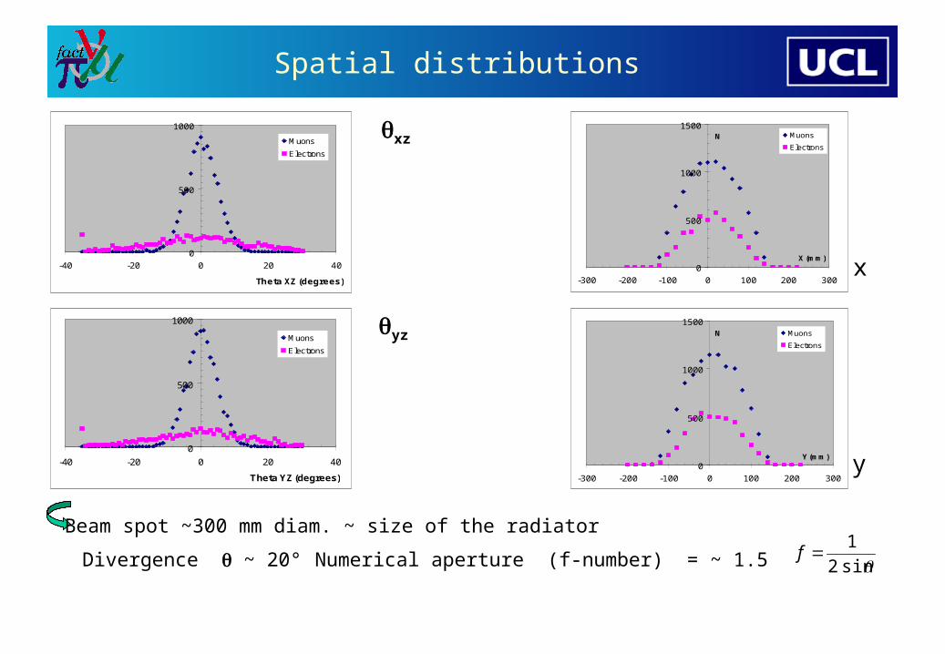
Spatial distributions
0
500
1000
1500
-300 -200 -100 0 100 200 300
X (mm)
N Muons
Electrons
0
500
1000
1500
-300 -200 -100 0 100 200 300
Y (mm)
N Muons
Electrons
Beam spot ~300 mm diam. ~ size of the radiator
Numerical aperture (f-number) = ~ 1.5
x
y
0
500
1000
-40 -20 0 20 40
Theta XZ (degrees)
Muons
Electrons
0
500
1000
-40 -20 0 20 40
Theta YZ (degrees)
Muons
Electrons
xz
yz
Divergence ~ 20° sin2
1f

Angular and energy distributions
0
200
400
600
800
1000
1200
1400
0 10 20 30 40
Theta (degrees)
N
Muons
Electrons
0
200
400
600
800
1000
1200
1400
1600
1800
0 100 200 300 400 500Total energy (MeV)
N
Muons
Electrons
Angle with respect to beam axis
Kinetic energy distribution
It is not obvious (to me) to separate e- on calorimetric principles at such low electron energies!
Electrons have very low energies ( E< m )

Č radiator n= 1.25
n= 1.25
0
1000
2000
3000
0 20 40 60 80
Cerenkov angle (degrees)
NElectrons
Muons
0
500
1000
1500
2000
2500
0 100 200 300 400 500 600 700
Photoelectrons
N Electrons
Muons
Distribution of light yield
Distribution of Čerenkov angle
( 10 cm thick radiator )
200-400 photoelectrons
Overlap between the angle distributions

Questions
Consequences of
- large beam spot- large beam divergence- energy distributions- Overlap of Čerenkov angle distributions
How to identify e- on the basis of the Čerenkov angle ?
Ref. L. Cremaldi, D. Summers
(at the exit of the solenoid)
Try other radiators with smaller indices !
With a radiator n=1.25

Contamination
0.00
0.02
0.04
0.06
0.08
0.10
0.12
0.14
0.16
0.18
0.20
1 1.02 1.04 1.06 1.08 1.1 1.12
Index of refraction
% M
uo
n c
on
tam
inati
on
Gases Liquids
Definition. Contamination = relative nr. of electrons counted as muonsRef. http://www.fynu.ucl.ac.be/themes/he/mice (May 02, 2002)
Assumptions
- detection thresh. = 10 .e
- «» no signal
More and more low energy electrons do not give a signal
Less and less muons do not give Č light
thresholdbelow
thresholdbelow
e
e
)(
)(

Tools and strategy
Particle files
Photon files
Optics
Mech. design
Mathematica v.3
Zemax v.2002
Autocad 2002
Objects ToolsStatus
Operational
Operational
Stray magnetic fieldnot yet done !
Operational
General features
1. Do not put photomultipliers in the particle beam
generation of spurious photons in glas window of photodetector !
« folded » optical system
2. Influence of stray magnetic field
shielding needed ?
3. Detection of a small number of photons with ~ 400 nm
photomultipliers with high gains and negligible noise
+ matching emission spectrum with photodetector response

Magnetic stray field
*
Photodetector at 1 m on the beam axis
Photodetector at 1 m away from the beam axis
and 1 m downstream from end of solenoid
Ref. R.B. Palmer, R. Fernow
Collaboration meeting27.10.2001
*
Confirmed by our own calculations with TOSCA

Case study
End of solenoid(4 Tesla – inner diam. 500 mm)
Magn. shielding(central opening diam. 400)
Aerogel radiator n=1.06300 mm x 300 mm 10 mminside a tube with reflective inner walls
Spheroidal mirror
Photodetector(s)
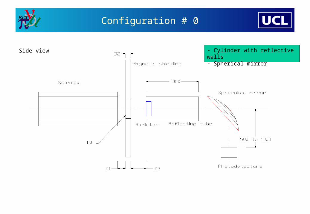
Configuration # 0
Side view - Cylinder with reflective walls- Spherical mirror

Tracking of photons
… for a single photon
… for a single electron
… for 3 electrons
Simplest case Hypothetical detection plane
… for the complete sample (4256 electrons)

Light collection efficiency #0
Light intensity distribution in a hypothetical detection plane 150 mm from beam axis
1. Surface of blue square = 600 mm x 600 mm
Notes.
Light collection efficiency = 95 %
2. No optimization at all !
- detector plane not at a focal point …
- spherical mirror
3. Perfect reflectivity 100% on all surfaces
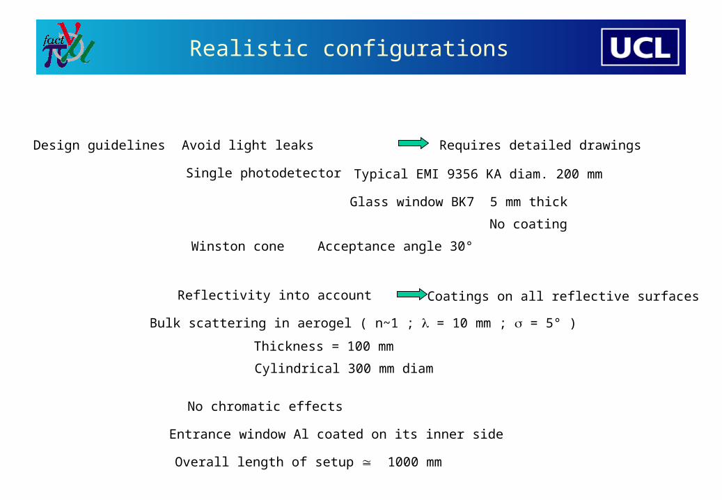
Realistic configurations
Design guidelines Avoid light leaks
Single photodetector
Reflectivity into account
Bulk scattering in aerogel ( n~1 ; = 10 mm ; = 5° )
Coatings on all reflective surfaces
Requires detailed drawings
Thickness = 100 mm
Overall length of setup 1000 mm
Typical EMI 9356 KA diam. 200 mm
Glass window BK7 5 mm thick
No coating
Cylindrical 300 mm diam
Entrance window Al coated on its inner side
Winston cone Acceptance angle 30°
No chromatic effects
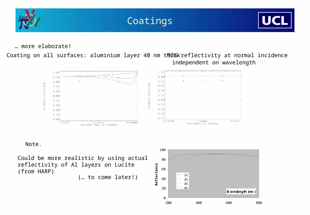
Coatings
… more elaborate!
Coating on all surfaces: aluminium layer 40 nm thick 92% reflectivity at normal incidenceindependent on wavelength
Could be more realistic by using actualreflectivity of Al layers on Lucite(from HARP)
0
20
40
60
80
100
200 400 600 800
Wavelength (nm)
Re
fle
cta
nc
e (
%)
1G
2G
3G
4G
(… to come later!)
Note.
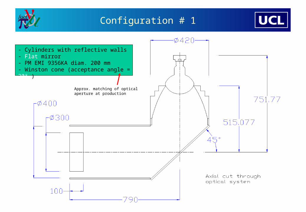
Configuration # 1
- Cylinders with reflective walls- Flat mirror- PM EMI 9356KA diam. 200 mm- Winston cone (acceptance angle = 30° )
Approx. matching of optical aperture at production
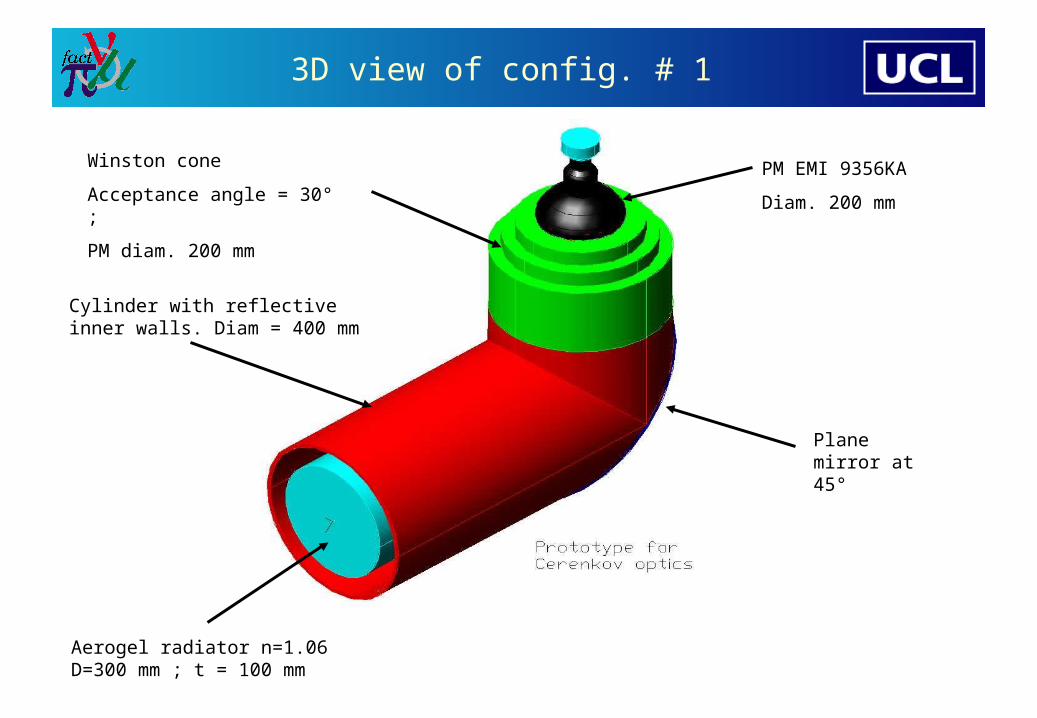
3D view of config. # 1
Aerogel radiator n=1.06D=300 mm ; t = 100 mm
Cylinder with reflectiveinner walls. Diam = 400 mm
Plane mirror at 45°
Winston cone
Acceptance angle = 30° ;
PM diam. 200 mm
PM EMI 9356KA
Diam. 200 mm
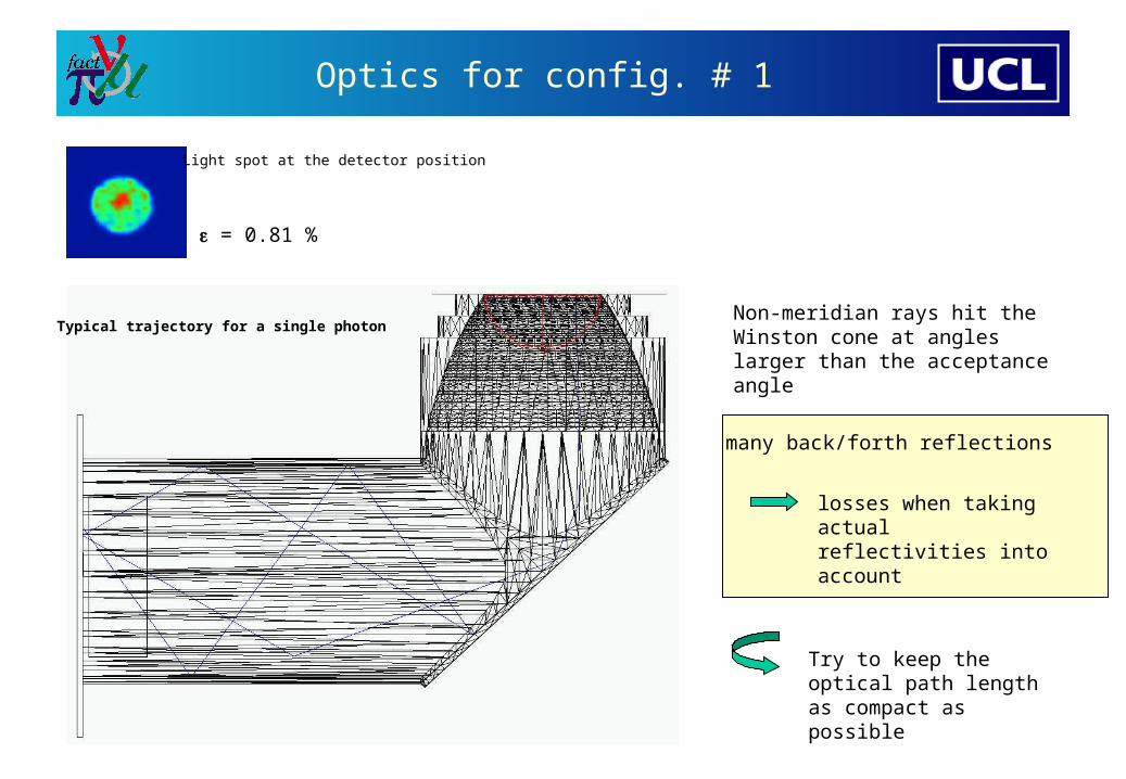
Optics for config. # 1
= 0.81 %
losses when taking actual reflectivities into account
Typical trajectory for a single photon
Light spot at the detector position
Non-meridian rays hit the Winston cone at angles larger than the acceptance angle
many back/forth reflections
Try to keep the optical path length as compact as possible
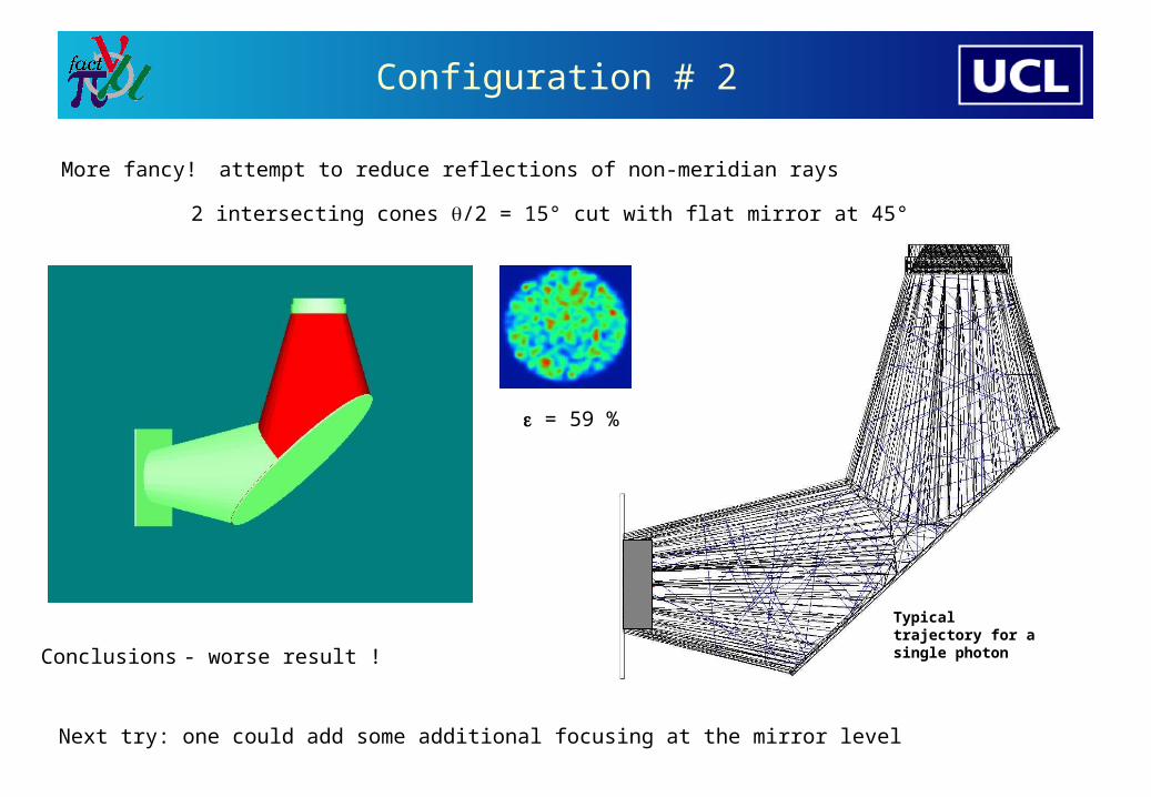
Configuration # 2
More fancy!
2 intersecting cones /2 = 15° cut with flat mirror at 45°
attempt to reduce reflections of non-meridian rays
= 59 %
Conclusions
Next try: one could add some additional focusing at the mirror level
- worse result !
Typical trajectory for a single photon

Configuration #3
Spherical mirror R= 1500 mm
= 70 %
Typical trajectories for 5 photons
Most compact.
Note. Mirror radius not optimized!
Conclusion.
- Extended off-axis source object- short distances w.r.t. mirror radius- larger light spot (aberrations) compared to config. #1- (probably) no change with elliptical mirror (except cost).

Summary
3 configurations studied with a single PM detector + Winston cone assembly
Realistic coatings, bulk scattering included
1. Plane mirror + reflecting cylinders
= 0.81 %
2. Plane mirror + reflecting cones
= 59 %
3. Spherical mirror + reflecting cylinders
= 70 %
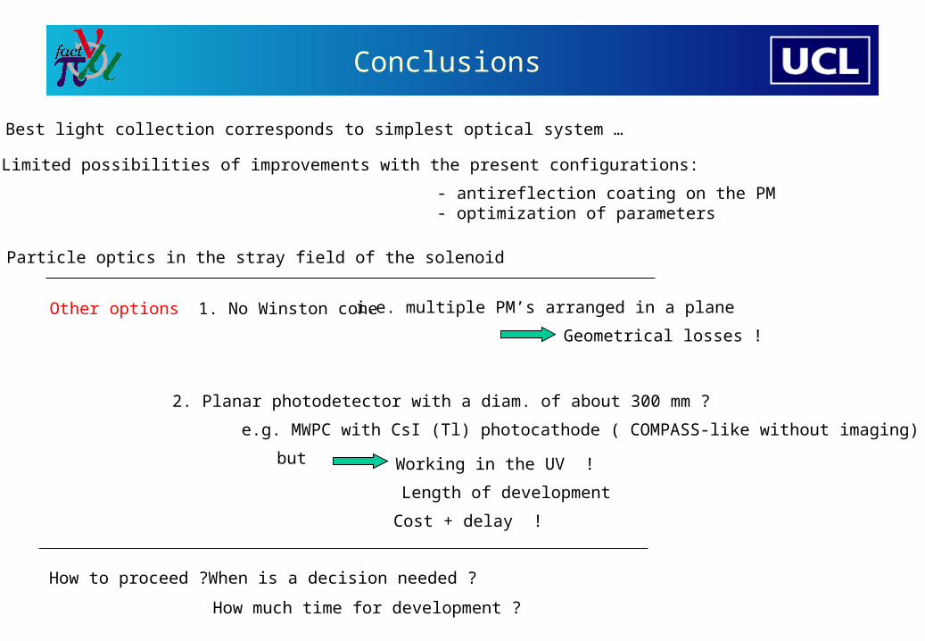
Conclusions
Best light collection corresponds to simplest optical system …
Limited possibilities of improvements with the present configurations:
- antireflection coating on the PM- optimization of parameters
Other options 1. No Winston cone i.e. multiple PM’s arranged in a plane
Geometrical losses !
2. Planar photodetector with a diam. of about 300 mm ?
e.g. MWPC with CsI (Tl) photocathode ( COMPASS-like without imaging)
How to proceed ?
but Working in the UV !
Length of development
Cost + delay !
When is a decision needed ?
How much time for development ?
Particle optics in the stray field of the solenoid
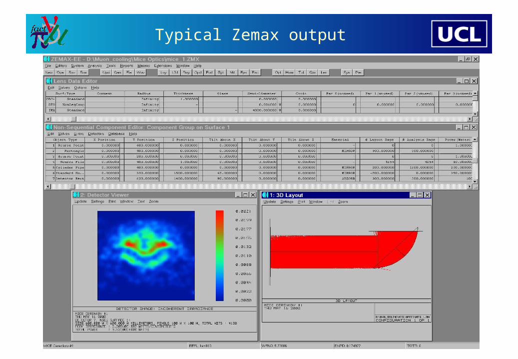
Typical Zemax output
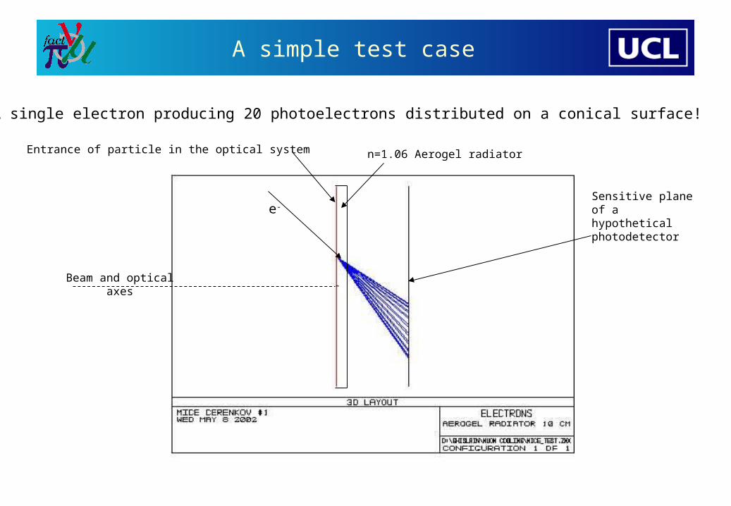
A simple test case
Entrance of particle in the optical system
Sensitive plane of a hypothetical photodetector
A single electron producing 20 photoelectrons distributed on a conical surface!
Beam and opticalaxes
n=1.06 Aerogel radiator
e-

… and the intensity distribution
Intensity distribution on a detection plane perpendicular to optical axis (for the simplest case shown before)