sistem pengesanan kenderaan kecemasan melalui nilai frekuensi ...
Upload
nguyendieuCategory
view
213download
0
e-FireXIT: A SMART ROUTE DECISION MAKING SYSTEM TO
EMERGENCY EXIT
LOO LOK SIANG
This Report Is Submitted In Partial Fulfillment Of Requirements For The
Bachelor Degree of Electronic Engineering (Computer Engineering) With
Honours
Fakulti Kejuruteraan Elektronik dan Kejuruteraan Komputer
Universiti Teknikal Malaysia Melaka
June 2013

Tajuk Projek
SesiPengajian
UNTYERSTI TEKNIKAL MALAYSIA MELAKAFAKULTI KEJURUTERAAN ELEKTRONIK DAN KEJURUTERAAN KOMPUTER
BORANG PENGESAHAN STATUS LAPORAN
PROJEK SARJANA MUDA II
e-FireXIT: A Smart Route Decision Making System toExit
1 2 I aJ
Saya LOO LOK SIANG
(HURUFBESAR)mengaku membenarkan Laporan Projek Sarjana Muda ini disimpan di Perpustakaan dengan syarat-syarat kegunaan seperti berikut:
l. Laporan adalah hakmilik Universiti Teknikal Malaysia Melaka.
2- Perpustakaan dibenarkan membuat salinan untuk tujuan pengajian satraja.
3. Perpustakaan dibenarkan membuat salinan laporan ini sebagai bahan pertukaran antara institusi
pengajian tinggi.
4. Silatandakan( { ):
EEZ
ST]LIT*
TERHAD**
TIDAKTERIIAD
*(Mengandungi maklumat yang berdarjah keselamatan ataukepentingan Malaysia seperti yang termaktub di dalam AKTARArrsrA RASMr 1972)
**(Mengandungi maklumat terhad yang telah ditentukan olehorganisasi/badan di mana penyelidikan dijalankan)
(COP DAN TANDATANGAN PENYELIA)
Ef{GR. VIGIIESWARA RAO A'L GAIilAPATI{YPensy.tah
Frkslti l(rlurulorl.tr Elalronik D.n xcrtlru.raan KornputorUnivorrit T.lmik.l M.Lysie Mehka (UT6M)
Ha.10 Tu.h Jeyr,1100 Ourm Tur€e6l iicleka
,.*,\ola_fx)5

111
"A1l the trademark and copyright use herein are property of their respective owner.
References of inforrnation from other sources are quoted accordingly; otherwise the
information presented in this report is solely work of the author."
Author : Loo Lok Siang
Date : 12 June 2013

1V
"I hereby acknowledge that the scope and qualrty of this thesis is qualified for the
award of the Bachelor Degree of Electronic Engineering (Computer Engineering)
With Honours."
Signature : ... ... ... ....\.
Author : Engr. Vigneswara Rao Gannapathy
Date , ):f t1+:'r

v
Specially dedicated to
My beloved parents
Loo Peng Khoon & Lee Ah Hiong
My supervisor
Engr. Vigneswara Rao Gannapathy
and those people who have guide me throughout my journey of education

vi
ACKNOWLEDGEMENT
First and foremost I offer my sincerest gratitude to my supervisor, Engr
Vigneswara Rao Gannapathy, who has supported me throughout my thesis with his
patience and knowledge. I attribute the level of my bachelor degree to his
encouragement and effort and without him this thesis, would not have been
completed or written.
I am indebted with my friends and laboratory technicians as they directly or
indirectly offer me support and guidance to complete the project.
Finally, I thank my parents for supporting me throughout all my studies at
university.
vii
ABSTRAK
Adalah dilaporkan bahawa apabila berlaku kebakaran, kebanyakan penghuni
bangunan akan mengambil masa yang agak lama untuk menyelamatkan diri ke luar
bangunan. Ini kerana orang ramai perlu mencari lokasi pintu keluar kecemasan.
Lampu keluar kecemasan juga mungkin dihalang oleh asap hitam dan orang ramai
akan terlepas pandang jika terdapat jarak di antara orang dengan lampu keluar
kecemasan. Projek ini mencadangkan sistem e-FireXIT untuk menandatanagni
masalah ini dan mengetuai penghuni bangunan menyelamatkan diri menggunakan
laluan yang paling selamat dan terdekat ke pintu keluar kecemasan. Sistem tersebut
juga boleh mengubah laluan secara automatik ke laluan yang selamat jika api berlaku
menyebabkan laluan itu tidak selamat digunakan. Dengan menyatukan sistem
pengumuman awam ke dalama sistem e-FireXIT, ia akan memberi pengumuman
tentang laluan terselamat untuk digunakan. Kesannya, proses pemindahan akan
menjadi lebih cepat.
viii
ABSTRACT
It was reported that during fire break out, the building occupant spend more
time to evacuate from the building. This is due to the people need to find where is the
location of emergency exit doors. The exit signs are also covered by black smoke and
they missed it if there is a distance between the people and the signs. This project
proposed the e-FireXIT system to overcome the problems and guide the building
occupant to emergency exit doors via the safest and nearest exit points. The system
will reroute itself to another exit points if any of it is engulfed in fire that result not
safe to exit. The public announcement system also integrated with e-FireXIT system
to make an announcement on the safest exit points. Thus, through this system, the
evacuation become more faster.

ix
TABLE OF CONTENT
CHAPTER CONTENT PAGE
PROJECT TITLE i
STATUS REPORT CONFIRMATION ii
DECLARATION iii
DEDICATION v
ACKNOWLEDGEMENT vi
ABSTRAK vii
ABSTRACT viii
TABLE OF CONTENT ix
LIST OF TABLES xii
LIST OF FIGURES xiii
LIST OF ABBREVIATIONS xvi
LIST OF APPENDICES xvii
I INTRODUCTION 1
1.1 INTRODUCTION 1
1.2 OBJECTIVE 2
1.3 PROBLEM STATEMENT 2
1.3.1 Highlighted Accident 3
1.4 SCOPES OF PROJECT 4
1.4.1 User 4
1.4.2 Software Development 4
1.4.3 Hardware Development 4
x
1.5 BRIEF METHODOLOGY 5
1.6 THESIS OUTLINE 6
II LITERATURE REVIEW 8
2.1 INDOOR FLUORESCENT LIGHTS AND
EMERGENCY EXIT LIGHTS 8
2.2 EXIT PATH 9
2.3 EMERGENCY LIGHTING 9
2.4 EMERGENCY POWER SYSTEM 10
2.5 TEMPERATURE SENSOR 11
2.5.1 Thermocouple 11
2.5.2 Resistance Temperature Detector 12
2.5.3 Thermistor 13
2.5.4 Summary 14
2.6 SMOKE SENSOR 15
2.6.1 Photoelectric Smoke Alarm 15
2.6.2 Ionisation Smoke Alarm 16
2.7 OTHER APPROACH TO COUNTERMEASURE
FIRE BREAK OUT 17
2.7.1 Opportunistic Communications Based
Evacuation System 17
2.7.2 Portable Fire Evacuation Guide Robot System 19
2.7.3 Photoluminescent Marker 22
III METHODOLOGY 23
3.1 PROJECT METHODOLOGY 23
3.1.1 Software Design 23
3.1.2 Hardware Design 25
3.1.3 Software And Hardware Integration 26
3.1.4 Prototype Implementation 26
3.2 SURFACE MOUNT DEVICE 30

xi
3.2.1 Hand Soldering Surface Mount Device 30
3.2.2 Hand De-soldering Surface Mount Device 34
IV RESULT AND DISCUSSION 35
4.1 RESULT 35
4.1.1 LEDs Display Board 35
4.1.2 Main Controller 37
4.1.3 The e-FireXIT 38
4.1.4 Installation of e-FireXIT in Real Building 43
4.2 DISCUSSION 44
V CONCLUSION AND RECOMMENDATION 46
5.1 CONCLUSION 46
5.2 RECOMMENDATION 47
REFERENCES 48
APPENDICES 50

xii
LIST OF TABLES
NO TITLE PAGE
2.1 Advantages and disadvantages of temperature sensors 14
4.1 Truth table of the e-FireXIT 38

xiii
LIST OF FIGURES
NO TITLE PAGE
1.1 The fire incident in Philippine department store 3
1.2 Project workflow 5
2.1 Definition of 1 foot candle and 1 lumen per square foot 10
2.2 A backup power fuel cell 11
2.3 Thermocouple 11
2.4 Thermocouple Circuit 12
2.5 A schematic diagram of a typical RTD 13
2.6 Thermistors 14
2.7 A photoelectric smoke alarm 15
2.8 A photoelectric smoke alarm is triggered 16
2.9 An ionisation smoke alarm 17
2.10 An ionisation smoke alarm is triggered 17
2.11 The Opportunistic Communications based Evacuation System 18
2.12 Application scenario for the evacuation robot 19
2.13 Overall architecture of the evacuation robot 20
2.14 Activity flow chart expected scenario 20
2.15 Voice communication scenario for rescue 21
2.16 A photoluminescent marker building 22
3.1 Schematic Circuit designed from Proteus ISIS 7 Professional 24
3.2 Schematic Circuit designed from Proteus ISIS 7 Professional 24

xiv
3.3 PCB layout designed from Proteus ARES 7 Professional 25
3.4 PCB layout designed from Proteus ARES 7 Professional 25
3.5 Fabricated PCB LEDs display board 26
3.6 The e-FireXIT system 27
3.7 Possible output such as “Up”, “Down”, “Left”, “Right” and “Not
Safe to Enter” from LEDs display board
27
3.8 The e-FireXIT system is activated 28
3.9 The e-FireXIT system when one exit point is not safe to use 28
3.10 Flowchart of the e-FireXIT system 29
3.11 1210 package for bi-colour LED 30
3.12 1206 package for resistor 30
3.13 Soldering the SMD on a PCB 31
3.14 Hand Soldering SMD step 1 31
3.15 Hand Soldering SMD step 2 31
3.16 Hand Soldering SMD step 3 32
3.17 Hand Soldering SMD step 4 32
3.18 Hand Soldering SMD step 5 32
3.19 Hand Soldering SMD step 6 33
3.20 Hand Soldering SMD step 7 33
3.21 Hand Soldering SMD step 8 33
3.22 Hand Soldering SMD step 9 34
3.23 A rework station with hot air gun 34
4.1 LED display board 36
4.2 When green is turn on in the bi-colour LED 36
4.3 When red is turn on in the bi-colour LED 36
4.4 The controller box 38
4.5 The system in stand-by mode 39
4.6 The system is activated 40
4.7 Exit A is not safe to enter 40
4.8 Exit B is not safe to enter 41
4.9 Exit C is not safe to enter 41
4.10 Exit D is not safe to enter 42
4.11 Exit B & D are not safe to enter 42

xv
4.12 Exit A & C are not safe to enter 43
4.13 Exit B, C & D are not safe to enter 43
4.14 (a) The e-FireXIT is activated, (b) When a path to emergency exit
is not safe, it will switch from green arrow to red “X”
44
xvi
LIST OF ABBREVIATIONS
PIC – Peripheral Interface Controller
PCB – Printed Circuit Board
LED – Light Emitting Diode
SMD – Surface Mount Device
RTD – Resistance Temperature Detector
IDE – Integrated Development Environment
GPS – Global Positioning System
SMS – Short Message Service
UTeM – Universiti Teknikal Malaysia Melaka

xvii
LIST OF APPENDICES
NO TITLE PAGE
A Algorithm 50
B Project Source Code 52

CHAPTER I
INTRODUCTION
This chapter covered the Introduction of the project. It consists of objective,
problem statement, scopes of project and thesis outline. It also highlights the problem
of existing system and their limitations.
1.1 Introduction
The emergency exit lights are important signs during fire break out. When
fire break out, it serves as a guide for the building occupant to escape through safest
exit for immediate evacuation. However, current emergency exit signs are located
near to the emergency exit. It will be covered by black smoke and become invisible
to people eyes. Usually, they follow the majority people towards a same exit point
and this reduces the evacuation rate because only one emergency exit point is utilized
and focused on. A part from that, all paths used towards emergency exit doors will
2
gradually became not safe to use as the fire spread very fast. As a result, the public
could not identify which emergency exits are safe to move. Hence, this project
proposed an e-FireXIT: A Smart Route Decision Making System to Emergency Exit
that designed to guide the building occupant to the safest emergency exit for
effective and fast evacuation. It was also able to reroute the path to a safest
emergency exit points.
1.2 Objective
The objectives of this project are:
a. To develop indication paths for the building occupant to reach the safest exit
points for fast evacuation during fire break out.
b. To reroute the path to alternative exit points when any of the exits caught in
fire and unsafe to enter.
c. To incorporate the public announcement system to make a real time
announcement on safest exit point.
As a result, the people can escape faster by using the safest exit points.
1.3 Problem Statement
Many exit points’ exits in a building, result exit paths for each floor is
different due to its structure layout. When fire happens, the people in the building
find difficulty to find emergency exits. The fire can suddenly appear at any exit
points and block them to enter. This will cause the panic and probably trapped in
fired building.
Moreover, the smoke produced in the fire is usually thick, black and floated
upward to the ceiling. If fire break out and it produces a lot of smoke, the people
have to crawl on the floor to avoid it. The indoor illumination fluorescent lights are
located on top of the ceiling; meanwhile the emergency exit signs are install above
the emergency exit door. If the black smoke covers the upper lights from people’s
3
view, people may get confused between the emergency exit signs and the
illumination fluorescent lights. Thus, they could not find the direction to exit points.
Besides that, if the new building users are not familiar with the building
evacuation plan, they will find difficulty to escape when fire break out. As a result,
they will trap in the building. Furthermore, when fire break out, the new building
users are spending more time to search for an emergency exit. This will cause delay
and when time goes, the fire spreads very fast thus many exit points will become
unsafe.
1.3.1 Highlighted Accident
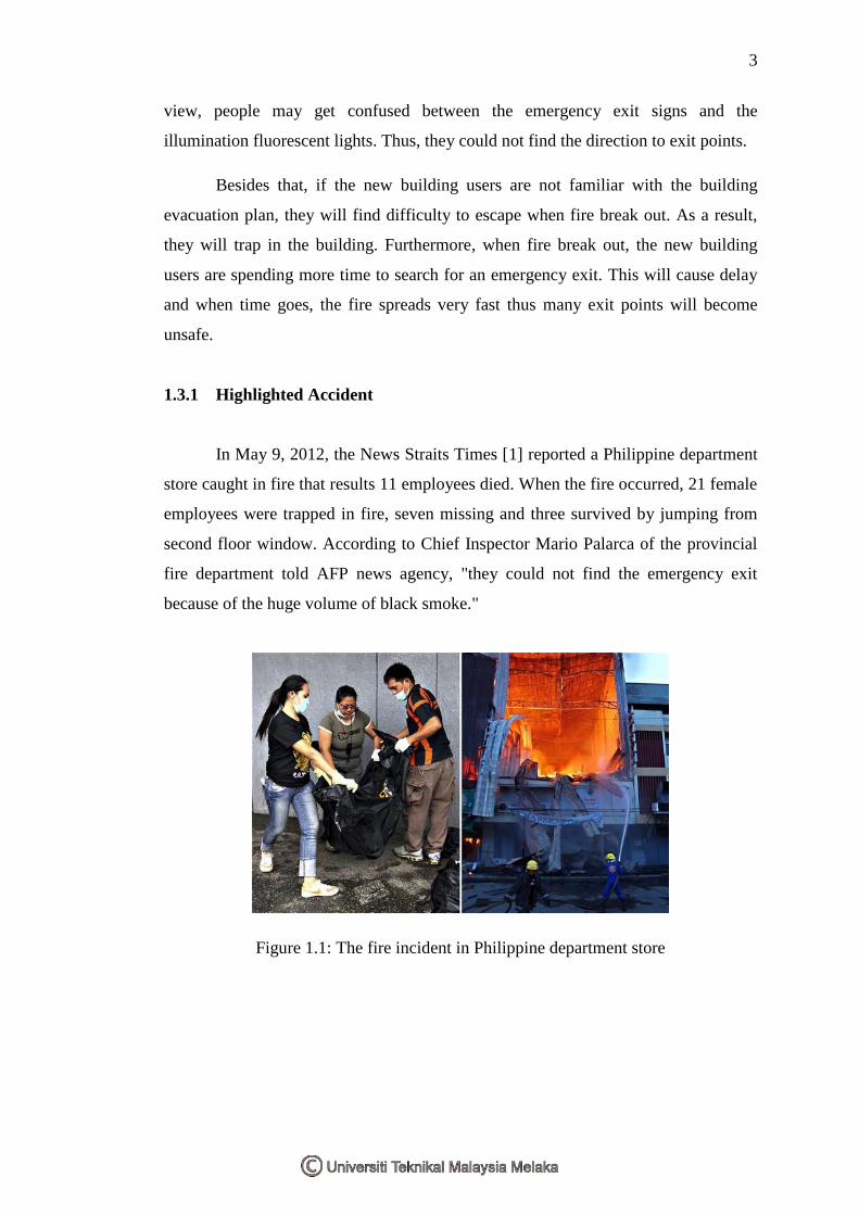
In May 9, 2012, the News Straits Times [1] reported a Philippine department
store caught in fire that results 11 employees died. When the fire occurred, 21 female
employees were trapped in fire, seven missing and three survived by jumping from
second floor window. According to Chief Inspector Mario Palarca of the provincial
fire department told AFP news agency, "they could not find the emergency exit
because of the huge volume of black smoke."
Figure 1.1: The fire incident in Philippine department store

4
1.4 Scopes of Project
1.4.1 User
The e-FireXIT system is designed to install in the building such as shopping
complexes, schools, hotels and offices. The building occupant will be benefited
during fire break out or any other emergency situations because the system can guide
them towards the safest exit points.
1.4.2 Software Development
The project starts with software development before move to hardware
development. In order to simulate and design the schematic circuit, software called
Proteus ISIS 7 Professional is used. The schematic circuit is simulated and re-
designed to achieve a desire output. Next, software called Proteus ARES 7
Professional is used to design Printed Circuit Board (PCB) layout based on the
schematic circuit. The PCB layout will be used in hardware development to fabricate
a real PCB. In addition, software called MPLAB IDE and C18 Compiler are used to
write a programming for the Peripheral Interface Controller (PIC) microcontroller.
The PIC model used is PIC18F4550.
1.4.3 Hardware Development
In hardware development, PCBs are fabricated in the fabrication laboratory.
The hardware is mainly developed by surface mount components such as bi-colour
LEDs and resistors. There is also a main controller box constructed with PIC, power
transistors, voltage regulators and switches. The smoke sensor and temperature
sensor (model LM35) are used to install on the exit points’ ceiling. Last but not least,
acrylic is used to construct the casing of the prototype to demonstrate the project
functionality in a miniature building.

5
1.5 Brief Methodology
The project workflow was showed in Figure 1.2.
Start
Project Proposal
Search for Information
Error?
Hardware Design
Software Testing
Software Design
Hardware Testing
Error?
Integrate Software & Hardware
Testing Prototype
Error?
Implement
Troubleshooting
Troubleshooting
Troubleshooting
Stop
Yes
Yes
Yes
No
No
No
Figure 1.2: Project workflow

6
All the information for this project are gathered from various resources such
as internet, journals, conferences and news articles. The gathered information is
useful to develop the e-FireXIT system.
The project starts with software design by designing a schematic circuit and
simulating it in Proteus ISIS 7 Professional environment. Next, the Proteus ARES 7
Professional is used to design the PCB layout based on the schematic circuit. Then,
MPLAB IDE and C18 Compiler are used to write a programming for the
microcontroller. The programming will test and debug to build a perfect and stable
coding.
In hardware design, the PCB is fabricated according to the design layout.
There are total nine PCB boards in use: one controller board and eight LEDs display
boards. Next, the surface mount components such as LEDs and resistors are soldered
on the fabricated PCB boards. Each PCB is tested individually to observe the output.
A troubleshooting is performed on the circuit if a desired output is not obtained.
The software and hardware are integrated and tested for its functionality. If
there are any errors occurred, a troubleshooting will be performed to ensure both
software and hardware work properly. This is the method used to achieve the desired
result. Then, a prototype is built to make it resembled a miniature building and
installed the e-FireXIT system on it.
1.6 Thesis Outline
The thesis consists of five chapters such as Introduction, Literature Review,
Methodology, Result and Discussion, and Conclusion and Recommendation. The
first chapter devotes the brief idea of e-FireXIT. Then, it moves on to objectives and
problem statements. Finally, brief methodology will highlight the method to build
this project. A detailed methodology will be presented in Chapter 3.
Chapter 2 concerns about the theoretical background of the project. The
research is based on journals, standards, books, conferences and internet. The
information obtained is valuable to develop the project. Understanding about
7
electronic components data sheets also important as it provides the information about
its characteristics and how to properly use it.
Chapter 3 discusses the detail procedures to build the prototype such as hand
soldering and de-soldering SMD components. In first part, it shows how the
schematic circuit is simulated and fabricated into a real PCB board. In second part, it
includes the design and development of the prototype starts from a basic sketch.
Chapter 4 observes the result of this project. First, it highlights the result of
LEDs display board and controller board individually. The second part explains the
result of combining LEDs display and controller boards into a full function system.
Chapter 5 explains the project conclusion and recommendation. A brief
conclusion is given to conclude the findings of e-FireXIT system.