E ects of leakage inductance on the input current of...
11
Transcript of E ects of leakage inductance on the input current of...

Scientia Iranica D (2017) 24(6), 3193{3203
Sharif University of TechnologyScientia Iranica
Transactions D: Computer Science & Engineering and Electrical Engineeringwww.scientiairanica.com
E�ects of leakage inductance on the input current ofdouble-star diode recti�er with active inter-phasereactor
J. Wang and S. Yang�
School of Electrical Engineering and Automation, Harbin Institute of Technology, Harbin, China.
Received 19 September 2015; received in revised form 5 May 2016; accepted 4 July 2016
KEYWORDSDouble-star dioderecti�er;Leakage inductance;Input current THD;Active inter-phasereactor;The input current lagangle.
Abstract. An Active Inter-Phase Reactor (AIPR) is often employed to inject trianglecurrent to improve the input current quality of double-star diode recti�er. Due to theexisting leakage inductance of transformer, the input current harmonics suppression abilityof the injected triangle current would be weakened. In this paper, the current commutationprocess of the double-star diode recti�er with AIPR is analyzed initially. Then, accordingto the relation between the input current and output current of the double-star transformer,the relation between the leakage inductance and the input line current of double-star dioderecti�er with AIPR is established. Such factors like the input current THD, the inputcurrent lag angle, and power factor of the double-star diode recti�er with AIPR as wellas their relations with the leakage inductance are also obtained. The theoretical analysisdemonstrates that leakage inductance increases the input current THD and lag angle. Itindicates that leakage inductance decreases the displacement factor and power factor. Toensure the input current THD is less than 5% and the power factor is more than 0.998,the leakage inductance factor, KLS , should be less than 0.22. Simulation results verify thetheoretical analysis.© 2017 Sharif University of Technology. All rights reserved.
1. Introduction
Diode recti�ers are widely used due to their ruggedness,simplicity, and low price [1,2]. However, they drawdistorted currents from the ac supply and do notmeet the requirements of the harmonics standard [3,4].Therefore, researchers have explored a variety of meth-ods to reduce the input line current distortion of dioderecti�ers in recent decades [5-26]. Compared with otherharmonic reduction methods, because of the small kilo-
*. Corresponding author. Tel.: +86 045186413301;Fax: +86 13804506002E-mail addresses: [email protected] (J. Wang);[email protected] (S. Yang)
doi: 10.24200/sci.2017.4353
Volt Ampere (kVA) rating of auxiliary current injectioncircuit and excellent harmonic reduction ability, themethod of active harmonic reduction at dc side issuitable for high power applications and has drawnmore and more attention [16-26].
In [18], the concept of Active Inter-Phase Reactor(AIPR) was proposed in 12-pulse diode recti�er. Thelow-kVA (2% Po) active auxiliary circuit injects atriangular current into the extra winding of the AIPR.The resulting system draws near sinusoidal input cur-rents with less than 1% THD. In [19], the method toreduce the ac-side harmonics of series-connected 12-pulse diode recti�er utilizing dc-side active auxiliarycircuit formed by two buck-and-boost converters ispresented. The auxiliary circuit is placed parallel toeach six-pulse recti�er bridge to inject current andshape the recti�er output current. The resulting THD
3194 J. Wang and S. Yang/Scientia Iranica, Transactions D: Computer Science & ... 24 (2017) 3193{3203
is below 5% and the kilovolt ampere rating of auxiliarycircuit is less than 15% Po. In [20], an AIPR scheme toachieve near sinusoidal input line currents for a 24-pulseconverter is proposed. The proposed AIPT schemeconsists of three IPTs and a current-controlled inverterwith rating required to be only 1.16% of the systempower rating. In [21], a double-star diode recti�erwith an auxiliary PWM recti�er is also presented. Itdraws near sinusoidal utility line currents with lessthan 5% THD. Besides the introduced dc-side activecurrent injection schemes, the authors in [22-26] alsoproposed diode recti�ers with an auxiliary currentinjection circuit at dc-side.
However, those dc-side active current injectionschemes were not concerned with the e�ects of leakageinductance of transformer. In the high power applica-tions, the e�ects of the leakage inductance of trans-former are more serious and should not be ignored.In order to clarify the e�ects of leakage inductance of
transformer on the input current, this paper sets thedouble-star diode recti�er with AIPR as an exampleand the e�ects of leakage inductance of transformer onthe input current are analyzed in depth. Due to theessence of the diode recti�ers, the same active currentinjection reduction method is used; the analysis ofthe e�ects of leakage inductance of transformer on theinput current can be extended to other diode recti�erswith active current injection circuit.
2. Theoretical analysis
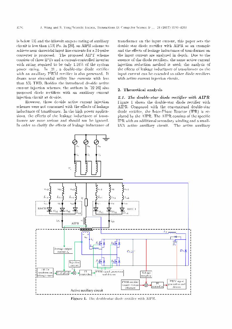
2.1. The double-star diode recti�er with AIPRFigure 1 shows the double-star diode recti�er withAIPR. Compared with the conventional double-stardiode recti�er, the Inter-Phase Reactor (IPR) is re-placed by the AIPR. The AIPR consists of the speci�cIPR with an additional secondary winding and a small-kVA active auxiliary circuit. The active auxiliary
Figure 1. The double-star diode recti�er with AIPR.
J. Wang and S. Yang/Scientia Iranica, Transactions D: Computer Science & ... 24 (2017) 3193{3203 3195
circuit consists of the auxiliary PWM recti�er and thebuck conventer. The auxiliary PWM recti�er injectsthe triangle current into the double-star diode recti�erto shape the distorted input line current as sine waveapproximately. The buck converter is used to feed theharmonic power absorbed by single PWM recti�er tothe load. In Figure 1, the output voltage referenceof auxiliary PWM recti�er is designed according tothe input voltage of auxiliary PWM recti�er and theload current. The output voltage control loop of theauxiliary PWM recti�er is employed to maintain theoutput voltage as the output voltage reference, whichhelps the auxiliary PWM recti�er to inject the requiredtriangle current accurately. When the harmonic powerabsorbed by single PWM recti�er changes, the outputvoltage of auxiliary PWM recti�er changes; then, theoutput signals of voltage simple and PI regulatorschange; the duty cycle of buck converter is adjustedcorrespondingly. It indicates that the harmonic powerfed to the load is changed. Finally, output voltage ofthe auxiliary PWM recti�er is adjusted and maintainedas the output voltage reference.
The injected triangle current, is, meets:
is =
8>>>>>>>>>>>>>>><>>>>>>>>>>>>>>>:
3Idm� � !t� Id
2m 0 � !t � �3
� 3Idm� � !t+ 3Id
2m�3 � !t � 2�
3
3Idm� � !t� 5Id
2m2�3 � !t � �
� 3Idm� � !t+ 7Id
2m � � !t � 4�3
3Idm� � !t� 9Id
2m4�3 � !t � 5�
3
� 3Idm� � !t+ 11Id
2m5�3 � 2!t � 2�
(1)
where Id is the average output current of the double-star diode recti�er, and m is the turn ratio between thesecondary and primary windings of the speci�c IPR.
In Figure 1, La1, Lb1, Lc1, La2, Lb2, and Lc2are the equivalent leakage inductances of double-startransformer. The values of leakage inductance areassumed to be the same. That is:
La1 = Lb1 = Lc1 = La2 = Lb2 = Lc2 = LS : (2)
The double-star diode recti�er is supplied by a bal-anced three-phase voltage system:8>>>><>>>>:
ua = Um sin(!t)
ub = Um sin(!t� 2�=3)
uc = Um sin(!t+ 2�=3)
(3)
where Um is the amplitude of input phase voltage.Assuming that the turn ratio of double-star trans-
former is 1:k, the output voltages of secondary-windingdouble-star transformer are:8>>>><>>>>:
ua1 =p
3Umk sin(!t+ �=6)
ub1 =p
3Umk sin(!t� �=2)
uc1 =p
3Umk sin(!t+ 5�=6)
(4)
8>>>><>>>>:ua2 =
p3Umk sin(!t� 5�=6)
ub2 =p
3Umk sin(!t+ �=2)
uc2 =p
3Umk sin(!t� �=6)
(5)
According to the Kirchho�'s current law and theAmpere-turns balance law of the transformer, the inputcurrent of the double-star recti�er is:8>>>><>>>>:
ia = 1k (ia1 � ia2 + ic2 � ic1)
ib = 1k (ib1 � ib2 + ia2 � ia1)
ic = 1k (ic1 � ic2 + ib2 � ib1)
(6)
2.2. Current commutation process of thedouble-star diode recti�er with AIPR
When the triangle current, is, is injected into the ad-ditional secondary winding of the speci�c IPR, outputcurrents of two three-phase half-wave recti�ers are:
id1 =
8>>>>><>>>>>:Id2
� 6� ��!t� 2�
3 p��
2�3 p � !t � 2�
3
�p+ 1
2
�Id2
�� 6� ��!t� 2�
3 p�
+ 4�
2�3
�p+ 1
2
� � !t � 2�3 (p+ 1)
(7)
id2 =
8>>>>><>>>>>:Id � Id
2
� 6� ��!t� 2�
3 p��
2�3 p � !t � 2�
3
�p+ 1
2
�Id2
� 6� ��!t� 2�
3 p�� 2
�2�3
�p+ 1
2
� � !t � 2�3 (p+ 1)
(8)
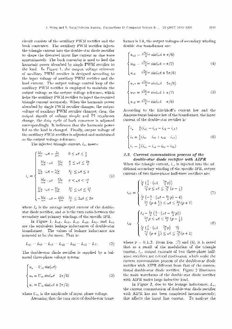
where p = 0; 1; 2. From Eqs. (7) and (8), it is notedthat as a result of the modulation of the trianglecurrent, is, output currents of two three-phase half-wave recti�ers are critical continuous, which make thecurrent commutation process of the double-star dioderecti�er with AIPR di�erent from that of the conven-tional double-star diode recti�er. Figure 2 illustratesthe main waveforms of the double-star diode recti�erwith AIPR under large inductive load.
In Figure 2, due to the leakage inductance, Ls,the current commutation of double-star diode recti�erwith AIPR has not been completed instantaneously;this a�ects the input line current. To analyze the
3196 J. Wang and S. Yang/Scientia Iranica, Transactions D: Computer Science & ... 24 (2017) 3193{3203
Figure 2. Main waveforms of the double-star dioderecti�er with AIPR: (a) The injected triangle current, (b)output currents of two three-phase half-wave recti�ers, (c)input voltages of three-phase half-wave recti�ers, (d) inputcurrents of three-phase half-wave recti�ers, and (e) inputline currents of double-star diode recti�er with AIPR.
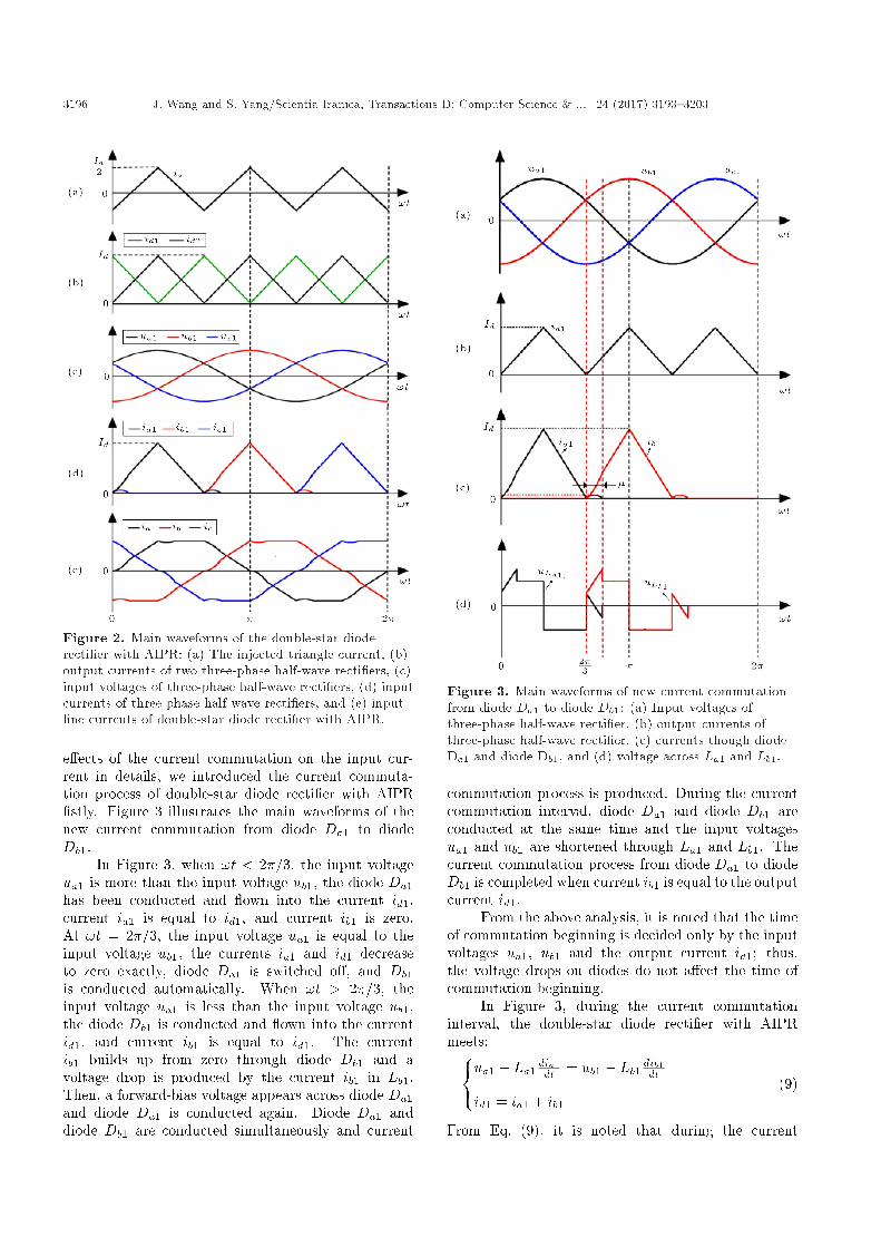
e�ects of the current commutation on the input cur-rent in details, we introduced the current commuta-tion process of double-star diode recti�er with AIPR�stly. Figure 3 illustrates the main waveforms of thenew current commutation from diode Da1 to diodeDb1.
In Figure 3, when !t < 2�=3, the input voltageua1 is more than the input voltage ub1, the diode Da1has been conducted and own into the current id1,current ia1 is equal to id1, and current ib1 is zero.At !t = 2�=3, the input voltage ua1 is equal to theinput voltage ub1, the currents ia1 and id1 decreaseto zero exactly, diode Da1 is switched o�, and Db1is conducted automatically. When !t > 2�=3, theinput voltage ua1 is less than the input voltage ub1,the diode Db1 is conducted and own into the currentid1, and current ib1 is equal to id1. The currentib1 builds up from zero through diode Db1 and avoltage drop is produced by the current ib1 in Lb1.Then, a forward-bias voltage appears across diode Da1and diode Da1 is conducted again. Diode Da1 anddiode Db1 are conducted simultaneously and current
Figure 3. Main waveforms of new current commutationfrom diode Da1 to diode Db1: (a) Input voltages ofthree-phase half-wave recti�er, (b) output currents ofthree-phase half-wave recti�er, (c) currents though diodeDa1 and diode Db1, and (d) voltage across La1 and Lb1.
commutation process is produced. During the currentcommutation interval, diode Da1 and diode Db1 areconducted at the same time and the input voltagesua1 and ub1 are shortened through La1 and Lb1. Thecurrent commutation process from diode Da1 to diodeDb1 is completed when current ib1 is equal to the outputcurrent id1.
From the above analysis, it is noted that the timeof commutation beginning is decided only by the inputvoltages ua1, ub1 and the output current id1; thus,the voltage drops on diodes do not a�ect the time ofcommutation beginning.
In Figure 3, during the current commutationinterval, the double-star diode recti�er with AIPRmeets:8<:ua1 � La1
dia1dt = ub1 � Lb1 dib1dt
id1 = ia1 + ib1(9)
From Eq. (9), it is noted that during the current
J. Wang and S. Yang/Scientia Iranica, Transactions D: Computer Science & ... 24 (2017) 3193{3203 3197
commutation interval, the voltage drops on diodes donot a�ect the current wave.
Solving Eq. (9), the currents ia1 and ib1 areobtained as:8>><>>:
ia1 = 3Id2�
�!t� 2�
3
�� p6U22Xs
�1�cos
�!t� 2�
3
��ib1 = 3Id
2�
�!t� 2�
3
�+p
6U22Xs
�1�cos
�!t� 2�
3
�� (10)
where U2 is the RMS value of input phase voltage ofthree-phase half-wave recti�er and Xs = !Ls is theleakage inductive reactance of transformer.
Considering that current ib1 changes from 0 toid1 in the current commutation interval, the relationbetween the overlap angle � and the circuit parameterscan be obtained:
3�XBId =p
6U2�(1� cos�): (11)
In Eq. (11), the overlap angle � is proportional tothe leakage inductance of transformer and dc outputcurrent, but it is inversely proportional to the outputvoltage of the double transformer.
2.3. E�ects of the leakage inductance on theinput current
According to Eq. (6) and Figure 1, in order to es-tablish the expression between the leakage inductiveof transformer and input current, the expression ofoutput currents of double-star transformer should becalculated �rstly.
From Eqs. (7) and (10), by combining the phaserelation between the currents ia1 and ib1, the outputcurrent ia1 of double-star transformer can be obtainedas:
ia1 =
8>>>>>>>>>>>>>>>>>>>><>>>>>>>>>>>>>>>>>>>>:
3Id2� !t+
p6U2
2Xs (1� cos(!t))0 � !t � �
3Id� !t � � !t � �
3
� 3Id� !t+ 2Id �
3 � !t � 2�3
3Id2�
�!t� 2�
3
�� p6U22Xs
�1� cos
�!t� 2�
3
��2�3 � !t � 2�
3 + �
0 2�3 + � � !t � 2�
(12)
Since the principle of six times current commutation isidentical in one-line period, according to the phase rela-tion among output currents of double-star transformer,which is shown in Figure 4, the output currents ofdouble-star transformer ia2, ic1, and ic2 are calculatedas:
Figure 4. The phase relation among output currents ofdouble-star transformer.
ia2 =
8>>>>>>>>>>>>>>>>>>>><>>>>>>>>>>>>>>>>>>>>:
0 0 � !t � �3Id2� (!t� �) +
p6U2
2Xs (1� cos(!t� �))� � !t � � + �
3Id� (!t� �) � + � � !t � 4�
3
� 3Id� (!t� �) + 2Id 4�
3 � !t � 5�3
3Id2�
�!t� 5�
3
�� p6U22Xs
�1� cos
�!t� 5�
3
��5�3 � !t � 5�
3 + �
0 5�3 + � � !t � 2�
(13)
ic1 =
8>>>>>>>>>>>>>>>><>>>>>>>>>>>>>>>>:
3Id2� (!t)� p6U2
2Xs (1� cos(!t))0 � !t � �
0 � � !t � 4�3
3Id2�
�!t� 4�
3
�+p
6U22Xs
�1� cos
�!t� 4�
3
��4�3 � !t � 4�
3 + �
3Id�
�!t� 4�
3
� 4�3 + ��!t� 5�
3
�3Id�
�!t� 4�
3
�+2Id 5�
3 � !t � 2�
(14)
ic2 =
8>>>>>>>>>>>>>>>>>>>><>>>>>>>>>>>>>>>>>>>>:
0 0 � !t � �3
3Id2�
�!t� �
3
�+p
6U22Xs
�1� cos
�!t� �
3
���3 � !t � �
3 + �
3Id�
�!t� �
3
� �3 + � � !t � 2�
3
� 3Id�
�!t� �
3
�+ 2Id 2�
3 � !t � �3Id2� (!t� �)� p6U2
2Xs (1� cos(!t� �))� � !t � � + �
0 � + � � !t � 2�
(15)

3198 J. Wang and S. Yang/Scientia Iranica, Transactions D: Computer Science & ... 24 (2017) 3193{3203
Substituting Eqs. (12)-(15) into Eq. (6), the inputcurrent, ia, is:
ia =
8>>>>>>>>>>>>>>>>>>>>>>>>>>>>>>>>>>>>>>>>>>>>>>>>>>>><>>>>>>>>>>>>>>>>>>>>>>>>>>>>>>>>>>>>>>>>>>>>>>>>>>>>:
p6U2kXS (1� cos(!t)) 0 � !t � �3Id!tk� � � !t � �
3
Idk +
p6U2
2kXS
�1� cos
�!t� �
3
���3 � !t � �
3 + �
Idk
�3 + � � !t � 2�
3
2Idk � 3Id!t
2k� �p
6U22kXS
�1� cos
�!t� 2�
3
��2�3 � !t � 2�
3 + �
� 3Id(!t��3 )k� + 2Id
k2�3 + � � !t � �
�p6U2kXS (1� cos(!t� �))
� � !t � � + �
� 3Id(!t��)k� � + � � !t � 4�
3
� Idk �p
6U22kXS
�1� cos
�!t� 4�
3
��4�3 � !t � 4�
3 + �
� Idk 4�3 + � � !t � 5�
3
� 2Idk + 3Id(!t��)
2k� +p
6U22kXS
�1� cos
�!t� 5�
3
��5�3 � !t � 5�
3 + �
3Id(!t� 5�3 )
k� � 2Idk
5�3 + � � !t � 2�
(16)
The Root-Mean-Square (RMS) value and the funda-mental harmonic of the input current ia are calculatedas shown in Box I.
�1 is the input current lag angle, and it meetsRelation (20) as shown in Box II. To establish therelation between the input current and the leakageinductances of transformer in a general method, wede�ne the leakage inductance factor KLs as:
KLs =Xsp6U2
2Id
: (21)
Based on the relation between the overlap angle andthe circuit parameters shown in Eq. (11), the leakageinductance factor, KLs, is equal to 1 when the overlapangle is equal to the maximum value 60�.
According to the de�nition of the input currentTHD, combing Eqs. (19), (20), and (11), the inputcurrent THD of double-star diode recti�er with AIPRhas been calculated. Figure 5 illustrates the inputcurrent THDs of the conventional double-star dioderecti�er and the double-star diode recti�er with AIPRwhen the leakage inductance factor, KLs, changes from0 to 1.
In Figure 5, it is clear that the e�ects of leakageinductance on the input current THDs of conventionaldouble-star diode recti�er and double-star diode rec-ti�er with AIPR are di�erent. With the increase in
Figure 5. Relation between the input current THD andthe leakage inductance factor KLs.
IaRMS =p
162�3 cos�(2� cos�) + 243�2 sin�(cos�� 4) + 20�3(1� cos�)2 + 576�)6� 3
2 (1� cos�); (17)
Ia:1 =p
2Ia1RMS sin(!t+ �1); (18)
where:
Ia1RMS =3q
18(2 + � cos� sin�� �2 � 4 cos�+ 2 cos2 �)2 + 2(1� cos�)2(6 sin�� 3�� 3� cos�� 4p
3)2
4�2(1� cos�):(19)
Box I
J. Wang and S. Yang/Scientia Iranica, Transactions D: Computer Science & ... 24 (2017) 3193{3203 3199
�1 = arctan
6 cos� sin�� 3� cos2 �� 4
p3 cos�� 6 sin�+ 3�+ 4
p3
6 + 3� cos� sin�� 3�2 � 12 cos�+ 6 cos2 �
!: (20)
Box II
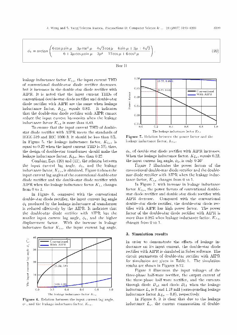
leakage inductance factor KLs, the input current THDof conventional double-star diode recti�er decreases,but it increases in the double-star diode recti�er withAIPR. It is noted that the input current THDs ofconventional double-star diode recti�er and double-stardiode recti�er with AIPR are the same when leakageinductance factor, KLs, equals 0.83. It indicatesthat the double-star diode recti�er with AIPR cannotreduce the input current harmonics when the leakageinductance factor KLs is more than 0.83.
To ensure that the input current THD of double-star diode recti�er with AIPR meets the standards ofIEEE-519 and IEC 1000-3, it should be less than 5%.In Figure 5, the leakage inductance factor, KLs, isequal to 0.22 when the input current THD is 5%; thus,the design of double-star transformer should make theleakage inductance factor, KLs, less than 0.22.
Combing Eqs. (20) and (11), the relation betweenthe input current lag angle, �1, and the leakageinductance factor, KLs, is obtained. Figure 6 shows theinput current lag angles of the conventional double-stardiode recti�er and the double-star diode recti�er withAIPR when the leakage inductance factor KLs changesfrom 0 to 1.
In Figure 6, compared with the conventionaldouble-star diode recti�er, the input current lag angle�1 produced by the leakage inductance of transformeris reduced e�ectively by the AIPR. It indicates thatthe double-star diode recti�er with AIPR has thesmaller input current lag angle, �1, and the higherdisplacement factor. With the increase in leakageinductance factor KLs, the input current lag angle,
Figure 6. Relation between the input current lag angle,�1, and the leakage inductance factor, KLs.
Figure 7. Relation between the power factor and theleakage inductance factor, KLs.
�1, of double-star diode recti�er with AIPR increases.When the leakage inductance factor, KLs, equals 0.22,the input current lag angle, �1, is only 0:36�.
Figure 7 illustrates the power factors of theconventional double-star diode recti�er and the double-star diode recti�er with AIPR when the leakage induc-tance factor, KLs, changes from 0 to 1.
In Figure 7, with increase in leakage inductancefactor KLs, the power factors of conventional double-star diode recti�er and double-star diode recti�er withAIPR decrease. Compared with the conventionaldouble-star diode recti�er, the double-star diode rec-ti�er with AIPR has high power factor. The powerfactor of the double-star diode recti�er with AIPR ismore than 0.985 when leakage inductance factor, KLs,changes from 0 to 1.
3. Simulation results
In order to demonstrate the e�ects of leakage in-ductance on its input current, the double-star dioderecti�er with AIPR is simulated in Saber software. Thecircuit parameters of double-star recti�er with AIPRfor simulation are given in Table 1. The simulationresults are shown in Figures 8-12.
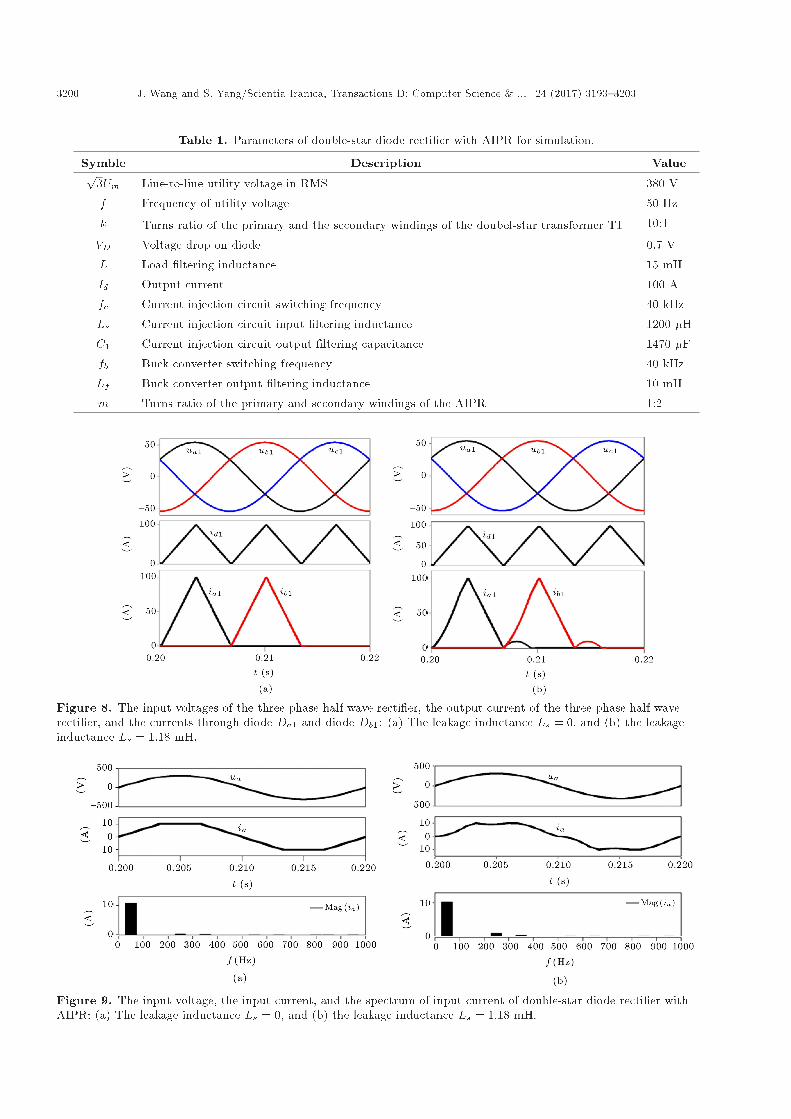
Figure 8 illustrates the input voltages of thethree-phase half-wave recti�er, the output current ofthe three-phase half-wave recti�er, and the currentsthrough diode Da1 and diode Db1 when the leakageinductance Ls is 0 and 1.18 mH (corresponding leakageinductance factor KLs = 0:8), respectively.
In Figure 8, it is clear that due to the leakageinductance Ls, the current commutation of double-
3200 J. Wang and S. Yang/Scientia Iranica, Transactions D: Computer Science & ... 24 (2017) 3193{3203
Table 1. Parameters of double-star diode recti�er with AIPR for simulation.
Symble Description Valuep3Um Line-to-line utility voltage in RMS 380 V
f Frequency of utility voltage 50 Hz
k Turns ratio of the primary and the secondary windings of the doubel-star transformer T1 10:1
VD Voltage drop on diode 0.7 V
L Load �ltering inductance 15 mH
Id Output current 100 A
fc Current injection circuit switching frequency 40 kHz
Ls Current injection circuit input �ltering inductance 1200 �H
C1 Current injection circuit output �ltering capacitance 1470 �F
fb Buck converter switching frequency 40 kHz
Lf Buck converter output �ltering inductance 10 mH
m Turns ratio of the primary and secondary windings of the AIPR 1:2
Figure 8. The input voltages of the three-phase half-wave recti�er, the output current of the three-phase half-waverecti�er, and the currents through diode Da1 and diode Db1: (a) The leakage inductance Ls = 0, and (b) the leakageinductance Ls = 1:18 mH.
Figure 9. The input voltage, the input current, and the spectrum of input current of double-star diode recti�er withAIPR: (a) The leakage inductance Ls = 0, and (b) the leakage inductance Ls = 1:18 mH.
J. Wang and S. Yang/Scientia Iranica, Transactions D: Computer Science & ... 24 (2017) 3193{3203 3201
Figure 10. The input current THD of double-star dioderecti�er with AIPR under di�erent leakage inductanceconditions.
Figure 11. The input current lag angle �1 of double-stardiode recti�er with AIPR under di�erent leakageinductance conditions.
Figure 12. The power factor of double-star diode recti�erwith AIPR under di�erent leakage inductance conditions.
star diode recti�er with AIPR cannot be completedinstantaneously; the current commutation from diodeDa1 to diode Db1 takes place under new currentcommutation mode.
Figure 9 illustrates the input voltage, the inputcurrent, and the spectrum of input current of double-star diode recti�er with AIPR when the leakage in-ductance Ls is 0 and 1.18 mH (corresponding leakageinductance factor KLs = 0:8), respectively.
Comparing Figure 9(a) and Figure 9(b), it is obvi-ous that the leakage inductance Ls leads to increase inthe input current harmonics. The input current THDincreases from 4.6% to 10.5%, which is consistent withthe theoretical analysis. Due to the leakage inductanceLs, the input current lag angle �1 also increases from0 to 2:5�.
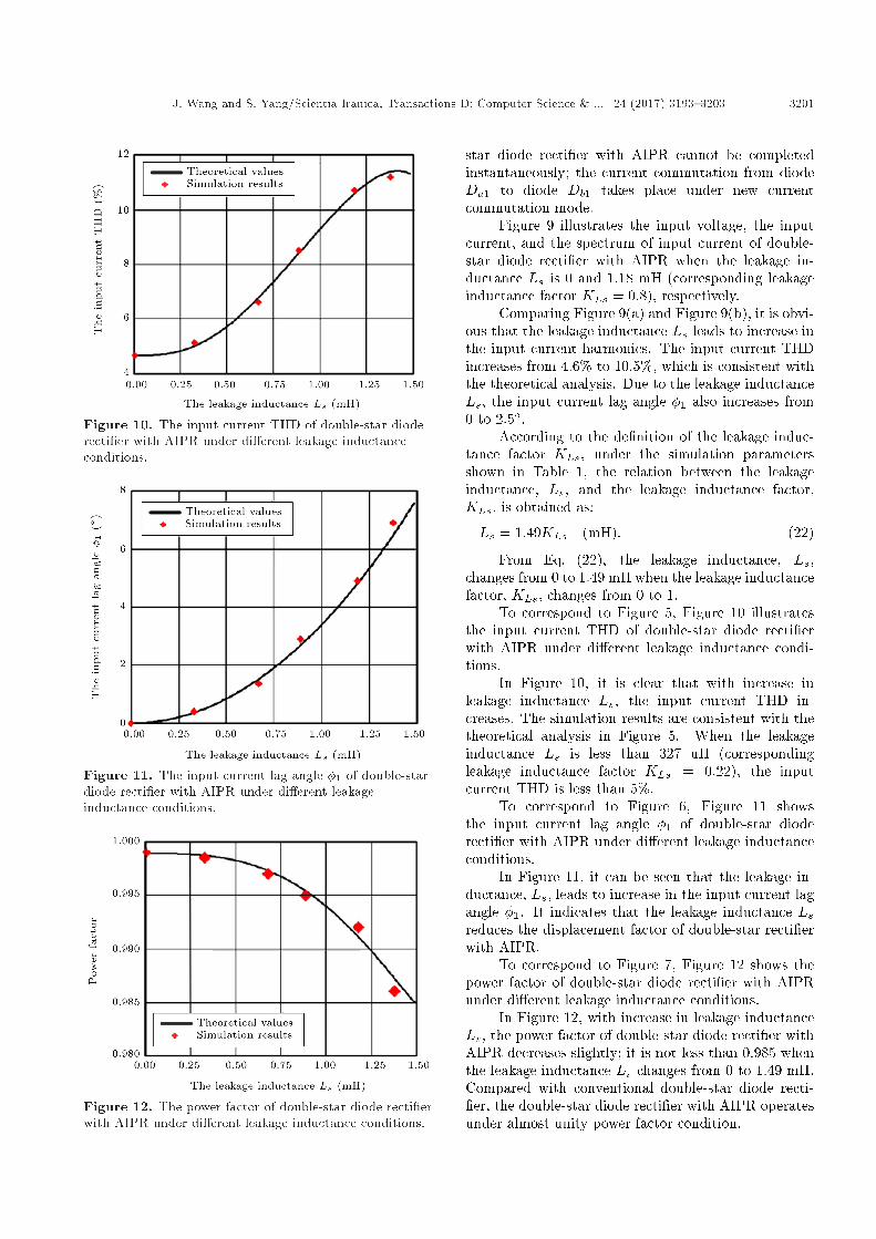
According to the de�nition of the leakage induc-tance factor KLs, under the simulation parametersshown in Table 1, the relation between the leakageinductance, Ls, and the leakage inductance factor,KLs, is obtained as:
Ls = 1:49KLs (mH): (22)
From Eq. (22), the leakage inductance, Ls,changes from 0 to 1.49 mH when the leakage inductancefactor, KLs, changes from 0 to 1.
To correspond to Figure 5, Figure 10 illustratesthe input current THD of double-star diode recti�erwith AIPR under di�erent leakage inductance condi-tions.
In Figure 10, it is clear that with increase inleakage inductance Ls, the input current THD in-creases. The simulation results are consistent with thetheoretical analysis in Figure 5. When the leakageinductance Ls is less than 327 uH (correspondingleakage inductance factor KLs = 0:22), the inputcurrent THD is less than 5%.
To correspond to Figure 6, Figure 11 showsthe input current lag angle �1 of double-star dioderecti�er with AIPR under di�erent leakage inductanceconditions.
In Figure 11, it can be seen that the leakage in-ductance, Ls, leads to increase in the input current lagangle �1. It indicates that the leakage inductance Lsreduces the displacement factor of double-star recti�erwith AIPR.
To correspond to Figure 7, Figure 12 shows thepower factor of double-star diode recti�er with AIPRunder di�erent leakage inductance conditions.
In Figure 12, with increase in leakage inductanceLs, the power factor of double-star diode recti�er withAIPR decreases slightly; it is not less than 0.985 whenthe leakage inductance Ls changes from 0 to 1.49 mH.Compared with conventional double-star diode recti-�er, the double-star diode recti�er with AIPR operatesunder almost unity power factor condition.
3202 J. Wang and S. Yang/Scientia Iranica, Transactions D: Computer Science & ... 24 (2017) 3193{3203
4. Conclusion
In this paper, the e�ects of leakage inductance oftransformer on the input line current of the double-star recti�er with AIPR are analyzed in depth. Thetheoretical analysis results indicate that the leakageinductance of transformer leads to increase in theinput current harmonics of the double-star recti�erwith AIPR, and the input current THD is greater than5% when the leakage inductance factor KLs is morethan 0.22. The leakage inductance of transformer alsoincreases the input current lag angle of the double-star recti�er with AIPR. It indicates that leakageinductance of transformer decreases the displacementfactor. In order to ensure that the double-star dioderecti�er with AIPR meets the requirements of the har-monics limitation standard and operates under almostunity displacement factor and power factor, the leakageinductance factor KLs of the double-star transformershould be less than 0.22.
Owing to the essence of the diode recti�ers,the same active current injection reduction method isused. The analysis method for the e�ects of leakageinductance of transformer on the input current in thispaper can be extended to analyze other diode recti�erswith active current injection circuit, such as 12-pulsediode recti�er with active current injection circuit.
References
1. Siebert, A., Troedson, A. and Ebner, S. \Ac to dcpower conversion now and in the future", IEEE Trans-actions on Industry Applications, 14(1), pp. 1876-1884(2013).
2. Singh, B., Gairola, S., Singh, B.N., Chandra, A. andAl-Haddad, K. \Multipulse AC-DC converters for im-proving power quality: a review", IEEE Transactionson Power Electronics, 23(1), pp. 260-281 (2008).
3. IEEE Guide for Recommended Control and ReactiveCompensation of Static Power Converters, IEEE Stan-dard 519 (1992).
4. Limitation of Emission of Harmonic Currents in Low-Voltage Power Supply Systems for Equipment WithRated Current Greater Than 16 A, IEC 61000-3-4(1998).
5. Swamy, M., Kume, T.J. and Takada, N. \A hybrid 18-pulse recti�cation scheme for diode front-end recti�erswith large DC bus capacitor", IEEE Transactions onIndustry Applications, 46(6), pp. 2484-2494 (2010).
6. Choi, S. \A three-phase unity-power-factor diode rec-ti�er with active input current shaping", IEEE Trans-actions on Industrial Electronics, 52(6), pp. 1711-1714(2005).
7. Maswood, AI. and Liu, FR. \A novel unity powerfactor input stage for AC drive applications", IEEETransactions on Power Electronics, 20(4), pp. 839-846(2005).
8. Tangtheerajaroonwong, W., Hatada, T. and Wada, K.\Design and performance of a transformerless shunthybrid �lter integrated into a three-phase diode recti-�er", IEEE Transactions on Power Electronics, 22(5),pp. 1882-1889 (2007).
9. Saidi, S., Abbassi, R. and Chebbi, S. \Virtual uxbased direct power control of shunt active �lter",Scientia Iranica. Transaction D, Computer Science &Engineering and Electrical Engineering, 21(6), pp. 99-109 (2014).
10. Le Roux, A.D., Mouton, H. du T. and Akagi, H.\DFT-based repetitive control of a series active �l-ter integrated with a 12-pulse diode recti�er", IEEETransactions on Power Electronics, 24(6), pp. 1515-1521 (2009).
11. Akagi, H. and Isozaki, K. \A hybrid active �lterfor a three-phase 12-pulse diode recti�er used as thefront end of a medium-voltage motor drive", IEEETransactions on Power Electronics, 27(1), pp. 69-77(2012).
12. Villablanca, M.E., Nadal, J.I. and Bravo, M.A. \A 12-pulse AC-DC recti�er with high-quality input/outputwaveforms", IEEE Transactions on Power Electronics,22(5), pp. 1875-1881 (2007).
13. Fukuda, S., Ohta, M. and Iwaji, Y. \An auxiliary-supply-assisted harmonic reduction scheme for 12-pulse diode recti�ers", IEEE Transactions on PowerElectronics, 23(3), pp. 1270-1277 (2008).
14. Singh, B., Bhuvaneswari, G., Garg, V. and Gairola, S.\Harmonic mitigation in AC-DC converters for vectorcontrolled induction motor drives", IEEE Transactionson Energy Conversion, 22(3), pp. 637-646 (2007).
15. Mino, K., Gong, G. and Kolar, J.W. \Novel hybrid 12-pulse boost-type recti�er with controlled output volt-age", IEEE Transactions on Aerospace and ElectronicSystem, 41(3), pp. 1008-1018 (2005).
16. Biela, J., Hassler, D. and Schoenberger, J. \Closed-loop sinusoidal input-current shaping of 12-pulse au-totransformer recti�er unit with impressed outputvoltage", IEEE Transactions on Power Electronics,26(1), pp. 249-259 (2011).
17. Araujo-Vargas, I., Forsyth, A.J. and Chivite-Zabalza,F.J. \High perfor-mance multi-pulse recti�er withsingle transistor active injection", IEEE Transactionson Power Electronics, 23(3), pp. 1299-1308 (2008).
18. Lee, BS., Hahn, J. and Enjeti, PN. \A robust three-phase active power-factor-correction and harmonic re-duction scheme for high power", IEEE Transactionson Industry Electronics, 46(3), pp. 483-493 (1999).
19. Choi, S., Enjeti, P.N., Lee, H.H. and Pitel, I.J. \Anew active inter-phase reactor for 12-pulse recti�ersprovides clean power utility interface", IEEE Transac-tions on Industry Applications, 32(6), pp. 1304-1311(1996).
20. Bai, S. and Lukic, S.M. \New method to achieve ACharmonic elimination and energy storage integration
J. Wang and S. Yang/Scientia Iranica, Transactions D: Computer Science & ... 24 (2017) 3193{3203 3203
for 12-pulse diode recti�ers", IEEE Transactions onIndustrial Electronics, 60(7), pp. 2547-2554 (2013).
21. Young, C.M., Chen, M.H. and Lai, C.H. \A novelactive interphase transformer scheme to achieve three-phase line current balance for 24-Pulse converter",IEEE Transactions on Power Electronics, 27(4), pp.1719-1731 (2012).
22. Wang, J., Yang, S., Yang, W. and Li, Y. \A low har-monic double star recti�er with current injection at DCside", International Power Electronics and Applicationand Exposition Conference, Shanghai, China, pp. 909-913 (2014).
23. Meng, F., Yang, S., Yang, W. and Gao, L. \Activeharmonic reduction for 12-pulse diode bridge recti�erat DC side with two-stage auxiliary circuit", IEEETransactions on Industrial Information, 11(1), pp. 64-73 (2015).
24. Young, C.M., Wu, S.F. and Yeh, W.S. \A DC-side current injection method for improving AC linecondition applied in the 18-pulse converter system",IEEE Transactions on Power Electronics, 29(1), pp.99-109 (2014).
25. Mao, L., Ren, X., Ruan, X. and Jiang, L. \Researchof the current-injection-based P-type 12-pulse ATRU",International Power Electronics and Motion ControlConference, Harbin, China, pp. 41-46 (2012).
26. Wang, M. and Zhang, F. \12-pulse auto-transformerrecti�er with harmonic current injection for non-grid-
connected wind power applications", World Non-Grid-Connected Wind Power and Energy Conference, Nan-jing, China, pp. 226-230 (2009).
Biographies
Jingfang Wang was born in Hebei, China, in 1984.He received the BS degree in Automation from YanshanUniversity, Qinhuangdao, China, in 2008 and theMS degree in Electrical Engineering from the HarbinEngineering University, Harbin, China, in 2012. Since2012, he has been working towards the PhD degreein Electrical Engineering at the Harbin Institute ofTechnology, Harbin, China.
His research interests include high power convert-ers and harmonics compensation.
Shiyan Yang was born in Heilongjiang, China, in1962. He received the BS and MS degrees in ElectricalEngineering and the PhD degree in Welding Engineer-ing from the Harbin Institute of Technology, Harbin,China, in 1984, 1989, and 1998, respectively.
He is currently a professor and supervisor of Doc-toral Candidates at the Harbin Institute of Technology.He has published over 60 papers. His research interestsinclude high-power special type power supply and itsapplication, energy storage system and its equilibrium,and fundamental theory of �nity power supply driveand key commonsense problem.


![Proxima Centaur™ EF Control Unit - Caldertech...Input Frequency 40 - 60Hz Input Current [Max. A] 16A Input Power 3kW Output Voltage [Vac RMS] 8 - 48v Output Current [Continuous.](https://static.fdocuments.us/doc/165x107/6132fe13dfd10f4dd73acd61/proxima-centaura-ef-control-unit-caldertech-input-frequency-40-60hz-input.jpg)