DZ7 Moulded Case Circuit Breakers · User Centric Innovation The dsine DZ range of Moulded Case...
18
User Centric Innovation Moulded Case Circuit Breakers DZ 7
Transcript of DZ7 Moulded Case Circuit Breakers · User Centric Innovation The dsine DZ range of Moulded Case...
User Centric Innovation
Moulded Case Circuit BreakersDZ7

A technology idea often forms the foundation of innovation in a product and the success of its outcome is determined by the users’ experience. Talking to customers and taking their feedback gives an assurance that the innovation would meet the expected and even aspired results. The dsine DZ range is an outcome of users’ feedback that has been recorded, analysed and incorporated in its design and development journey.

About L&T Electrical & Automation
L&T Electrical & Automation (E&A) is a part of US $17 billion Larsen & Toubro that is engaged in technology, engineering, construction, manufacturing and financial services with operations in over 30 countries worldwide. Its business comprises low and medium voltage switchgear products, electrical systems, energy meters, wiring accessories and automation solutions. E&A’s in-house design and development centre for switchgear promotes a culture of collaboration and experimentation that facilitates innovation and creation of intellectual property.
The customer-focus philosophy of E&A has led to setting up of a wide network of channel partners along with manufacturing operations in Navi Mumbai, Ahmednagar, Vadodara, Coimbatore and Mysore in India as well as in Saudi Arabia, Jebel Ali (Dubai), Kuwait, Malaysia, Indonesia and the UK.
User Centric Innovation
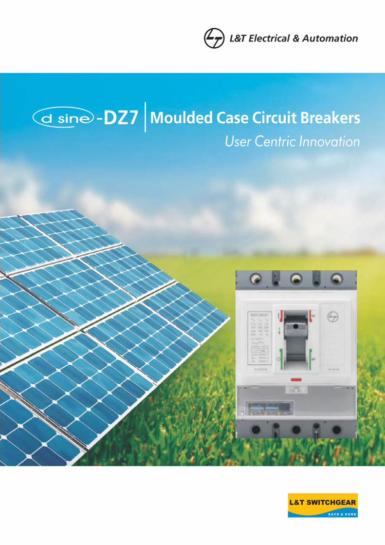
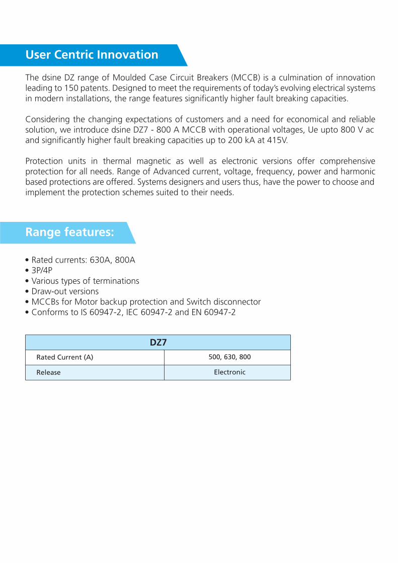
The dsine DZ range of Moulded Case Circuit Breakers (MCCB) is a culmination of innovation leading to 150 patents. Designed to meet the requirements of today’s evolving electrical systems in modern installations, the range features significantly higher fault breaking capacities.
Considering the changing expectations of customers and a need for economical and reliable solution, we introduce dsine DZ7 - 800 A MCCB with operational voltages, Ue upto 800 V ac and significantly higher fault breaking capacities up to 200 kA at 415V.
Protection units in thermal magnetic as well as electronic versions offer comprehensive protection for all needs. Range of Advanced current, voltage, frequency, power and harmonic based protections are offered. Systems designers and users thus, have the power to choose and implement the protection schemes suited to their needs.
• Rated currents: 630A, 800A• 3P/4P• Various types of terminations• Draw-out versions• MCCBs for Motor backup protection and Switch disconnector• Conforms to IS 60947-2, IEC 60947-2 and EN 60947-2
500, 630, 800
Electronic
Rated Current (A)
Release
DZ7
Range features:
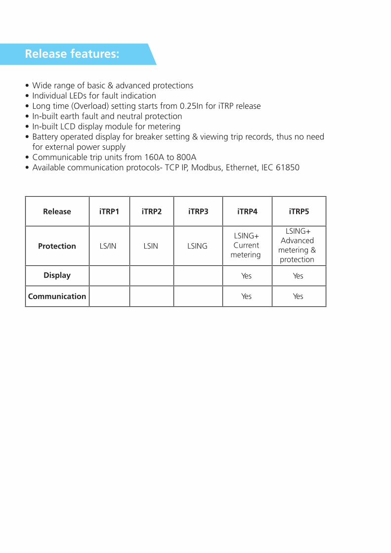
• Wide range of basic & advanced protections• Individual LEDs for fault indication• Long time (Overload) setting starts from 0.25In for iTRP release• In-built earth fault and neutral protection• In-built LCD display module for metering• Battery operated display for breaker setting & viewing trip records, thus no need
for external power supply• Communicable trip units from 160A to 800A• Available communication protocols- TCP IP, Modbus, Ethernet, IEC 61850
Release
Protection
Display
Communication
iTRP1 iTRP2 iTRP3 iTRP4 iTRP5
LS/IN LSIN LSING
LSING+ Current
metering
LSING+ Advanced
metering & protection
Yes Yes
Yes Yes
Release features:
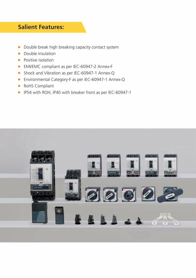
Double break high breaking capacity contact system
Double insulation
Positive isolation
EMI/EMC compliant as per IEC-60947-2 Annex-F
Shock and Vibration as per IEC-60947-1 Annex-Q
Environmental Category-F as per IEC-60947-1 Annex-Q
RoHS Compliant
IP54 with ROH, IP40 with breaker front as per IEC-60947-1
Salient Features:
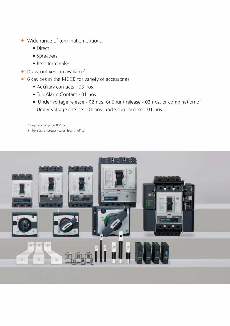
Wide range of termination options:
• Direct
• Spreaders
• Rear terminals*
* - Applicable up to 690 V a.c.
# - For details contact nearest branch of?ce
# Draw-out version available
6 cavities in the MCCB for variety of accessories
• Auxiliary contacts - 03 nos.
• Trip Alarm Contact - 01 nos.
• Under voltage release - 02 nos. or Shunt release - 02 nos. or combination of
Under voltage release - 01 nos. and Shunt release - 01 nos.

Electronic releases:
iTRP 1
• Wide range of overload setting from 0.25In
• Adjustable trip class
• Neutral overload protection
• Short circuit setting with delay or instantaneous option
• Thermal memory defeat
• Provision for release testing
or Instantaneous
iTRP1
OverLoad (Phase)
OverLoad (Neutral)
Short Circuit
630, 800
DZ7
0.25 to 1 x In (in step of 0.05)
10s at 6Ir, 3s at 6Ir , 10s at 7.2 Ir, 3s at 7.2Ir
ON/OFF
ON/OFF
OFF / 1.0 x Ir
As per Overload Curve Setting
ON/OFF
1.5 to 10 x Ir (in steps of 0.5) for 630A
1.5 to 8 x Ir (in steps of 0.5) for 800A2
As per I t curve /150ms
ON/OFF
1.5 to 10 x Ir (in steps of 0.5) for 630A
1.5 to 8 x Ir (in steps of 0.5) for 800A
Rated Current
Frame
Current Setting Ir (Ir = x In)
Time delay, Tr (Inverse)
Protection Mode
Thermal Memory
Current Setting In (In = x Ir)
Time delay, Tr (Inverse)
Protection Mode
Current Setting Id (Isd = x Ir)
Time delay, Tsd
2I t
Current Setting Ii (Ii = x In)
LS / IN
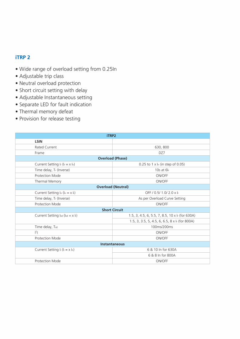
iTRP 2
• Wide range of overload setting from 0.25In
• Adjustable trip class
• Neutral overload protection
• Short circuit setting with delay
• Adjustable Instantaneous setting
• Separate LED for fault indication
• Thermal memory defeat
• Provision for release testing
Overload (Phase)
Short Circuit
Overload (Neutral)
iTRP2
Instantaneous
LSIN
Rated Current
Frame
Current Setting Ir (Ir = x In)
Time delay, Tr (Inverse)
Protection Mode
Thermal Memory
Current Setting In (In = x Ir)
Time delay, Tr (Inverse)
Protection Mode
Current Setting Isd (Isd = x Ir)
Time delay, Tsd
2I t
Protection Mode
Current Setting Ii (Ii = x In)
Protection Mode
630, 800
DZ7
0.25 to 1 x In (in step of 0.05)
10s at 6Ir
ON/OFF
ON/OFF
OFF / 0.5/ 1.0/ 2.0 x Ir
As per Overload Curve Setting
ON/OFF
1.5, 3, 4.5, 6, 5.5, 7, 8.5, 10 x Ir (for 630A)
1.5, 3, 3.5, 5, 4.5, 6, 6.5, 8 x Ir (for 800A)
100ms/200ms
ON/OFF
ON/OFF
6 & 10 In for 630A
6 & 8 In for 800A
ON/OFF

iTRP 3
• Wide range of overload setting from 0.25In
• Adjustable trip class
• Neutral overload protection
• Short circuit setting with delay
• Adjustable Instantaneous setting
• Separate LED for fault indication
• In-built earth fault protection
• Thermal memory defeat
• Provision for release testing
Overload (Phase)
Short Circuit
Overload (Neutral)
Earth Fault
iTRP3
LSIN
Frame
Current Setting Ir (Ir = x In)
Time delay, Tr (Inverse)
Protection Mode
Thermal Memory
Current Setting In (In = x Ir)
Time delay, Tr (Inverse)
Protection Mode
Current Setting Isd (Isd = x Ir)
Time delay, Tsd
2I t
Protection Mode
Current Setting Ii (Ii = x In)
Protection Mode
Current Setting Ig (Ig = x In)
Time delay, Tg
Protection Mode
Rated Current, In 630, 800
DZ7
0.25 to 1 x In (in step of 0.05)
10s at 6Ir
ON/OFF
ON/OFF
OFF / 0.5/ 1.0/ 2.0 x Ir
As per Overload Curve Setting
ON/OFF
1.5, 3, 4.5, 6, 5.5, 7, 8.5, 10 x Ir (for 630A)
1.5, 3, 3.5, 5, 4.5, 6, 6.5, 8 x Ir (for 800A)v
100ms/200ms
ON/OFF
ON/OFF
6 & 10 In for 630A
6 & 8 In for 800A
ON/OFF
0.2, 0.4, 0.5, 0.7
100ms/200ms
ON/OFF
Instantaneous

Technical Datasheet
Current Range In(A)
Release
Poles
Impulse Withstand Voltage Uimp(kV)
Rated Operational Voltage Ue(VAC) (MAX) @ 50/60Hz
Rated Insulation Voltage Ui(V AC)
Utilization Category
Standard
Rated Short Circuit Breaking Capacity Icu(kA) @ 800V
Rated Short Circuit Breaking Capacity Ics(kA) @ 800V
Making Capacity (kA) @ 800VAC
Operating Frequency (Hz)
Fingerproof Terminals
Suitable for isolation
IP Class
Pollution Degree
Load-line bias
Ambient temperature
Storage temperature
Mounting positions in vertical plane
Weight(kg) 3P/4P
Mechanical
Electrical @ 415 V AC :630A/800A
Electrical @ 800 V AC :630A/800A
3 Pole
4 Pole
Auxiliary Contact
Trip Alarm Contact
Shunt Release
Under Voltage Release
Rotary Operating Mechanism(Direct/Extended)
Mechanical Interlock Kit
Spreader Terminals
500/630/800
Electronic
3P/4P
8
800
1000
A
IS 60947-2, IEC 60947-2, EN 60947-2
36
30
75.6
20000
5000
2500
50/60
with terminal shrouds
Yes
IP40 from front (for panel cutout area)
III
No
O O-5 C to 55 C
O O-15 C to 70 C
OVertical & 90 both directions
180*250*105
240*250*105
6.9/8.9
03 Aux
01 TAC
�
�
�
TYPE DZ7 - 800Y
Dimensions(W*H*D)(mm)
Life
02 UV or 02 Shunt or 1UV+1Shunt
Internal Accessories
External Accessories
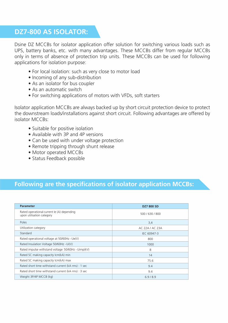
DZ7-800 AS ISOLATOR:
Dsine DZ MCCBs for isolator application offer solution for switching various loads such as UPS, battery banks, etc. with many advantages. These MCCBs differ from regular MCCBs only in terms of absence of protection trip units. These MCCBs can be used for following applications for isolation purpose:
• For local isolation: such as very close to motor load • Incoming of any sub-distribution • As an isolator for bus coupler • As an automatic switch • For switching applications of motors with VFDs, soft starters
Isolator application MCCBs are always backed up by short circuit protection device to protect the downstream loads/installations against short circuit. Following advantages are offered by isolator MCCBs:
• Suitable for positive isolation • Available with 3P and 4P versions • Can be used with under voltage protection • Remote tripping through shunt release • Motor operated MCCBs • Status Feedback possible
Following are the specifications of isolator application MCCBs:
DZ7 800 SD
3,4
AC 22A / AC 23A
IEC 60947-3
800
1000
8
14
75.6
9.4
9.4
6.9 / 8.9
500 / 630 / 800
Parameter
Poles
Utilization category
Standard
Rated operational voltage at 50/60Hz - Ue(V)
Rated Insulation Voltage 50/60Hz - Ui(V)
Rated impulse withstand voltage 50/60Hz - Uimp(kV)
Rated SC making capacity Icm(kA) min
Rated SC making capacity Icm(kA) max
Rated short time withstand current (kA rms) : 1 sec
Rated short time withstand current (kA rms) : 3 sec
Weight 3P/4P MCCB (kg)
Rated operational current (A) dependingupon utilisation category
Ie

Derating Factor at various Ambient Temperatures (I )1
OUpto 40 C
1
O 50 C
1
O60 C
0.95
O70 C
0.85
Altitude Correction Factors
Altitude (m)Rated Continuous
Current (In)Rated Voltage (V)
2000 & below 1.00 1.00
2500 0.99 0.95
4000 0.95 0.80
Altitude Correction Factors
Altitude does not significantly affect circuit breaker characteristics up to 2000m.Above this altitude, it is necessary to take into account the decrease in the dielectric strength and cooling capacity of air.Altitude may reduce Rated Impulse Withstand and Insulation Voltage too.
Ambient Temperature Correction
30 35 40 45 50 55 60 65 70 75
600
610
620
630
640
650
660
670
680
690
700
710
720
730
740
750
760
770
780
790
800
810
820
830
840
850
DZ7 800Y (800A)
DZ7 800Y (630A)
Derating Chart for Dz7
OT ( C)
Iu (
A)
I2T
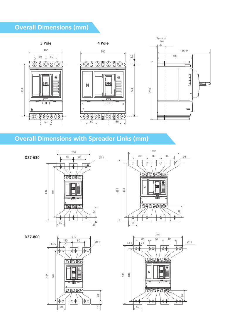
Overall Dimensions (mm)
Overall Dimensions with Spreader Links (mm)
DZ7-800
DZ7-630
180
60 60
224
60
240
13.2
224
60 30
TerminalLevel
27
155.4*
105
250
3 Pole 4 Pole
210
80 80
43
4
40
4
90
1550
290
80 80 80Ø11 Ø11
43
4
404
50
90
210
8080
2313.5Ø11
43
4
40
4
50
90
15
290
80 80 80
13.5 23 Ø11
43
4
40
4
50
90
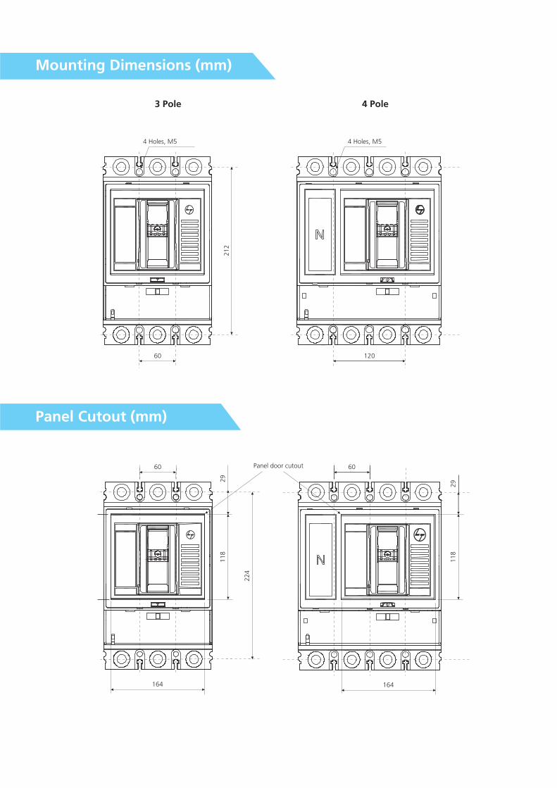
Mounting Dimensions (mm)
Panel Cutout (mm)
3 Pole 4 Pole
4 Holes, M5
21
2
60
4 Holes, M5
120
60
29
11
8
22
4
164
Panel door cutout 60
164
11
82
9
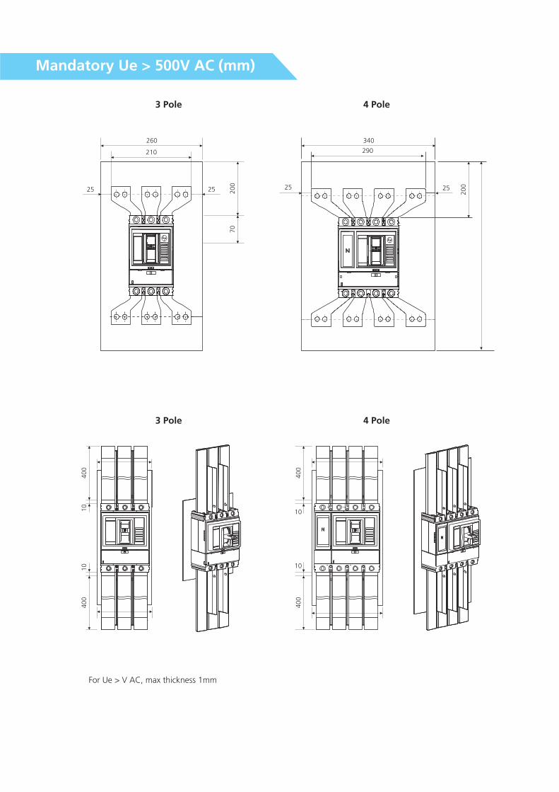
Mandatory Ue > 500V AC (mm)
For Ue > V AC, max thickness 1mm
3 Pole 4 Pole
3 Pole 4 Pole
260
210
25 200
25
70
340
290
25
200
10
40
01
04
00
40
0
10
10
40
0
25

Energy-Limiting Curve for d sine-DZ7 @ 800V
Current-Limiting Curve for d sine-DZ7@ 800V
I-rms (kA)1 10 50 100 1000
5
10
15
20
25
3035404550
500
I-p
ea
k (
kA
)
I Prospective
DZ7 -630 /800Y
I-rms (kA)1 10 100 1000
0.1
0.50
10.0
0.600.700.800.90
1.0
2.00
26
Let T
hro
ugh E
nerg
y - A
*s x
10
50
YDZ7 -630 /800

Product improvement is a continuous process. For the latest information and special applications, please contact any of our offices listed here.Product photographs shown are for representative purpose only.
Larsen & Toubro Limited, Electrical Standard Products
Powai Campus, Mumbai 400 072
Customer Interaction Center (CIC)
BSNL / MTNL (toll free) : 1800 233 5858 Reliance (toll free) : 1800 200 5858
Tel : 022 6774 5858
E-mail : [email protected] / Website www.Lntebg.com
Registered Office: L&T House, N. M. Marg, Ballard Estate, Mumbai 400 001, INDIA CIN: L99999MH1946PLC004768
SP 5
0678
R2