DZ - Farnell element14 · Special-purpose Basic Switch DZ 91 Engineering Data Mechanical Durability...
8
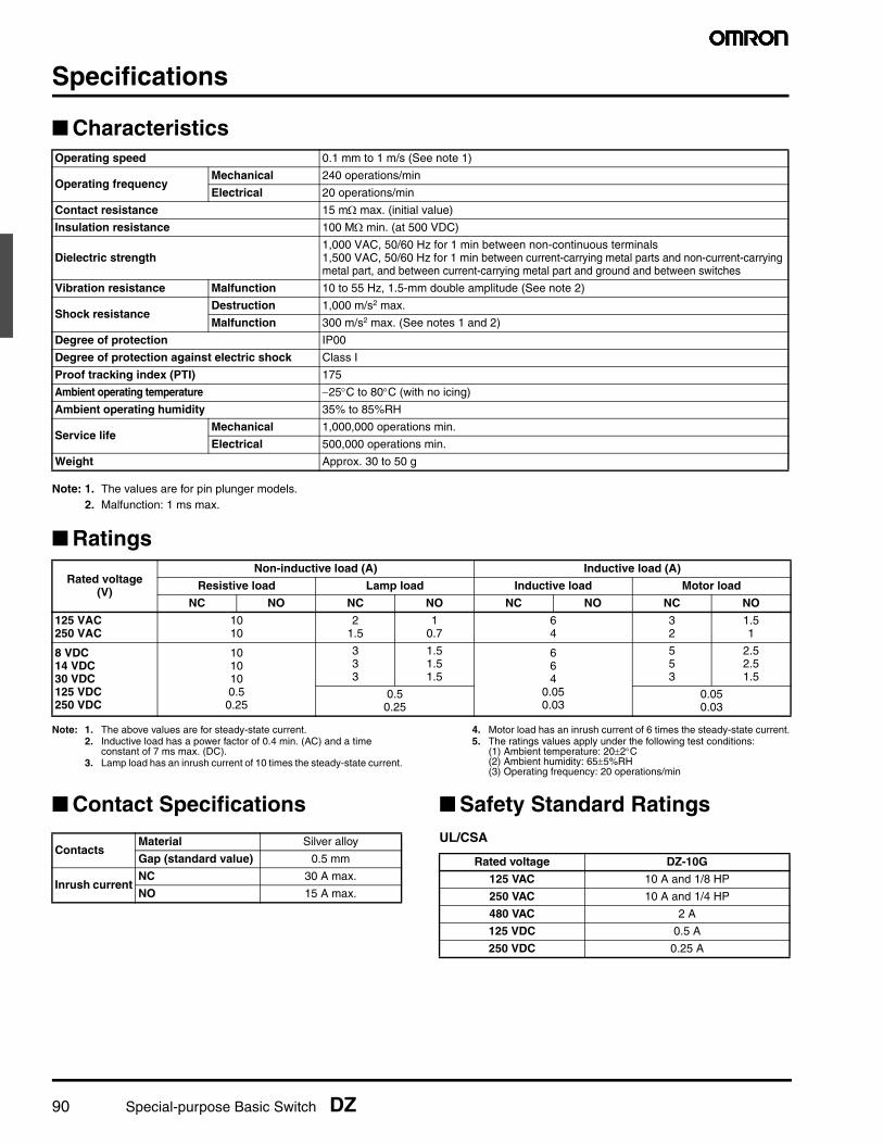
Special-purpose Basic Switch DZ 89 Special-purpose Basic Switch DZ DPDT Basic Switch for Two Independent Circuit Control • Incorporates two completely independent built-in switches. • Ideal for switching the circuits operating on two different voltages, and for controlling two independent circuits. • Interchangeable with OMRON Z Basic Switches, as both switches are identical in mounting hole dimensions, mounting pitch and pin plunger position. Ordering Information Model Number Legend Terminal Solder terminal (-1A) Screw terminal (-B) Actuator OT (min.) Model Model Pin plunger 0.13 mm DZ-10G-1A DZ-10G-1B Hinge lever 1.6 mm DZ-10GW-1A DZ-10GW-1B 0.4 mm DZ-10GV-1A DZ-10GV-1B Short hinge roller lever 0.9 mm DZ-10GW22-1A DZ-10GW22-1B 0.13 mm DZ-10GV22-1A DZ-10GV22-1B Hinge roller lever 1.2 mm DZ-10GW2-1A DZ-10GW2-1B 0.26 mm DZ-10GV2-1A DZ-10GV2-1B DZ-10 G - 1 3 2 1 5 4 1. Ratings 10: 10 A (250 VAC) 2. Contact Gap G: 0.5 mm 3. Actuator None: Pin plunger Low OT Levers: V: Hinge lever V22: Short hinge roller lever V2: Hinge roller lever High OT Levers: W: Hinge lever W22: Short hinge roller lever W2: Hinge roller lever 4. Contact Form 1: DPDT 5. Terminals A: Solder terminal B: Screw terminal
Transcript of DZ - Farnell element14 · Special-purpose Basic Switch DZ 91 Engineering Data Mechanical Durability...
Special-purpose Basic Switch DZ 89
Special-purpose Basic Switch
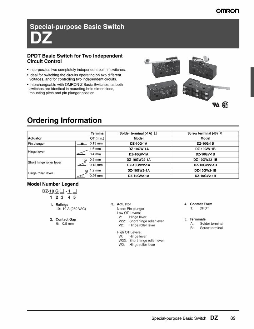
DZDPDT Basic Switch for Two Independent Circuit Control
• Incorporates two completely independent built-in switches.• Ideal for switching the circuits operating on two different
voltages, and for controlling two independent circuits.
• Interchangeable with OMRON Z Basic Switches, as both switches are identical in mounting hole dimensions, mounting pitch and pin plunger position.
Ordering Information
Model Number Legend
Terminal Solder terminal (-1A) Screw terminal (-B)
Actuator OT (min.) Model Model
Pin plunger 0.13 mm DZ-10G-1A DZ-10G-1B
Hinge lever1.6 mm DZ-10GW-1A DZ-10GW-1B
0.4 mm DZ-10GV-1A DZ-10GV-1B
Short hinge roller lever0.9 mm DZ-10GW22-1A DZ-10GW22-1B
0.13 mm DZ-10GV22-1A DZ-10GV22-1B
Hinge roller lever1.2 mm DZ-10GW2-1A DZ-10GW2-1B
0.26 mm DZ-10GV2-1A DZ-10GV2-1B
DZ-10 G - 1 321 54
1. Ratings 10: 10 A (250 VAC)
2. Contact Gap G: 0.5 mm
3. Actuator None: Pin plunger Low OT Levers: V: Hinge lever V22: Short hinge roller lever V2: Hinge roller lever
High OT Levers: W: Hinge lever W22: Short hinge roller lever W2: Hinge roller lever
4. Contact Form 1: DPDT
5. Terminals A: Solder terminal B: Screw terminal
90 Special-purpose Basic Switch DZ
Specifications
■ Characteristics
Note: 1. The values are for pin plunger models. 2. Malfunction: 1 ms max.
■ Ratings
Note: 1. The above values are for steady-state current.2. Inductive load has a power factor of 0.4 min. (AC) and a time
constant of 7 ms max. (DC).3. Lamp load has an inrush current of 10 times the steady-state current.
4. Motor load has an inrush current of 6 times the steady-state current.5. The ratings values apply under the following test conditions:
(1) Ambient temperature: 20±2°C(2) Ambient humidity: 65±5%RH(3) Operating frequency: 20 operations/min
■ Contact Specifications ■ Safety Standard RatingsUL/CSA
Operating speed 0.1 mm to 1 m/s (See note 1)
Operating frequencyMechanical 240 operations/min
Electrical 20 operations/min
Contact resistance 15 mΩ max. (initial value)
Insulation resistance 100 MΩ min. (at 500 VDC)
Dielectric strength1,000 VAC, 50/60 Hz for 1 min between non-continuous terminals1,500 VAC, 50/60 Hz for 1 min between current-carrying metal parts and non-current-carrying metal part, and between current-carrying metal part and ground and between switches
Vibration resistance Malfunction 10 to 55 Hz, 1.5-mm double amplitude (See note 2)
Shock resistanceDestruction 1,000 m/s2 max.
Malfunction 300 m/s2 max. (See notes 1 and 2)
Degree of protection IP00
Degree of protection against electric shock Class I
Proof tracking index (PTI) 175
Ambient operating temperature −25°C to 80°C (with no icing)
Ambient operating humidity 35% to 85%RH
Service lifeMechanical 1,000,000 operations min.
Electrical 500,000 operations min.
Weight Approx. 30 to 50 g
Rated voltage(V)
Non-inductive load (A) Inductive load (A)
Resistive load Lamp load Inductive load Motor load
NC NO NC NO NC NO NC NO
125 VAC250 VAC
1010
21.5
10.7
64
32
1.51
8 VDC14 VDC30 VDC125 VDC250 VDC
1010100.5
0.25
333
1.51.51.5
664
0.050.03
553
2.52.51.5
0.50.25
0.050.03
ContactsMaterial Silver alloy
Gap (standard value) 0.5 mm
Inrush currentNC 30 A max.
NO 15 A max.
Rated voltage DZ-10G
125 VAC 10 A and 1/8 HP
250 VAC 10 A and 1/4 HP
480 VAC 2 A
125 VDC 0.5 A
250 VDC 0.25 A
Special-purpose Basic Switch DZ 91
Engineering Data
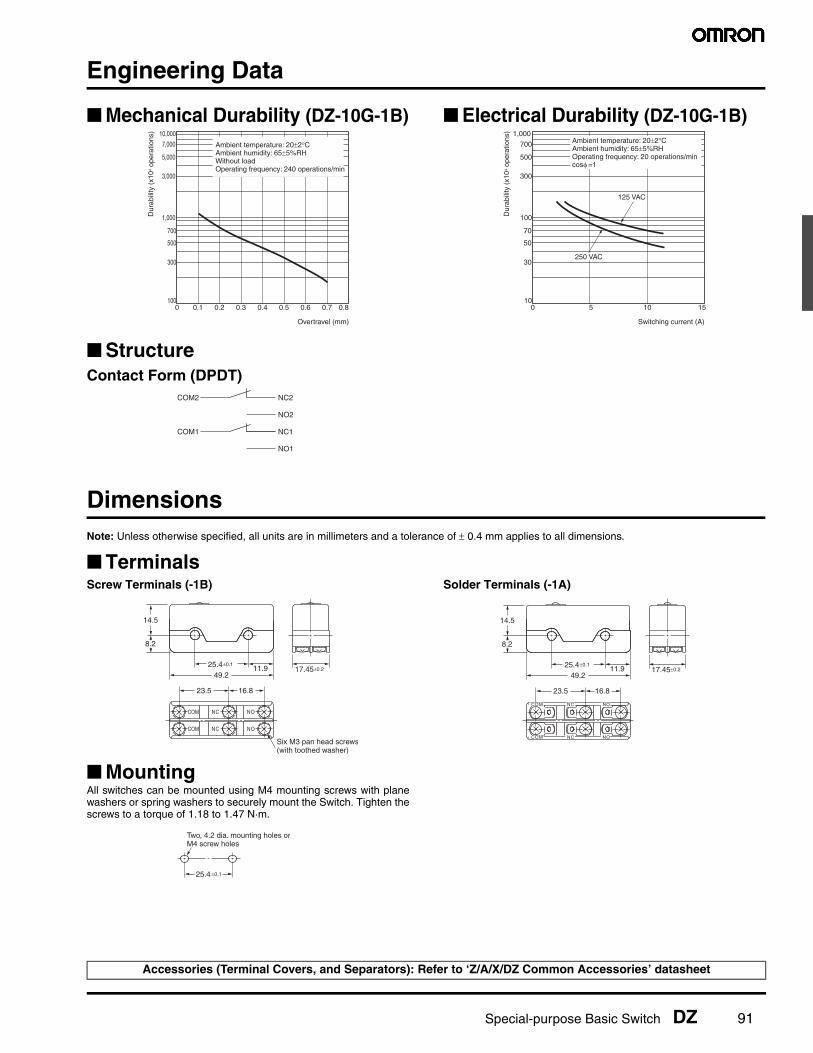
■ Mechanical Durability (DZ-10G-1B) ■ Electrical Durability (DZ-10G-1B)
■ StructureContact Form (DPDT)
DimensionsNote: Unless otherwise specified, all units are in millimeters and a tolerance of ± 0.4 mm applies to all dimensions.
■ TerminalsScrew Terminals (-1B) Solder Terminals (-1A)
■ MountingAll switches can be mounted using M4 mounting screws with planewashers or spring washers to securely mount the Switch. Tighten thescrews to a torque of 1.18 to 1.47 N·m.
10,000
7,000
5,000
3,000
1,000
700
500
300
1000 0.1 0.2 0.3 0.4 0.5 0.6 0.7 0.8
Overtravel (mm)
Dur
abili
ty (
x104 o
pera
tions
)Ambient temperature: 20±2°CAmbient humidity: 65±5%RHWithout loadOperating frequency: 240 operations/min
1,000
700
500
300
100
70
50
30
100 5 10 15
Switching current (A)
250 VAC
125 VAC
Dur
abili
ty (
x104 o
pera
tions
)
Ambient temperature: 20±2°CAmbient humidity: 65±5%RHOperating frequency: 20 operations/mincosφ =1
COM2 NC2
NO2
COM1 NC1
NO1
COM NC NO
COM NC NO
17.45±0.225.4±0.1
11.949.2
8.2
14.5
23.5 16.8
Six M3 pan head screws(with toothed washer)
NC NOCOM
NC NOCOM
17.45±0.225.4±0.1
11.949.2
8.2
14.5
23.5 16.8
25.4 ±0.1
Two, 4.2 dia. mounting holes orM4 screw holes
Accessories (Terminal Covers, and Separators): Refer to ‘Z/A/X/DZ Common Accessories’ datasheet
92 Special-purpose Basic Switch DZ
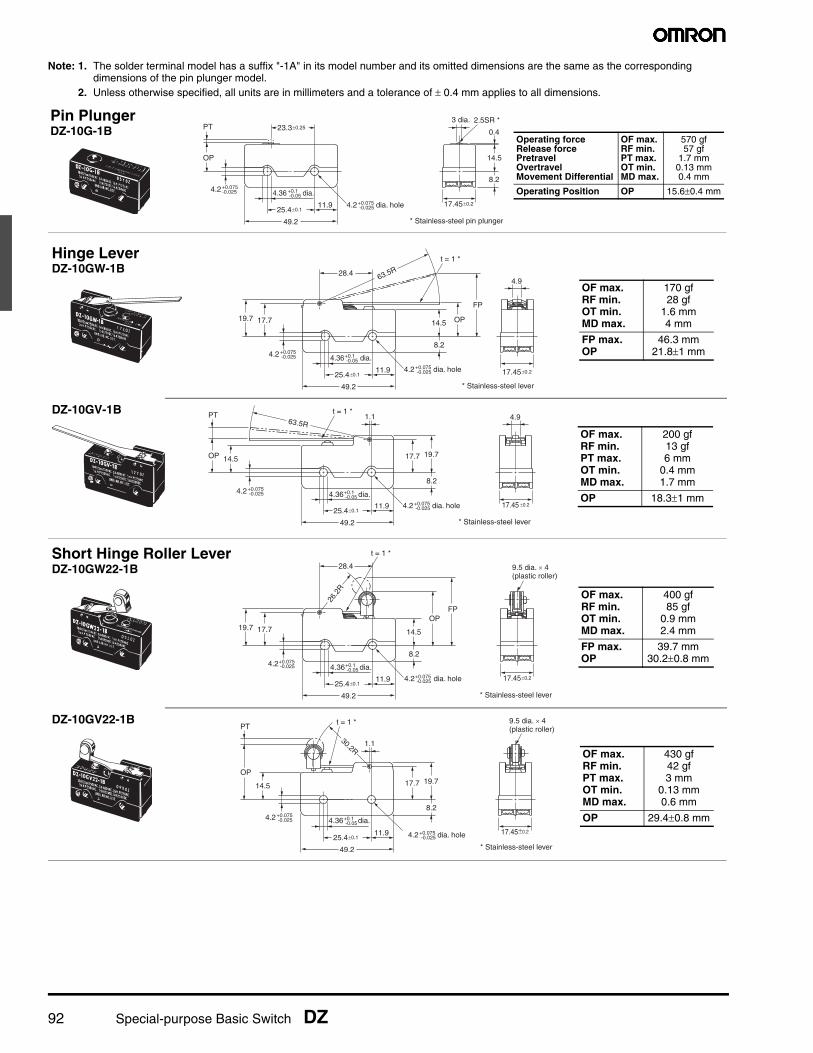
Note: 1. The solder terminal model has a suffix "-1A" in its model number and its omitted dimensions are the same as the corresponding dimensions of the pin plunger model.
2. Unless otherwise specified, all units are in millimeters and a tolerance of ± 0.4 mm applies to all dimensions.
4.2 dia. hole+0.075-0.025
4.36 dia.+0.1-0.05
4.2+0.075-0.025
23.3±0.25
25.4±0.111.9
49.2
17.45±0.2
PT
OP
3 dia. 2.5SR *
0.4
14.5
8.2
* Stainless-steel pin plunger
Pin PlungerDZ-10G-1B
Operating forceRelease forcePretravelOvertravelMovement Differential
OF max.RF min.PT max.OT min.MD max.
570 gf57 gf
1.7 mm0.13 mm0.4 mm
Operating Position OP 15.6±0.4 mm
28.4
25.4±0.111.9
49.2
17.45±0.2
17.719.714.5
FP
8.2
OP
4.9
* Stainless-steel lever
t = 1 *
63.5R
4.2 dia. hole+0.075-0.025
4.36 dia.+0.1-0.05
4.2+0.075-0.025
Hinge LeverDZ-10GW-1B
OF max.RF min.OT min.MD max.
170 gf28 gf
1.6 mm4 mm
FP max.OP
46.3 mm21.8±1 mm
17.45 ±0.2
4.9
* Stainless-steel lever
25.4±0.111.9
49.2
17.7
4.2 dia. hole+0.075-0.025
4.36 dia.+0.1-0.05
4.2+0.075-0.025
19.714.5
8.2
OP
PT t = 1 *63.5R
1.1DZ-10GV-1B
OF max.RF min.PT max.OT min.MD max.
200 gf13 gf6 mm
0.4 mm1.7 mm
OP 18.3±1 mm
4.2 dia. hole+0.075-0.025
4.36 dia.+0.1-0.05
4.2+0.075-0.025
28.4
25.4±0.111.9
49.2
17.45±0.2
17.719.714.5
FP
8.2
OP
9.5 dia. × 4(plastic roller)
* Stainless-steel lever
t = 1 *
26.2
R
Short Hinge Roller LeverDZ-10GW22-1B
OF max.RF min.OT min.MD max.
400 gf85 gf
0.9 mm2.4 mm
FP max.OP
39.7 mm30.2±0.8 mm
17.45±0.2
* Stainless-steel lever
4.2 dia. hole+0.075-0.025
4.36 dia.+0.1-0.05
25.4±0.111.9
49.2
17.7 19.714.5
8.2
OP
PT
4.2+0.075-0.025
t = 1 *
1.1
9.5 dia. × 4(plastic roller)
30.2R
DZ-10GV22-1B
OF max.RF min.PT max.OT min.MD max.
430 gf42 gf3 mm
0.13 mm0.6 mm
OP 29.4±0.8 mm
Special-purpose Basic Switch DZ 93
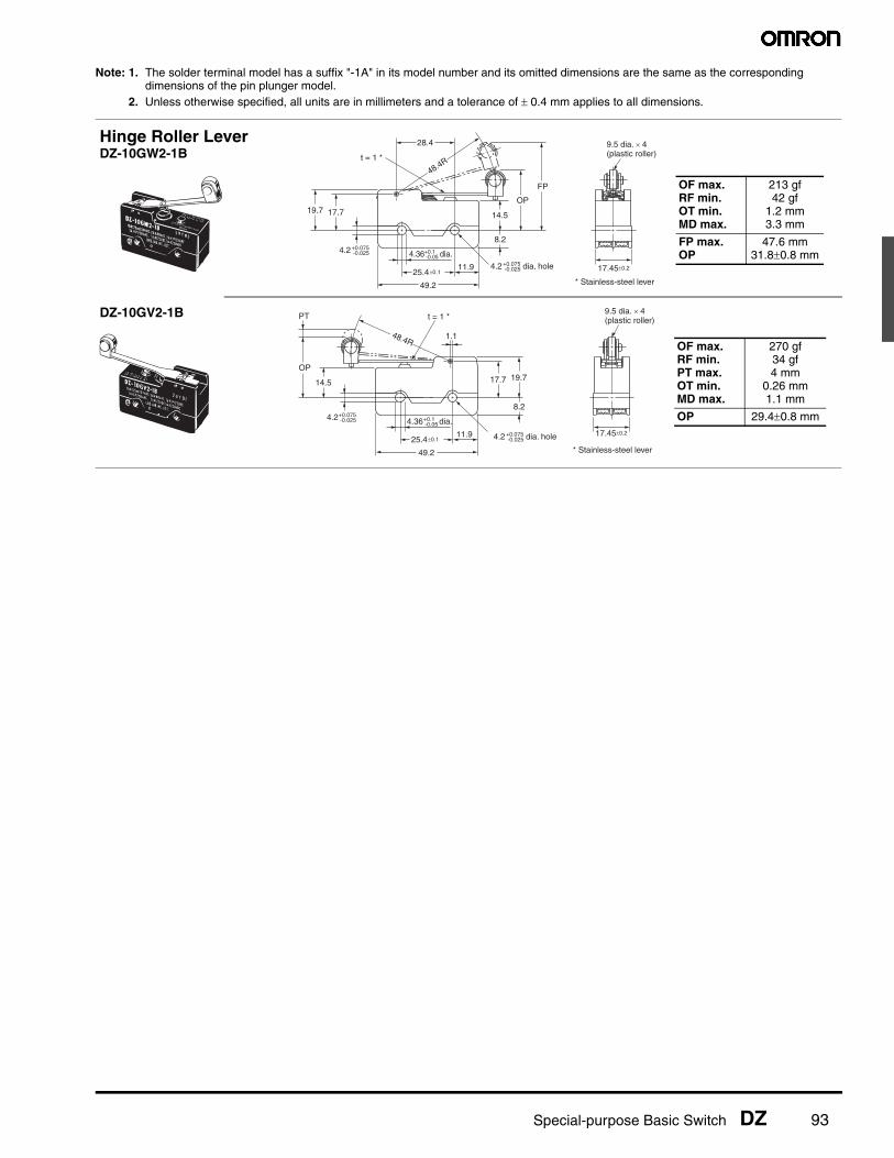
Note: 1. The solder terminal model has a suffix "-1A" in its model number and its omitted dimensions are the same as the corresponding dimensions of the pin plunger model.
2. Unless otherwise specified, all units are in millimeters and a tolerance of ± 0.4 mm applies to all dimensions.
28.4
25.4±0.111.9
49.2
17.45±0.2
17.719.714.5
FP
8.2
OP
9.5 dia. × 4(plastic roller)
* Stainless-steel lever
t = 1 *
48.4R
4.2 dia. hole+0.075-0.025
4.36 dia.+0.1-0.05
4.2+0.075-0.025
17.45±0.2
* Stainless-steel lever
4.2 dia. hole+0.075-0.025
4.36 dia.+0.1-0.05
25.4±0.111.9
49.2
17.7 19.714.5
8.2
OP
PT t = 1 *
1.1
9.5 dia. × 4(plastic roller)
48.4R
4.2+0.075-0.025
OF max.RF min.PT max.OT min.MD max.
270 gf34 gf4 mm
0.26 mm1.1 mm
OP 29.4±0.8 mm
Hinge Roller LeverDZ-10GW2-1B
OF max.RF min.OT min.MD max.
213 gf42 gf
1.2 mm3.3 mm
FP max.OP
47.6 mm31.8±0.8 mm
DZ-10GV2-1B
94 Special-purpose Basic Switch DZ
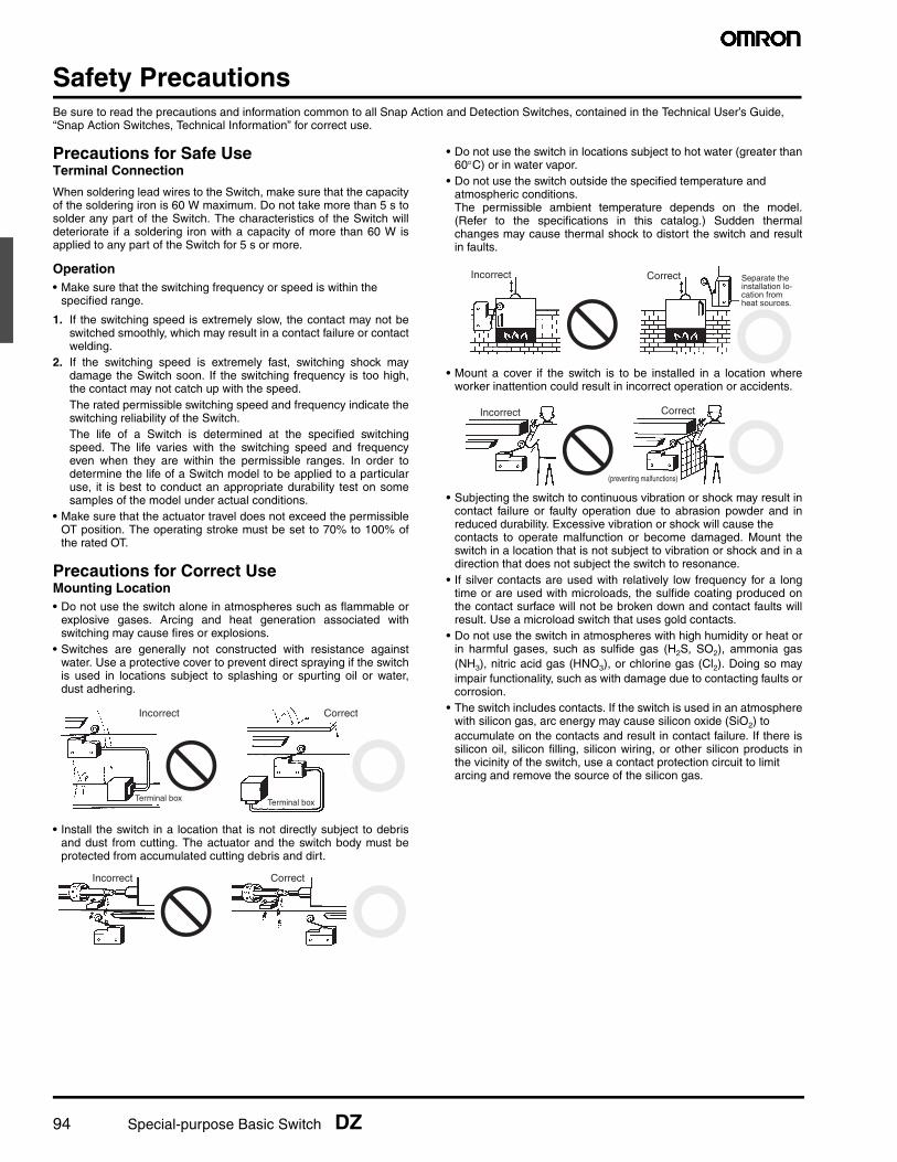
Safety PrecautionsBe sure to read the precautions and information common to all Snap Action and Detection Switches, contained in the Technical User’s Guide, “Snap Action Switches, Technical Information” for correct use.
Precautions for Safe UseTerminal Connection
When soldering lead wires to the Switch, make sure that the capacityof the soldering iron is 60 W maximum. Do not take more than 5 s tosolder any part of the Switch. The characteristics of the Switch willdeteriorate if a soldering iron with a capacity of more than 60 W isapplied to any part of the Switch for 5 s or more.
Operation• Make sure that the switching frequency or speed is within the
specified range.
1. If the switching speed is extremely slow, the contact may not beswitched smoothly, which may result in a contact failure or contactwelding.
2. If the switching speed is extremely fast, switching shock maydamage the Switch soon. If the switching frequency is too high,the contact may not catch up with the speed.The rated permissible switching speed and frequency indicate theswitching reliability of the Switch.The life of a Switch is determined at the specified switchingspeed. The life varies with the switching speed and frequencyeven when they are within the permissible ranges. In order todetermine the life of a Switch model to be applied to a particularuse, it is best to conduct an appropriate durability test on somesamples of the model under actual conditions.
• Make sure that the actuator travel does not exceed the permissibleOT position. The operating stroke must be set to 70% to 100% ofthe rated OT.
Precautions for Correct UseMounting Location• Do not use the switch alone in atmospheres such as flammable or
explosive gases. Arcing and heat generation associated withswitching may cause fires or explosions.
• Switches are generally not constructed with resistance againstwater. Use a protective cover to prevent direct spraying if the switchis used in locations subject to splashing or spurting oil or water,dust adhering.
• Install the switch in a location that is not directly subject to debrisand dust from cutting. The actuator and the switch body must beprotected from accumulated cutting debris and dirt.
• Do not use the switch in locations subject to hot water (greater than60°C) or in water vapor.
• Do not use the switch outside the specified temperature and atmospheric conditions.The permissible ambient temperature depends on the model.(Refer to the specifications in this catalog.) Sudden thermalchanges may cause thermal shock to distort the switch and resultin faults.
• Mount a cover if the switch is to be installed in a location whereworker inattention could result in incorrect operation or accidents.
• Subjecting the switch to continuous vibration or shock may result incontact failure or faulty operation due to abrasion powder and inreduced durability. Excessive vibration or shock will cause the contacts to operate malfunction or become damaged. Mount theswitch in a location that is not subject to vibration or shock and in adirection that does not subject the switch to resonance.
• If silver contacts are used with relatively low frequency for a longtime or are used with microloads, the sulfide coating produced onthe contact surface will not be broken down and contact faults willresult. Use a microload switch that uses gold contacts.
• Do not use the switch in atmospheres with high humidity or heat orin harmful gases, such as sulfide gas (H2S, SO2), ammonia gas(NH3), nitric acid gas (HNO3), or chlorine gas (Cl2). Doing so mayimpair functionality, such as with damage due to contacting faults orcorrosion.
• The switch includes contacts. If the switch is used in an atmospherewith silicon gas, arc energy may cause silicon oxide (SiO2) to accumulate on the contacts and result in contact failure. If there issilicon oil, silicon filling, silicon wiring, or other silicon products inthe vicinity of the switch, use a contact protection circuit to limit arcing and remove the source of the silicon gas.
Terminal box Terminal box
Incorrect Correct
Incorrect Correct
Incorrect Separate the installation lo-cation from heat sources.
Correct
Correct
(preventing malfunctions)
Incorrect
Special-purpose Basic Switch DZ
MEMO
Special-purpose Basic Switch DZ
OMRON ON-LINEGlobal - http://www.omron.comUSA - http://www.components.omron.com
Cat. No. X303-E-1 Printed in USA
OMRON ELECTRONIC COMPONENTS LLC55 E. Commerce Drive, Suite BSchaumburg, IL 60173
847-882-228811/10 Specifications subject to change without notice
All sales are subject to Omron Electronic Components LLC standard terms and conditions of sale, which can be found at http://www.components.omron.com/components/web/webfiles.nsf/sales_terms.html
ALL DIMENSIONS SHOWN ARE IN MILLIMETERS.To convert millimeters into inches, multiply by 0.03937. To convert grams into ounces, multiply by 0.03527.