Dynamics of Multistage Gear Transmission With Effects … · NASA Technical Memorandum 103109...
26
NASA Technical Memorandum 103109 AVSCOM Technical Report t_--C-022 Dynamics of Multistage Gear Transmission With Effects of Gearbox Vibrations F.K. Choy and Y.K. Tu The University of Akron Akron, Ohio and J.J. Zakrajsek and D.P. Townsend Lewis Research Center Cleveland, Ohio 131 N?U-Z:aOAU Prepared for the CSME Mechanical Engineering Forum 1990 sponsored by the Canadian Society of Mechanical Engineers Toronto, Canada, June 3-9, 1990 us AVIATION SYSTEMSCOMMAND AVIATION R&T ACTIVITY https://ntrs.nasa.gov/search.jsp?R=19900018744 2018-07-05T01:28:42+00:00Z
Transcript of Dynamics of Multistage Gear Transmission With Effects … · NASA Technical Memorandum 103109...

NASA
Technical Memorandum 103109
AVSCOM
Technical Report t_--C-022
Dynamics of Multistage Gear TransmissionWith Effects of Gearbox Vibrations
F.K. Choy and Y.K. Tu
The University of AkronAkron, Ohio
and
J.J. Zakrajsek and D.P. TownsendLewis Research Center
Cleveland, Ohio
131
N?U-Z:aOAU
Prepared for theCSME Mechanical Engineering Forum 1990
sponsored by the Canadian Society of Mechanical Engineers
Toronto, Canada, June 3-9, 1990
usAVIATIONSYSTEMSCOMMANDAVIATION R&T ACTIVITY
https://ntrs.nasa.gov/search.jsp?R=19900018744 2018-07-05T01:28:42+00:00Z
ERRATA
NASA Technical Memorandum 103109
DYNAMICS OF MULTISTAGE GEAR TRANSMISSION WITH EFFECTS
OF GEARBOX VIBRATIONS
F.K. Choy, Y.K. Tu,J.J. Zakrajsek, and D.P. Townsend
June 1990
Cover and report documentation page:should be 89-C-022.
The AVSCOM Technical Report number

DYNAMICSOF MULTISTAGEGEARTRANSMISSIONWITH EFFECTS
OF GEARBOX VIBRATIONS
F.K. Choy and Y.K. ZuDepartment of Mechanical Engineering
The University of AkronAkron, Ohio 44325
J.J. Zakrajsek and D.P. TownsendNational Aeronautics and Space Administration
Lewis Research CenterCleveland, Ohio 44135
¢0('0
ktO!
SUMMARY
This paper presents a comprehensive approach in analyzing the dynamicbehavior of multistage gear transmission systems with the effects of gearboxinduced vibrations and mass imbalances of the rotor. The modal method, with
undamped frequencies and planar mode shapes, is used to reduce the degrees offreedom of the gear system for time-transient dynamic analysis. Both thelateral and torsional vibration modes of each rotor-bearing-gear stage as well
as the interstage vibrational characteristics are coupled together through
localized gear mesh tooth interactions. In addition, gearbox vibrations arealso coupled to the rotor-bearing-gear system dynamics through bearing supportforces between the rotor and the gearbox. Transient and steady state dynamicsof lateral and torsional vibrations of the geared system are examined in both
time and frequency domains to develop interpretations of the overall modaldynamic characteristics under various operating conditions. A typical three-stage geared system is used as an example. Effects of mass imbalance andgearbox vibrations on the system dynamic behavior are presented in terms Ofmodal excitation functions for both lateral and torsional vibrations. Opera-tional characteristics and conclusions are drawn from the results presented.
INTRODUCTION
In the continuous search for the improvements in operational life, effi-
ciency, maintainability, and reliability in gear transmission systems, one ofthe major objectives in design improvement is the reduction of noise and vibra-tion in the transmission system. Two main streams of work have been carriedout in the areas of noise and vibration reduction; namely (1) the localized
gear-tooth stress/thermal effects during gear interactions [Cornell 1981, Lin1988, Boyd 1987, Savage 1986], and (2) the overall global dynamic behavior[August 1986, Choy 1989, David 1987, 1988, Mitchell 1985] of the transmission
systems.
The work presented in this paper is the development and application of acomprehensive approach in simulating the overall dynamics of a multistage rotor-bearing-gear system. The modal method is applied to reduce the degrees offreedom of the global system of equations. Various operational characteristicsare simulated in the analysis, such as

(1) Multistage rotor-gear configuration(2) The coupling of gearbox vibrations(3) The effects of rotor mass-imbalance and shaft bow(4) The effects of inertia-gyroscopic moments(5) The effects of nonlinear gear mesh stiffnesses(6) Variable shaft geometry and bearing support characteristics
The modal equations of motion are solved to evaluate system acceleration ateach time step. A self-adaptive variable time-stepping integration technique[Choy 1987, 1988, 1989] is used to calculate the transient dynamics of thesystem. A typical three-stage rotor-bearing-gear system is used as an examplein this analysis. Results are presented in both time and frequency domains todevelop a vibration signature analysis of the system.
Ai(t)
Ati(t)
Bi(t)
[CT]
[Cxx],[Cxy]
[cy×],[cyy]
FGt(t)
FGx(t),gGy(t)
Ft(t)
Fx(t),Fy(t)
[I]
[J]
Ks
[KT]
Ktki
[Kxx],[Kxy]
[M]
NOMENCLATURE
modal function of the i th mode in x-direction
modal function of the i th mode in O-direction
modal function of the i th mode in y-direction
torsional damping matrix
bearing direct and cross-coupling damping matrices
gear mesh torque
gear mesh force in x- and y-directions
external excitation moment
external excitation forces
gyroscopic-inertia matrix
identity matrix
rotational mass moment of inertia matrix
shaft stiffness matrix
torsional stiffness matrix
gear mesh stiffness between i th and k th rotor
bearing direct and cross-coupling damping matrix
mass-inertia matrix
2
Rci
TF
Xc i,Yc i
XF, YF
_ki
[A21, [A I
[_]k,[at]k
radius of gear in the i th rotor
gear generated torque
gear displacements in x- and y-directions of the i th rotor
gear forces in x- and y-directions
angle of tooth mesh between k th and i th rotor
lateral and torsional eigenvalue diagonal matrices
lateral and torsional orthonormal eigenvalue diagonal matricesof the k th rotor
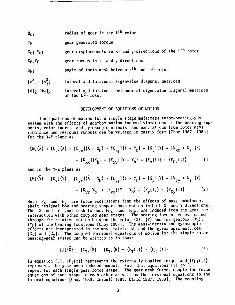
DEVELOPMENT OF EQUATIONS OF MOTION
The equations of motion for a single stage multimass rotor-bearing-gearsystem with the effects of gearbox motion induced vibrations at the bearing sup-ports, rotor inertia and gyroscopic effects, and excitations from rotor massimbalance and residual runouts can be written in matrix form [Choy 1987, 1989]
for the X-Y plane as
[M]{X} + [Gx](_( } + [Cxxl{X - Xb} + [Cxy]{_/ - _(b} + [Gyl{Y} + [Kxx + Ks]{X}
_ [Kxxl{Xb} + [Kx.yl{Y- yb} = {Fx(t)} + {FGx(t)} (1)
and in the Y-Z plane as
[M]{;_} - [Gx]{Y} + [Cyx]{X - Xb } + [Cy_y]{// - Yb } - [Gy]{Y} + [Kyy + Ks](Y}
- [gyy{Yb} + [Kyxl{Y- Yb} = {Fy(t)} + {FGy(t)} (2)
Here Fx and Fv are force excitations from the effects of mass imbalance,shaft residual bSw and bearing support base motion in both X- and Y-directions.The X and Y gear mesh forces, FGx and FGv. are induced from the gear teethinteraction with other coupled gear stages. The bearing forces are evaluatedthrough the relative motion between the rotor {X}, {Y} and the gearbox {Xb},
{Yb} at the bearing locations [Choy 1987]. The mass-inertia and gyroscopiceffects are incorporated in the mass matrix [M] and the gyroscopic matrices
[Gx] and [Gy]. The coupled torsional equations of motion for the single rotor-bearing-gear system can be written as follows:
[J](O) + [CT]{O} + [KT]{®) = {FT(t) } + {FGt(t)} (3)
In equation (3), {FT(t) } represents the externally applied torque and {FGt(t)}represents the gear mesh induced moment. Note that equations (1) to (3)repeat for each single gear/rotor stage. The gear mesh forces couple the forceequations of each stage to each other as well as the torsional equations to thelateral equations [Choy 1989, Cornell 1981, David 1987, 1988]. The coupling
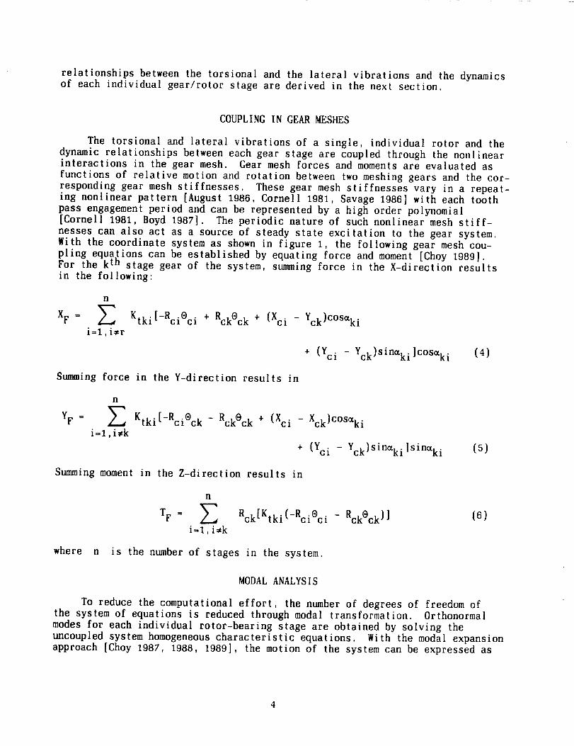
relationships between the torsional and the lateral vibrations and the dynamicsof each individual gear/rotor stage are derived in the next section.
COUPLING IN GEAR MESHES
The torsional and lateral vibrations of a single, individual rotor and the
dynamic relationships between each gear stage are coupled through the nonlinearinteractions in the gear mesh. Gear mesh forces and moments are evaluated as
functions of relative motion and rotation between two meshing gears and the cor-
responding gear mesh stiffnesses. These gear mesh stiffnesses vary in a repeat-ing nonlinear pattern [August 1986, Cornell 1981, Savage 1986] with each toothpass engagement period and can be represented by a high order polynomial[Cornell 1981, Boyd 1987]. The periodic nature of such nonlinear mesh stiff-
nesses can also act as a source of steady state excitation to the gear system.With the coordinate system as shown in figure 1, the following gear mesh cou-pling equations can be established by equating force and moment [Choy 1989]For the k th stage gear of the system, summing force in the X-direction resuitsin the following:
XF=
n
Ei=l,i,r
Ktki[-Rci®ci + RckOck + (Xci - Yck)COSaki
+ (Yci - Yck)Sinaki]C°Saki (4)
Summing force in the Y-direction results in
YF =
n
E Ktki[_RciOck - RckOck + (Xci - Xck)COS_ki
i=l,i,k
+ (Yci - gck)Sin_ki]sinaki (5)
Summing moment in the Z-direction results in
n
TF = _ Rck[Ktki(-Rci®ci
i=l,i,k
- Rck®ck)] (6)
where n is the number of stages in the system.
MODAL ANALYSIS
To reduce the computational effort, the number of degrees of freedom ofthe system of equations is reduced through modal transformation. Orthonormal
modes for each individual rotor-bearing stage are obtained by solving theuncoupled system homogeneous characteristic equations. With the modal expansionapproach [Choy 1987, 1988, 1989], the motion of the system can be expressed as

where m
modes can be expressed as
m
{X} = _ Ai{_i}
i=1
m
{Y} = E Bi{¢_i}
i=1
(7)
m
{O} = _ At i{t)ti}
i=1
(8)
is the number of modes used. The orthogonality conditions of the
(9)
[¢]T[K][_] = [A2I
[¢tlT[Kt][*t ] = [A_I
(IO)
[o]T[M][Ol = [otlT[j][* t] = [[l
(11)
(12)
With the modal expansion and the orthogonality conditions, the modal equationsof motion [Choy 1989] can be written as follows:
X-Z equation
{A) + [oIT[Gxl[O](A} , [olT[Cxxl[¢I(A} + [oIT[cxy][OI(B} + [¢]T[Gyl[O]{B}
+ [A21{a} + [,IT[KxyI[OI{B} = [olT{Fx(t) + FGx(t)} (13)
Y-Z equation
{B} - [,]t[Cx][a]{fi } + [*]T[Cyxl[Ol(A} + [*]T[cyTl[Ol{fi} - [¢)T[cy][Ol(a}
+ [A2]{B} + [_]T[Kyx][O]{h } = [o]T{Vy(t) + FGy(t)} (14)
O-equation
{it} + [_t]T[CT][_t]{At } + [A_]{At} = [_t]T{Ft(t) + FGt(t)} (15)
The gear mesh forces and moment can also be expressed in the modal form, forthe ktn stage, as follows:

m
j=l
m
[O]_{YF} = Z ¢kjl
j=l
n
Zi=1, i_k
Ktki[-RciOci - RckOck + (Xci - Xck}COS_ki
+ (Yci - Yck}Sinaki]C°Saki
n
Z Ktki[_RciOci - RckOck + (Xci - Xck)COSaki
i=l ,1-,k
+ (Yci - Yck)SinCki
{16}
(17)
T[¢']k{TF } = Okjl Rck[Ktk i{-Rcioci - RckOck)] (18)
• 1=1, l_k
where K is the stage number, j is the mode number, and l is the stationlocation of the gear mesh.
SOLUTION PROCEDURE
Rearrange the modal equations of motion developed in equations (13)to {15} into the following:
X-equation
{A} = -[¢,]T[Gx][O]{A} - [¢]T[Cxx ][o]{A} - [¢]T[Cxy ][¢]{13} - [¢]T[Gy][,]{B}
- [A2]{A} - [¢,]T[Kxy][C)]{B } + [¢]T{Fx{t ) + FGx(t)}
Y- equa t i on
{i]} = [¢,]T[Cx][¢,I{i}} _ [¢]T[Cyx][¢,]{,_} _ [¢,]Ticyy][,}]{l}} + [¢,]T[{;y][,t,]{B }
(19)
- [A2]{ B} - [*]T[Kyx][*]{A} + [¢]T{Vy(t} + FGy(t} } (20)
O-equation
]T{At } = -[¢T]T[CTI[Ot]{At } - [A_]{it}[¢ t + {Ft{t} + FGt(t) } {21)
h variable time stepping Newmark-Beta integration scheme evaluates the modal
velocity and displacement at each time interval. In turn, equations (7) to (9}transform the modal displacements into absolute relative displacements in fixedcoordinates. The gear mesh forces can be evaluated by the relative motion
between the gear teeth using the nonlinear stiffnesses developed for the gearmesh interaction. The effects of gearbox vibration can be calculated as nonlin-
ear bearing forces through the relative vibration between the gearbox and
6
the shaft at the bearing locations. Since the gearbox and the shaft both arevibrating independently, a separate transient integration schemeis requiredfor each system at every time step before the coupling of bearing forces.
DISCUSSION OF RESULTS
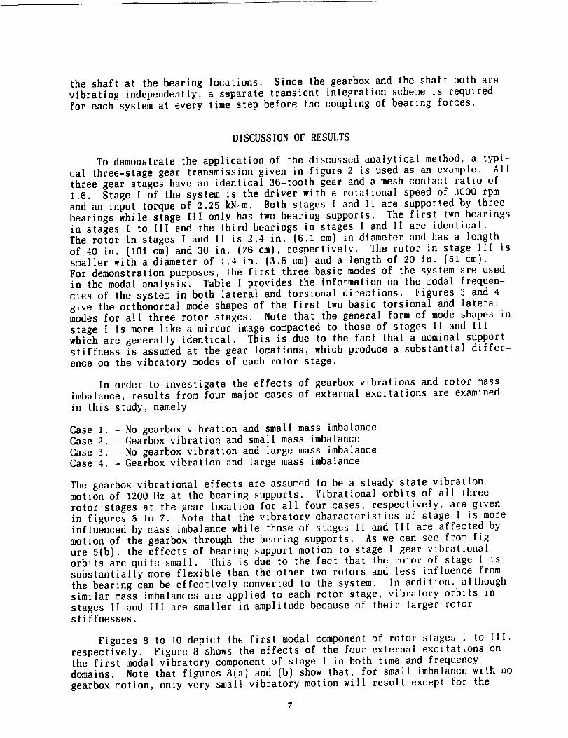
To demonstrate the application of the discussed analytical method, a typi-cal three-stage gear transmission given in figure 2 is used as an example. All
three gear stages have an identical 36-tooth gear and a mesh contact ratio of1.6. Stage I of the system is the driver with a rotational speed of 3000 rpmand an input torque of 2.25 kN-m. Both stages I and II are supported by three
bearings while stage III only has two bearing supports. The first two bearingsin stages I to [II and the third bearings in stages I and II are identical.The rotor in stages I and II is 2.4 in. (6.1 cm) in diameter and has a lengthof 40 in. (101 cm) and 30 in. (76 cm), respectively. The rotor in stage III issmaller with a diameter of 1.4 in. (3.5 cm) and a length of 20 in. (51 cm).
For demonstration purposes, the first three basic modes of the system are usedin the modal analysis. Table I provides the information on the modal frequen-cies of the system in both lateral and torsional directions. Figures 3 and 4
give the orthonormal mode shapes of the first two basic torsional and lateralmodes for all three rotor stages. Note that the general form of mode shapes in
stage I is more like a mirror image compacted to those of stages II and IlIwhich are generally identical. This is due to the fact that a nominal supportstiffness is assumed at the gear locations, which produce a substantial differ-
ence on the vibratory modes of each rotor stage.
In order to investigate the effects of gearbox vibrations and rotor massimbalance, results from four major cases of external excitations are examined
in this study, namely
Case 1. - No gearbox vibration and small mass imbalanceCase 2. - Gearbox vibration and small mass imbalance
Case 3. - No gearbox vibration and large mass imbalanceCase 4. - Gearbox vibration and large mass imbalance
The gearbox vibrational effects are assumed to be a steady state vibrationmotion of 1200 Hz at the bearing supports. Vibrational orbits of all three
rotor stages at the gear location for all four cases, respectively, are given
in figures 5 to 7. Note that the vibratory characteristics of stage I is moreinfluenced by mass imbalance while those of stages II and III are affected bymotion of the gearbox through the bearing supports. As we can see from fig-ure 5(b), the effects of bearing support motion to stage I gear vibrationalorbits are quite small. This is due to the fact that the rotor of stage I issubstantially more flexible than the other two rotors and less influence fromthe bearing can be effectively converted to the system. In addition, althoughsimilar mass imbalances are applied to each rotor stage, vibratory orbits in
stages II and III are smaller in amplitude because of their larger rotorstiffnesses.
Figures 8 to 10 depict the first modal component of rotor stages I to [II,respectively. Figure 8 shows the effects of the four external excitations onthe first modal vibratory component of stage [ in both time and frequencydomains. Note that figures 8(a) and (b) show that, for small imbalance with nogearbox motion, only very small vibratory motion will result except for the

dc component at zero frequency. Figures 8(c) and (d) represent the first mode
rotor vibrations resulting from gearbox motion. Note that the major componentoccurs at 1200 Hz (input vibratory frequency at the bearing supports) with a
minor component at 115 Hz (first natural frequency of stage I). Figures 8(e)and (f) show the effect of mass imbalance, which results in a large componentat the rotor speed of 50 Hz and a smaller component at the first mode of 115 Hz.
Figures 8(g) and (h) produce the combined effect of gearbox vibration andimbalance on rotor first mode vibrations. By examining the relative amplitudesof the major components, rotor speed, and gearbox vibration frequency, withtheir corresponding input excitation magnitude, the sensitivity of the rotor toimbalance and gearbox vibration can be determined. Similar conclusions can be
arrived in figures 9 and 10 for stages [I and III, except that the effects ofmass imbalance on first mode vibration is significantly reduced. As we can see
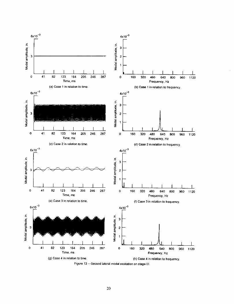
in figures 9(g) and (h) and lO(g) and (h), when both excitations are present,the gearbox motion has a much more dominating affect in rotor vibration forstages II and III as compared to stage I. Figures 11 to 13 show the vibration
of the second mode component for the three rotor stages, respectively. Note infigure 11, for stage I the second mode vibrational characteristics are very sim-ilar to those of the first mode. However, magnitudes of the second mode areapproximately 20 percent of those of the first mode. This is because the first
mode in the first stage is more easily excited by the imbalances and gear forcesacting at the gear location. Further examinations of figures 12 and 13 showthat the second mode is more excited than the first mode in the second andthird rotor stages. A more detailed study of figures 3 and 4 reveals that the
second mode in stages II and llI is very similar to the shape of the first mode
in stage I, which is the first fundamental bending mode of the overhung rotorsystem. In addition, from figures 8 to 13, it was found that none of the tor-sional vibratory frequencies and gear meshing frequencies are excited in thelateral rotor vibration of the system.
Figure 14 depicts the gear mesh forces with effects of both imbalance andgearbox motion excitations. Note that the major component of these forces is
the dc component at zero frequency which is due to the constant applied torque.The other sizable force component is at the tooth meshing frequency of 1800 Hz.The higher ac component which results in higher meshing frequency componentbetween gears I and III, is because of the lower rotational stiffness in the
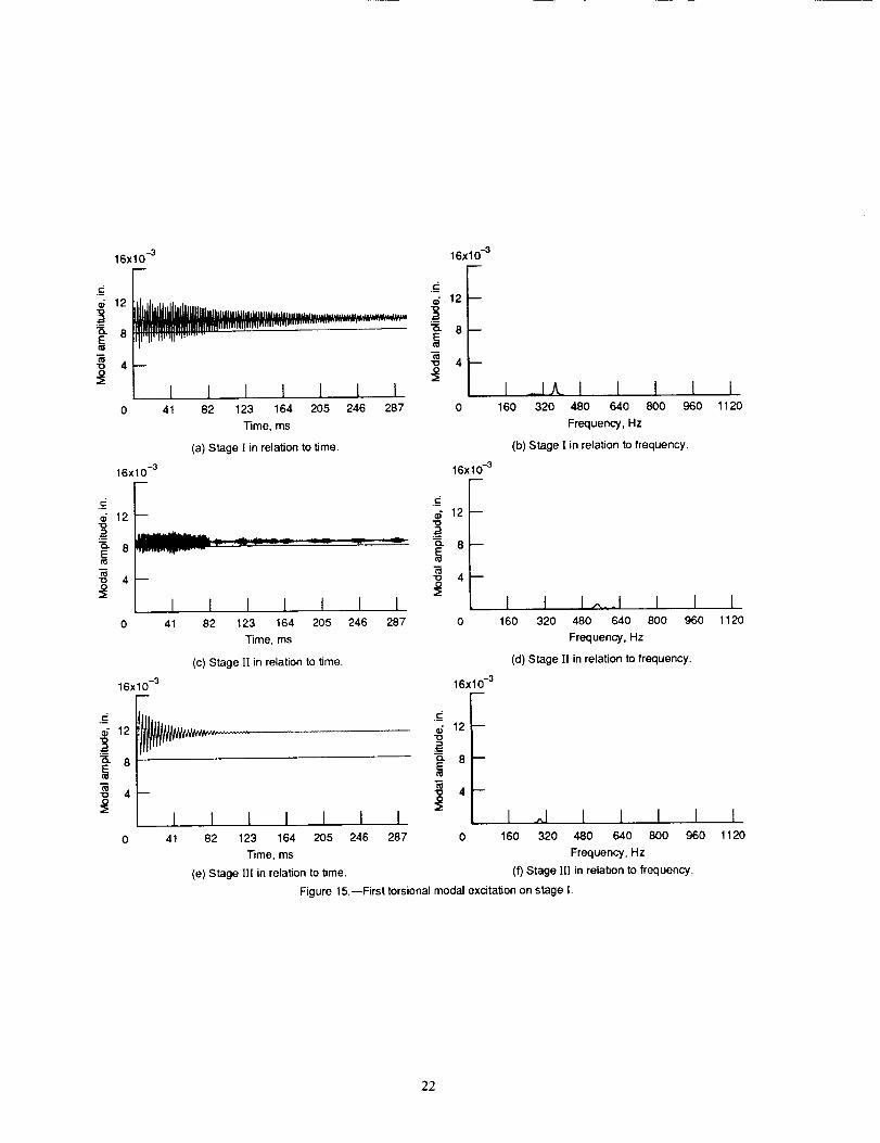
stage Ill rotor. This can also be observed by the higher dc (zero frequencycomponent) in stage [II compared to stage II, as shown in figures 15 and 16.Only a very small force component can be observed at the gear mesh frequency(1800 Hz) and first mode frequencies of stage I (355 Hz), stage II (550 Hz),and stage IIl (280 Hz). Again figures 15 and 16 outline the modal rotational
vibration characteristics of all rotor stages with both excitations. Note infigure 15 that other than the zero frequency component, the other sizable vibra-
tion is at its own rotational modal frequency (i.e., 355 Hz at stage I, 550 Hzat stage II, and 280 Hz at stage lII). Figure 16 depicts the second moderotational vibration characteristics. Note that similar conclusions can be
reached for the second modal frequencies of 1090, 1610, and 820 Hz, respec-tively, for stages I to lII.
SUMMARY OF RESULTS
This paper presents a vibration analysis with the effects of gearbox
motion and mass imbalance for multistage gear transmission. The analysis

combines gear mesh dynamics and structural modal analysis to study the trans-mission vibrations. The major content of this work can be summarized asfollows:
1. A comprehensive approach is developed to combine the nonlinear gearmesh dynamics with structural, lateral, and torsional vibration of the systemto determine the global system response.
2. The modal method transforms the equations of motion into modal coordi-nates to reduce the degrees of freedom of the system of equations.
3. Gear force observations in both the time and frequency domains provide
good insights into the source of dominating response forces.
4. The magnitude of the gear mesh force is inversely proportional to therotor stiffness of the geared system.
5. The influence of the gearbox motion to system vibration is more pro-nounced in a stiffer rotor system.
6. Gear tooth mesh frequency and torsional modal frequencies have substan-tial effects on rotational but not on lateral vibrations of the system.
7. Knowledge of modal amplifications under various excitations providean understanding of the vibrational characteristics of the system. This knowl-edge is crucial for designing transmissions with improved performance anddurability.
REFERENCES
August, R.; and Kasuba, R., "Torsional Vibrations and Dynamic Loads in a BasicPlanetary Gear System," Journal of Vibration, Acoustics, Stress, and
Reliability in Design, Vol. 108, No. 3, pp. 348-353, 1986.
Boyd, L.S.; and Pike, J.A., "Epicyclic Gear Dynamics," AIAA Paper 87-2042,June 1987. Presented at the AIAA/SAE/ASME/ASEE 23rd Joint propulsionConference, San Diego, CA, 1987.
Choy, F.K.; and Li, W., "Frequency Component and Modal Synthesis Analysis of
Large Rotor/Bearing Systems with Base Motion Induced Excitations," Journal ofFranklin Institute, Vol. 323, No. 2, pp. 145-168, 1987.
Choy, F.K.; Padovan, J.; and Li, W., "Rub in High Performance Turbomachinery:Modelling; Solution Methodology; and Signature Analysis," Mechanical Systems
and Signal Processing, Vol. 2, No. 2, pp. 113-133, 1988.
Choy, F.K.; Townsend, D.P.; and Oswald, F.B., "Dynamic Analysis ofMultimesh-Gear Helicopter Transmissions," NASA TP-2789, 1988.
Choy, F.K.; Tu, Y.K.; Savage, M.; and Townsend, D.P., "Vibration SignatureAnalysis of Multistage Gear Transmission," NASA TM-101442, 1989. Presented atthe ASME Fifth International Power Transmission and Gearing Conference,
Chicago, Illinois, April 1989.
9

Cornell, R.W., "Compliance and Stress Sensitivity of Spur Gear Teeth," Journalof Mechanical Design, Vol. 103, No. 2, pp. 447-459, 1981.
David, J.W.; and Park, N., "The Vibration Problem In Gear Coupled RotorSystems," in Rotating Machinery Dynamics; llth ASME Vibrations and Noise
Conference, Boston, m r Sept. 29, 1987, A. Muszynska and J.C. Simonis, eds.,Vol. 2, 1987, pp. 297-304, ASME, New York, 1987.
David, J.W.; Mitchell, L.D.; and Daws, J.W., "Using Transfer Matrices forParametric System Forced Response," Journal of Vibration, Acoustics, Stress,and Reliability in Design, Vol. 110, No. 3, pp. 263-269, 1988.
Lin, H.; Huston, R.L.; and Coy, l.J., "On Dynamic Loads in Parallel Shaft
Transmissions: Part I - Modelling and Analysis," Journal of Mechanisms,Transmissions and Automation in Design, Vol. 110, No. 2, pp. 221-225, 1988.
Mitchell, L.D.; and David, J.W., "Proposed Solution Methodology for theDynamically Coupled Nonlinear Geared Rotor Mechanics Equations," Journal ofVibration, Stress, and Reliability in Design, Vol. 107, No. 1,pp. 112-116, 1985.
Savage, M.; Caldwell, R.J.; Wisor, J.W.; and Lewicki, D.G., "Gear Mesh
Compliance Modelling," NASA I31-88843, 1986. Presented at the Rotary WingPropulsion System Specialist's Meeting of the American Helicopter Society,Williamsburg, VA, Nov. 12, 1986.
TABLE I. - SYSTEM NATURAL FREQUENCIES
Mode I Stage I Stage II Stage III
Torsional natural frequencies, Hz
1 355 550 2802 1090 1610 820
Lateral natural frequencies, Hz
1 115 160 1102 145 189 200
2 190 264 160
10

ith stage
i
Y
kth stage ,_X
/z
Figure 1 .--Coordinate system for gear mesh force.
Bearing
supports/ \
/ I \
/ I \
S U S
Stage I
Figure 2.--Three-stage
m
m
Stage Ill
rotor-bearing gear system.
[-] nN M _]1U U U
Stage II
-1
Mode
First lateral
First torsional
Bearing Bearing Bearing
(a) Stage I.
1
(b) Stage [I.
0
-1(c) Stage III.
Figure 3.--First vibration mode of three-
stage system.
Mode
Second lateralSecond torsional
1 Bearing Bearing Bearing
°i i /-11-- i
(a) Stage I.
-1
(b) Stage II.
1i-0
/ \\_I t" I-1
(c) Stage 111.
Figure 4.--Second vibration mode of three-
stage system.
11

.09 --
.O6
.03
-.03
-.06
._d-.09c"
_, .O9 --
.06 --
.03 --
0 --
-.03 --
--,0_ --
--.09
I(a) Case 1.
I I I
I I I I-.06 -.03 0 .03
(b) Case 2.
I I.06 .09 -.09
x-direction, in.
I I I(c) Case 3.
I I I I I I-.06 -.03 0 .03 .06 .og
Figure 5.--Stage I rotor vibrational orbit.
(d) Case 4.
12

,09 m
.06 --
.03 --
0 --
-.03
-.06
d -.09 I¢-0
"? .09 --
.06 --
.03 --
0
-.03 --
-,06 --
-.09 I-.09 -.06
I I I I(a) Case 1.
I I I I-.03 0 .03 .06
(b) Case 2.
m
I
I I I.09 -.09 -.06 -.03
x-direction, in.
Figure 6._tage II rotor vibrational orbit.
I I I I I I(c) Case 3.
I0
(d) Case 4.
I.03
[.06
I.09
13

.ogm
.06 --
.03 --
0
-.03
-.06
c -.09
c-o
.b.
"9, .og
.06 --
.03 --
0 --
-.03
-.06 --
-.09
-.Og
I I I I I I(a) Case 1.
I t I I-.06 -.03 0 .03
(b) Case 2.
B
E
B
I I I.06 .og -.09 -.06
x-direction, in.
Figure 7.--Stage If! rotor vibrational orbit.
I I t I I I(c) Case 3.
I I I I I-.03 0 .03 .06 .og
(d) Case 4.
14

4x10 -2
N3--
_2E
_1--
O 41
4x10 -2
.__
_- 310
_2
-o 1
I I I I I I82 123 164 205 246 287
Time, ms
(a) Case 1 in relation to time.
I I I I I I I I41 82 123 164 205 246 287
Time, ms
(c) Case 2 in relation to time.
4x10 -2
c
_" 3"10
_2
m
AAAAAAA WVVVVV',
I I I I I I 141 82 123 164 205 246 287
Time, ms
(e) Case 3 in relation to time.
4x10 -2
t-
N 3"O
_2
I I I I I 1 I41 82 123 164 205 246 287
Time, ms
(g) Case 4 in relation to time.
12x10 -3
E;
"O
o. 6 --E
12x10 -3
9--"1o
_-6--
T8 3--
_1 I I I I I I160 320 480 640 800 960 1120
Frequency, Hz
(b) Case 1 in relation to frequency•
|41 I l_J I I I
160 320 480 640 800 g60 1120
Frequency, Hz
(d) Case 2 in relation to frequency.
12x10 -3
.c__ 9
"O
.a
-o 3
0
12x10 -3
t--:
,_ 9"0
__=
?=3
I I I I I I160 320 480 640 800 960 1120
Frequency, Hz
(f) Case 3 in relation to frequency.
|_,,_1 I I JLL_ I I I
160 320 480 640 800 960 1120
Frequency, Hz
(h) Case 4 in relation to frequency.
Figure 8.--First lateral modal excitation on stage I.
15

8x10 _
.i
_6--
8x10 _
41
I 1 I I I I82 123 164 205 246 287
Time, ms
(a) Case 1 in relation to time.
t-.
6"O
_4
?=2
0 41
8x10 -4
_" 6 --"10
_4
8x10 -4
I 1 I I I I82 123 164 205 246 287
Time, ms
(c) Case 2 in relation to time.
_"-. J"_-.,,.j_.,.._/_,_j ,'_., P_,. v.. ''_. _._ ,P_,
I I I I I I t41 82 123 164 205 246 287
Time, ms
(e) Case 3 in relation to time.
c
_" 6
q
_4
"_ 2
41
I I I I I I82 123 164 205 246 287
Time, ms
(g) Case 4 in relation to time,
4x10 -3
¢.-
_- 3 --"o
_-2-
0
4x10 -3
E:
_-2--r0
4x10 -3
c
_" 3 --
Q" 2 --E1'0
0
4x10 -3
3 --
_-2--
o l
I 1_ I t I t I160 320 480 640 800 960 1120
Frequency, Hz
(b) Case 1 in relation to frequency.
I I t_ I I I160 320 480 640 800 960 1120
Frequency, Hz
(d) Case 2 in relation to frequency•
I I. I I I I I160 320 480 640 800 960 1120
Frequency, Hz
(f) Case 3 in relation to frequency.
I I I_q. I I I160 320 480 640 800 960 1120
Frequency, Hz
(h) Case 4 in relation to frequency•
Figure 9.--First lateral modal excitation on stage [].
16

2x10 -3
t-,w
,"-i 1 Lh_" -v "-h" -"E
"1oO
I0 41
c
"O
m
I I I I I [82 123 164 205 246 287
Time, ms
(a) Case linrelationtotime.
2x10 -3
2x10 -3
E
O
2x10 -3
"10
_f(_
'10O
I I I I I I I41 82 123 164 205 246 287
Time, ms
(c) Case 2 in relation to time.
/vVVVv.vvvvvvvv -w_ -v_ -.,v-
I I I I I I I41 82 123 164 205 246 287
Time, ms
(e) Case 3 in relation to time.
I I I I I I I41 82 123 164 205 246 287
Time, ms
(g) Case 4 in relation to time.
2x10 -3
_I--E
2x10 -3
E
6"10
_-1--
"O
_1 I I I I I I160 320 480 640 800 960 1120
Frequency, Hz
(b) Case 1 in relation to frequency.
.I I I_._ I I I
160 320 480 640 800 960 11 20
Frequency, Hz
(d) Case 2 in relation to frequency•
2x10 -3
"O
o. 1 --E
"E3
,.I
2x10 -3
=-"10
_-1--
"10
I I I I I I160 320 480 640 800 960 1120
Frequency, Hz
(f) Case 3 in relation to frequency.
• ^1 I I_l I I I
160 320 480 640 800 960 1120
Frequency, Hz
(h) Case 4 in relation to frequency.
Figure lO.--First lateral modal excitation on stage HI.
17

4x10 -3
c
4x10 -3
d 3"0
_- 2E
1
4x10 -3
r-
d 3
E
-a 1
I41
t I ] I I I82 123 164 205 246 287
Time, ms
(a) Case 1 in relation to time.
41
I I I I I I82 123 164 205 246 287
Time, ms
(c) Case 2 in relation to time.
24x10-4
c
d 18"1oE}
_- 12 --
•_ 6 --
AAAAAAA/k/VVVV/
I I [ [ I I I41 82 123 164 205 246 287
Time, ms
(e) Case 3 in relation to time.
_1 I I I I I I160 320 480 640 800 960 1120
Frequency, Hz
(b) Case 1 in relation to frequency•
24x 10-4
¢:
d 18 --"0
1,,I I I _ I I I
160 320 480 640 800 960 1120
Frequency, Hz
(d) Case 2 in relation to frequency.
24x 10 -4
d 18"0
0 0
_1 I I I I I t160 320 480 640 800 960 1120
Frequency, Hz
(f) Case 3 in relation to frequency.
4x10 -3 24x10 -4
oF vvvvv,AAAAAA _'18
_- 2 1 _-12
I I I I I I :_ 1|
I I JLL I I I41 82 123 164 205 246 287 0 160 320 480 640 800 960 1120
Time, ms Frequency, Hz
(g) Case 4 in relation to time. (h) Case 4 in relation to frequency•
Figure 11 .--Second lateral modal excitation on stage [.
18

8x10 -3
_6--
_4E
8x10 -3
_" 6
_4
"o 2
I I I I 1 I 141 82 123 164 205 246 287
Time, ms
(a) Case 1 in relation to time.
8x10 -3
_" 6
Q- 4E
-o 2O
I I I I I I I41 82 123 164 205 246 287
Time, ms
(c) Case 2 in relation to time.
i
8x10 -3
I41
I I I I 1 I82 123 164 205 246 287
Time, ms
(e) Case 3 in relation to time.
¢z
_" 6"10
m
_4o_
2
I41
I I I I 1 I82 123 164 205 246 287
Time, ms
(g) Case 4 in relation to time.
4x10 -3
_- 3 --
.__=_- 2 --E
-_ 1 --
4X10 -3
¢.,-
_" 3--"0
_-2--
[0
4x10 -3
"O
_-2-
°I 1-0
4x10 -3
_- 3"10
_2
I I. I I I I I160 320 480 640 800 960 1120
Frequency, Hz
(b) Case 1 in relation to frequency.
I I 1___ _..._ I I I160 320 480 640 800 960 1120
Frequency, Hz
(d) Case 2 in relation to frequency.
I I_ I I I I I160 320 480 640 800 960 1120
Frequency, Hz
(f) Case 3 in relation to frequency.
p
t i IJ_J i I I160 320 480 640 800 960 1120
Frequency, Hz
(h) Case 4 in relation to frequency.
Figure 12.--Second lateral modal excitation on stage ][.
]9
6X10 -3
c
d"0
I I I I I I82 123 164 205 246 287
Time, ms
(a) Case 1 in relation to time.
6x10 -3
41
d"0
_3
"o
t.-
d"10
_3
'qO
I I I I I I I0 41 82 123 164 205 246 287
Time, ms
(c) Case 2 in relation to time.
6x10 -3
6x10 -3
I41
I I I I I I82 123 164 205 246 287
Time, ms
(e) Case 3 in relation to time.
d
"10
41
I I I I I I82 123 164 205 246 287
Time, ms
(g) Case 4 in relation to time.
4x10 -3
c
d3--
_2-m
I
0
4x10 -3
d
d 3 --"10
m
!
0
-34xl
d 3 --"10
-_=_- 2 --EcO
-R"1o 1 --
4x10 -3
t-
d 3_
_-2--
0
I I I I I I I160 320 480 640 800 960 1120
Frequency, Hz
(b) Case 1 in relation to frequency.
I I l_J _J__ I I I160 320 480 640 800 960 1120
Frequency, Hz
(d) Case 2 in relation to frequency.
I I 1 I I I I160 320 480 640 800 960 1120
Frequency, Hz
(f) Case 3 in relation to frequency.
AI I I_J_ I I I
160 320 480 640 800 960 1120
Frequency, Hz
(h) Case 4 in relation to frequency.
Figure 13.--Second lateral modal excitation on stage II].
2O

32x102
16
c_ 0"6
_ -16ii
-320
I 1 I I I I I41 82 123 164 205 246 287
Time, ms
(a) Force of gears 1 and 2 in relation to time.
OLL
240x102
180 --
120 --
60 B
20 40 60 80 100 120 140
Frequency, Hz
(b) Force of gears 1 and 2 in relation to frequency.
32x102
_ 0
0
EL
-32V I I I I I I I0 41 82 123 164 205 246 287
Time, ms
(c) Force of gears 1 and 3 in relation to time.
240x102
180 --d
120 --
/
I^ ^1 _,L [ _ I 1 L
20 40 60 80 100 120 140
Frequency, Hz
(d) Force of gears 1 and 3 in relation to frequency.
Figure 14.--Gear force in time and frequency domains.
21
16x10 -3 16x10 -3
12 [J_llJWIJHII.i,,,.,,,,,,.,,,,,.,,..,,.,...........................................12
_. _|Wnl_llfllllglnTlpllllmlqm,fvm'l""! ................ "................
.Tll,ql,,lt....... _"88
_4 +4:_ |1 I I I I I I [ _1_.1 I
0 41 82 123 164 205 246 287 0 160 320 480 640
Time, ms Frequency, Hz
(b) Stage [ in relation to frequency.(a) Stage ! in relation to time.
,pk.m.lm_,_p,_,-. ,--r -¸ -_Y T .....
16x10 -3
c
12 --
E
I I I800 960 1120
I I I I I I I 1 I I ,,_+.1 I I [41 82 123 164 205 246 287 0 160 320 480 640 800 960 1120
Time, ms Frequency, Hz
(c) Stage ][ in relation to time. (d) Stage ]! in relation to frequency.
16x10 -3
12
_- 8E
4 --
I
16x10 -3
12
_ 8
16x10 -3
12--
_- 8
I I I I I I 1 , I At I I I I41 82 123 164 205 246 287 0 160 320 480 640 800 960
Time, ms Frequency, Hz
(e) Stage Ill in relation to time. (f) Stage [[I in relation to frequency.
I1120
Figure 15.--First torsional modal excitation on stage L
22

4X10 -3
c
_2
4x10 -3
¢" 3--"0
__=_- 2E
-o I --
if2
a; 3"0
_2
o 1
I I I I I I I41 82 123 164 205 246 287
Time, ms
(a) Stage ] in relation to time.
_='". ,.L__ .. ",',',,,
4x10 -3
F
41
t I I I I I82 123 164 205 246 287
Time, ms
(c) Stage I[ in relation to time.
0 41
I I I I I I82 123 164 205 246 287
Time, ms
(e) Stage ][! in relation to time.
2x10 -3
c
d"o
o. 1 --E
I I I I xl I I I0 225 450 675 900 1125 1350 1575 1800
Frequency, Hz
(b) Stage ! in relation to frequency.
2x10 -3
¢.-
d
o_ 1 --E
"0
2x10 -3
d
e-_ 1 --E
"o
I I I I I I L I225 450 675 900 1125 1350 1575 1800
Frequency, Hz
(d) Stage ][ in relation to frequency.
/I _I I _J_ I 1 I I
225 450 675 900 1125 1350 1575 1800
Frequency, Hz
(f) Stage IH in relation to frequency.
Figure 16.--Second torsional modal excitation on stage [.
23

Nallonal Aeronauhcs and
Space Adm_nistratEon
1. ReportNo. NASA TM-103109 2. GovernmentAccession No.
AVSCOM TR_C-0224. Title and Subtitle
Dynamics of Multistage Gear Transmission With Effects of GearboxVibrations
Report Documentation Page
7. Author(s)
F.K. Choy, Y.K. Tu, J.J. Zakrajsek, and D.P. Townsend
9. PerformingOrganizationName and Address
NASA Lewis Research Center
Cleveland, Ohio 44135-3191and
Propulsion Directorate
U.S. Army Aviation Systems CommandCleveland, Ohio 44135-3191
3. Recipient's Catalog No.
5. ReportDate
6. PerformingOrganizationCode
8. PerformingOrganizationReport No.
E-5433
10. Work Unit No.
505-63-5A and 505-62-0K
! L 162209A47A
1. Contractor Grant No.
13. Type of Reportand Period Covered
Technical Memorandum
14. SponsoringAgencyCode
12. SponsoringAgency Name and Address
National Aeronautics and Space Administration
Washington, D.C. 20546-0001and
U.S. Army Aviation Systems CommandSt. Louis, Mo. 63120-1798
15. SupplementaryNotes
Prepared for the CSME Mechanical Engineering Forum 1990 sponsored by the Canadian Society of Mechanical
Engineers, Toronto, Canada, June 3-9, 1990, F.K. Choy and Y.K. Tu, Department of Mechanical Engineering,The University of Akron, Akron, Ohio 44325; J.J. Zakrajsek and D.P. Townsend, NASA Lewis ResearchCenter.
16. Abstract
This paper presents a comprehensive approach in analyzing the dynamic behavior of multistage gear transmission
systems with the effects of gearbox induced vibrations and mass imbalances of the rotor. The modal method, with
undamped frequencies and planar mode shapes, is used to reduce the degrees of freedom of the gear system for
time-transient dynamic analysis. Both the lateral and torsional vibration modes of each rotor-bearing-gear stage as
well as the interstage vibrational characteristics are coupled together through localized gear mesh tooth inter-
actions. In addition, gearbox vibrations are also coupled to the rotor-bearing-gear system dynamics through
bearing support forces between the rotor and the gearbox. Transient and steady state dynamics of lateral and
torsional vibrations of the geared system are examined in both time and frequency domains to develop inter-
pretations of the overall modal dynamic characteristics under various operating conditions. A typical three-stage
geared system is used as an example. Effects of mass imbalance and gearbox vibrations on the system dynamic
behavior are presented in terms of modal excitation functions for both lateral and torsional vibrations. Operationalcharacteristics and conclusions are drawn from the results presented.
17. Key Words (Suggestedby Author(s))
Gearbox
Vibration
Dynamics
Multistage
!18. DistributionStatement
Unclassified- Unlimited
Subject Category 37
19. SecurityClassif.(of this report) 20. SecurityClassif.(of this page) 21. No.of pages 22. Price*
Unclassified Unclassified 24 A03
NASAFORM1626OCT86 *For sale by the National Technical Information Service, Springfield, Virginia 22161