
Dynamical response of the Galileo Galilei on the ground ...
15
Dynamical response of the Galileo Galilei on the ground rotor to test the equivalence principle: Theory, simulation, and experiment. I. The normal modes G. L. Comandi Istituto Nazionale di Fisica Nucleare (INFN), Sezione di Pisa, Largo B. Pontecorvo 3, I-56127 Pisa, Italy and Department of Physics, University of Bologna, I-40I26 Bologna, Italy M. L. Chiofalo Scuola Normale Superiore, Piazza dei Cavalieri 7, I-56100 Pisa, Italy; Istituto Nazionale di Fisica Nucleare (INFN), Sezione di Pisa, Largo B. Pontecorvo 3, I-56127 Pisa, Italy R. Toncelli and D. Bramanti Istituto Nazionale di Fisica Nucleare (INFN), Sezione di Pisa, Largo B. Pontecorvo 3, I-56127 Pisa, Italy E. Polacco and A. M. Nobili Department of Physics “E. Fermi,” University of Pisa, Largo B. Pontecorvo 3, I-56127 Pisa, Italy and Istituto Nazionale di Fisica Nucleare (INFN), Sezione di Pisa, Largo B. Pontecorvo, I-56127 Pisa, Italy Received 5 January 2006; accepted 16 January 2006; published online 23 March 2006 Recent theoretical work suggests that violation of the equivalence principle might be revealed in a measurement of the fractional differential acceleration between two test bodies—of different compositions, falling in the gravitational field of a source mass—if the measurement is made to the level of 10 -13 or better. This being within the reach of ground based experiments gives them a new impetus. However, while slowly rotating torsion balances in ground laboratories are close to reaching this level, only an experiment performed in a low orbit around the Earth is likely to provide a much better accuracy. We report on the progress made with the “Galileo Galilei on the ground” GGG experiment, which aims to compete with torsion balances using an instrument design also capable of being converted into a much higher sensitivity space test. In the present and following articles Part I and Part II, we demonstrate that the dynamical response of the GGG differential accelerometer set into supercritical rotation—in particular, its normal modes Part I and rejection of common mode effects Part II—can be predicted by means of a simple but effective model that embodies all the relevant physics. Analytical solutions are obtained under special limits, which provide the theoretical understanding. A simulation environment is set up, obtaining a quantitative agreement with the available experimental data on the frequencies of the normal modes and on the whirling behavior. This is a needed and reliable tool for controlling and separating perturbative effects from the expected signal, as well as for planning the optimization of the apparatus. © 2006 American Institute of Physics. DOI: 10.1063/1.2173075 I. INTRODUCTION Experimental tests of the equivalence principle EP are of seminal relevance as probes of general relativity. The equivalence principle is tested by observing its consequence, namely, the universality of free fall, whereby in a gravita- tional field all bodies fall with the same acceleration regard- less of their mass and composition. They therefore require two masses of different compositions, falling in the field of another “source” mass and a readout system to detect their motions relative to one another. An EP violation would result in a differential displacement of the masses in the direction of the source mass, which cannot be explained on the basis of known, classical phenomena e.g., tidal effects. The landmark experiment by Eötvös et al. 1 has estab- lished that a torsion balance is most well suited for the ground tests of the EP, thanks to its inherently differential nature. With the test masses suspended on a torsion balance they improved previous pendulum experiments by almost four-orders of magnitude, showing no violation for larger than a few 10 -9 . 1 Several decades later, by exploiting the 24 h modulation of the signal in the gravitational field of the Sun, torsion balance tests have improved to 10 -11 Ref. 2 and then to 10 -12 . 3 More recently, systematic and very care- ful tests carried out by Su et al. 4 and Adelberger et al. 5 using rotating torsion balances have provided even more firm evi- dence that no violation occurs to the level of 10 -12 . The relevant theoretical question for equivalence prin- ciple tests is at which accuracy level a violation, if any, is to be expected? In an earlier work by Damour and Polyakov, based on string theory and the existence of the dilaton, 6 values at which a violation might be observed have been determined to be in the range 10 -18 10 -13 . Fischbach et al. 7 have derived a nonperturbative rigorous result, accord- ing to which a violation must occur at the level of 10 -17 , due to the coupling between gravity and processes of - ¯ exchange which should differently affect masses with REVIEW OF SCIENTIFIC INSTRUMENTS 77, 034501 2006 0034-6748/2006/773/034501/15/$23.00 © 2006 American Institute of Physics 77, 034501-1 Downloaded 15 May 2006 to 131.114.73.5. Redistribution subject to AIP license or copyright, see http://rsi.aip.org/rsi/copyright.jsp
Transcript of Dynamical response of the Galileo Galilei on the ground ...

REVIEW OF SCIENTIFIC INSTRUMENTS 77, 034501 �2006�
Dynamical response of the Galileo Galilei on the ground rotorto test the equivalence principle: Theory, simulation, and experiment.I. The normal modes
G. L. ComandiIstituto Nazionale di Fisica Nucleare (INFN), Sezione di Pisa, Largo B. Pontecorvo 3, I-56127 Pisa, Italy andDepartment of Physics, University of Bologna, I-40I26 Bologna, Italy
M. L. ChiofaloScuola Normale Superiore, Piazza dei Cavalieri 7, I-56100 Pisa, Italy; Istituto Nazionale di Fisica Nucleare(INFN), Sezione di Pisa, Largo B. Pontecorvo 3, I-56127 Pisa, Italy
R. Toncelli and D. BramantiIstituto Nazionale di Fisica Nucleare (INFN), Sezione di Pisa, Largo B. Pontecorvo 3, I-56127 Pisa, Italy
E. Polacco and A. M. NobiliDepartment of Physics “E. Fermi,” University of Pisa, Largo B. Pontecorvo 3, I-56127 Pisa, Italyand Istituto Nazionale di Fisica Nucleare (INFN), Sezione di Pisa, Largo B. Pontecorvo, I-56127 Pisa, Italy
�Received 5 January 2006; accepted 16 January 2006; published online 23 March 2006�
Recent theoretical work suggests that violation of the equivalence principle might be revealed in ameasurement of the fractional differential acceleration � between two test bodies—of differentcompositions, falling in the gravitational field of a source mass—if the measurement is made to thelevel of ��10−13 or better. This being within the reach of ground based experiments gives them anew impetus. However, while slowly rotating torsion balances in ground laboratories are close toreaching this level, only an experiment performed in a low orbit around the Earth is likely to providea much better accuracy. We report on the progress made with the “Galileo Galilei on the ground”�GGG� experiment, which aims to compete with torsion balances using an instrument design alsocapable of being converted into a much higher sensitivity space test. In the present and followingarticles �Part I and Part II�, we demonstrate that the dynamical response of the GGG differentialaccelerometer set into supercritical rotation—in particular, its normal modes �Part I� and rejection ofcommon mode effects �Part II�—can be predicted by means of a simple but effective model thatembodies all the relevant physics. Analytical solutions are obtained under special limits, whichprovide the theoretical understanding. A simulation environment is set up, obtaining a quantitativeagreement with the available experimental data on the frequencies of the normal modes and on thewhirling behavior. This is a needed and reliable tool for controlling and separating perturbativeeffects from the expected signal, as well as for planning the optimization of the apparatus. © 2006American Institute of Physics. �DOI: 10.1063/1.2173075�
I. INTRODUCTION
Experimental tests of the equivalence principle �EP� areof seminal relevance as probes of general relativity. Theequivalence principle is tested by observing its consequence,namely, the universality of free fall, whereby in a gravita-tional field all bodies fall with the same acceleration regard-less of their mass and composition. They therefore requiretwo masses of different compositions, falling in the field ofanother “source” mass and a readout system to detect theirmotions relative to one another. An EP violation would resultin a differential displacement of the masses in the directionof the source mass, which cannot be explained on the basisof known, classical phenomena �e.g., tidal effects�.
The landmark experiment by Eötvös et al.1 has estab-lished that a torsion balance is most well suited for theground tests of the EP, thanks to its inherently differentialnature. With the test masses suspended on a torsion balance
they improved previous pendulum experiments by almost0034-6748/2006/77�3�/034501/15/$23.00 77, 03450
Downloaded 15 May 2006 to 131.114.73.5. Redistribution subject to
four-orders of magnitude, showing no violation for � largerthan a few 10−9.1 Several decades later, by exploiting the24 h modulation of the signal in the gravitational field of theSun, torsion balance tests have improved to 10−11 �Ref. 2�and then to 10−12.3 More recently, systematic and very care-ful tests carried out by Su et al.4 and Adelberger et al.5 usingrotating torsion balances have provided even more firm evi-dence that no violation occurs to the level of 10−12.
The relevant theoretical question for equivalence prin-ciple tests is at which accuracy level a violation, if any, is tobe expected? In an earlier work by Damour and Polyakov,based on string theory and the existence of the dilaton,6 �values at which a violation might be observed have beendetermined to be in the range 10−18���10−13. Fischbachet al.7 have derived a nonperturbative rigorous result, accord-ing to which a violation must occur at the level of ��10−17, due to the coupling between gravity and processes
¯
of �-� exchange which should differently affect masses with© 2006 American Institute of Physics1-1
AIP license or copyright, see http://rsi.aip.org/rsi/copyright.jsp

034501-2 Comandi et al. Rev. Sci. Instrum. 77, 034501 �2006�
different nuclei. More recent work8 suggests, in a new theo-retical framework for the dilaton, that a violation might oc-cur already at the level of ��10−12−10−13, depending on thecomposition of the masses.
While an ��10−13, and perhaps smaller, should be ac-cessible with rotating torsion balance experiments on theground, a sensitivity as high as ��10−17 could be achievedonly by an experiment flying in a low Earth orbit, where thedriving acceleration is up to three orders of magnitude larger.Specific instruments have been designed to carry out such anexperiment in space: satellite test of the equivalence prin-ciple �STEP� microscope, and “Galileo Galilei” �GG�.9–12
They share two features: that the test masses are concentriccylinders and that rotation of the spacecraft provides signalmodulation at frequencies higher than the orbital one.
GG is peculiar in that it spins around the symmetry axisand is sensitive to the relative displacements in the planeperpendicular to it: the cylindrical symmetry of the wholesystem and rotation around the symmetry axis allow a pas-sive attitude stabilization of the spacecraft with no need of amotor after an initial spin up to the nominal frequency �typi-cally 2 Hz�. The planar �instead of linear� sensitivity of theinstrument is also a crucial feature for allowing us to rotate atsupercritical speeds, i.e., faster than the natural frequenciesof the system. Faster rotation means modulation of the signalat higher frequency and therefore a reduced 1/ f noise �for1 / f noise see, e.g., the website maintained by Li13�. GG dif-fers from the other proposed space experiments also in thatthe test masses are suspended mechanically. We find that inthe absence of weight, as it is the case in space, mechanicalsuspensions too can provide extremely weak coupling, withthe additional advantage to electrically ground the testmasses.
The GG design naturally allows us to build and test afull scale 1 g version of the apparatus: by suspending theinstrument on a rotating platform through its spin/symmetryaxis, the sensitive plane lies in the horizontal plane of thelaboratory where a component of an EP violation signalmight be detected, similarly to a torsion balance experiment.“Galileo Galilei on the ground”14,15 �GGG� is primarily aprototype for testing the main novel features of the experi-ment proposed for flight. It is also an EP experiment in itsown right aiming to compete with torsion balance tests.4,5 Inthis effort, motor noise, low-frequency terrain tilts,16 andtidal perturbations17 are the main issues to be addressed.
A full knowledge of the dynamical response of the GGGrotor is needed, especially in view of its condition of super-critical rotation and of its common mode rejection behavior.The theoretical understanding of the dynamical properties ofthe rotor, together with the construction of a full simulationfacility, would allow us to predict and interpret the collectedexperimental data; they also provide a virtual environmentfor planning the experiment and optimizing its performance.
With these motivations in mind, we demonstrate that asimple but very effective mathematical model can be set upto quantitatively describe the dynamical properties of theGGG rotor. In this article �Part I�, we determine the normalmodes in all regimes, from subcritical to supercritical rota-
tion, and address the issue of self-centering in the super-Downloaded 15 May 2006 to 131.114.73.5. Redistribution subject to
critical rotation. In the following article �Part II�, we providethe dependence of the common mode rejection ratio onvarious system parameters which govern the design of theinstrument.
The differential equations in the model are solved bymeans of a user-friendly simulation program and the numeri-cal solutions are tested against the data available from theexperiment. The physical content of the model is also dis-cussed by means of approximate analytical solutions, whichprovide useful physical insight.
This article is organized as follows: Sec. II describes themain features of the experimental apparatus, Sec. III presentsthe dynamical model of the system, referring to specific ap-pendixes for details, Sec. IV reports on the numerical methodthat we have implemented, and Sec. V gives the results ob-tained on the determination of the normal modes of the sys-tem, showing an excellent agreement between the theoreticalpredictions and experimental data. The details of the calcu-lations are contained in two appendixes, while the third oneis specifically devoted to the important concept of self-centering. Concluding remarks are discussed in Sec. VI.
II. THE GGG ROTOR: OVERVIEWOF THE EXPERIMENT
GGG is a rotating differential accelerometer operated ina vacuum chamber �see Fig. 1�. It is made of two concentrichollow test cylinders, 10 kg each, weakly coupled by meansof a vertical arm—a tube located along the axis of thecylinders—to form a vertical beam balance �from now on weshall always omit the term “hollow” when referring to thetest cylinders�. The coupling arm is suspended at its midpointfrom a rotating vertical shaft in the shape of a tube enclosingit �see Figs. 1 and 2, right hand side�. A total of three sus-pensions are needed �drawn in red in Fig. 1�: a central one�see Fig. 2, left hand side� to suspend the coupling arm fromthe rotating shaft and one for each test cylinder to suspendeach of them from the top and bottom ends of the verticalcoupling arm.
The suspensions are cardanic laminar suspensions manu-
factured in CuBe which are stiff in the axial direction Z,
against local gravity, and soft in the plane X-Y orthogonal tothe axis so that the geometry is naturally two dimensional,the horizontal plane being sensitive to differential accelera-tions acting between the test cylinders. In the normal opera-tion mode, the modulation of such a signal is provided bysetting the whole system in rotation around the vertical axisin the supercritical regime, namely, at frequencies �s largerthan the natural differential frequencies of the rotor, typically�s�1.5 Hz. The differential character of the instrument isstrengthened by two differential readout systems made offour capacitance plates �indicated as IP, internal plates, inFig. 1� located in between the test cylinders and which arepart of two capacitance bridges in two orthogonal directions
of the sensitive plane.AIP license or copyright, see http://rsi.aip.org/rsi/copyright.jsp
034501-3 Rotating accelerometer for EP tests. I. Rev. Sci. Instrum. 77, 034501 �2006�
A. Description of the mechanical structureof the apparatus
The GGG apparatus is schematically presented in Fig. 1,
where a section through the spin-symmetry axis Z is showninside the vacuum chamber C. At the top center of the frameis the motor M whose shaft is connected to the suspensiontube of the rotor ST �drawn in yellow� by means of an ap-propriate motor-rotor joint and turns in the vertical directioninside ball bearings, indicated by x symbols in the figure.From the suspension tube ST rotation is then transmitted to atube located inside it which constitutes the vertical beam ofthe balance �also referred to as the coupling arm, Fig. 2, righthand side�, the connection between the two being provided atthe midpoint of the arm by the central laminar cardanic sus-pension �see Fig. 2, left hand side�.
The coupling arm in its turn transmits rotation to both
the test cylinders, since they are suspended �by means of twoDownloaded 15 May 2006 to 131.114.73.5. Redistribution subject to
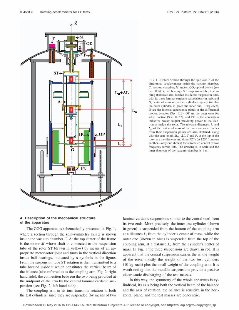
laminar cardanic suspensions similar to the central one� fromits two ends. More precisely, the inner test cylinder �shownin green� is suspended from the bottom of the coupling armat a distance Li from the cylinder’s center of mass, while theouter one �shown in blue� is suspended from the top of thecoupling arm, at a distance Lo from the cylinder’s center ofmass. In Fig. 1 the three suspensions are drawn in red. It isapparent that the central suspension carries the whole weightof the rotor, mostly the weight of the two test cylinders�10 kg each� plus the small weight of the coupling arm. It isworth noting that the metallic suspensions provide a passiveelectrostatic discharging of the test masses.
In this way, the symmetry of the whole apparatus is cy-lindrical, its axis being both the vertical beam of the balanceand the axis of rotation, the balance is sensitive in the hori-
FIG. 1. �Color� Section through the spin axis Z of thedifferential accelerometer inside the vacuum chamber.C, vacuum chamber; M, motor; OD, optical device �seeSec. II B�; x, ball bearings; ST, suspension tube; A, cou-pling �balance� arm, located inside the suspension tube,with its three laminar cardanic suspensions �in red�; andG, center of mass of the two cylinder’s system �in bluethe outer cylinder, in green the inner one, 10 kg each�.IP are the internal capacitance plates of the differentialmotion detector �Sec. II B�, OP are the outer ones forwhirl control �Sec. II C 2�, and PC is the contactlessinductive power coupler providing power to the elec-tronics inside the rotor. The relevant distances, Li andLo, of the centers of mass of the inner and outer bodiesfrom their suspension points are also sketched, alongwith the arm length 2La+�L. T and P, at the top of therotor, are the tiltmeter and three-PZTs �at 120° from oneanother—only one shown� for automated control of lowfrequency terrain tilts. The drawing is to scale and theinner diameter of the vacuum chamber is 1 m.
zontal plane, and the test masses are concentric.
AIP license or copyright, see http://rsi.aip.org/rsi/copyright.jsp

034501-4 Comandi et al. Rev. Sci. Instrum. 77, 034501 �2006�
B. The differential motion detector system
The differential motion detector �DMD� reflects the cy-lindrical symmetry of the system and is composed of thefollowing three parts.
�1� Two capacitance plates IP working as DMD�x� sensors�drawn as vertical lines in between the cylinders in Fig.1� are located halfway in between the test cylinders incorrespondence to the X direction with a clear gap of5 mm on either side and are connected to the suspensiontube by means of an insulating frame. A similar pair ofcapacitances forming a DMD�y� is placed in the Y di-rection. A voltage signal is applied to each capacitancebridge in order to shift the signal of interest to a high-frequency band with reduced 1/ f noise �with phaselocked detection�. The filtered signal is digitized by ananalog-to-digital converter �ADC� before transmissionto the nonrotating �laboratory� frame. Calibration andbalancing of the capacitance bridge are performed bymeans of the procedures outlined in Ref. 14. The bestsensitivity achieved in bench tests corresponds to me-chanical displacements of 5 pm in 1 s of integrationtime.11,14 Presently, the sensitivity of the readout systemduring normal operation is �10−9 m.
�2� An optical device OD located below the motor andabove the ball bearings, utilizing a disk with 32 holesand an infrared emitter-detector pair, provides a refer-ence signal for the angular position of the rotor. Thereference signal is combined with the X and Y channeldata from the DMD and encoded into RS232 format fortransmission to a computer. Then a second emitter-detector pair located at the very bottom of the rotor �us-ing a hole along the axis of the power coupler PC, seeFig. 1� transmits the digital signal from the rotor to thenonrotating frame from where it is taken out of the
FIG. 2. Left hand side: the central laminar cardanic suspension of the GGGrotor, located at the midpoint to the coupling arm in order to suspend it fromthe suspension tube �shaft�. Right hand side: the coupling arm inside thesuspension tube �shaft� as seen from the top. Two cardanic laminar suspen-sions are located at its top and bottom ends. They suspend the test cylinders�not shown here� through two metal rings. The dimensions of the ringsdepend on the dimensions of the concentric cylinders, which have equalmass �10 kg� and therefore different sizes. The top and bottom rings refer toouter and inner test cylinders, respectively.
vacuum chamber through electrical feedthroughs.
Downloaded 15 May 2006 to 131.114.73.5. Redistribution subject to
�3� An annular disk, in two semicircular parts, is mountedaround the upper half of the suspension tube and con-tains the two capacitance-bridge circuits and theirpreamplifiers �see Fig. 1�. The necessary electronics todemodulate the signal and convert it from an analog todigital form as well as the drivers for the optical emitterare also located here.
C. Principle of operation
For detecting an EP violation signal the instrument relieson its sensitivity to the relative displacement of the two testmasses, which in the final design will be made of differentmaterials. An acceleration in the horizontal plane of the labo-ratory acting differently between the test cylinders gives riseto a relative displacement of the two in the direction of theacceleration. This displacement unbalances the capacitancebridges and gives rise to an electric voltage proportional to it.
A modulation of the displacement, as seen by the capaci-tance plates, is achieved by setting the whole system in ro-tation around the vertical axis of symmetry passing throughthe shaft, as shown in Fig. 1. Note that the signal modulationobtained in this way does not affect the centers of mass ofthe test cylinders; hence, it does not affect their relative dis-placement, which is the physical quantity measured in theexperiment. As a result, this type of modulation reduces thenoise but not the signal.
In fact, this signal modulation could be achieved bykeeping the test cylinders stationary and rotating only thecapacitance plates �located in between the two, indicated asIP in Fig. 1� which form the differential motion detectorsystem described above. However, by rotating the test cylin-ders together with the capacitors, any irregularity in theirmass distribution averages out; moreover, the supercriticalregime can be exploited to reduce the rotation noise for allparts of the apparatus �see Sec. II C 2 and Appendix C�. Asfor the experiment in space, the rotation of the whole space-craft has two more very important advantages. In the firstplace, it eliminates the need for motor and ball bearings al-together, which are a considerable source of noise in theground experiment. Secondly, by rotating around the axis ofmaximum moment of inertia, the spacecraft is passively sta-bilized, thus reducing its weight, cost, and complexity, aswell as disturbances on the EP experiment.
An EP violation signal in the gravitational field of eitherthe Earth or the Sun would have a component in the hori-zontal plane of the laboratory which could be detected by theinstrument. Since the test bodies are rotors suspended on theEarth and the Earth rotates around its axis, this diurnal rota-tion gives rise to large gyroscopic effects on the test bodiesresulting in a nonzero differential acceleration which wouldmask an EP violation signal in the field of the Earth itself.The measurements of such gyroscopic effects have been re-ported in Ref. 14 �Sec. V, Fig. 12�. The instrument—in thisground based version—is therefore used for two purposes:�i� to establish its sensitivity as a prototype of the flight in-strument, namely, for an expected signal at the orbital fre-quency of the satellite ��1.75�10−4 Hz, i.e., about 1 1
2 h
period, at an Earth orbiting altitude of �520 km� and �ii� toAIP license or copyright, see http://rsi.aip.org/rsi/copyright.jsp

034501-5 Rotating accelerometer for EP tests. I. Rev. Sci. Instrum. 77, 034501 �2006�
look for an EP violation in the gravitational field of the Sun,in which case the signature of the signal �see Ref. 12, Sec. II�would have a dominant Fourier component of a 24 h perioddue to the diurnal rotation of the Earth.
1. Differential character and common mode rejectionThe differential character of the whole instrument,
namely, its capability to reject accelerations which are com-mon to both test masses, is in principle ensured by the ge-ometry and mounting of the test masses. It is further aug-mented by the differential nature of the DMD system.
�i� The sensitivity of the instrument to differential accel-erations of the test masses depends on the softness ofthe laminar suspensions and on the uniform distribu-tion of mass around the spin axis. Soft suspensionsand a good balancing of the rotor provide long naturalperiods for differential oscillations of the test massesrelative to each other, giving rise to larger relativedisplacements between the two and, in turn, to stron-ger output voltage signals.
The tuning of the natural differential period TD ofthe test cylinders is made possible by changing a mo-ment arm in the beam balance. This is accomplishedby moving a small solid ring mounted at the lowerend of the balance �coupling� arm. Moving this ring
vertically along the arm, in the Z direction, displacesthe center of mass of the balance arm from its suspen-sion point by a quantity �L. If �L=0 the center ofmass of the balance arm is coincident with its suspen-sion point. �L can be adjusted to be either slightlypositive or negative, resulting in a longer or shorterTD. However, there is a maximum positive value that�L can assume before the system becomes unstable�see Eq. �39� below�.
Asymmetric distribution of mass of the rotor in thehorizontal plane, resulting in a nonzero inclination ofthe coupling arm in the rotating reference frame, mayalso be corrected by two small masses mounted insidethe coupling arm itself, one of which is movable inthe X direction and the other in the Y.
The tilt of the spin axis with respect to the nonro-tating laboratory frame is controlled by 3 �m screwswhich support the plate on which the rotor shaft ismounted. In addition the tilt can be finely adjustedusing piezoelectric actuators �P� attached to the tipsof the micrometer screws �see Fig. 1�.
�ii� As to the DMD system, a nonzero off centering of thecapacitor plates IP located in between the testcylinders—measured by the ratio �a−b� /a where a�b�is the nominal gap between the inner �outer� mass andany one of the capacitance plates—would make acommon mode displacement �xC of the test masses toproduce a differential output signal in addition to thatproduced by a real differential displacement �xD. Thelarger this off centering, the larger the fraction of thecommon mode displacement which is turned into a“fake” differential signal, i.e., which contributes to the
11
total unbalance �C of the capacitance bridge �GGDownloaded 15 May 2006 to 131.114.73.5. Redistribution subject to
Phase A Report, Sec. 2.1.3� from the original capaci-tance value Co,
�C
2C0�
a − b
a2 �xC −1
a�xD. �1�
2. Signal modulation and whirl motionsSignal modulation in testing the equivalence principle
has been first proposed in Ref. 2 in order to improve theexperiments of Eötvös et al.. By referring to the Sun ratherthan the Earth as the source mass of the gravitational field,the diurnal rotation of the Earth itself on which the testmasses are suspended provides a 24 h modulation with noneed to rotate the experimental apparatus, an operationwhich gives rise to relevant disturbances in such small forceexperiments. However, higher modulation frequencies aredesirable in order to reduce the 1/ f noise and, in fact, excel-lent results have been obtained by Refs. 4 and 5 with torsionbalances placed on a turntable rotating faster than the Earth.In GGG we try to spin the test masses much faster, at fre-quencies �typically a few hertz� higher than the natural fre-quencies �n of the system, a condition known as supercriticalrotation.
The GGG apparatus has three natural frequencies. Thedifferential frequency �D of the oscillations of the test bodiesrelative to one another and two common mode frequencies,�C1 and �C2, of both test masses together. In the GGG settingreported here their values are �D=0.09 Hz, �C1
=0.91 Hz,and �C2
=1.26 Hz.It is well known18–20 that in supercritical rotation the
masses are able to self-center and greatly reduce the originaloffsets of their centers of mass with respect to their ownrotation axes. Any initial offset, which inevitably resultsfrom construction and mounting errors, is, in fact, reducedby a factor ��D /�s�2. Such self-centering is a very essentialrequirement when using fast rotating macroscopic test bodiesfor the purpose of detecting the effects of extremely smallforces between them.
It is also well known that in supercritical rotation, dissi-pation in the system gives rise to destabilizing whirl motionsat frequencies �w equal �or close� to the natural frequenciesof the system, whose amplitude increases with time at a rate1 /�w=�w /Q��s� scaling as the whirl frequency �w and theinverse of the quality factor Q at the spin frequency �s.
20–22
Whirls can be stabilized by passive and active methods.Passive stabilization is typically used in engineering applica-tions of supercritical rotors, but it produces too large distur-bances for our purposes. We have used a passive damper inthe past only to stabilize the rotor during resonance crossing�see Ref. 14, Sec. III�. With the current improved apparatus,damping at resonance crossing is no longer needed. A muchfiner whirl stabilization can be performed actively by meansof eight small capacitance sensors/actuators �indicated as OP,outer plates, in Fig. 1� placed close to the outside surface ofthe outer test cylinder, four of them used as sensors and fouras actuators in two orthogonal directions of the horizontalplane.15 In the GGG experiment performed at supercritical
speed the relevant Q value is determined by losses due toAIP license or copyright, see http://rsi.aip.org/rsi/copyright.jsp

034501-6 Comandi et al. Rev. Sci. Instrum. 77, 034501 �2006�
deformations of the laminar suspensions at the spin fre-quency. Experimental measurements of Q are reported inRef. 14 and, more recently, in Ref. 23.
III. THE MODEL
Having described the real instrument, we are now in aposition to outline the minimal model used to describe itsdynamical behavior. Figure 3 displays a schematic represen-tation of the model in the reference frame �X�Y�Z�� rotatingwith the shaft at an angular velocity s=2�s around the Z�
axis ��s=sZ��. The relevant parts of the instrument de-picted in Fig. 1 are sketched in Fig. 3 with the same colors.The coupling arm, with mass ma �drawn in cyan as in Fig. 1�and length 2La+�L, is suspended at its midpoint MP fromthe rotating shaft and suspension tube ST �yellow� by meansof the central laminar suspension LS �red� with elastic con-stant K. The vector � is the offset of the arm center of massfrom the axis, which is unavoidable because of constructionand mounting errors. Variations of �L, as we have alreadydiscussed, produce a change of the mass distribution, henceof the natural differential period of the test masses, TD. Here,and with no loss of generality, � is placed along the X� axis.
The outer test cylinder, of mass mo �blue�, is suspendedfrom the top of the coupling arm by means of the laminarsuspension with elastic constant Ko and its center of mass isat a distance Lo from the suspension. In a similar manner, theinner test mass mi �green� is suspended from the bottom ofthe arm, Ki and Li being the corresponding parameters. Fromnow on, the label �= i ,o ,a will be used to refer to the pa-rameters of the inner mass, outer mass, and coupling arm,respectively. The three bodies have moments of inertia I��
= I��=m��3R�I2 +3R�E
2 +R�H2 � /12 and I� =m��R�I
2 +R�E2 � /2
along their principal axes ��, �, and �, R�I and R�E being theinternal and external radii of the cylinder �, and R�H itsheight.
The laminar suspensions have length l, the central one isslightly stiffer than the other two and we assume Ki=Ko
�K. In a refined version of the model, and whenever speci-fied, we also consider an anisotropic central suspension byintroducing the parameter � such that KY���KX�.
By defining the unit vector La of the coupling arm as
pointing from its midpoint towards the bottom suspension,Downloaded 15 May 2006 to 131.114.73.5. Redistribution subject to
and the unit vectors Lo and Li of the test cylinders eachpointing from the suspension to the center of mass of thebody �see Fig. 3�, the corresponding position vectors in therotating reference frame �X�Y�Z�� of Fig. 3 are
Ra = � − 0.5�LLa,
Ro = � − �La + �L�La + LoLo, �2�
Ri = � + LaLa + LiLi.
A. The Lagrangian
The Lagrangian L in the rotating reference frame�X�Y�Z�� can be written as
L = T − U , �3�
where the kinetic term can be very generally written as
T =1
2 �=a,o,i
��
��2dm�, �4�
after defining the velocity �� of the mass element dm� inbody � with volume ��. Then, U includes the potential ener-gies associated with gravity and with the elastic forces,namely,
U = Ug + Uel, �5�
where
Ug = �=a,o,i
− m�g · R� with g � − gZ�, �6�
Uel = �=o,i
1
2K�l2�Ra � R��2
+1
2La
2�KX��RaX˙��2
+ KY��RaY��2� . �7�
For the expression of Uel we refer to the small figure at thebottom right of Fig. 3, sketching the laminar suspension andits orientation.
We proceed along the main steps to derive the opera-
FIG. 3. �Color� Minimal model for the real instrumentsketched in Fig. 1 �see text for details�. On the left handside the various parts are drawn with the same colorsand labels as in Fig. 1. Here the midpoint of the cou-pling arm is indicated as MP. La, Lo, and Li refer to thedimensions of the coupling arm and the outer mass and
inner mass suspension arms, respectively. La, Lo, and Li
are the unit vectors of the corresponding beams. Theoffset vector �, due to construction and mounting im-perfections, is also indicated. On the right hand side wesketch one of the cylinders in the rotating referenceframe �X�Y�Z��, showing its principal axes of inertia�� ,� , �, the position vector R� ��=a ,o , i� of its centerof mass, and the angles �� ,��, which are not the usualEuler angles, as discussed in the text. Below this figure,the small one to the right shows a typical deformationof one of the laminar suspensions of length l, for in-stance, the central one. None of these figures is to scale.
tional expression for L. The bodies are rotating around their
AIP license or copyright, see http://rsi.aip.org/rsi/copyright.jsp

034501-7 Rotating accelerometer for EP tests. I. Rev. Sci. Instrum. 77, 034501 �2006�
own axis with angular velocity s in a reference frame whichis rotating as well, as sketched in Fig. 3, right hand side.Thus, we define as �� the angular-velocity vector of the
element dm� in the �X�Y�Z�� frame and �s=sZ�, so that
�� = V� + �� � r� = V� + �� � �R� + ��� , �8�
where V� is the velocity of the center of mass of body � andr� is the vector pointing to the element dm�, composed byR� and ��, as drawn in Fig. 3. By inserting Eq. �8� into Eq.�4�, we can write T as
T = Tkin + Tcor + Ucor + Uc, �9�
where the only nonzero terms are �see Appendix A for de-tails�
Tkin =1
2��m�V�
2 + �=�,�,
I�����2 , �10�
Tcor + Ucor = �
m�V� · ��s � R��
+ �
��
��� � ��� · ��s � ���dm�, �11�
Uc =1
2�
��
��s � �R� + ����2dm�. �12�
In Eq. �11� the terms coming from Coriolis forces havebeen split into the UCor potential energy, which contains onlythe position vectors, and TCor which contains also the veloci-ties. The centrifugal part Uc has been indicated as a potentialenergy. To proceed further, we now have to specify thechoice of the generalized coordinates.
B. Choice of the generalized coordinates
The GGG rotor model shown in Fig. 3 is composed ofnb=3 coupled bodies, for a total of 18 degrees of freedom.However, the central suspension prevents them from per-forming translational motions, thereby reducing the degreesof freedom to 9. In addition, the motor forces the three bod-ies to rotate at a constant angular velocity, so that the numberof degrees of freedom for the model is n=6.
We have chosen as generalized coordinates for eachbody the two angles �� and �� �see Fig. 3, right hand side�.These angles are defined slightly differently from the usual
Euler angles: �� is the angle between R� and the axis −Z�
and runs in the interval �0,�; �� is the angle from the X�axis to the projection of R� on the X�Y� plane and runs in theinterval �0,2�. We thus define the vector Q of the general-
ized coordinates and the corresponding velocities Q
Q = �q1,q2,q3,q4,q5,q6� = ��a,�a,�o,�o,�i,�i� . �13�
With these definitions in hand, we have that
La = �sin �a cos �a, sin �a sin �a,− cos �a� , �14�
and similar expressions for Lo and Li. Equation �14� turnsEqs. �2� into expressions for the R��Q� and the correspond-
ing velocities V�= R��Q , Q�. We then conveniently write
all the vectors in the �X�Y�Z�� reference frame in terms ofDownloaded 15 May 2006 to 131.114.73.5. Redistribution subject to
their components in the ��� � frame by means of the
rotation matrix M �Eq. �A2��, namely, ��=MJ ��,�� and
��=MJ ��,�� .
After noting that ��,�� = �−�� , �� sin �� ,s� and per-forming all the integrals over the three bodies, we finally
obtain �Appendix A� the operative expression for L�Q , Q� inthe rotating reference frame,
L�Q,Q� = T�Q,Q� − U�Q� , �15�
where we have defined
T�Q,Q� � Tkin�Q,Q� + TCor�Q,Q� , �16�
U�Q� � Ug�Q� + Uel�Q� − UCor�Q� − Uc�Q� . �17�
The terms entering �15� and �17� are
Tkin =1
2�
�m�V��Q,Q�2 + I�����2 sin2 �� + ��
2�� ,
TCor = �
m�V��Q,Q� · ��s � R��Q��
+ �
I��s�� sin2 ��, �18�
UCor = − �
I� s2 cos ��,
and
Uc =1
2�
m���s � R��Q��2 +1
2�
�I�� sin2 ��
+ I� cos2 ���s2. �19�
To these equations we have to add the expressions �6� and�7� written in terms of R��Q� through �2� and �14�.
Equation �15� together with Eqs. �17�–�19� yield theLagrange function of the model in Fig. 3.
C. Equilibrium positions and second-order expansion
During normal and successful operation of the GGG ro-tor only very small amplitude motions take place. TheLagrange function �15� can thus be expanded to second order
in �Q , Q� around the equilibrium solution �Q0 , Q=0�, Q0
= �q10 , . . . ,q6
0� to derive linearized equations of motion.In order to do this, we first determine the equilibrium
positions from the equation
� �U
�qj�
qj=qj0
= 0, j = 1, . . . ,n . �20�
We then use the physical assumption that during the mo-tion, the Q’s are slightly perturbed from their equilibriumvalues Q0. This results in the substitutions
Q → Q0 + Q , �21�
Q → Q , �22�
into �15� to obtain a linearized version of the Lagrange func-˙
tion. L�Q ,Q� can now be expanded to second order, namely,AIP license or copyright, see http://rsi.aip.org/rsi/copyright.jsp

034501-8 Comandi et al. Rev. Sci. Instrum. 77, 034501 �2006�
L�Q,Q� = a0 + j�k
n
ajkqjqk + j�k
n
bjkqjqk + j,k=1
n
cjkqjqk
+ j=1
n
djqj + O�qj, qk�4, �23�
where we remark that now the qj’s are small according to thesubstitutions �21� and �22�, and that the linear terms havecanceled out because of �20�. The matrix coefficients ajk, bjk,and cjk are known functions of the Q0 and of the governingparameters of the system and, in general, are to be numeri-cally evaluated.
D. Linearized equations of motion
The equations of motion in terms of the known ajk, bjk,and cjk coefficients are
d
dt
�L�qj
−�L�qj
= F j, j = 1, . . . ,n , �24�
where we have introduced the generalized forces
F j = d=1
3
F�d�R�d
�qj, �25�
starting from the Cartesian components F�d of the forcesacting on each body. The F j are to be consistently expandedto first order, namely,
F j = k=1
6
� jkqk + k=1
6
� jkqk. �26�
By combining Eqs. �23�–�26� together, the equations ofmotion can be written in a compact matrix form as
MQ = S�Q
Q , �27�
with the obvious notation Q= �q1 , . . . , q6�. In Eq. �27�, M isthe n�n�n=6� “mass-matrix” composed by the bjk coeffi-cients
M jk = 2bjk� jk + bjk�1 − � jk� , �28�
where the factor of 2 on the diagonal elements is a conse-quence of the restricted j�k sum in the expansion �25�. S isa n�2n matrix containing the ajk, cjk, � jk, and � jk coeffi-cients,
S = A2 + C2 + A1 + B1, �29�
with
A2jk = A2kj = 2ajk� jk + ajk�1 − � jk� , k � n
�30�=0, n � k � 2n ,
C2jk = 0, k � n
�31�=− C2kj = cjk − ckj , n � k � 2n ,
A1jk = A1kj = � jk, k � n
�32�
Downloaded 15 May 2006 to 131.114.73.5. Redistribution subject to
=0, n � k � 2n ,
and
B1jk = 0, k � n
�33�=B1kj = � jk, n � k � 2n .
Note that while M and the submatrix defined by the first n=6 columns of A2 are symmetric, the submatrix defined bythe second n=6 columns of C2 is antisymmetric, as expectedafter inspection of the expansion �23�.
For all practical purposes, it is convenient to turn �27�into a more symmetric form involving only first-order timederivatives. To this aim, we define the 2n=12-componentvector X as
X2j−1 = qj ,
X2j = qj ,j = 1, . . . ,n = 6. �34�
By inserting the definition �34� into �27�, we finally ob-tain
X = AX , �35�
where A is now the square 2n�2n dynamical matrix definedfrom M−1 and S after inserting rows of zeros.
Ajk��M−1S� j1+k−1/2, j even and k odd
�M−1S� j7+k−2/2, j even and k even
1, j odd and k = j + 1
0, j odd and k � j + 1.� �36�
The relations �35� and �36� are central equations, writtenin a form amenable for numerical evaluation. The eigenval-ues of the A matrix �36� correspond to the normal modes ofthe rotor and the solution of the set of differential equations�35� completely determines the small-amplitude dynamicalbehavior of the rotor modeled in Fig. 3. Before turning to thedescription of the numerical method, we introduce rotatingand nonrotating dampings.
1. Rotating and nonrotating dampingsBy means of �25� and �26� we can in principle introduce
any known force determining the dynamical behavior of therotor. In the following we include dissipative forces RR andRNR due to rotating and nonrotating damping mechanismsrespectively, �see Refs. 19 and 20�. The rotating part of thedissipative force is to be ascribed to dissipation of the lami-nar suspensions. In supercritical rotation, this kind of dissi-pation is known to destabilize the system, generating whirlmotions. It can be expressed as
RR�Q,Q� = − �Ra�L˙ a − �L˙ a · Z�� · Z��
− �=o,i
�R��L˙ � − �L˙ � · Ra�Q����Ra�Q�� , �37�
where the velocities L˙
� are functions of �Q , Q�. Instead, non-rotating damping has the effect of stabilizing a system insupercritical rotation and can be written as
˙ ˙
RNR�Q,Q� = − �NR�Vi�Q,Q� + �s � Ri�Q�� . �38�AIP license or copyright, see http://rsi.aip.org/rsi/copyright.jsp

034501-9 Rotating accelerometer for EP tests. I. Rev. Sci. Instrum. 77, 034501 �2006�
Other forces acting on the rotor, such as external distur-bances due—for instance—to tides and seismic noise, orcontrol forces applied in order to control the rotor dynamics,can also be included, as described in Sec. IV.
IV. THE NUMERICAL METHOD
A. General considerations
The simulation method that we have implemented rigor-ously follows the derivation outlined in Sec. III. We havefound very convenient to use the MATLAB environment, withSYMBOLIC TOOLBOX and SIMULINK packages, as it allows usto perform all the needed symbolic calculations and numeri-cal evaluations, together with the analysis of experimentaldata.
We start from the formal Lagrange function written in auser-friendly way as in �3�–�7� and �10�–�12� by means ofsymbolic vector operations. We specify the choice �13� forthe generalized coordinates with respect to the �X�Y�Z�� ref-erence frame and define accordingly all the vectors enteringL. We then move on to the symbolic computation by linear-izing and expanding the Lagrange function as in �23� anddefine the matrices M, A2, C2, A1, B1, and A.
Once the system parameters are fixed �see below�, thenumerical computation is carried out using standard pack-ages to find eigenvalues and eigenvectors of the A matrix,which are the normal frequencies and modes of the spinningrotor. The A matrix is then inserted as input to perform thedynamical simulation within standard transfer-functionmethod used in the SIMULINK toolbox.
The advantage of this strategy is apparent, in that it eas-ily allows us to make any changes in the model that corre-spond to changes in the experiment we would like to testbefore implementation. Since the number of bodies nb and ofthe generalized coordinates n are symbolically defined andspecified only once, all what is to be done in order to intro-duce any changes or new features amounts to modification oraddition of pieces of the Lagrangian after having symboli-cally written them in terms of vector operations.
The description of the method used to introduce externalforces is postponed to Part II of this work, where it is used toevaluate the common mode rejection function. We now turnto listing the system parameters.
B. System parameters
The parameters which govern the physics of the GGGrotor are the geometrical dimensions of the three bodies,their weight, the mounting error �, the elastic constants,length and anisotropy factor � of the three laminar suspen-sions, and the quality factor Q. To these parameters—whichare fixed after construction—we must add the spin frequency�s=s /2 that can be varied in the course of the experiment.The balancing of the beams and the natural period TD ofoscillation of the test cylinders relative to one another canalso be adjusted, as discussed earlier by moving smallmasses along the balance �coupling� arm.
We have inserted as inputs to the numerical calculationall the above parameters as determined in the real GGG in-
strument. They are listed in Tables I and II. As for the spinDownloaded 15 May 2006 to 131.114.73.5. Redistribution subject to
frequency, in the experiment it varies in the range �0��s
�3.9� Hz, while in the model calculations it can be assumedin a wider range �0��s�10� Hz.
The differential periods TD corresponding to the value�L listed in Table I are measured to be 11.7 and 10.8 s in theX and Y directions, respectively. These values are in reason-able agreement with the following simple formula:
TD =2
��K + Ki + Ko�l2/�mi + mo�La2 − �g/2La���L/La�
,
�39�
which can be derived from the general equations of motion�24� describing the small oscillations of the �� angles, in thevery simplified case in which the bodies are neither rotatingnor subjected to any dissipative or other external forces, ex-cept gravity, and under the reasonable assumption that �i
=�o=0 and that ��’s are constant, e.g., ��=0.Of the whole set of parameters used, only the anisotropy
factor � of the suspensions and the construction and mount-ing error � are not measured from the instrument. � is tuned,together with the balancing �L, so as to reproduce the natu-ral frequencies of the nonspinning instrument. A conserva-tive value �=20 �m is assumed for the offset, and it ischecked a posteriori not to have any sizable effect on theseresults.
V. RESULTS: THE NORMAL MODES
We have solved for the eigenvalues �n of the matrix A in�35�, using the system parameters listed in Sec. IV B.
Figure 4 summarizes our results by plotting the normalmodes of the system ��n in the nonrotating frame� as func-tions of the spin frequency �s=s /2 of the rotor. In thisfigure, theoretical results for �n��s�’s are displayed by thesolid lines in the case of zero rotating damping �i.e., no dis-sipation in the suspensions� and by the open circles in thecase of nonzero rotating damping �Q��s�=510�. At zerodamping there are 12 lines, 6 horizontal and 6 inclined; start-
TABLE I. Input parameters for the numerical calculations: geometricaldimensions of the real bodies. �A mounting error of �=20 �m has also beenused.�
Bodym�
�kg�R�I
�cm�R�E
�cm�L�
�cm�R�H
�cm�
Arm �a� 0.3 3.3 3.5 19 2La+�L��L=−0.1353�
Outer cyl. �o� 10 12.1 13.1 2La+Li+�L 29.8Inner cyl. �i� 10 8.0 10.9 4.5 21.0
TABLE II. Input parameters for the numerical calculations: laminar suspen-sions data. In addition, a conservative value Q��s�=510 has been used takenfrom previous measurements of whirl growth �Ref. 14, Fig. 7�.
Suspension l�cm�
K�dyn/cm�
Anisotropy��=KY� /KX��
Central 0.5 106�l /La�2 2.6Outer cyl. �o� 0.5 106 1.0Inner cyl. �i� 0.5 106 1.0
AIP license or copyright, see http://rsi.aip.org/rsi/copyright.jsp

034501-10 Comandi et al. Rev. Sci. Instrum. 77, 034501 �2006�
ing from the three natural frequencies �Sec. II C 2� of thesystem, we get 3�2�2=12 normal mode lines, a factor of2 being due to anisotropy of the suspensions in the two or-thogonal directions of the plane, and the other to the positiveand negative signs �i.e., counterclockwise or clockwise whirlmotion�. For the nonzero damping case �open circles� a con-servative low value Q��s�=510 has been assumed �see TableII�, referring to a comparatively large dissipation. This valuehas been obtained from previous not so favorable measure-ments of whirl growth, while much higher Q values �namely,much smaller dissipations� are expected �see discussion onthis issue in Ref. �15�, Sec. III�. In Fig. 4, to be comparedwith the above theoretical results, we plot, as filled circles,the experimental results too, finding an excellent agreementbetween theory and experiments. Since Fig. 4 contains thecrucial results of this work, it is worth discussing its mainfeatures in detail. The main features are the comparison withthe experiment, the role of damping, the behavior at low spinfrequencies, the so-called scissors’s shape, the splitting of thenormal modes, and the presence of three instability regions.
A. Comparison with the experiment
In the experiment, the rotor is first accelerated to spin ata given frequency �s. Then, the natural modes are excited bymeans of capacitance actuators �indicated as OP in Fig. 1� inthe X� or Y� directions at frequencies close to the naturalfrequencies �n
0��n��s=0� of the system at zero spin. Theexcitation is performed for several �typically ten� fundamen-tal cycles 1 /�n
0 by means of voltages applied to four of theeight outer plates �OP in Fig. 1�. The actuators are thenswitched off and the bodies’s displacements are recorded as
FIG. 4. Normal modes of the GGG rotor: the frequencies of the normalmodes are plotted as functions of the spin frequency �s. The normal modesas predicted theoretically assuming anisotropic suspensions are shown as 12solid lines in the case of zero rotating damping and as open circles in thecase of nonzero damping �see text�. The experimental results are plotted asfilled circles and clearly agree with the theoretical predictions. The bisectingdot-dashed line �=�s separates the supercritical ��s��� from the subcritical��s��� region. Three vertical thick lines are plotted in correspondence ofthree instability regions, their thickness referring to the width of the regions�see Sec. V G�.
functions of time by means of the readout described in Sec.
Downloaded 15 May 2006 to 131.114.73.5. Redistribution subject to
II B. A standard data analysis is then performed by fitting themeasurement data to extract oscillation frequencies anddamping of the modes.
The experimental data, resulting from averaging overseveral measurements, are represented as filled circles in Fig.4. The agreement between theory and experiments is excel-lent, thus validating the model developed in Sec. III.
In the experimental spectra as well as in the theory, it isfound that the amplitudes of the modes in the subcriticalregion �s��—represented by the inclined lines, with theiropen and filled circles—are quite small, while the nondisper-sive modes �the horizontal lines, not varying with the spinfrequency� are preferably excited. When the horizontal linescross the inclined ones, the latter modes can also be excited.Since the excited modes must obviously be avoided in oper-ating the experiment, this information is very useful, in thatit is telling us that we should avoid to spin the system atfrequencies where these line crossings occur. Even more so,spin frequencies lying in the instability regions must beavoided �see Sec. V G�.
B. Role of damping
We have numerically checked that the dissipationpresent in the system does not significantly shift the naturalmode frequencies. This is apparent in Fig. 4, where the re-sults obtained with damping �open circles� stay on the solidlines obtained in the absence of damping. It is worth stress-ing that this result is especially good because, as discussedabove, we have used a low value Q��s�=510, correspondingto comparatively large dissipations. As expected, the dissipa-tion affects the line shape of the peaks, making them widerthan in the absence of damping.
C. Low-frequency limit
At zero spin frequency we have recovered the theoreticaland experimental results previously obtained for the nonro-tating system. On the left hand side of Fig. 5, a zoom fromFig. 4 at very low spin frequencies, we can see that thenonspinning rotor is characterized by three natural frequen-cies for the instrument with ideally isotropic springs, thethree bodies oscillating in a vertical plane. The frequency�0=0.09 Hz corresponds to the differential mode, where thecenters of mass of the two test bodies oscillate in oppositionof phase; the frequencies �0=0.91 Hz and �0=1.26 Hz cor-respond to common modes, in which the common center ofmass of the two test bodies is displaced from the vertical.During rotation, the number of degrees of freedom increasesto six, as discussed in Sec. III B, leading to the six linesplotted in the same figure.
We may get a flavor of the �s dependence of the modesin the �s��n limit, by evaluating the natural frequencies ofonly one spinning cylinder with mass m and moments ofinertia I� and I . The cylinder is suspended at distance L andwith offset � from a fixed frame by means of a cardanicsuspension with isotropic elastic constant K and length l. The
calculation is performed by following the steps outlined inAIP license or copyright, see http://rsi.aip.org/rsi/copyright.jsp

034501-11 Rotating accelerometer for EP tests. I. Rev. Sci. Instrum. 77, 034501 �2006�
Sec. III with nb=1 and thus n=4. After evaluating the Amatrix �Appendix B, see Eq. �B10�� and solving det�A−sI�=0, we obtain the two double solutions
�n1,2,3,4 = ± �n0 L
L�, �40�
for the four �n��s /�n→0� in the nonrotating frame. In Eq.�40�, �n
0= �2�−1�g /L+Kl2 /mL2 is the natural frequency forthe nonspinning pointlike mass. L�=�L2+ �I�−2I � /m �withI �0.5mL2+ I�, see Appendix B� takes into account the ex-tended nature of the body and the ratio L /L� modifies �n withrespect to �n
0.
D. Anisotropy
If the suspensions are not isotropic in the two orthogonaldirections, as it is indeed the case for our real cardanic sus-pensions, each natural frequency is expected to split up. Thisis clearly shown on the right hand side of Fig. 5. It is worthnoting that the splitting is larger for the lowest-frequencymode.
E. Scissors’s shape
Figure 4 shows that each natural frequency of the non-spinning system splits up into two branches at �s�0, a lowerbranch remaining approximately constant and an upperbranch increasing with 2�s.
This characteristic scissors’s shape can be traced back tothe general properties of spinning bodies �see also Part II�.We again use the one-cylinder simple case �see Appendix B�to prove this statement. By following the same procedurewhich has led to Eq. �40� we obtain �see Eq. �B9��
�1,2 = ±��s2 − 2�n�s
L
L�� ± �s�1 −
�n
�s
L
L� , �41�
�3,4 = ±��s2 + 2�n�s
L
L�� ± �s�1 +
�n
�s
L
L� , �42�
showing that in the rotating frame �n��s to zeroth order.After taking the �s /�n→� limit and tranforming back to thenonrotating frame by means of the substitution sn=2i�n
→2�i�n+ i�s�, we finally have
Downloaded 15 May 2006 to 131.114.73.5. Redistribution subject to
�1,3 � ± �nL
L�, �43�
�2,4 � 2�s. �44�
F. Mode splitting
The two branches may cross at selected frequencies.Crossing and anticrossing of degenerate modes are a verygeneral concept, which applies to a variety of physical sys-tems, from classical to quantum mechanics, from single tomany-particle physics. As it is well known,24 splitting of themodes is expected in correspondence of such crossings. Inour numerical results we have found all the 15 splittingsexpected for our system �see Fig. 4�. Figure 6 shows a par-ticular case of anticrossing of two modes.
G. Instability regions
Dynamical instability may occur whenever the values ofthe natural frequencies are in proximity of the spin fre-quency. In such regions the oscillation amplitude grows ex-ponentially.
This is a well-known characteristic of rotating machines;in engineering books it is usually described within the simplemodel of the so-called Jeffcott rotor.21 The number of insta-bility regions can be predicted from Fig. 4 after drawing thedotted-dashed line �=�s. We have found indeed three insta-
FIG. 5. Normal modes of the GGG ro-tor. On the left hand side we show azoom from Fig. 4 in the very low spinfrequency region, showing, in particu-lar, the three-natural frequencies of thesystem in the zero spin case. On theright hand side, we plot a zoom fromFig. 4 in the small frequency region ofboth axes, showing the splitting intotwo lines of the low frequency modebecause of anisotropy of the suspen-sions �the dashed line is the �s=� lineas in Fig. 4�.
FIG. 6. Normal modes of the GGG rotor. A zoom from Fig. 4 showing one
particular case of anticrossing of two modes.AIP license or copyright, see http://rsi.aip.org/rsi/copyright.jsp

034501-12 Comandi et al. Rev. Sci. Instrum. 77, 034501 �2006�
bility regions. Figure 7 displays in detail the one at the low-est frequency; as shown in Fig. 4, the two at higher frequen-cies are found to be wider and closer to each other. Thesetheoretical results do explain why in the experiment we canincrease the spin frequency and cross the low-frequency in-stability region easily, while it is much more difficult to crossthe frequency range 0.9→1.3 Hz. In the past we solved thisproblem by designing and installing passive dampers to beswitched on from remote just before resonance crossing, andthen turned off at higher spin frequencies; the least noisy wasa special, no oil damper described in Ref. 25, p. 45. Later onthe GGG rotor imperfections have been reduced so that allinstability regions can now be crossed, if the crossing is suf-ficiently fast, without producing any relevant disturbanceseven in absence of a passive damper. The physical spacepreviously occupied in the vacuum chamber by the passivedamper is now used for the inductive power coupler, indi-cated as PC in Fig. 1, which provides the necessary power tothe rotating electronics and has allowed us to avoid noisysliding contacts.
VI. CONCLUDING REMARKS
We have demonstrated that the linearized model set up inSec. III can quantitatively account for the dynamical re-sponse of the GGG rotor, an apparatus designed to test theequivalence principle with fast rotating, weakly coupled,macroscopic, concentric cylinders �Sec. II�. The model de-veloped here can be expanded to include external distur-bances whose effects need to be taken into account in testingthe equivalence principle. A qualitative understanding hasbeen provided, by means of helpful analytical solutions ofthe simplified model under special limits, of relevant featuresobserved in the simulations as well as in the experimentaldata.
We have acquired a detailed knowledge of the instru-ment’s features and the way it works, the main feature beingthe normal modes of the system �Sec. V� in the whole rangeof spin frequencies, from subcritical to supercritical regime,and as functions of the governing parameters �see Sec. IV B�.
In particular, we have established the location and char-
FIG. 7. Normal modes of the GGG rotor. The lowest-frequency instabilityregion is zoomed in from Fig. 4.
acteristics of the instability regions; we have verified quan-
Downloaded 15 May 2006 to 131.114.73.5. Redistribution subject to
titatively the effects of dissipation in the system, showingthat losses can be dealt with and are not a matter of concernfor the experiment; we have established the split up of thenormal modes into two scissorlike branches, distinguishingmodes which are preferentially excited �the horizontal lines�from those whose spectral amplitudes are typically small �theinclined lines�, thus learning how to avoid the spin frequen-cies corresponding to their crossings, in order not to excitethe quiet modes too by exchange of energy; we have inves-tigated the self-centering characteristic of the GGG rotorwhen in the supercritical rotation regime, gaining insight onhow to exploit this very important physical property for im-proving the quality of the rotor, hence its sensitivity as adifferential accelerometer.
In the following Part II of this work we apply the samemodel and methods developed here to investigate the com-mon mode rejection behavior of the GGG rotor, a crucialfeature of this instrument devoted to detect extremely smalldifferential effects.
ACKNOWLEDGMENT
Thanks are due to INFN for funding the GGG experi-ment in its Laboratory of San Piero a Grado in Pisa.
APPENDIX A: THE LAGRANGE FUNCTIONIN THE ROTATING REFERENCE FRAME
In the following, in order to simplify the notation wedrop the � indices everywhere and restrict our reasoning toonly one body. Let us begin with the expression �4�. Afterusing Eq. �8� into �4�, we have
T =1
2
�i
�V2 + �� � ��2 + 2V · �� � ���dm . �A1�
We conveniently represent the vectors �=MJ ��� and
�=MJ ��� in the ��� � frame by means of the rotation ma-trix
MJ = �sin � cos � cos � − sin � cos �
− cos � cos � sin � − sin � sin �
0 sin � cos �� , �A2�
with respect to the �X�Y�Z�� reference system.Thus, by exploiting the properties of the vectorial prod-
uct and the definition of center of mass, namely, ��i��
=��i��=��i
� =0, we find the following results for the inte-grals appearing in Eq. �A1�:
1
2
�i
V2dm =1
2mV2,
1
2
�i
�� � ��2dm =1
2�
I����2 ,
1
2 I����2 =
1
2I���2 sin2 � + �2� ,
�
AIP license or copyright, see http://rsi.aip.org/rsi/copyright.jsp

034501-13 Rotating accelerometer for EP tests. I. Rev. Sci. Instrum. 77, 034501 �2006�
�i
V · �� � ��dm = �V � �� · �i
�dm = 0,
�i
V · ��s � R�dm = mV · ��s � R� ,
�i
V · ��s � ��dm = �V � �s� · �i
�dm = 0,
�i
�� � �� · ��s � R�dm = ��s � R� · �i
�� � �� = 0,
�i
�� � �� · ��s � ��dm = I�s� sin2 � + I s2 cos � ,
1
2
�i
��s � R�2dm =1
2m��s � R�2,
1
2
�i
��s � ��2dm =1
2�I� sin2 � + I cos2 ��s
2,
�i
��s � R� · ��s � ��dm = ��s � R� · �i
��s � ��dm
= 0.
By collecting all these results, one ends up with the finalforms �17�–�19� for the original T function �4�.
APPENDIX B: THE ONE-CYLINDER SOLUTION
It is useful to study �along the lines of Sec. III� thesimplified case of only one spinning cylinder with mass mand moments of inertia I� and I . This amounts to settingnb=1 and thus n=4 for the number of generalized coordi-nates.
The A matrix turns out to be
A =�0 1 0 0
L11/L22 R12/L22 R13/L22 �L14 − L23�/L22
0 0 0 1
Q31/L44 �L23 − L14�/L44 L33/L44 R34/L44
� ,
�B1�
where the coefficients of L and R are defined in terms of thesystem parameters and of the equilibrium positions �0 and �0
as
L11 = ms2L�L cos 2�0 + � sin �0� − mgL cos �0
− Kl2 cos 2�0 + �I� − I �s2 cos 2�0 − I s
2 cos �0,
�B2�
L22 = mL2 + I�,
L33 = ms2�L sin �0,
2 2
L44 = �mL + I��sin �0, �B3�Downloaded 15 May 2006 to 131.114.73.5. Redistribution subject to
L14 = L41 = I s sin 2�0 − ms�L cos �0
+ ms2L2 sin 2�0,
L23 = L32 = − ms�L cos �0,
and
R12 = − ��R + �NR�L2,
�B4�R13 = − �NRsL� cos �0,
R31 = − �NRsL�L sin 2�0 + ���B5�
R34 = − ��R + �NR�L2 sin2 �0.
In the case of negligible dissipation, the eigenvalueequation det�A−sI� for s=2i� reads
s4 − s2�a21 + a43 + a24a42� + a21a43 = 0. �B6�
In the s�n limit, the equilibrium solutions are
�0 ��L
L�2�1 + � L
L� 2� n
0
s 2�, �0 = 0, �B7�
where L�=�L2+ �I�−2I � /m, I �0.5mL2+ I�, and
n0 =�g
L+
Kl2
mL2 �B8�
is the natural frequency of the pointlike mass. Equation �B6�becomes then
s4 + 2s2s2�1 + �n
0
s 2� + s
4�1 − 2�n0
s 2� = 0, �B9�
where we have defined the natural frequency of the cylindermass as n
0��L /L��n0.
In the s�n limit, the eigenvalue equation becomesinstead
s4 + 2s2� L
L� 2
n02 + � L
L� 4
n04 = 0. �B10�
Equations �B9� and �B10� are used to derive the results�40�–�44� in the main text.
APPENDIX C: THE SELF-CENTERING
This appendix is devoted to a key feature of the GGGexperiment, namely, the concept of self-centering of the rotorin supercritical rotation. Let us analyze the one-cylinder case,by numerically integrating the equations of motion in thepresence of nonrotating damping, to make the rotor asymp-totically stable �Sec. III D 1�. Figure 8 shows the resultingmotion of the cylinder in the horizontal plane of the rotatingreference frame: its center-of-mass spirals inward towards anequilibrium position much closer to the origin, i.e., to therotation axis. The equilibrium position always lies in thesame direction as the initial offset vector �, which in thissimulation was assumed to be in the X� direction. The centerof mass of the cylinder will eventually perform small-amplitude oscillations around the asymptotic value �X0�=�−L sin �0 ,Y0�=0�.
In the limit of small angles we obtain
AIP license or copyright, see http://rsi.aip.org/rsi/copyright.jsp
034501-14 Comandi et al. Rev. Sci. Instrum. 77, 034501 �2006�
�0 � ±�
L� 1
�L�/L�2 − �n/s�2� , �C1�
with
�0 = 0�� , �C2�
in the case of the lower �upper� sign in Eq. �C1�, respectively�angles defined as in Fig. 3�. The cylinder’s center of mass iseventually located at a distance
�X � � ± L�0 = � − � �
�L�/L�2 − �n/s�2� , �C3�
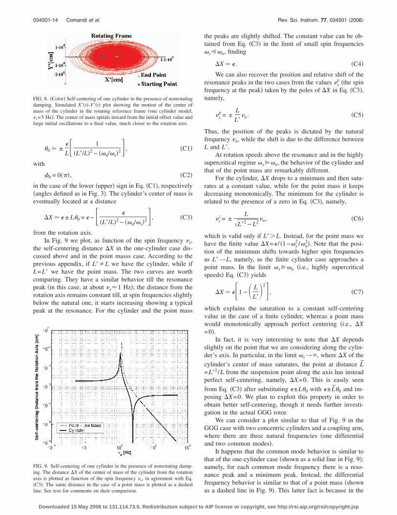
from the rotation axis.In Fig. 9 we plot, as function of the spin frequency �s,
the self-centering distance �X in the one-cylinder case dis-cussed above and in the point masss case. According to theprevious appendix, if L��L we have the cylinder, while ifL=L� we have the point mass. The two curves are worthcomparing. They have a similar behavior till the resonancepeak �in this case, at about �s�1 Hz�; the distance from therotation axis remains constant till, at spin frequencies slightlybelow the natural one, it starts increasing showing a typicalpeak at the resonance. For the cylinder and the point mass
FIG. 8. �Color� Self-centering of one cylinder in the presence of nonrotatingdamping. Simulated X��t�-Y��t� plot showing the motion of the center ofmass of the cylinder in the rotating reference frame �one cylinder model,�s=5 Hz�. The center of mass spirals inward from the initial offset value andlarge initial oscillations to a final value, much closer to the rotation axis.
FIG. 9. Self-centering of one cylinder in the presence of nonrotating damp-ing. The distance �X of the center of mass of the cylinder from the rotationaxis is plotted as function of the spin frequency �s, in agreement with Eq.�C3�. The same distance in the case of a point mass is plotted as a dashed
line. See text for comments on their comparison.Downloaded 15 May 2006 to 131.114.73.5. Redistribution subject to
the peaks are slightly shifted. The constant value can be ob-tained from Eq. �C3� in the limit of small spin frequenciess�n, finding
�X � � . �C4�
We can also recover the position and relative shift of theresonance peaks in the two cases from the values �s
p �the spinfrequency at the peak� taken by the poles of �X in Eq. �C3�,namely,
�sp = ±
L
L��n. �C5�
Thus, the position of the peaks is dictated by the naturalfrequency �n, while the shift is due to the difference betweenL and L�.
At rotation speeds above the resonance and in the highlysupercritical regime s�n, the behavior of the cylinder andthat of the point mass are remarkably different.
For the cylinder, �X drops to a minimum and then satu-rates at a constant value, while for the point mass it keepsdecreasing monotonically. The minimum for the cylinder isrelated to the presence of a zero in Eq. �C3�, namely,
�sz = ±
L�L�2 − L2
�n, �C6�
which is valid only if L��L. Instead, for the point mass wehave the finite value �X=� / �1−s
2 /n2�. Note that the posi-
tion of the minimum shifts towards higher spin frequenciesas L�→L, namely, as the finite cylinder case approaches apoint mass. In the limit s�n �i.e., highly supercriticalspeeds� Eq. �C3� yields
�X � ��1 − � L
L� 2� , �C7�
which explains the saturation to a constant self-centeringvalue in the case of a finite cylinder, whereas a point masswould monotonically approach perfect centering �i.e., �X=0�.
In fact, it is very interesting to note that �X dependsslightly on the point that we are considering along the cylin-der’s axis. In particular, in the limit s→�, where �X of the
cylinder’s center of mass saturates, the point at distance L=L�2 /L from the suspension point along the axis has insteadperfect self-centering, namely, �X=0. This is easily seen
from Eq. �C3� after substituting �±L�0 with �± L�0 and im-posing �X=0. We plan to exploit this property in order toobtain better self-centering, though it needs further investi-gation in the actual GGG rotor.
We can consider a plot similar to that of Fig. 9 in theGGG case with two concentric cylinders and a coupling arm,where there are three natural frequencies �one differentialand two common modes�.
It happens that the common mode behavior is similar tothat of the one-cylinder case �shown as a solid line in Fig. 9�;namely, for each common mode frequency there is a reso-nance peak and a minimum peak. Instead, the differentialfrequency behavior is similar to that of a point mass �shown
as a dashed line in Fig. 9�. This latter fact is because in theAIP license or copyright, see http://rsi.aip.org/rsi/copyright.jsp
034501-15 Rotating accelerometer for EP tests. I. Rev. Sci. Instrum. 77, 034501 �2006�
differential mode the coupling arm oscillates and the cylin-ders’s centers of mass move in the horizontal plane with theopposite phase, while �i,o=0; under these conditions, theirmoment of inertia is irrelevant in determining the dynamics,which therefore is very much alike the case of a point mass.As a result, the �X of the GGG rotor for intermediate valuesof the spin frequency is characterized by one peak at lowfrequency, in correspondence to the differential mode, andtwo peaks and two minima, in correspondence to the com-mon modes. Instead, in the limit of very low and very highspin frequencies, it has a behavior similar to that displayed inFig. 9, depending on the values and directions assumed forthe initial offsets of the three bodies.
Thus, in order to obtain the best possible centering of thetest cylinders in the GGG rotor, one can either spin at afrequency close to the minima of the common modes, orabove both of them, in such a condition that the two cylin-ders are better centered on their own rotation axes than bothof them are, together, in a common mode. Self-centering onthe rotation axes is very important in order to reduce rotationnoise, because we are dealing with rapidly spinning macro-scopic bodies and aiming at measuring extremely small ef-fects. The issue therefore needs a careful investigation, andto this end realistic numerical simulations of the apparatusare an essential tool.
Finally, concerning the use of supercritical rotors for EPtesting, it is worth mentioning a frequently asked question:Would a relative displacement of the test bodies causedby an external force—such as that resulting from an EPviolation—be reduced by self-centering in supercritical rota-tion as it happens for the original offset �? The answer is“no” because the offset vector is fixed in the rotating frameof the system, while an external force gives rise to a dis-placement of the equilibrium position of the bodies in thenonrotating reference frame. In the presence of such a force,whirl motion will take place around the displaced position ofequilibrium. A numerical simulation, showing this importantfeature is reported and discussed in Ref. 11, PLA paper,p. 176.
1 R. V. Eötvös, D. Pekar, and E. Fekete, Ann. Phys. �N.Y.� 68, 11 �1922�.2
P. G. Roll, R. Krotov, and R. H. Dicke, Ann. Phys. �N.Y.� 26, 442 �1964�.Downloaded 15 May 2006 to 131.114.73.5. Redistribution subject to
3 V. B. Braginsky and V. I. Panov, Sov. Phys. JETP 34, 463 �1972�.4 Y. Su et al., Phys. Rev. D 50, 3614 �1994�.5 S. Baebler, B. R. Heckel, E. G. Adelberger, J. H. Gundlach, U. Schimidt,and H. E. Swanson, Phys. Rev. Lett. 83, 3585 �1999�.
6 T. Damour and A. M. Polyakov, Nucl. Phys. B 423, 532 �1994�; Gen.Relativ. Gravit. 26, 1171 �1994�.
7 E. Fischbach, D. E. Krause, C. Talmadge, and D. Tadic, Phys. Rev. D 52,5417 �1995�.
8 T. Damour, F. Piazza, and G. Veneziano, Phys. Rev. Lett. 89, 081601�2002�.
9 P. W. Worden, Jr. and C. W. F. Everitt, in Experimental Gravitation, Pro-ceedings of the “Enrico Fermi” International School of Physics, CourseLVI, edited by B. Bertotti �Academic, New York, 1973�; J. P. Blaser et al.,ESA SCI Report No. �96�5, 1996 �unpublished�; see also the STEP web-site http://einstein.stanford.edu/STEP/step2.html
10 See the MICROSCOPE website http://www.onera.fr/dmph/accelerometre/index.html
11 A. M. Nobili, D. Bramanti, G. L. Comandi, R. Toncelli, E. Polacco, andM. L. Chiofalo, Phys. Lett. A 318, 172 �2003�; “Galileo Galilei” �GG�,Phase A Report, ASI �November 1998�, 2nd ed. January 2000. A. M.Nobili, D. Bramanti, G. Comandi, R. Toncelli, E. Polacco, and G. Catas-tini, Phys. Rev. D 63, 101101 �2001�; for a review see, e.g., Ref. 12; seealso the GG website http://eotvos.dm.unipi.it/nobili
12 A. M. Nobili, in Recent Advances in Metrology and Fundamental Con-stants, Proceedings of the “Enrico Fermi” International School of Physics,Course CXLVI, edited by T. J. Quinn, S. Leschiutta, and P. Tavella �IOSPress, 2001�, p. 609.
13 W. Li, http://linkage.rockfeller/edu/wli/1fnoise14 A. M. Nobili, D. Bramanti, G. L. Comandi, R. Toncelli, and E. Polacco,
New Astron. 8, 371 �2003�.15 G. L. Comandi, A. M. Nobili, D. Bramanti, R. Toncelli, E. Polacco, and
M. L. Chiofalo, Phys. Lett. A 318, 213 �2003�.16 A. M. Nobili, D. Bramanti, G. L. Comandi, R. Toncelli, E. Polacco, and
M. L. Chiofalo, in Proceedings of the XXXVIIIth Rencontre de MoriondGravitational Waves and Experimental Gravity, edited by J. Dumarchezand J. Tran Thanh Van �The Gioi, Vietnam, 2003�, p. 371.
17 G. L. Comandi, A. M. Nobili, R. Toncelli, and M. L. Chiofalo, Phys. Lett.A 318, 251 �2003�.
18 J. P. Den Hartog, Mechanical Vibrations �Dover, New York, 1985�.19 S. H. Crandall, in Nonlinear Dynamics and Stochastic Mechanics, edited
by W. Kliemann and N. S. Namachchivaya �CRC, Boca Raton, FL, 1995�.20 G. Genta, Vibration of Structures and Machines �Springer-Verlag, New
York, 1993�.21 S. H. Crandall and A. M. Nobili, http://eotvos.dm.unipi.it/nobili/ggweb/
crandall22 A. M. Nobili et al., Class. Quantum Grav. 16, 1463 �1999�.23 A. M. Nobili, G. L. Comandi, S. Doravari, D. Bramanti, E. Polacco, and F.
Maccarrone �unpublished�.24 This concept was originally introduced by G. C. Wigner and V. F.
Weisskopf.25 G. L. Comandi, Ph.D. thesis, University of Pisa, 2004; http://
eotvos.dm.unipi.it/nobili/comandi_thesis
AIP license or copyright, see http://rsi.aip.org/rsi/copyright.jsp


![Galileo galilei[1]](https://static.fdocuments.us/doc/165x107/558cd655d8b42a87228b464b/galileo-galilei1.jpg)