Dynamic Water Vapor Permeance of Building Materials and...
8
DYNAMIC WATER VAPOR PERMEANCE OF BUILDING MATERIALS AND THE BENEFITS TO BUILDINGS BY MARYSUSAN COUTURIER AND CRAIG BOUCHER W.R. GRACE & CO. 62 Whittemore Ave., Cambridge, MA 02140. Phone: 617498 4509 • Email: [email protected] and [email protected] 26 TH RCI I NTERNATIONAL C ONVENTION AND T RADE S HOW • A PRIL 712, 2011 C OUTURIER AND B OUCHER • 13
Transcript of Dynamic Water Vapor Permeance of Building Materials and...
DYNAMIC WATER VAPOR PERMEANCE OF BUILDING
MATERIALS AND THE BENEFITS TO BUILDINGS
BY MARYSUSAN COUTURIER AND CRAIG BOUCHER
W.R. GRACE & CO. 62 Whittemore Ave., Cambridge, MA 02140.
Phone: 617498 4509 • Email: [email protected] and [email protected]
26 T H RC I I N T E R N AT I O N A L C O N V E N T I O N A N D T R A D E S H O W • A P R I L 7 1 2 , 2011 C O U T U R I E R A N D B O U C H E R • 13

ABSTRACT
Knowledge of building materials’ water vapor transmission properties is critical to prop-er building design. The standard version of ASTM E96 does not adequately describe water vapor transmission properties of building materials. Simple modifications to the current standard can be made that allow for measurement of water vapor permeance over a range of relative humidity.
Information on the benefits of building materials that have a variable vapor permeance in typical exterior-wall assemblies will be provided. Examples of wall assemblies in various climate zones to help validate the benefits of variable vapor permeance when exposed to dif-ferent relative humidity levels will be explained.
SPEAKER
MARYSUSAN COUTURIER — W.R. GRACE & CO.
MARYSUSAN COUTURIER is a senior research chemist with W.R. Grace. She has over 20 years of experience working in research and development with polymers. Her work has included structural adhesives for the automotive and construction industry, sealants for the food packaging industry, and air barriers for the construction industry. She received her B.A. in chemistry form Regis College, completed her master’s in plastics engineering at the University of Massachusetts, and is a member of the Society of Plastics Engineers. She holds two patents on polymer compositions.
CRAIG BOUCHER — W.R. GRACE & CO.
CRAIG BOUCHER has worked in the construction product industry for over 10 years. He has witnessed ASTM E96 testing and several other building material tests at third-party labs and participates in the ASTM committees that developed the standards. He is on the technical committee and board of directors of the Air Barrier Association of America and participates in the Underwriters Laboratories of Canada Committee on Air Barrier Materials and Systems. Mr. Boucher has made presentations on building materials at CSI and AIA meetings and trade shows. He has a B.S. in civil engineering from Worcester Polytechnic Institute and is a LEED Accredited Professional.
14 • C O U T U R I E R A N D B O U C H E R 26 T H RC I I N T E R N AT I O N A L C O N V E N T I O N A N D T R A D E S H O W • A P R I L 7 1 2 , 2011

DYNAMIC WATER VAPOR PERMEANCE OF BUILDING
MATERIALS AND THE BENEFITS TO BUILDINGS
BACKGROUND Figure 1 – Air leaking into building. The use of air bar-
riers to prevent air leakage, moisture problems, and energy loss is becoming accepted in the con-struction industry. Air barriers minimize hot air leaking into the building in the warmer summer months due to thermal gradients, as shown in Figure 1. Air barriers also limit Figure 2 – Air leaking out
of building. warm air from leaking out of the building in the colder winter months, as shown in Figure 2.
Measurement of air resistance of air barrier materials and assemblies is pretty straightforward, with the most common methods being ASTM E2178 and ASTM E2357. Depending upon the type of materi-al being used, air barriers can have varying water vapor permeance, from impermeable to permeable. Understanding the water vapor permeance of the air barrier being used in a building envelope is very impor-tant to ensure the building envelope does not trap moisture in undesirable locations or materials that can lead to moisture dam-age of the building envelope.
Water vapor permeance is calculated from the water vapor transmission rate (WVTR) through a material and is not as straightforward a property to measure as it would appear. McCullough1 compared five standard test methods for measuring WVTR of materials: ASTM E96B, ASTM E96BW, JSL 1099, ASTM F1868, and ASTM F2298. She concluded that although there were some correlations within the test results, the data from one test to another are not comparable, and the reason why the differ-ences exist is not clearly understood. For the most part, the building science industry tends to use ASTM E96 for measuring WVTR of building materials. In simple terms, this method measures the rate of water vapor transmitting through a materi-al when exposed to a vapor drive.
ASTM E96 basi-cally uses a dish with the material being evaluated sealed to the top of the dish. As shown in Figure 3, ASTM E96 provides six test conditions that can be used to eval-uate the material. Each test condition may not provide similar results for a material. There is a wide range in tem-perature and relative humidity (RH) that can greatly affect gas transport properties of materials.
In the Desiccant Method, the RH varies from 0% to 50%, and the vapor drive is into the cup. For the Water Method (or wet cup), the RH varies from 50% to 100%, and the vapor drive is out of the cup. Conditions C, D, and E use either the Desiccant or Water Methods with elevated temperatures. Increasing the temperature for polymeric materials may cause a change in the thermal expansion, gas diffusion, and solubility coef-ficients. Therefore, results from one temperature and material type will not correlate with anoth-
er test condition or material. The 2009 International Building Code
(IBC)2 provides three levels of classification for vapor retarders and permeance, based on ASTM E96A, the Desiccant Method. Type I has water vapor permeance of ≤0.1 perms. Type II is >0.1 and ≤1 perms, and Type III is
Figure 3 – ASTM E96 test conditions.
26 T H RC I I N T E R N AT I O N A L C O N V E N T I O N A N D T R A D E S H O W • A P R I L 7 1 2 , 2011 C O U T U R I E R A N D B O U C H E R • 15

Figure 4 – 2009 IBC classifications for water vapor permeance and test conditions of vapor retarders.
Figure 5 – Basic chamber conditions.
All of the testing was done under isothermal conditions.
>1 and ≤10 perms. The 2009 IBC also defines a vapor permeable membrane as a membrane that permits the passage of moisture vapor and has a permeance greater or equal to 5 perms based on ASTM E96A, the Desiccant Method. As shown in Figure 4, classifying based on the dry cup will not always reveal the material’s behav-ior under conditions of high relative humid-ity, which may be the more critical condi-tion. With some materials, one datum point will not provide sufficient information as to how the material will behave over the entire relative humidity range it will be exposed to in a building.
In order to determine how different air barrier material technologies performed from low to very high relative humidity exposures, a set of experiments was con-ducted. The air barrier technologies evalu-ated were these:
1. Asphaltic-based peel-and-stick membrane
2. Nonasphaltic-based peel-and-stick membrane
3. Liquid, spray-applied air barrier
16 • C O U T U R I E R A N D B O U C H E R
Figure 6 – Salt solutions and relative humidity conditions used in the experiment.
TEST PROCEDURE Simple modifications to
ASTM E96 can be employed to measure the water vapor perme-ance of a material at different relative humidity exposures. The technique used for this evalua-tion is based on Timusk3 and Kuishan4, using saturated salt solutions to create differing rela-tive humidity conditions inside and outside of the cup as shown in Figure 5. The saturated salt solutions were placed inside of the cup with the material being evaluated sealed to the top of the
cup. The cups were placed in a chamber. The relative humidity of the chamber was controlled to create the relative humidity condition outside of the cup. By creating differing relative humidity conditions both inside the cup and outside of the cup (i.e., in the chamber), a num-ber of varying test sce-narios can be run.
ASTM E104 lists equilibrium relative humidity values for selected saturated aque-ous salt solutions and provides guidance on how to make the solu-tions. Young5 and Dean6
are additional references for humidity control using saturated salt solutions. The standard Desiccant and Water Methods from ASTM E96
Figure 7 – were used in conjunction Measurement of with six additional exper-
low to high. The test conditions used are listed in Figure 6.
Since the hydrating reaction for these salts is exothermic, the salt solutions were created a mini-mum of one day prior to starting the tests. This was done to avoid confounding the results with tem-perature variations. The relative humidity inside the cup was mea-sured using a blank cup with the same salt solution covered with an impermeable membrane, as shown in Figure 7.
It is important to note that the salt solu-tions can be corrosive, so the use of plastic or glass containers and not steel or alu-minum is recommended to prevent corro-sion in the cup that could impact the data. The process for measuring WVTR per ASTM E96 is to weigh the cups to determine if water vapor has exited or entered the cup. Introduction of corrosion to the testing could affect the weight measurements and, therefore, the WVTR data.
The cups and test chambers were stored in a laboratory controlled at 70ºF (21ºC) and 50% RH. For the test chambers, stan-dard plastic coolers or ice chests were used. A small, 5-cfm fan was mounted within the coolers to maintain adequate air circulation as prescribed in ASTM E96, between 0.066 and 1 ft/second, as shown in Figure 8. The temperature and relative humidity inside the chamber were monitored using a Dickson data logger. This allowed for con-tinual measurement of temperature and rel-ative humidity for the duration of the exper-iments. The cups rested on a plastic rack in
the cooler above the saturated salt solu-tion. The cups were weighed twice a day, and water vapor per-meance was calculat-ed as prescribed in ASTM E96. The weight loss was plot-ted over time, and the slope of the line was
relative humidity imental relative humidity inside of the cup. conditions, ranging from
26 T H RC I I N T E R N AT I O N A L C O N V E N T I O N A N D T R A D E S H O W • A P R I L 7 1 2 , 2011

used to calculate the water vapor transmission rate.
For some materials, a change in slope with time existed. When this occurred, the final slope was used for the water vapor permeance calcula-tions. Reasons for the change in slope will be discussed later in the paper. The water vapor permeance is calculated by dividing the WVTR by the product of the satura-tion water vapor pressure times the change in rela-tive humidity.
RESULTS
ASTM E96 to characterize a material’s performance would not be accurate. In this example, under 2009 IBC, the air barrier mate-rial is characterized as a Type II vapor retarder with a permeance of >0.1 and <1. However, under conditions of high humid-ity, this air barrier mater-ial is not a vapor retarder, but permeable to water
Figure 8 – Test chambers and fan used inside test chambers to maintain proper air circulation in accordance with ASTM E96 requirements.
Results of water vapor permeance vs. relative humidity for three air barriers are shown in Figure 9. Not all air barriers per-form the same as they are exposed to differ-ent relative humidity conditions. Depending upon the material type, either a static or dynamic response can be obtained. Static materials exhibit a linear response to rela-tive humidity, and dynamic materials exhibit a nonlinear response to relative humidity in the case of material 3 (liquid, spray-applied air barrier), an exponential response to relative humidity.
DISCUSSION For static-type materials, water vapor
permeance is based solely on Fickean diffu-sion. Measuring permeance under dry cup conditions will give a fairly accurate predic-tion under wet cup or other relative humid-ity conditions. Materials that show a dynamic response to relative humidity exhibit both a diffusion and solubility inter-action coefficient. Gretton7 and Chang8 also discuss this non-Fickean behavior. Materials that contain polar groups will exhibit molecular attractions with the water vapor. This dual effect is the explanation for the slope change in the WVTR mentioned earlier in the paper; one is for diffusion, and the other is for solubility. This solubility or inter-action coefficient changes with the amount of water vapor present and is dependent upon the chemistry of the material. In this situation, basing performance upon dry cup results could result in inaccurate
Figure 9 – Results of water vapor permeance vs. relative humidity testing for three types of air barrier materials.
recommendations for humid conditions. For example, Figure 4 shows the classi-
fication and test methods for vapor retarders in the 2009 IBC. Figure 10 shows vapor permeance testing results for 1) asphaltic-based, self-adhered air barrier and 2) nonasphaltic-based, self-adhered air barrier, in addition to the 2009 IBC classifi-cation and test methods for vapor retarders. Basing the vapor retarder classification of the materials shown in this example solely on water vapor permeance using the Desiccant Method of ASTM E96 is accept-able for these materials that have a static response to relative humidity.
For static materials, using the Water Method or Desiccant Method of ASTM E96 is acceptable because the water vapor per-meance does not change drastically with relative humidity. However, the same is not true for materials that have a dynamic water vapor permeance response to relative humidity. Referring to Figure 11, using the Desiccant Method of
vapor. At an average RH of 75%, the water vapor per-meance is 12 perms, and at 90% RH, the water vapor permeance is around 30 perms. Clearly, this is not a vapor retarder, but quite the
opposite at high levels of relative humidity. Characterizing a material’s behavior
under conditions of low relative humidity appears to be of much less importance than under high relative humidity conditions. It is under high moisture conditions where vapor drive and building design are critical.
Figure 10 – Examples of static response to relative humidity.
Figure 11 – Example of potential incorrect characterization of a material’s water vapor permeance when only one datum point is evaluated.
26 T H RC I I N T E R N AT I O N A L C O N V E N T I O N A N D T R A D E S H O W • A P R I L 7 1 2 , 2011 C O U T U R I E R A N D B O U C H E R • 17
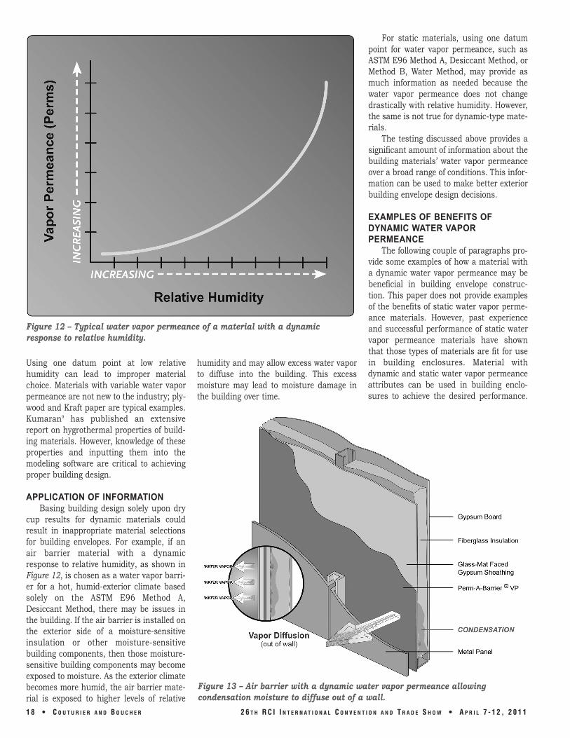
Figure 12 – Typical water vapor permeance of a material with a dynamic response to relative humidity.
Using one datum point at low relative humidity can lead to improper material choice. Materials with variable water vapor permeance are not new to the industry; ply-wood and Kraft paper are typical examples. Kumaran9 has published an extensive report on hygrothermal properties of build-ing materials. However, knowledge of these properties and inputting them into the modeling software are critical to achieving proper building design.
APPLICATION OF INFORMATION Basing building design solely upon dry
cup results for dynamic materials could result in inappropriate material selections for building envelopes. For example, if an air barrier material with a dynamic response to relative humidity, as shown in Figure 12, is chosen as a water vapor barri-er for a hot, humid-exterior climate based solely on the ASTM E96 Method A, Desiccant Method, there may be issues in the building. If the air barrier is installed on the exterior side of a moisture-sensitive insulation or other moisture-sensitive building components, then those moisture-sensitive building components may become exposed to moisture. As the exterior climate becomes more humid, the air barrier mate-rial is exposed to higher levels of relative
humidity and may allow excess water vapor to diffuse into the building. This excess moisture may lead to moisture damage in the building over time.
For static materials, using one datum point for water vapor permeance, such as ASTM E96 Method A, Desiccant Method, or Method B, Water Method, may provide as much information as needed because the water vapor permeance does not change drastically with relative humidity. However, the same is not true for dynamic-type mate-rials.
The testing discussed above provides a significant amount of information about the building materials’ water vapor permeance over a broad range of conditions. This infor-mation can be used to make better exterior building envelope design decisions.
EXAMPLES OF BENEFITS OF DYNAMIC WATER VAPOR PERMEANCE
The following couple of paragraphs pro-vide some examples of how a material with a dynamic water vapor permeance may be beneficial in building envelope construc-tion. This paper does not provide examples of the benefits of static water vapor perme-ance materials. However, past experience and successful performance of static water vapor permeance materials have shown that those types of materials are fit for use in building enclosures. Material with dynamic and static water vapor permeance attributes can be used in building enclo-sures to achieve the desired performance.
Figure 13 – Air barrier with a dynamic water vapor permeance allowing condensation moisture to diffuse out of a wall.
18 • C O U T U R I E R A N D B O U C H E R 26 T H RC I I N T E R N AT I O N A L C O N V E N T I O N A N D T R A D E S H O W • A P R I L 7 1 2 , 2011

Understanding the attribute of the material with respect to water vapor permeance is important to ensure the material chosen is suitable for the building envelope design.
For the first example, consider a build-ing in Minnesota. In the winter months, most of Canada and the United States, including Minnesota, will experience weath-er conditions in which the exterior of the structure is colder and less humid than the interior. These differences in temperature and relative humidity can lead to air and moisture drive from the interior of a build-ing toward the colder and drier exterior con-ditions.
If there is a small air leak in the air bar-rier assembly, at an exterior outlet box or light fixture, for example, then air will leak out of the building. As warm, moist air moves from the interior toward the exterior, the air may cool down as it passes through air-permeable insulation materials and may potentially reach its dew point. If the dew point is reached in the wall assembly, then water in the air will condense at the interi-or surface of the gypsum sheathing as shown in Figure 13. If the gypsum sheath-ing gets saturated by the condensation, then an air barrier applied onto the exterior surface of the gypsum sheathing will be
exposed to a high level of relative humidity – effectively 100% RH.
The previous portion of this paper iden-tified materials, such as air barriers, that have a dynamic water vapor permeance when exposed to different levels of relative humidity. An air barrier with a dynamic water vapor permeance that increases as relative humidity increases may be benefi-cial for the condition shown in Figure 13. As the gypsum sheathing gets wet due to con-densation, the air barrier will increase its water vapor permeance to allow the mois-ture to diffuse out of the wall. This attribute of the air barrier may help dry the exterior wall assembly in the short term, but an air leak that results in condensation in the wall assembly must be repaired to ensure the building does not experience excessive moisture damage.
Another benefit of an air barrier with a dynamic water vapor permeance is facilitat-ing a dry wall assembly, should there be a water leak into the structure. Bulk water intrusion into the wall assembly may occur at a defect in window installation, as shown in Figure 14, or other penetrations through the wall. If the fiberglass insulation and OSB or plywood get wet due to a water leak in the wall, then the water vapor permeance
of an air barrier, which increases in water vapor permeance as relative humidity levels increase, will increase to help dry out the wall. The air barrier at this point will allow water vapor to diffuse out through the wall to facilitate drying of the wall. Facilitating rapid drying of the wall could help prevent mold growth, rot, and decay of moisture-sensitive elements within the wall assembly if the water leak is repaired quickly.
It is important to point out that water vapor diffusion, even at high water vapor permeance levels, is relatively slow in terms of moving large quantities of moisture. Water vapor diffusion will not remove enough moisture from the wall cavity to keep up with a liquid water leak into the building envelope. The liquid water leak will allow far more moisture and water to enter the wall cavity in the example shown in Figure 14 than water vapor diffusion will be able to remove under normal conditions. Therefore, as indicated in the paragraph above, the water leak will need to be repaired quickly to prevent significant dam-age in the building envelope.
CONCLUSION Materials used in the construction of
building envelopes may have a dynamic or static water vapor permeance response when exposed to varying levels of relative humidity. Measuring the water vapor per-meance of a material over a wide range of relative humidity levels is achievable. Understanding the water vapor permeance response of a material to different relative humidity levels is important in selecting materials for the building enclosure.
REFERENCES 1. E. McCullough, M. Kwon, and H.
Shim. “A Comparison of Standard Methods for Measuring Water Va-pour Permeability of Fabrics,” Measurement Science and Technology. 14: 1402-1408. 2003.
2. ICC International Building Code, 2007 Supplement. IBC-4.
3. P.C. Timusk, K.D. Pressnail, and V.F. Striesky. “Moisture-Related Properties of Oriented Strand Board.” 10DBMC International Conference on Durability of Building Materials and Components, Lyon. 2005.
4. L. Kuishan, Z. Xu, and G. Jun. “Experimental Investigation of Hy-grothermal Parameters of Building Materials Under Isothermal Con-
2 6 T H R C I I N T E R N A T I O N A L C O N V E N T I O N A N D T R A D E S H O W • A P R I L 7 1 2 , 2 0 1 1 C O U T U R I E R A N D B O U C H E R • 1 9
Figure 14 – Air barrier with a dynamic water vapor permeance allowing moisture from a water leak to diffuse out of a wall.

5.
6.
7.
ditions.” Journal of Building Physics. Vol. 32, No. 4. 2009. J.F. Young. “Humidity Control in the Laboratory Using Salt Solutions - A Review.” Journal of Applied Chemistry. Vol. 17. 1967. J.A. Dean. Lange’s Handbook of Chemistry (15th Edition). McGraw-Hill, Table 11.4. 1999. J.C. Gretton, D.B. Brook, H.M.
8.
9.
301-310. 1996. S.C. Chang, S. Sask, and N.B. Hutcheon. “Dependence of Water Vapor Permeability on Temperature and Humidity.” National Research Council, Canada, Division of Building Research, Research Paper No. 21. 1956. M.K. Kumaran, J. Lackey, N. Normandin, D. van Reenen, and F.
Dyson, and S.C. Harlock. “A Correlation Between Test Methods Used to Measure Moisture Vapour Transmission Through Fabrics.” Journal of Coated Fabrics, 25, pp
Tariku. “Summary Report from Task 3 of MEWS Project.” Institute for Research in Construction, National Research Council, Ottawa, Canada, (NRCC45369), pp 1-68. 2002.
20 • C O U T U R I E R A N D B O U C H E R 26 T H RC I I N T E R N AT I O N A L C O N V E N T I O N A N D T R A D E S H O W • A P R I L 7 1 2 , 2011