Dynamic Response of Two Adjacent Structures … Response of Two Adjacent Structures ... seismic...
10
© 2015 IJEDR | Volume 3, Issue 2 | ISSN: 2321-9939 IJEDR1502206 International Journal of Engineering Development and Research ( www.ijedr.org) 1253 Dynamic Response of Two Adjacent Structures Connected by Friction Damper (Coulomb Friction Model) 1 Shobhika 1 M.Tech. Student 1 Civil Engineering Department 1 M.M. Engineering College, Mullana, Ambala, India ________________________________________________________________________________________________________ Abstract - In the last few years, efforts were carried out to develop the concept of energy dissipation in structures to bring it into an applicable technology. The conventional structural systems are highly unlikely to provide adequate performance in the event of a major earthquake. Several devices based on different energy dissipation principles have been developed and implemented worldwide. Connecting the adjacent structures with passive energy dissipation devices has attracted the attention of many researchers due to its ability in mitigating the seismic responses. Friction damper is one of the energy dissipating devices which dissipate the energy during earthquake. Further, effectiveness of dampers in terms of the reduction of structural responses namely, displacement, velocity and acceleration is investigated using Newmark’s step by step method. A parametric study is also conducted to investigate the optimum slip force of the damper. In this study, seismic responses of two connected structures are compared with the seismic responses of a single structure. Index Terms – Adjacent structures, friction damper, seismic response, slip mode, non-slip mode. ________________________________________________________________________________________________________ I. INTRODUCTION Over the past few decades world has experienced numerous devastating earthquakes, resulting in increased number of loss of human life due to collapse of buildings and severe structural damages. Occurrence of such damages during earthquakes clearly demonstrates the high seismic hazards and the structures like residential buildings, lifetime structures need to be designed very carefully to protect from earthquakes. Various experiences show that for the development of new construction, establishing earthquake resistant regulations and their provision is the critical safeguard against earthquake induced damage. It is necessary to evaluate and strengthen the existing structure based on evaluation criteria before an earthquake. To protect structures from significant damage under such severe earthquakes has become an important topic in structural engineering. Conventionally, structures are designed to resist dynamic forces through a combination of strength, deformability and energy absorption. Sometimes structures designed with these methods are susceptible to strong earthquake motions. In order to avoid such critical damages, structural engineers are working to figure out differ types of structural system that can withstand strong motions. Structural vibration control, as an advanced technology in engineering, is to implement energy dissipation devices or control systems into structures to reduce excessive structural vibrations, enhance human comfort and prevent catastrophic structural failure due to strong winds and earthquakes. Structural control is necessary because big buildings require more protection. In big buildings, lots of material is used. Many historical buildings are destroyed due to large or sudden earthquake. The concept of structural control theories and devices has been recently developed and introduced to large-scale civil engineering structures. Structural control technology can also be used for retrofitting of historical structures especially against earthquakes. The generally adopted approach to vibration control of structures is with vibration damping that is added to a structure either passively or actively. The damping dissipates some of the vibration energy of a structure by transforming it directly to the connected structure. Connecting the adjacent structures with energy dissipation devices has attracted the attention of many researchers due to its ability in mitigating the dynamic responses as well as to reduce the chances of pounding. Various methods of structural control are adopted as earthquake protective system. Passive control, active control, semi-active control and hybrid system are the methods of structural control system. A passive control system consists of one or more devices. These devices are embedded or attached to a structure, designed to modify the stiffness or the damping of the structure in an appropriate manner without requiring a external power source to operate, developing the control forces opposite to the motion of controlled structural system. Passive control system is generally adopted as compare to other systems because it consumes no energy, relatively less expensive .One of the passive energy dissipation devices is friction damper. Friction dampers are simple in construction and offer repeatable performance at low cost. Friction dampers can reduce the seismic responses of the innovative structures as well as the existing structures. Also, friction dampers need no repair or replacement before and after earthquake. Friction dampers perform better when frequencies of the connected structures are well separated. In this paper, the seismic response of structures connected with a friction damper is investigated under given earthquake excitation.
Transcript of Dynamic Response of Two Adjacent Structures … Response of Two Adjacent Structures ... seismic...
© 2015 IJEDR | Volume 3, Issue 2 | ISSN: 2321-9939
IJEDR1502206 International Journal of Engineering Development and Research (www.ijedr.org) 1253
Dynamic Response of Two Adjacent Structures
Connected by Friction Damper (Coulomb Friction
Model)
1Shobhika 1M.Tech. Student
1Civil Engineering Department 1M.M. Engineering College, Mullana, Ambala, India
________________________________________________________________________________________________________
Abstract - In the last few years, efforts were carried out to develop the concept of energy dissipation in structures to bring
it into an applicable technology. The conventional structural systems are highly unlikely to provide adequate performance
in the event of a major earthquake. Several devices based on different energy dissipation principles have been developed
and implemented worldwide. Connecting the adjacent structures with passive energy dissipation devices has attracted the
attention of many researchers due to its ability in mitigating the seismic responses. Friction damper is one of the energy
dissipating devices which dissipate the energy during earthquake. Further, effectiveness of dampers in terms of the
reduction of structural responses namely, displacement, velocity and acceleration is investigated using Newmark’s step by
step method. A parametric study is also conducted to investigate the optimum slip force of the damper. In this study,
seismic responses of two connected structures are compared with the seismic responses of a single structure.
Index Terms – Adjacent structures, friction damper, seismic response, slip mode, non-slip mode. ________________________________________________________________________________________________________
I. INTRODUCTION
Over the past few decades world has experienced numerous devastating earthquakes, resulting in increased number of loss of
human life due to collapse of buildings and severe structural damages. Occurrence of such damages during earthquakes clearly
demonstrates the high seismic hazards and the structures like residential buildings, lifetime structures need to be designed very
carefully to protect from earthquakes. Various experiences show that for the development of new construction, establishing
earthquake resistant regulations and their provision is the critical safeguard against earthquake induced damage. It is necessary to
evaluate and strengthen the existing structure based on evaluation criteria before an earthquake. To protect structures from
significant damage under such severe earthquakes has become an important topic in structural engineering. Conventionally,
structures are designed to resist dynamic forces through a combination of strength, deformability and energy absorption.
Sometimes structures designed with these methods are susceptible to strong earthquake motions. In order to avoid such critical
damages, structural engineers are working to figure out differ types of structural system that can withstand strong motions.
Structural vibration control, as an advanced technology in engineering, is to implement energy dissipation devices or control
systems into structures to reduce excessive structural vibrations, enhance human comfort and prevent catastrophic structural
failure due to strong winds and earthquakes. Structural control is necessary because big buildings require more protection. In big
buildings, lots of material is used. Many historical buildings are destroyed due to large or sudden earthquake. The concept of
structural control theories and devices has been recently developed and introduced to large-scale civil engineering structures. Structural control technology can also be used for retrofitting of historical structures especially against earthquakes. The generally
adopted approach to vibration control of structures is with vibration damping that is added to a structure either passively or
actively. The damping dissipates some of the vibration energy of a structure by transforming it directly to the connected structure.
Connecting the adjacent structures with energy dissipation devices has attracted the attention of many researchers due to its ability
in mitigating the dynamic responses as well as to reduce the chances of pounding.
Various methods of structural control are adopted as earthquake protective system. Passive control, active control, semi-active
control and hybrid system are the methods of structural control system. A passive control system consists of one or more devices.
These devices are embedded or attached to a structure, designed to modify the stiffness or the damping of the structure in an
appropriate manner without requiring a external power source to operate, developing the control forces opposite to the motion of
controlled structural system. Passive control system is generally adopted as compare to other systems because it consumes no
energy, relatively less expensive .One of the passive energy dissipation devices is friction damper. Friction dampers are simple in
construction and offer repeatable performance at low cost. Friction dampers can reduce the seismic responses of the innovative
structures as well as the existing structures. Also, friction dampers need no repair or replacement before and after earthquake.
Friction dampers perform better when frequencies of the connected structures are well separated. In this paper, the seismic
response of structures connected with a friction damper is investigated under given earthquake excitation.

© 2015 IJEDR | Volume 3, Issue 2 | ISSN: 2321-9939
IJEDR1502206 International Journal of Engineering Development and Research (www.ijedr.org) 1254
Figure 1 Friction Damper Device (www.zhanyichen.wordpress.com)
II. MATHEMATICAL FORMULATION
Assumptions and Limitations
Some assumptions are necessary to highlight the important characteristics of friction damper connecting adjacent structures
and to make problem manageable. Two adjacent structures are assumed to be symmetric structures with their symmetric planes in
alignment. The ground motion is assumed to occur in one direction in the symmetric planes of the structures so that the problem
can be simplified as two dimensional problem. Structure is modeled as a linear single-degree of freedom system where the mass is
concentrated at floor of the structure and stiffness is provided by the walls or columns. These assumptions indicate that due to
significant increase of energy absorbing capacity, the structures are able to remain elastic. It is also assumed that the floor
elevations are same for both structures and two neighbouring floors are connected by a damper device. Both structures are
assumed to be subjected to the same base acceleration. Any effects due to spatial variations of the ground motion or due to soil-
structure interactions are neglected.
A SDOF Structure connected with friction damper
Consider a structure connected with friction damper. The structure is idealized as single -degree-of-freedom system. Let m, c,
k be the mass, damping coefficient and stiffness respectively as shown in fig. 2(b). The system is subjected to earthquake motion.
��𝑔 be the ground acceleration and x is the displacement of a single structure.
a) A single structure equipped with friction damper
FRICTION
DAMPER
STRUCTURE

© 2015 IJEDR | Volume 3, Issue 2 | ISSN: 2321-9939
IJEDR1502206 International Journal of Engineering Development and Research (www.ijedr.org) 1255
(b) Mathematical Model
Figure 2 A SDOF structure equipped with friction damper.
Equation of motion for a SDOF structure
m�� + c�� + kx +fs sgn(��𝑟) = −m��𝑔 (1a)
or m�� + c�� + kx +µmg sgn(��𝑟) = −m��𝑔 (1b)
where sgn = signum function
fs = limiting frictional force in the damper (slip force)
= µmg
µ = friction coefficient
��𝑟 = sliding velocity of the damper
Two SDOF structures connected with friction damper Consider two adjacent structures connected with friction damper. The adjacent structures are idealized as single-degree-of-
freedom systems and referred to as Structure 1 and Structure 2 as shown in fig. 3(a). Let 𝑚1, 𝑐1, 𝑘1 be the mass, damping
coefficient and stiffness of the Structure 1, respectively. Similarly, 𝑚2, 𝑐2, 𝑘2 denote the corresponding parameters of Structure 2
as shown in fig. 3(b).
(a) Adjacent Structures connected with friction damper
FRICTION DAMPER
STRUCTURE 1 STRUCTURE 2
��𝑔
k
fs c
x
m

© 2015 IJEDR | Volume 3, Issue 2 | ISSN: 2321-9939
IJEDR1502206 International Journal of Engineering Development and Research (www.ijedr.org) 1256
(b) Mathematical Model
Figure 3 Structural model of two SDOF adjacent structures connected with friction damper
Let ω1 and ω2 be the natural frequencies of Structure 1 and Structure 2 respectively. Let λ and β be the mass and frequency
ratios of the two structures respectively.
Mass ratio (λ) = 𝑚1
𝑚2 (2)
Frequency ratio (β) = 𝜔2
𝜔1 (3)
When the adjacent structures, connected with the friction dampers, are excited to ground motion, the connected floors may
move together sticking with each other or slippage may occur between the floors which depend on the system parameters and the
excitation. When the slippage occurs, the floors are to be in slip mode and when the slippage does not occur, the floors are said to
be in non-slip mode.
To find out the seismic responses of the two structures, a numerical approach is employed in which the number of degrees-of-
freedom remains constant. This can be achieved by modeling the friction damper as a Coulomb friction model, which is very
approximate and still largely used because it is easy to handle and provides a sufficient level of approximation in engineering
problems.
fd = µ m g sgn(xr) (4)
where fd = frictional force of damper
ẋr = ��1 – ��2
The governing equations of motion of the two connected structures are given by 𝑚1��1+ 𝑐1��1+ 𝑘1𝑥1 + fs sgn(��𝑟) = −m1 ��𝑔 (5a)
or 𝑚2��2 + 𝑐2��2 + 𝑘2𝑥2 −fssgn(��𝑟) = −𝑚2��𝑔 (5b)
In matrix form
[𝑚1 00 𝑚2
] {��1
��2} + [
𝑐1 00 𝑐2
] {��1
��2} + [
𝑘1 00 𝑘2
] {𝑥1
𝑥2} =− [
𝑚1 00 𝑚2
] {11
} ��𝑔 – {− μm𝑔 𝑠𝑔𝑛(��2 − ��1) μm𝑔 𝑠𝑔𝑛(��2 − ��1)
} (6a)
or M�� + C�� + Kx = ML��𝑔 – 𝑓𝑑 (6b)
where fd = {− μ𝑚g 𝑠𝑔𝑛(��2 − ��1) μ𝑚g 𝑠𝑔𝑛(��2 − ��1)
}
L = {11
}, called unit vector
𝑐2 𝑘2
𝑐1 𝑘1
��𝑔
𝑥1
𝑥2
𝑚1 𝑚2
© 2015 IJEDR | Volume 3, Issue 2 | ISSN: 2321-9939
IJEDR1502206 International Journal of Engineering Development and Research (www.ijedr.org) 1257
where 𝑥1, ��1, ��1 are displacement, velocity and acceleration of Structure 1 respectively and ��𝑔 is the ground acceleration.
Similarly, x2, ��2, ��2 are the displacement, velocity and acceleration of Structure 2 respectively. The connected floors may move
together sticking with each other or slippage may occur between the two floors when the adjacent buildings, connected with
friction damper, are excited to ground motion. The floors are said to be in non-slip mode when the slippage does not occur and
they are said to be in slip mode when slippage occurs. The formulation of the equations for this system and the derivation of
equations of the two connected structures are
Non-slip mode
Both the structures vibrate together during the non-slip mode as a single-degree-of-freedom system under ground excitation.
If the frictional force in the damper is less than the limiting frictional force then the coupled system remains in the non-slip mode.
By considering the dynamic equilibrium of either structure 1 or 2, the frictional force in the damper can be obtained.
Thus, the non-slip mode of the damper is valid until the inequality hold good-
│𝑚1 (��1+��𝑔) + 𝑐1 ��1 + 𝑘1 𝑥1│≤ 𝑓𝑠 (6a)
or │𝑚2 (��2+��𝑔) + 𝑐2 ��2 + 𝑘2 𝑥2│≤ 𝑓𝑠 (6b)
Slip mode The system moves into the slip mode whenever the force in the friction damper attains its slip force. The condition for
initiation of slippage is
│𝑚1 (��1+��𝑔) + 𝑐1��1 + 𝑘1𝑥1│> 𝑓𝑠 (7a)
or │𝑚2(��2+��𝑔) + 𝑐2 ��2 + 𝑘2𝑥2│>𝑓𝑠 (7b)
Results and Discussions
The earthquake time history selected to examine the seismic behaviour of a single structure and two SDOF adjacent structures
is N00S component of Imperial Valley, 1940. The floor mass and stiffness is considered to be uniform for both the cases. Also,
the damping ratio of 5% is considered for a single structure as well as for two adjacent connected structures.
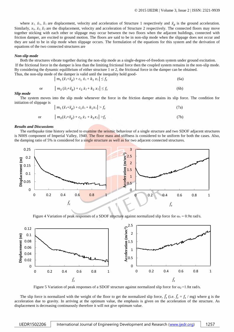
Figure 4 Variation of peak responses of a SDOF structure against normalized slip force for ω1 = 0.9π rad/s.
Figure 5 Variation of peak responses of a SDOF structure against normalized slip force for ω2 =1.8π rad/s.
The slip force is normalized with the weight of the floor to get the normalized slip force, 𝑓�� (i.e. 𝑓�� = 𝑓𝑠 / mg) where g is the
acceleration due to gravity. In arriving at the optimum value, the emphasis is given on the acceleration of the structure. As
displacement is decreasing continuously therefore it will not give optimum value.
0
0.05
0.1
0.15
0.2
0.25
0 0.2 0.4 0.6 0.8 1
Dis
pla
cem
ent
(m)
0
0.5
1
1.5
2
2.5
3
0 0.2 0.4 0.6 0.8 1
Acc
eler
ati
on
(m
/sec
2)
0
0.02
0.04
0.06
0.08
0.1
0.12
0 0.2 0.4 0.6 0.8 1
Dis
pla
cem
ent
(m)
0
0.5
1
1.5
2
2.5
0 0.2 0.4 0.6 0.8 1
Acc
eler
ati
on
(m
/sec
2)
𝑓�� 𝑓��
𝑓�� 𝑓��

© 2015 IJEDR | Volume 3, Issue 2 | ISSN: 2321-9939
IJEDR1502206 International Journal of Engineering Development and Research (www.ijedr.org) 1258
Figure 6 Time histories of the displacements, velocities and accelerations of a SDOF structure for Structure 1(ω1= 0.9π rad/s) and
for Structure 2 (ω2=1.8π rad/s), respectively.
-0.15
-0.1
-0.05
0
0.05
0.1
0.15
0.2
0 10 20 30 40
Dis
pla
cem
ent
(m)
Time (sec)
Structure 1
without damper
with damper
-0.1
-0.08
-0.06
-0.04
-0.02
0
0.02
0.04
0.06
0.08
0.1
0.12
0 10 20 30 40
Dis
pla
cem
ent
(m)
Time (sec)
Structure 2
-0.6
-0.4
-0.2
0
0.2
0.4
0.6
0.8
0 10 20 30 40
Vel
oci
ty (
m/s
ec)
Time (sec)
-0.8
-0.6
-0.4
-0.2
0
0.2
0.4
0.6
0.8
0 10 20 30 40
Vel
oci
ty (
m/s
ec)
Time (sec)
-2
-1.5
-1
-0.5
0
0.5
1
1.5
2
0 10 20 30 40
Acc
eler
ati
on
(m
/sec
2)
Time (sec)
-4
-3
-2
-1
0
1
2
3
0 10 20 30 40
Acc
eler
ati
on
(m
/sec
2)
Time (sec)
© 2015 IJEDR | Volume 3, Issue 2 | ISSN: 2321-9939
IJEDR1502206 International Journal of Engineering Development and Research (www.ijedr.org) 1259
Table 1: Seismic responses of a SDOF structure for a given earthquake when connected with friction damper (𝑓�� = 0.228,ω1=0.9π
rad/sec)
Earthquake
Displacement (m)
Velocity (m/sec)
Acceleration (m/sec2)
Imperial
Valley,
(1940)
Case 1
Case 2
Case 1
Case 2
Case 1
Case 2
0.20572
0.09899
(51.88)
0.61300
0.38212
(37.66)
1.65238
1.17522
(28.88)
Table 2: Seismic responses of a SDOF structure for a given earthquake when connected with friction damper (��𝒔 = 0.233,
ω2=1.8π rad/sec)
Earthquake
Displacement (m)
Velocity (m/sec)
Acceleration (m/sec2)
Imperial
Valley,
(1940)
Case 1
Case 2
Case 1
Case 2
Case 1
Case 2
0.09523
0.04285
(55.00)
0.55318
0.33538
(39.37)
3.06135
1.99495
(34.83)
Case 1 : Unconnected.
Case 2 : Connected.
Quantity within the parenthesis denotes the percentage reduction.
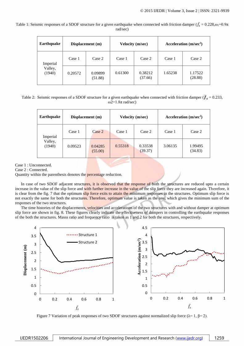
In case of two SDOF adjacent structures, it is observed that the response of both the structures are reduced upto a certain
increase in the value of the slip force and with further increase in the value of the slip force they are increased again. Therefore, it
is clear from the fig. 7 that the optimum slip force exits to attain the minimum responses in the structures. Optimum slip force is
not exactly the same for both the structures. Therefore, optimum value is taken as the one, which gives the minimum sum of the
responses of the two structures.
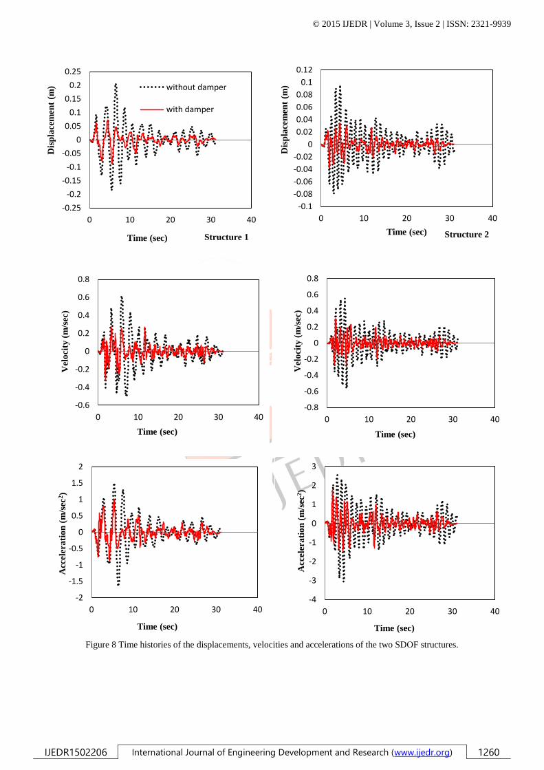
The time histories of the displacements, velocities and accelerations of the two structures with and without damper at optimum
slip force are shown in fig. 8. These figures clearly indicate the effectiveness of dampers in controlling the earthquake responses
of the both the structures. Masss ratio and frequency ratio is taken as 1 and 2 for both the structures, respectively.
Figure 7 Variation of peak responses of two SDOF structures against normalized slip force (λ= 1, β= 2).
0
0.5
1
1.5
2
2.5
3
3.5
4
0 0.2 0.4 0.6 0.8 1
Dis
pla
cem
ent
(m)
Structure 1
Structure 2
0
0.5
1
1.5
2
2.5
3
3.5
4
4.5
0 0.2 0.4 0.6 0.8 1
Acc
eler
ati
on
(m
/sec
2)
𝑓�� 𝑓��
© 2015 IJEDR | Volume 3, Issue 2 | ISSN: 2321-9939
IJEDR1502206 International Journal of Engineering Development and Research (www.ijedr.org) 1260
Figure 8 Time histories of the displacements, velocities and accelerations of the two SDOF structures.
-0.25
-0.2
-0.15
-0.1
-0.05
0
0.05
0.1
0.15
0.2
0.25
0 10 20 30 40
Dis
pla
cem
ent
(m)
Time (sec) Structure 1
without damper
with damper
-0.1
-0.08
-0.06
-0.04
-0.02
0
0.02
0.04
0.06
0.08
0.1
0.12
0 10 20 30 40
Dis
pla
cem
ent
(m)
Time (sec) Structure 2
-0.6
-0.4
-0.2
0
0.2
0.4
0.6
0.8
0 10 20 30 40
Vel
oci
ty (
m/s
ec)
Time (sec)
-0.8
-0.6
-0.4
-0.2
0
0.2
0.4
0.6
0.8
0 10 20 30 40
Vel
oci
ty (
m/s
ec)
Time (sec)
-2
-1.5
-1
-0.5
0
0.5
1
1.5
2
0 10 20 30 40
Acc
eler
ati
on
(m
/sec
2)
Time (sec)
-4
-3
-2
-1
0
1
2
3
0 10 20 30 40
Acc
eler
ati
on
(m
/sec
2)
Time (sec)
© 2015 IJEDR | Volume 3, Issue 2 | ISSN: 2321-9939
IJEDR1502206 International Journal of Engineering Development and Research (www.ijedr.org) 1261
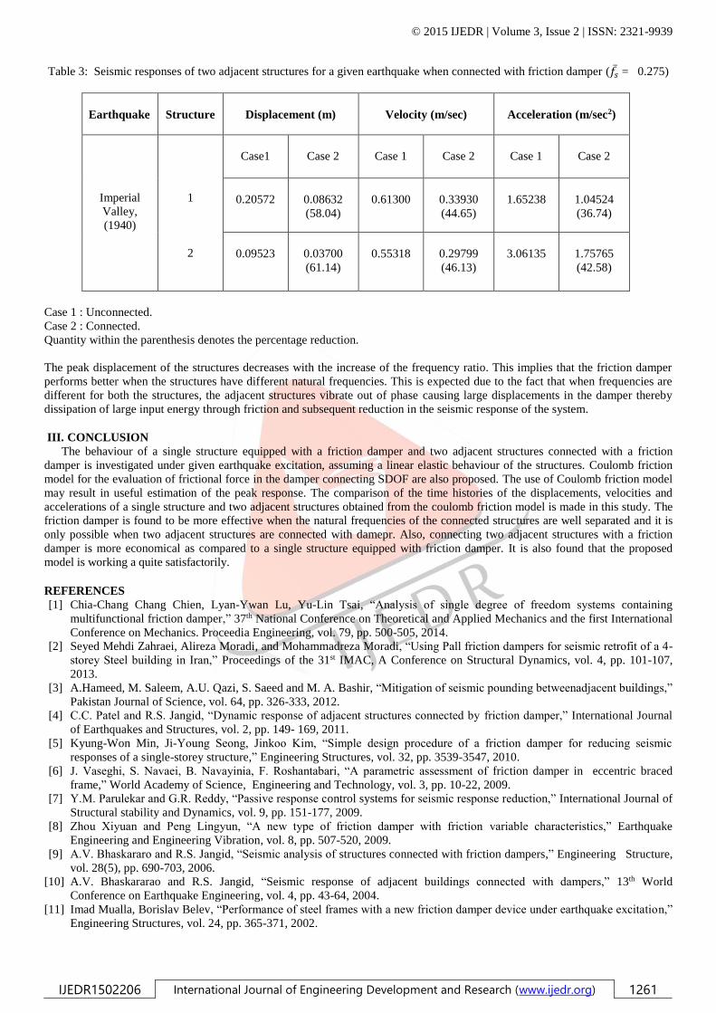
Table 3: Seismic responses of two adjacent structures for a given earthquake when connected with friction damper (𝑓�� = 0.275)
Earthquake
Structure
Displacement (m)
Velocity (m/sec)
Acceleration (m/sec2)
Imperial
Valley,
(1940)
1
2
Case1
Case 2
Case 1
Case 2
Case 1
Case 2
0.20572
0.08632
(58.04)
0.61300
0.33930
(44.65)
1.65238
1.04524
(36.74)
0.09523
0.03700
(61.14)
0.55318
0.29799
(46.13)
3.06135
1.75765
(42.58)
Case 1 : Unconnected.
Case 2 : Connected.
Quantity within the parenthesis denotes the percentage reduction.
The peak displacement of the structures decreases with the increase of the frequency ratio. This implies that the friction damper
performs better when the structures have different natural frequencies. This is expected due to the fact that when frequencies are
different for both the structures, the adjacent structures vibrate out of phase causing large displacements in the damper thereby
dissipation of large input energy through friction and subsequent reduction in the seismic response of the system.
III. CONCLUSION
The behaviour of a single structure equipped with a friction damper and two adjacent structures connected with a friction
damper is investigated under given earthquake excitation, assuming a linear elastic behaviour of the structures. Coulomb friction
model for the evaluation of frictional force in the damper connecting SDOF are also proposed. The use of Coulomb friction model
may result in useful estimation of the peak response. The comparison of the time histories of the displacements, velocities and
accelerations of a single structure and two adjacent structures obtained from the coulomb friction model is made in this study. The
friction damper is found to be more effective when the natural frequencies of the connected structures are well separated and it is
only possible when two adjacent structures are connected with damepr. Also, connecting two adjacent structures with a friction
damper is more economical as compared to a single structure equipped with friction damper. It is also found that the proposed
model is working a quite satisfactorily.
REFERENCES
[1] Chia-Chang Chang Chien, Lyan-Ywan Lu, Yu-Lin Tsai, “Analysis of single degree of freedom systems containing
multifunctional friction damper,” 37th National Conference on Theoretical and Applied Mechanics and the first International
Conference on Mechanics. Proceedia Engineering, vol. 79, pp. 500-505, 2014.
[2] Seyed Mehdi Zahraei, Alireza Moradi, and Mohammadreza Moradi, “Using Pall friction dampers for seismic retrofit of a 4-
storey Steel building in Iran,” Proceedings of the 31st IMAC, A Conference on Structural Dynamics, vol. 4, pp. 101-107,
2013.
[3] A.Hameed, M. Saleem, A.U. Qazi, S. Saeed and M. A. Bashir, “Mitigation of seismic pounding betweenadjacent buildings,”
Pakistan Journal of Science, vol. 64, pp. 326-333, 2012.
[4] C.C. Patel and R.S. Jangid, “Dynamic response of adjacent structures connected by friction damper,” International Journal
of Earthquakes and Structures, vol. 2, pp. 149- 169, 2011.
[5] Kyung-Won Min, Ji-Young Seong, Jinkoo Kim, “Simple design procedure of a friction damper for reducing seismic
responses of a single-storey structure,” Engineering Structures, vol. 32, pp. 3539-3547, 2010.
[6] J. Vaseghi, S. Navaei, B. Navayinia, F. Roshantabari, “A parametric assessment of friction damper in eccentric braced
frame,” World Academy of Science, Engineering and Technology, vol. 3, pp. 10-22, 2009.
[7] Y.M. Parulekar and G.R. Reddy, “Passive response control systems for seismic response reduction,” International Journal of
Structural stability and Dynamics, vol. 9, pp. 151-177, 2009.
[8] Zhou Xiyuan and Peng Lingyun, “A new type of friction damper with friction variable characteristics,” Earthquake
Engineering and Engineering Vibration, vol. 8, pp. 507-520, 2009.
[9] A.V. Bhaskararo and R.S. Jangid, “Seismic analysis of structures connected with friction dampers,” Engineering Structure,
vol. 28(5), pp. 690-703, 2006.
[10] A.V. Bhaskararao and R.S. Jangid, “Seismic response of adjacent buildings connected with dampers,” 13th World
Conference on Earthquake Engineering, vol. 4, pp. 43-64, 2004.
[11] Imad Mualla, Borislav Belev, “Performance of steel frames with a new friction damper device under earthquake excitation,”
Engineering Structures, vol. 24, pp. 365-371, 2002.

© 2015 IJEDR | Volume 3, Issue 2 | ISSN: 2321-9939
IJEDR1502206 International Journal of Engineering Development and Research (www.ijedr.org) 1262
[12] H.P. Zhu, H. Lemura, “A study of response control on the passive coupling element between two parallel structures,”
Structural Engineering and Mechanics, vol. 246, pp. 403-417, 2000.
[13] P. Weidlinger, “Passive structural control with sequential coupling,” Journal of Structural Engineering, vol. 122, pp. 1072-
1080, 1996.
[14] P. Colajanni, M. Papia, “Seismic response of braced frames with and without friction dampers,” Engineering Structures, vol.
17, pp. 129-140, 1995.
[15] B. Westermo, “The dynamics of inter-structural connection to prevent pounding,” Earthquake Engineering and Structural
Dynamics, vol. 18, pp. 687-699, 1989.
[16] A.S. Pall, C. Marsh, P. Fazio, “Friction Joints for seismic control of large panel structures,” Journal of Prestressed Concrete
Institute, vol. 6, pp. 38-61, 1980.
[17] Kunieda M., “Earthquake prevent design and earthquake proof design for structures,” Journal of JSME (Japanese Society of
Mechanical Engineers), vol. 79, pp. 86-91, 1976.
[18] N.C. Nigam, P.C. Jennings, “Calculation of response spectra from strong motion earthquake records,” Bulletin of the
Seismological Society of America, vol. 59, pp. 909-922, 1969.
[19] I. Lopez , H. Nijmeijer, “Prediction and validation of the energy dissipation of a friction damper,” Journal of Sound and
Vibration, vol. 328, pp. 369-410, 2009.
[20] J.P. Den and Hartog, “Forced vibrations with combined Coulomb and viscous friction,” Transactions of the American
Society of Mechanical Engineers, vol. 53, pp. 107–115, 1931.
[21] M.S. Hundal, “Response of a base excited system with Coulomb and viscous friction,” Journal of Sound and Vibration, vol.
64, pp. 371–378, 1979.
[22] J.E. Luco, F.C.P. De Barros, “Optimal damping between two adjacent elastic structures,” Earthquake Engineering and
Structural Dynamics, vol. 233, pp. 649-659, 1998.
[23] W.L. Qu, Z.H. Chen and Y.L. Xu, “Dynamic analysis of wind-excited truss tower with friction dampers,” Computers and
Structures, vol. 79, pp. 2817-2831, 2001.
[24] N. Mostaghel, T. Davis, “Representations of coulomb friction for dynamic analysis,” Earthquake Engineering and Structural
Dynamics, vol. 24, pp. 541-548, 1997.
[25] A.S. Pall, C. Marsh, “Response of friction damped braced frames,” Journal of Structural Division, ASCE, vol. 108, pp.
1313-1323, 1982.