Dynamic Manipulation by Light and Electric Fields ...
6
Purdue University Purdue e-Pubs Birck and NCN Publications Birck Nanotechnology Center 6-2010 Dynamic Manipulation by Light and Electric Fields: Micrometer Particles to Microliter Droplets Aloke Kumar Birck Nanotechnology Center, Purdue University, West Lafayee, [email protected] Han-Sheng Chuang Indiana University - Purdue University - Fort Wayne, [email protected] Steven Wereley Purdue University - Main Campus, [email protected] Follow this and additional works at: hps://docs.lib.purdue.edu/nanopub Part of the Nanoscience and Nanotechnology Commons is document has been made available through Purdue e-Pubs, a service of the Purdue University Libraries. Please contact [email protected] for additional information. Kumar, Aloke; Chuang, Han-Sheng; and Wereley, Steven, "Dynamic Manipulation by Light and Electric Fields: Micrometer Particles to Microliter Droplets" (2010). Birck and NCN Publications. Paper 612. hps://docs.lib.purdue.edu/nanopub/612
Transcript of Dynamic Manipulation by Light and Electric Fields ...

Purdue UniversityPurdue e-Pubs
Birck and NCN Publications Birck Nanotechnology Center
6-2010
Dynamic Manipulation by Light and ElectricFields: Micrometer Particles to Microliter DropletsAloke KumarBirck Nanotechnology Center, Purdue University, West Lafayette, [email protected]
Han-Sheng ChuangIndiana University - Purdue University - Fort Wayne, [email protected]
Steven WereleyPurdue University - Main Campus, [email protected]
Follow this and additional works at: https://docs.lib.purdue.edu/nanopub
Part of the Nanoscience and Nanotechnology Commons
This document has been made available through Purdue e-Pubs, a service of the Purdue University Libraries. Please contact [email protected] foradditional information.
Kumar, Aloke; Chuang, Han-Sheng; and Wereley, Steven, "Dynamic Manipulation by Light and Electric Fields: Micrometer Particlesto Microliter Droplets" (2010). Birck and NCN Publications. Paper 612.https://docs.lib.purdue.edu/nanopub/612

7656 DOI: 10.1021/la100614h Langmuir 2010, 26(11), 7656–7660Published on Web 04/29/2010
pubs.acs.org/Langmuir
© 2010 American Chemical Society
DynamicManipulation by Light and Electric Fields:Micrometer Particles toMicroliter Droplets
Aloke Kumar,† Han-Sheng Chuang,†,‡ and Steven T. Wereley*,†
†Birck Nanotechnology Center and School of Mechanical Engineering, Purdue University, West Lafayette,Indiana 47907, and ‡Mechanical Engineering and AppliedMechanics, University of Pennsylvania, Philadelphia,
Pennsylvania 19104
Received February 10, 2010. Revised Manuscript Received April 16, 2010
We demonstrate a new hybrid optoelectric technique that can manipulate objects across several length scales. Thetechnique leverages a variety of different physical mechanisms to achieve the dynamicmanipulation of droplets and also thein situ concentration of colloidal particles suspended in the droplets. Various physical mechanisms such as optoelectrowet-ting, electrothermal flows, and ac electroosmosis are leveraged through different modes of operation of the device. Eachoperational mode, which is activated through the proper combination of an applied ac bias and the illumination used, ischaracterized by the ability tomanipulate objects ona certain length scale.Wealso demonstrate that thedevice lends itself tothe active control of microstructure patterns that emerge from a droplet evaporation process.
Introduction
Digital microfluidics, with its “digitization” of liquid streamsinto discrete droplets, facilitates a hierarchical architecture for lab-on-a-chip devices, thus allowing diverse biomedical applications tobe parsed into easily realizable elemental fluidic building blocks.1
Such a hierarchical approach allows for highly efficient, compactlab-on-a-chip devices with a low response time and point-of-carediagnostics, which promise to be the face of future medicaldiagnostics.2-4 In digitalmicrofluidics, droplets containing variousreagents in particulate or liquid phases can be dispensed fromreservoirs, and these droplets can be independently and evensimultaneously addressed using electric fields. The in situ concen-tration, sorting, or manipulation of particles, cells, viruses, ormolecules inside droplets is an operation that is often necessitatedby sample reaction and detection processes in lab-on-a-chipdevices.5 In addition, the redistribution of organic solutes orparticulate phases inside droplets during a droplet evaporationprocess6,7 is a microscale and/or nanoscale assembly process (exsitu process) with relevance to various technologies ranging from
biosensors8,9 to the synthesis of functionalized biomaterial sur-faces.10 Control over the microstructures and/or nanostructuresthat emerge during a droplet evaporation process is necessary andis usually pursued throughpassive techniques such as control of theevaporation rate by altering the humidity or temperature11-13 andalso through the addition of surfactants.14,15
Digital microfluidic platforms employ the principles of electro-wetting on a dielectric (EWOD),1,16-19 where reaction vessels(droplets) are manipulated by the use of electric fields. Typically,volumes for droplets range from 10-9 to 10-6 L, and thuselectrodes, which can produce localized forces on length scales(le) of ∼10-3 m, are required for digital microfluidic systems. Instark contrast, the manipulation of particulate phases insidedroplets typically requires localized forces at le ≈ 10-9-10-6 m.The cross-scale manipulation required for the simultaneouscontrol of the droplet movement and manipulation of particulatephases inside the droplet can be especially challenging, but theidea has recently ignited efforts to create cross-scale manipulation
*Corresponding author. E-mail: [email protected].(1) Fair, R. B.Digital microfluidics: Is a true lab-on-a-chip possible? Microfluid.
Nanofluid. 2007, 3, 245-281.(2) Girault, H. H. Electrowetting: Shake, rattle and roll. Nat. Mater. 2006, 5,
851-852.(3) Teh, S. Y.; Lin, R.; Hung, L. H.; Lee, A. P. Droplet microfluidics. Lab Chip
2008, 8, 198-220.(4) Wheeler, A. R. Chemistry - Putting electrowetting to work. Science 2008,
322, 539-540.(5) Morgan, H.; Green, N. G. AC Electrokinetics: Colloids and Nanoparticles.
Research Studies Press: Philadelphia, PA, 2003.(6) Layani, M.; Gruchko, M.; Milo, O.; Balberg, I.; Azulay, D.; Magdassi, S.
Transparent conductive coatings by printing coffee ring arrays obtained at roomtemperature. ACS Nano 2009, 3, 3537-3542.(7) Lee, H. S.; Kwak, D.; Lee, W. H.; Cho, J. H.; Cho, K. Self-organization
characteristics of soluble pentacene on wettability-controlled patterned substratefor organic field-effect transistors. J. Phys. Chem. C 114, 2329-2333.(8) Sommer, A. P.; Gheorghiu, E.; Cehreli, M.; Mester, A. R.; Whelan, H. T.,
Biosensor for detection of nanobacteria in water. Cryst. Growth Des. 2006, 6,492-497.(9) Wheeler, A. R.; Moon, H.; Bird, C. A.; Loo, R. R. O.; Kim, C. J.; Loo, J. A.;
Garrell, R. L. Digital microfluidics with in-line sample purification for proteomicsanalyses with MALDI-MS. Anal. Chem. 2005, 77, 534-540.(10) Sommer, A. P.; Franke, R. P. Biomimicry patterning with nanosphere
suspensions. Nano Lett. 2003, 3, 573-575.
(11) Sommer, A. P. Limits of the impact of gravity on self-organizing nano-spheres. J. Phys. Chem. B 2004, 108, 8096-8098.
(12) Sommer, A. P. Microtornadoes under a nanocrystalline igloo: Resultspredicting a worldwide intensification of tornadoes. Cryst. Growth Des. 2007, 7,1031-1034.
(13) Sommer, A. P.; Rozlosnik, N. Formation of crystalline ring patterns onextremely hydrophobic supersmooth substrates: Extension of ring formationparadigms. Cryst. Growth Des. 2005, 5, 551-557.
(14) Bhardwaj, R.; Fang, X.; Attinger, D. Pattern formation during theevaporation of a colloidal nanoliter drop: a numerical and experimental study.New J. Phys. 2009, 11, 075020.
(15) Bhardwaj, R.; Fang, X.; Somasundaran, P.; Attinger, D. Self-Assembly ofcolloidal particles from evaporating droplets: Role of DLVO interactions andproposition of a phase diagram. Langmuir, published online March 25, 2010,10.1021/la9047227.
(16) Bahadur, V.; Garimella, S. V. An energy-based model for electrowetting-induced droplet actuation. J. Micromech. Microeng. 2006, 16, 1494-1503.
(17) Bahadur, V.; Garimella, S. V. Electrowetting-based control of static dropletstates on rough surfaces. Langmuir 2007, 23, 4918-4924.
(18) Kumari, N.; Bahadur, V.; Garimella, S. V. J. Micromech. Microeng. 2008,18, 085018.
(19) Mugele, F.; Baret, J. C. Electrowetting: From basics to applications. J.Phys.: Condens. Matter 2005, 17, R705-R774.
(20) Cho, S. K.; Zhao, Y. J.; Kim, C. J. Concentration and binary separation ofmicro particles for droplet-based digital microfluidics. Lab Chip 2007, 7, 490-498.
(21) Fan, S. K.; Huang, P. W.; Wang, T. T.; Peng, Y. H. Cross-scale electricmanipulations of cells and droplets by frequency-modulated dielectrophoresis andelectrowetting. Lab Chip 2008, 8, 1325-1331.
DOI: 10.1021/la100614h 7657Langmuir 2010, 26(11), 7656–7660
Kumar et al. Letter
platforms and has resulted in limited progress.20-22 Althoughthere exists a crucial need for further progress toward the goal ofan integrated platform, in existing platforms in situ particulatemanipulation can be spatially constrained by permanentelectrodes20,21 or by sandwiched structures, where the extensibilityis seriously limited.20-22 Cross-scale techniques are yet to demon-strate control of an ex situ process, such as control of particulatepatterns that emerge during droplet evaporation.
We demonstrate a hybrid optoelectric technique that can achievethe multiscale manipulation of droplets and particulate phasesinside the droplets. The technique can not only optically addressdroplets in a nonsandwiched configuration but also dynamicallyconcentrate particles inside the droplet (in situ concentration).Dropletmanipulation andparticulatemanipulation take advantageof separate physical phenomena on different length scales;opto-electrowetting (OEW)23,24 for droplet manipulation and electro-kinetic flow5,25 for particulate manipulation. Furthermore, as anapplication of this multiscale platform, we demonstrate the novel“active” control of a particle-patterning process with microspheresolutions (ex situ control).
Materials and Methods
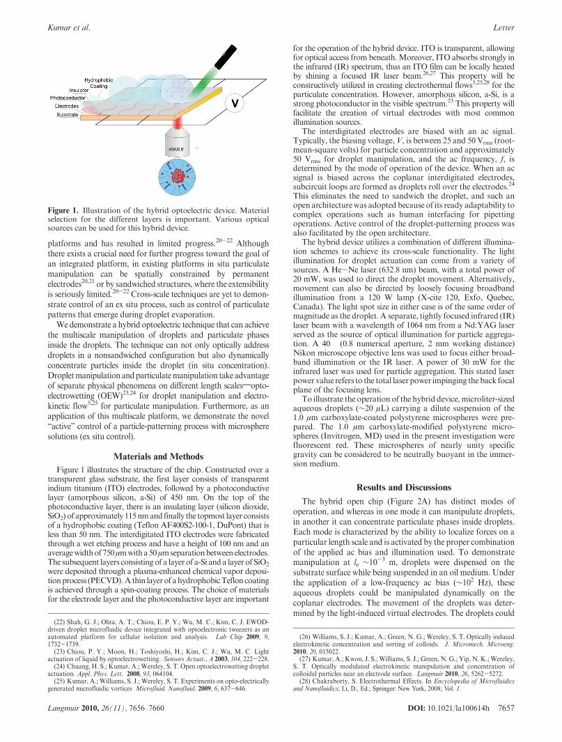
Figure 1 illustrates the structure of the chip. Constructed over atransparent glass substrate, the first layer consists of transparentindium titanium (ITO) electrodes, followed by a photoconductivelayer (amorphous silicon, a-Si) of 450 nm. On the top of thephotoconductive layer, there is an insulating layer (silicon dioxide,SiO2) of approximately115nmand finally the topmost layer consistsof a hydrophobic coating (Teflon AF400S2-100-1, DuPont) that isless than 50 nm. The interdigitated ITO electrodes were fabricatedthrough a wet etching process and have a height of 100 nm and anaveragewidthof750μmwitha50μmseparationbetweenelectrodes.The subsequent layers consistingof a layer of a-Si anda layer of SiO2
were deposited through a plasma-enhanced chemical vapor deposi-tionprocess (PECVD).A thin layerof ahydrophobicTefloncoatingis achieved through a spin-coating process. The choice of materialsfor the electrode layer and the photoconductive layer are important
for the operation of the hybrid device. ITO is transparent, allowingfor optical access from beneath.Moreover, ITO absorbs strongly inthe infrared (IR) spectrum, thus an ITO film can be locally heatedby shining a focused IR laser beam.26,27 This property will beconstructively utilized in creating electrothermal flows5,25,28 for theparticulate concentration. However, amorphous silicon, a-Si, is astrong photoconductor in the visible spectrum.23 This property willfacilitate the creation of virtual electrodes with most commonillumination sources.
The interdigitated electrodes are biased with an ac signal.Typically, the biasing voltage,V, is between 25 and 50 Vrms (root-mean-square volts) for particle concentration and approximately50 Vrms for droplet manipulation, and the ac frequency, f, isdetermined by the mode of operation of the device. When an acsignal is biased across the coplanar interdigitated electrodes,subcircuit loops are formed as droplets roll over the electrodes.24
This eliminates the need to sandwich the droplet, and such anopen architecturewas adopted because of its ready adaptability tocomplex operations such as human interfacing for pipettingoperations. Active control of the droplet-patterning process wasalso facilitated by the open architecture.
The hybrid device utilizes a combination of different illumina-tion schemes to achieve its cross-scale functionality. The lightillumination for droplet actuation can come from a variety ofsources. A He-Ne laser (632.8 nm) beam, with a total power of20 mW, was used to direct the droplet movement. Alternatively,movement can also be directed by loosely focusing broadbandillumination from a 120 W lamp (X-cite 120, Exfo, Quebec,Canada). The light spot size in either case is of the same order ofmagnitude as the droplet. A separate, tightly focused infrared (IR)laser beam with a wavelength of 1064 nm from a Nd:YAG laserserved as the source of optical illumination for particle aggrega-tion. A 40� (0.8 numerical aperture, 2 mm working distance)Nikon microscope objective lens was used to focus either broad-band illumination or the IR laser. A power of 30 mW for theinfrared laser was used for particle aggregation. This stated laserpower value refers to the total laserpower impinging the back focalplane of the focusing lens.
To illustrate the operation of the hybrid device,microliter-sizedaqueous droplets (∼20 μL) carrying a dilute suspension of the1.0 μm carboxylate-coated polystyrene microspheres were pre-pared. The 1.0 μm carboxylate-modified polystyrene micro-spheres (Invitrogen, MD) used in the present investigation werefluorescent red. These microspheres of nearly unity specificgravity can be considered to be neutrally buoyant in the immer-sion medium.
Results and Discussions
The hybrid open chip (Figure 2A) has distinct modes ofoperation, and whereas in one mode it can manipulate droplets,in another it can concentrate particulate phases inside droplets.Each mode is characterized by the ability to localize forces on aparticular length scale and is activated by the proper combinationof the applied ac bias and illumination used. To demonstratemanipulation at le ∼10-3 m, droplets were dispensed on thesubstrate surface while being suspended in an oil medium. Underthe application of a low-frequency ac bias (∼102 Hz), theseaqueous droplets could be manipulated dynamically on thecoplanar electrodes. The movement of the droplets was deter-mined by the light-induced virtual electrodes. The droplets could
Figure 1. Illustration of the hybrid optoelectric device. Materialselection for the different layers is important. Various opticalsources can be used for this hybrid device.
(22) Shah, G. J.; Ohta, A. T.; Chiou, E. P. Y.; Wu, M. C.; Kim, C. J. EWOD-driven droplet microfluidic device integrated with optoelectronic tweezers as anautomated platform for cellular isolation and analysis. Lab Chip 2009, 9,1732-1739.(23) Chiou, P. Y.; Moon, H.; Toshiyoshi, H.; Kim, C. J.; Wu, M. C. Light
actuation of liquid by optoelectrowetting. Sensors Actuat., A 2003, 104, 222-228.(24) Chuang, H. S.; Kumar, A.; Wereley, S. T. Open optoelectrowetting droplet
actuation. Appl. Phys. Lett. 2008, 93, 064104.(25) Kumar, A.; Williams, S. J.; Wereley, S. T. Experiments on opto-electrically
generated microfluidic vortices Microfluid. Nanofluid. 2009, 6, 637-646.
(26) Williams, S. J.; Kumar, A.; Green, N. G.; Wereley, S. T. Optically inducedelectrokinetic concentration and sorting of colloids. J. Micromech. Microeng.2010, 20, 015022.
(27) Kumar, A.; Kwon, J. S.; Williams, S. J.; Green, N. G.; Yip, N. K.; Wereley,S. T. Optically modulated electrokinetic manipulation and concentration ofcolloidal particles near an electrode surface. Langmuir 2010, 26, 5262-5272.
(28) Chakraborty, S. Electrothermal Effects. In Encyclopedia of Microfluidicsand Nanofluidics; Li, D., Ed.; Springer: New York, 2008; Vol. 1.

7658 DOI: 10.1021/la100614h Langmuir 2010, 26(11), 7656–7660
Letter Kumar et al.
be actuated by focusing broadband illumination from a 120 Wlamponto amillimeter-sized spot, as inFigure 2B-D; alternately,a millimeter-sized He-Ne laser beam with a total power of20 mW could also be used for droplet control. To localize forcesat le ≈ 10-6 m, a separate mode of operation is required. Thismode is activated through the use of a separate micrometer-sizedIR laser illumination spot and a higher-frequency ac bias(103-105 Hz). The localization of forces on such length scalesallowed the in situ manipulation of particulate phases inside thedroplet. For droplets placed directly on the electrode surface,particulate phases inside the droplets were concentrated on thewater-electrode interface by simultaneously focusing IR illumi-nation on the electrode surface and the application of theappropriate ac bias across the electrodes (Figure 2E,F andSupporting Information Movie 1). Concentration of the 1 μmpolystyrene particles (Figure 2G) results in massive particleaggregation around the illuminated region on the electrode sur-face. Deactivating the IR laser resulted in the immediate disper-sion of the aggregated particles (Figure 2F, SupportingInformation Movie 1). Particle transport in the device is rapid
and can be faster than achieved with many other optical techni-ques.29 A translation of the laser focal point results in a con-sequent translation of the vortex center, and hence particleaggregation in this hybrid device is dynamic in nature (Support-ing Information Movie 1). When the aqueous droplets weresuspended in a silicone oil medium, the particulate phases couldbe concentrated on the water-oil interface (data not shown).
Cross-scale manipulation in this hybrid device constructivelyutilizes many different phenomena. The guiding principle ofdroplet manipulation is OEW. Virtual electrodes are created bythe locally illuminated photoconductive layer, and for an equi-valent circuit analysis, see ref 24. Employing a photoconductivelayer enables arbitrarily controllable droplet movement inducedby a light source. The photoconductor here serves as a binarygate, which establishes a local circuit loop that is closed whenilluminated and is openwhen dark (Figure 3A). Previous researchshows that the optimal range of the driving frequency is between100 and 800 Hz.24
In situ particle manipulation requires a separate operationmode of the device. In this mode, a higher ac frequency is usedalong with highly focused IR illumination (Figure 3B). Ascompared to the low ac frequencies (<1 kHz) used for droplet
Figure 2. Cross-scale capabilities of the hybrid device. (A) Theactual chip used in our experiments. (B-D)A20μLdropletmovesfrom its initial position (shown by the dashed circle) toward anilluminated site on the chip. The illumination is provided through amicroscope objective lens with focused broadband light. Theapplied ac biasing conditions were V = 50 Vrms and f = 300 Hz.(E) Massive aggregation of 1 μm polystyrene particles around anIR-illuminated site at the water-electrode interface. The appliedac biasing conditions were V = 28 Vrms and f= 25 kHz. (F) Theparticle group disperses when the IR illumination is deactivated.(G) Particle aggregation consists of thousands of loosely packed1 μm particles, which are stacked into several layers.
Figure 3. (A) For dropletmotion, virtual electrodes are created byutilizing the photoconductive nature of a-Si. The typical illumina-tion used lies in the visible spectrum, and the spot size is approxi-mately the same size as the droplet. Virtual electrodes aredetermined by the illuminated site through a shift in the principalvoltage drop.24 The terms Ci, Cw, and Cph are the capacitances ofthe insulator, the droplet, and the photoconductor, respectively;Rw and Rph are the resistances of the droplet and the photocon-ductor, respectively. (B) Illustration of the mechanism of theparticle concentration inside the droplet. An IR laser is focusedonto a spot through a microscope objective lens, and suspendedparticles are transported to the IR-illuminated region. The bluearrows indicate the direction of electrothermal flow. Ac electro-osmosis also contributes to fluid flow (indicatedbyorange arrows).The transported particles are trapped on the electrode surface bythe concerted action of different electrokinetic mechanisms.
(29) Hayward, R. C.; Saville, D. A.; Aksay, I. A. Electrophoretic assembly ofcolloidal crystals with optically tunable micropatterns. Nature 2000, 404, 56-59.
DOI: 10.1021/la100614h 7659Langmuir 2010, 26(11), 7656–7660
Kumar et al. Letter
actuation, switching to a higher ac frequency (>1 kHz) estab-lishes an electric field inside the droplet. This allows for in situparticle concentration by taking advantage of multiple electro-kinetic phenomena. First, intense illumination at 1064 nm(∼106W/cm2) can cause localized heating of the ITO substrate,27
resulting in gradients of temperature and consequently in theelectrical conductivity (σ) and permittivity (ε) of the fluid.Gradients in electrical conductivity and electrical permittivity ofthe fluid in the presence of electric fields can generate electro-thermal microvortices.25 Second, ac electroosmotic (ACEO)flows are generated by electrode polarization in a nonuniformac electric field.30-32 For an interdigitated electrode configurationsuch as ours, the ACEO flow is transverse to the electrodestructure. For a droplet dispensed directly onto the electrodesubstrate, particle transport to an IR-illuminated region at thewater-electrode interface (Figure 2E) is caused by a combinationof a toroidal electrothermal microvortex and transverse ACEOflow (Figure 3B). The resultant fluid flow transports particlestoward the focal point of the IR laser, where particles arenonpermanently polarized and captured at the center of thevortex at the water-electrode interface because of low-frequencyac electrokinetics.33 Even though such particle aggregation inthis optoelectric platform constructively exploits many diff-erent electrokinetic phenomena, thermally induced electrother-mal flow plays a dominant role in the process. This was easilydemonstrated because deactivating the IR laser causes the particlegroup to disperse (Supporting Information Movie 1). Particle
aggregation, activated by IR illumination, was also noticed at thewater-oil interface when the dispensed droplet was immersed inan oil medium. Such aggregation at the water-oil interface is notfully understood and needs further investigation. A partiallysimilar mode of in situ particle concentration for a continuousmicrofluidic system was demonstrated recently by Williamset al.33 Despite some progress,26,27 a comprehensive modelingof the forces present in their system is yet to be achieved.Althoughthose forces are definitely also present in our system, a completeunderstanding of the particle-concentration process is exacer-bated by the numerous additional effects that are present.
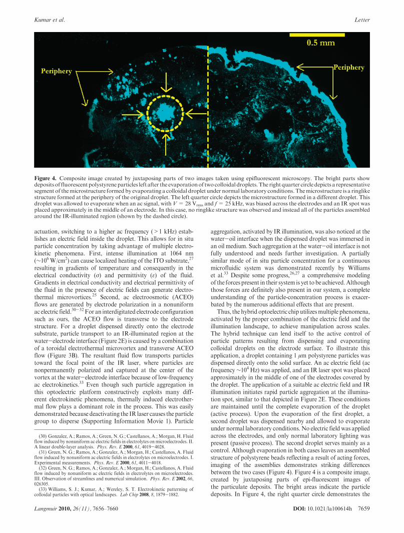
Thus, the hybrid optoelectric chip utilizesmultiple phenomena,activated by the proper combination of the electric field and theillumination landscape, to achieve manipulation across scales.The hybrid technique can lend itself to the active control ofparticle patterns resulting from dispensing and evaporatingcolloidal droplets on the electrode surface. To illustrate thisapplication, a droplet containing 1 μm polystyrene particles wasdispensed directly onto the solid surface. An ac electric field (acfrequency∼104 Hz) was applied, and an IR laser spot was placedapproximately in the middle of one of the electrodes covered bythe droplet. The application of a suitable ac electric field and IRillumination initiates rapid particle aggregation at the illumina-tion spot, similar to that depicted in Figure 2E. These conditionsare maintained until the complete evaporation of the droplet(active process). Upon the evaporation of the first droplet, asecond droplet was dispensed nearby and allowed to evaporateunder normal laboratory conditions. No electric field was appliedacross the electrodes, and only normal laboratory lighting waspresent (passive process). The second droplet serves mainly as acontrol. Although evaporation in both cases leaves an assembledstructure of polystyrene beads reflecting a result of acting forces,imaging of the assemblies demonstrates striking differencesbetween the two cases (Figure 4). Figure 4 is a composite image,created by juxtaposing parts of epi-fluorescent images ofthe particulate deposits. The bright areas indicate the particledeposits. In Figure 4, the right quarter circle demonstrates the
Figure 4. Composite image created by juxtaposing parts of two images taken using epifluorescent microscopy. The bright parts showdepositsof fluorescent polystyreneparticles left after the evaporationof twocolloidal droplets. The right quarter circledepicts a representativesegment of themicrostructure formedby evaporating a colloidal droplet under normal laboratory conditions. Themicrostructure is a ringlikestructure formed at the periphery of the original droplet. The left quarter circle depicts the microstructure formed in a different droplet. Thisdroplet was allowed to evaporate when an ac signal, withV=28 Vrms and f=25 kHz, was biased across the electrodes and an IR spot wasplaced approximately in the middle of an electrode. In this case, no ringlike structure was observed and instead all of the particles assembledaround the IR-illuminated region (shown by the dashed circle).
(30) Gonzalez, A.; Ramos, A.; Green, N. G.; Castellanos, A.; Morgan, H. Fluidflow induced by nonuniform ac electric fields in electrolytes onmicroelectrodes. II.A linear double-layer analysis. Phys. Rev. E 2000, 61, 4019-4028.(31) Green, N. G.; Ramos, A.; Gonzalez, A.; Morgan, H.; Castellanos, A. Fluid
flow induced by nonuniform ac electric fields in electrolytes on microelectrodes. I.Experimental measurements. Phys. Rev. E 2000, 61, 4011-4018.(32) Green, N. G.; Ramos, A.; Gonzalez, A.; Morgan, H.; Castellanos, A. Fluid
flow induced by nonuniform ac electric fields in electrolytes on microelectrodes.III. Observation of streamlines and numerical simulation. Phys. Rev. E 2002, 66,026305.(33) Williams, S. J.; Kumar, A.; Wereley, S. T. Electrokinetic patterning of
colloidal particles with optical landscapes. Lab Chip 2008, 8, 1879-1882.
7660 DOI: 10.1021/la100614h Langmuir 2010, 26(11), 7656–7660
Letter Kumar et al.
microstructure formed by the passive process, where a ringlikestructure is formed by the aggregation of the particulates at thedroplet periphery. Such a ringlike structure is an assembly formedcommonly by a passive evaporation process.14 The left quartercircle in Figure 4 shows that particle deposition for the activeprocess is almost exclusively concentrated at the locationof the IRspot. Electrokinetic flow, as depicted inFigure 2E,F and Support-ing Information Movie 1, thus alters the assembly processresulting from the droplet drying process. To confirm the roleof electrokinetic flow, experiments were also conducted in theabsence of electric fields and with the sole application of an IRbeam.Although the sole application of IR illumination could alsoresult in some localized deposits, such deposits were found to befar less pronounced (Supporting Information Figure S1).
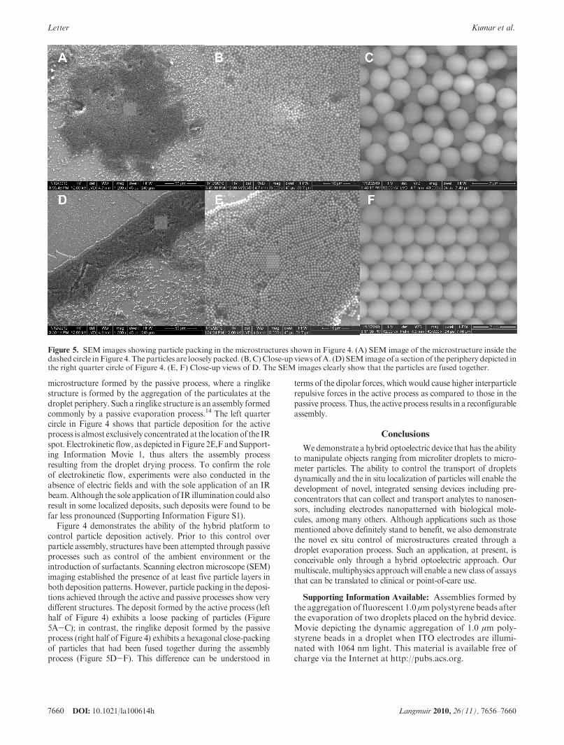
Figure 4 demonstrates the ability of the hybrid platform tocontrol particle deposition actively. Prior to this control overparticle assembly, structures have been attempted through passiveprocesses such as control of the ambient environment or theintroduction of surfactants. Scanning electron microscope (SEM)imaging established the presence of at least five particle layers inboth deposition patterns.However, particle packing in the deposi-tions achieved through the active and passive processes show verydifferent structures. The deposit formed by the active process (lefthalf of Figure 4) exhibits a loose packing of particles (Figure5A-C); in contrast, the ringlike deposit formed by the passiveprocess (right half of Figure 4) exhibits a hexagonal close-packingof particles that had been fused together during the assemblyprocess (Figure 5D-F). This difference can be understood in
terms of the dipolar forces, which would cause higher interparticlerepulsive forces in the active process as compared to those in thepassive process. Thus, the active process results in a reconfigurableassembly.
Conclusions
Wedemonstrate a hybrid optoelectric device that has the abilityto manipulate objects ranging from microliter droplets to micro-meter particles. The ability to control the transport of dropletsdynamically and the in situ localization of particles will enable thedevelopment of novel, integrated sensing devices including pre-concentrators that can collect and transport analytes to nanosen-sors, including electrodes nanopatterned with biological mole-cules, among many others. Although applications such as thosementioned above definitely stand to benefit, we also demonstratethe novel ex situ control of microstructures created through adroplet evaporation process. Such an application, at present, isconceivable only through a hybrid optoelectric approach. Ourmultiscale,multiphysics approachwill enable a new class of assaysthat can be translated to clinical or point-of-care use.
Supporting Information Available: Assemblies formed bythe aggregation of fluorescent 1.0 μmpolystyrene beads afterthe evaporation of two droplets placed on the hybrid device.Movie depicting the dynamic aggregation of 1.0 μm poly-styrene beads in a droplet when ITO electrodes are illumi-nated with 1064 nm light. This material is available free ofcharge via the Internet at http://pubs.acs.org.
Figure 5. SEM images showing particle packing in the microstructures shown in Figure 4. (A) SEM image of the microstructure inside thedashed circle inFigure 4.The particles are loosely packed. (B,C) Close-up views ofA. (D) SEM image of a section of the periphery depicted inthe right quarter circle of Figure 4. (E, F) Close-up views of D. The SEM images clearly show that the particles are fused together.