Dynamic fracture of berylium-bearing bulk metallic glass...
15
Dynamic fracture of berylium-bearing bulk metallic glass systems: A cross-technique comparison D. Rittel a, * , A.J. Rosakis b a Faculty of Mechanical Engineering, Technion, Israel Institute of Technology, Technion City, 32000 Haifa, Israel b Graduate Aeronautical Laboratories, California Institute of Technology, Pasadena, CA 91125, USA Received 31 August 2004; received in revised form 19 October 2004; accepted 19 October 2004 Available online 3 March 2005 Abstract We report on a detailed comparison between two different experimental techniques used to measure the dynamic initiation fracture toughness K d IC of a bulk metallic glass system (Vitreloy-1) and its b-phase composite. Both the coher- ent gradient sensing interferometry (CGS) and one-point impact techniques reveal very similar trends in the K d IC – _ K d I relationship for Vitreloy-1. A drastic increase in initiation toughness with the stress intensity rate is observed. By con- trast, the one-point impact method shows a relative rate-insensitivity for the K d IC of the b-phase composite. The results are rationalized through a detailed characterization of the failure mechanisms. Ó 2005 Elsevier Ltd. All rights reserved. Keywords: Bulk metallic glass; Coherent gradient sensing; One-point impact; Dynamic fracture; Adiabatic shear banding 1. Introduction The earliest studies on the mechanical properties of metallic glasses revealed their extraordinary charac- teristics, most notably their relatively high strength and low elastic moduli [1]. However, until recently these alloys could only be fabricated as thin sheets or rods with diameters of less than 2 mm, thereby limiting the extent of detailed experimental characterization of their mechanical properties using conventional testing techniques. The development of bulk metallic glasses by Inoue and co-workers [2,3] and Peker and Johnson [4] has heightened interest in this class of materials for a variety of engineering applications. Furthermore, the larger ingot sizes have facilitated the study of abroad range of material properties. 0013-7944/$ - see front matter Ó 2005 Elsevier Ltd. All rights reserved. doi:10.1016/j.engfracmech.2004.10.015 * Corresponding author. Tel.: +972 4829 3261; fax: +972 4832 4533. E-mail address: [email protected] (D. Rittel). Engineering Fracture Mechanics 72 (2005) 1905–1919 www.elsevier.com/locate/engfracmech
Transcript of Dynamic fracture of berylium-bearing bulk metallic glass...
Engineering Fracture Mechanics 72 (2005) 1905–1919
www.elsevier.com/locate/engfracmech
Dynamic fracture of berylium-bearing bulk metallicglass systems: A cross-technique comparison
D. Rittel a,*, A.J. Rosakis b
a Faculty of Mechanical Engineering, Technion, Israel Institute of Technology, Technion City, 32000 Haifa, Israelb Graduate Aeronautical Laboratories, California Institute of Technology, Pasadena, CA 91125, USA
Received 31 August 2004; received in revised form 19 October 2004; accepted 19 October 2004
Available online 3 March 2005
Abstract
We report on a detailed comparison between two different experimental techniques used to measure the dynamic
initiation fracture toughness KdIC of a bulk metallic glass system (Vitreloy-1) and its b-phase composite. Both the coher-
ent gradient sensing interferometry (CGS) and one-point impact techniques reveal very similar trends in the KdIC–
_Kd
I
relationship for Vitreloy-1. A drastic increase in initiation toughness with the stress intensity rate is observed. By con-
trast, the one-point impact method shows a relative rate-insensitivity for the KdIC of the b-phase composite. The results
are rationalized through a detailed characterization of the failure mechanisms.
� 2005 Elsevier Ltd. All rights reserved.
Keywords: Bulk metallic glass; Coherent gradient sensing; One-point impact; Dynamic fracture; Adiabatic shear banding
1. Introduction
The earliest studies on the mechanical properties of metallic glasses revealed their extraordinary charac-
teristics, most notably their relatively high strength and low elastic moduli [1]. However, until recently these
alloys could only be fabricated as thin sheets or rods with diameters of less than 2 mm, thereby limiting theextent of detailed experimental characterization of their mechanical properties using conventional testing
techniques. The development of bulk metallic glasses by Inoue and co-workers [2,3] and Peker and Johnson
[4] has heightened interest in this class of materials for a variety of engineering applications. Furthermore,
the larger ingot sizes have facilitated the study of abroad range of material properties.
0013-7944/$ - see front matter � 2005 Elsevier Ltd. All rights reserved.
doi:10.1016/j.engfracmech.2004.10.015
* Corresponding author. Tel.: +972 4829 3261; fax: +972 4832 4533.
E-mail address: [email protected] (D. Rittel).
1906 D. Rittel, A.J. Rosakis / Engineering Fracture Mechanics 72 (2005) 1905–1919
Although several compositions of bulk metallic glasses have successfully been processed, one of the more
promising and widely studied alloys is Zr41.25Ti13.75Ni10Cu12.75Be22.5, also known by its commercial name,
Vitreloy-1. Studies of the dynamic constitutive response of this alloy by Rosakis, Johnson and their re-
search group have demonstrated elastic–perfectly plastic behavior with a strain-rate independent tensile/
compressive flow stress of approximately 2 GPa [5,6]. Failure in these specimens occurs in a highly unstablemanner along planes inclined by 45� with respect to the loading axis as a result of shear localization. Using
high-speed infrared diagnostics Bruck et al. [6] observed that the temperatures accompanying localized
shear failure due to adiabatic heating approach 775 K, more than 80% of the melting temperature.
Direct measurement of the static mode-I fracture toughness, KIC of Vitreloy-1 has been made by Conner
et al. [7] and Gilbert et al. [8] with KIC of the order of 55 MPa m1/2, a value similar to the toughness of typ-
ical high strength polycrystalline metallic alloys. However, in contrast to many steels, aluminum alloys and
titanium alloys, the onset of failure is followed by highly unstable, dynamic crack propagation. A dramatic
reduction in toughness has been reported when a significant fraction of crystalline phases are introducedthrough heating treatment [8,9], resulting in materials with KIC � 2 MPa m1/2. Also Lowhaphandu and
Lewandowski [10] have observed a value of KIC � 20 MPa m1/2 on a nominally amorphous material of sim-
ilar, but not of a composition identical to Vitreloy-1. It was suggested that this apparently lower toughness
might have resulted from differences in specimen geometry or preparation or slight variations in
composition.
In the studies on bulk metallic glasses cited above, dynamically propagating cracks or shear bands have
been reported to occur consistently under either quasi-static or dynamic loading conditions. Although such
observations have never been studied systematically thus far, these early reports indicate the importance ofdeveloping a detailed understanding of dynamic failure mechanisms in bulk metallic glasses, as well as of
the transitions in failure behavior from tensile cracking to shear banding. One of the important parameters
is the dynamic crack initiation toughness ðKdICÞ of these materials and its dependence on the loading rate
ð _Kd
I Þ.As of today, there is no standardized method to measure the dynamic initiation toughness of materials,
and various methods have been suggested. Among these, the coherent gradient sensing method (CGS) is an
optical method that has been devised by Rosakis [11] to obtain a full-field characterization of the crack-tip
subjected to transient loading. The CGS, described in the sequel, provides a full characterization of thecrack-tip throughout its history, including initiation, propagation and arrest phases. However, the method
necessitates sophisticated equipment, for both optical and imaging purposes, including a costly high-speed
camera with typical framing rates in excess of 1 Mfps. On the other hand, a very simple hybrid experimen-
tal–numerical approach has been devised by Weisbrod and Rittel, based on one-point impact technique
[12].These techniques will subsequently be referred to as ‘‘Caltech’’ and ‘‘Technion’’ techniques respec-
tively. To the best of the authors� knowledge, systematic comparisons between methods to characterize
the dynamic initiation toughness have not been carried out, while such comparisons would be highly useful
to the experimentalists and practicing engineers.Consequently, the purpose of the present paper is twofold. First, two radically different methods of
determination of KdIC are systematically compared, and as will be shown, yield identical results. The second
central point of this paper is a general investigation of the dynamic initiation toughness and failure mech-
anisms of two grades of bulk metallic glasses, one basic and one composite. The paper is organized as fol-
lows: first, each experimental approach is described and it may be noted that the two approaches are
radically different. Next, experimental results are shown for the basic BMG (Vitreloy-1), showing that iden-
tical KdIC–
_Kd
I trends are observed using each method. Both notch and fatigue precracked specimens are
investigated and their failure mechanisms characterized. The following section reports similar results forthe b-composite BMG, using the one-point impact technique [12]. The discussion section evaluates the re-
sults and establishes a comparison between the two investigated grades of BMG. The final section brings
concluding remarks.
D. Rittel, A.J. Rosakis / Engineering Fracture Mechanics 72 (2005) 1905–1919 1907
2. Experimental
2.1. Materials
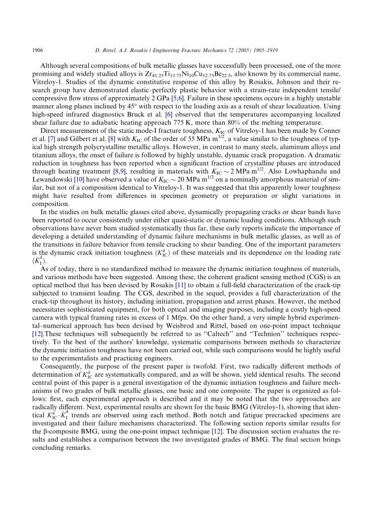
Plate specimens of (w/o) Zr41.25Ti13.75Ni10Cu12.75Be22.5 (Vitreloy-1) were provided by Amorphous Tech-nologies International, Inc. Two different batches of material were supplied that were fabricated using vary-
ing processing parameters, the details of which are proprietary. The two batches will be designated as Lots
41 and 46, respectively. The nominal dimensions of the as-received plates were 75 · 150 · 4 mm. These large
plate specimens were used for the dynamic fracture experiments described below. A b-phase Vitreloy-1
composite (b-composite) of (w/o) Zr56.2Ti13.80Nb5.0Cu6.90Ni5.60Be12.5 was also supplied for investigation
as small beam specimens. For each material, the dilatational and shear wave speeds of the two different
materials were measured. The wave speeds, along with the measured densities were used to calculate the
elastic constants of the material, as shown in Table 1.
2.2. Caltech technique
A limited number of plates were cut into smaller specimens having planar dimensions of 25 · 50 mm for
fracture testing under quasi-static conditions which are also described below. A wire EDM notch was fab-
ricated into the center of the longest side of the specimen, having a depth of approximately one-third of the
specimen width. A fatigue crack was grown from the end of the notch using Kmin = 4 MPa m1/2 and
Kmax = 8 MPa m1/2 at a frequency of 10 Hz. The extension of the fatigue crack from the end of the notchwas approximately 1 mm for the smaller specimens and 2 mm for the larger specimens. The specimens were
lapped and polished to provide a flat and specularly reflective surface for optical interferometry resulting in
final specimen thicknesses of 3.2 ± 0.1 mm.
In the quasi-static range, _Kd
I < 104 MPa m1/2 s�1, the fracture experiments were conducted in a three-
point bend configuration using a hydraulic Materials Testing System. The displacement rate was varied sys-
tematically, yielding a broad range of loading rates. The time history of the stress intensity factor KdI ðtÞ was
calculated directly from the time varying load and the specimen geometry. The fracture toughness was
taken as the peak value of KdI ðtÞ, whereas the quasi-static loading rate was determined from the slope of
the KdI ðtÞ versus time curve, expressed as _K
d
I .
In the dynamic range, _Kd
I P 104 MPa m1/2 s�1, a different loading configuration and diagnostic methods
were used. A schematic illustration of the experimental configuration for these experiments is shown in Fig.
1. A Dynatup drop weight tower was used to load specimens in dynamic three-point bend at impact veloc-
ities ranging from 1 to 6 m/s. The mechanical fields in the vicinity of the dynamically loaded crack tip were
recorded using a Cordin 330 high-speed camera in conjunction with optical interferometry. The interfero-
metric technique employed was coherent gradient sensing (CGS) which has been described in great detail
Table 1
Physical and mechanical properties of the investigated materials
Vitreloy-1 b-Composite
Cpl�el (m/s) 5194 4576
Cpl�rl (m/s) 4294 3813
Cs (m/s) 2429 2133
q (kg/m3) 6147 6391
E (GPa) 98.7 79.9
l (GPa) 36.3 29.1
m 0.360 0.374
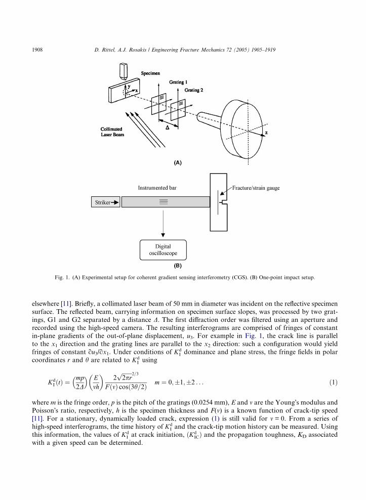
Fig. 1. (A) Experimental setup for coherent gradient sensing interferometry (CGS). (B) One-point impact setup.
1908 D. Rittel, A.J. Rosakis / Engineering Fracture Mechanics 72 (2005) 1905–1919
elsewhere [11]. Briefly, a collimated laser beam of 50 mm in diameter was incident on the reflective specimen
surface. The reflected beam, carrying information on specimen surface slopes, was processed by two grat-
ings, G1 and G2 separated by a distance D. The first diffraction order was filtered using an aperture andrecorded using the high-speed camera. The resulting interferograms are comprised of fringes of constant
in-plane gradients of the out-of-plane displacement, u3. For example in Fig. 1, the crack line is parallel
to the x1 direction and the grating lines are parallel to the x2 direction: such a configuration would yield
fringes of constant ou3/ox1. Under conditions of KdI dominance and plane stress, the fringe fields in polar
coordinates r and h are related to KdI using
KdI ðtÞ ¼
mp2D
� � Emh
� �2
ffiffiffiffiffiffiffi2pr
p 2=3
F ðmÞ cosð3h=2Þ m ¼ 0;�1;�2 . . . ð1Þ
where m is the fringe order, p is the pitch of the gratings (0.0254 mm), E and m are the Young�s modulus and
Poisson�s ratio, respectively, h is the specimen thickness and F(m) is a known function of crack-tip speed
[11]. For a stationary, dynamically loaded crack, expression (1) is still valid for m = 0. From a series of
high-speed interferograms, the time history of KdI and the crack-tip motion history can be measured. Using
this information, the values of KdI at crack initiation, ðKd
ICÞ and the propagation toughness, KD associated
with a given speed can be determined.
D. Rittel, A.J. Rosakis / Engineering Fracture Mechanics 72 (2005) 1905–1919 1909
2.3. Technion technique
Short beam specimens were used, that contained two types of cracks, dividing the specimens into two
equal groups: a 0.2 mm root radius notch (notched specimens), introduced either by electro-discharge
machining, or using a diamond wafering blade. The other kind of specimen was fatigue precracked in threepoint bending (cracked specimens), using a procedure similar to that of the Caltech group. Small beam
specimens, with the following dimensions were used: for the base BMG, the beam was typically 25 mm
long, 4.8 mm thick and 6.1 mm high. A typical crack/notch length was 2.1 mm. For the b-composite, the
beam specimen was typically 25.4 mm long, 3.0 mm thick and 10.16 mm high. A typical crack/notch length
was 5 mm.
The quasi-static fracture toughness, KIC, was measured in three-point bending, using an MTS 810, com-
puter controlled servo-hydraulic testing machine. The stress intensity factor was calculated using a finite
element model of the specimen, with an applied unit load of 1 N. For all tests, the load was observed toincrease linearly until final abrupt fracture. Consequently, the fracture toughness was calculated by multi-
plying the unit SIF by the fracture load.
Based on linear elastic fracture mechanics assumptions, the transient stress intensity factor (SIF) result-
ing from unit impulse loading, k̂d
I ðtÞ, can be calculated numerically or analytically for any cracked structure,
as long as the crack remains stationary. Consequently, if the boundary conditions and applied loads P(t)
are well defined, the resulting stress intensity factor is given by
KdI ðtÞ ¼ P ðtÞ � k̂dI ðtÞ ð2Þ
Denoting the fracture time by tfrac, the initiation toughness is the value of the SIF at fracture,
KdIC ¼ Kd
I ðt ¼ tfracÞ ð3Þ
This approach has been validated experimentally by Weisbrod and Rittel [12] using short beam specimens.These authors showed that measured crack-tip SIF�s were in excellent agreement with SIF�s calculated
using Eq. (2). Estimation of the dynamic initiation toughness was based on Eqs. (2) and (3). The specimen
was instrumented on each side with short single wire fracture gauges, whose reliability has been assessed by
Weisbrod and Rittel [12], and also by Rittel and Weisbrod [13].
3. Results
3.1. Base BMG (Vitreloy-1)
The KIC values measured by the Caltech group were typically KIC � 50 MPa m1/2 on precracked speci-
mens. For the notched and precracked specimen, a value of KIC � 56.6�77.6 MPa m1/2 was measured at
Technion, without apparent difference between the two groups. A total of two precracked and two notched
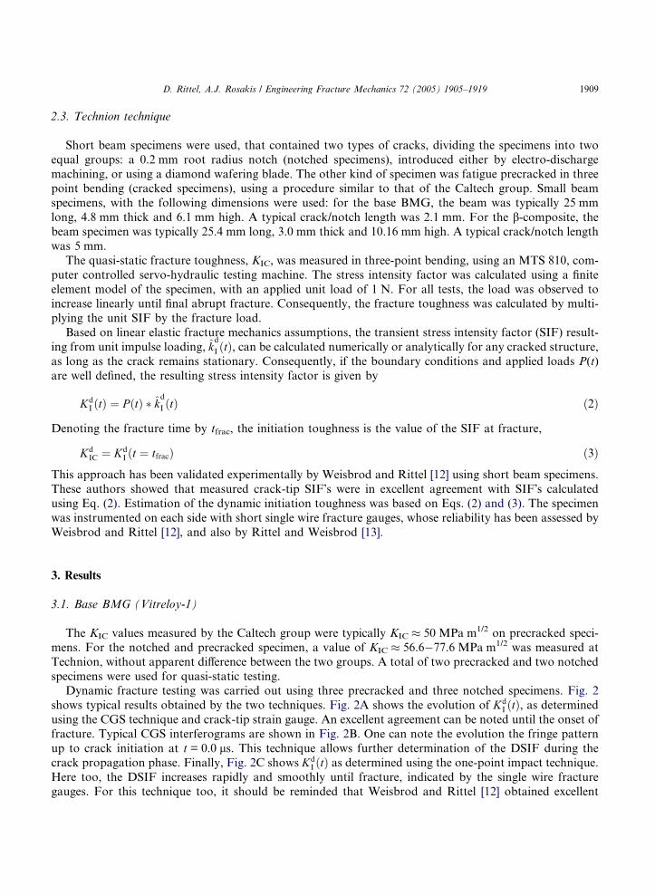
specimens were used for quasi-static testing.Dynamic fracture testing was carried out using three precracked and three notched specimens. Fig. 2
shows typical results obtained by the two techniques. Fig. 2A shows the evolution of KdI ðtÞ, as determined
using the CGS technique and crack-tip strain gauge. An excellent agreement can be noted until the onset of
fracture. Typical CGS interferograms are shown in Fig. 2B. One can note the evolution the fringe pattern
up to crack initiation at t = 0.0 ls. This technique allows further determination of the DSIF during the
crack propagation phase. Finally, Fig. 2C shows KdI ðtÞ as determined using the one-point impact technique.
Here too, the DSIF increases rapidly and smoothly until fracture, indicated by the single wire fracture
gauges. For this technique too, it should be reminded that Weisbrod and Rittel [12] obtained excellent
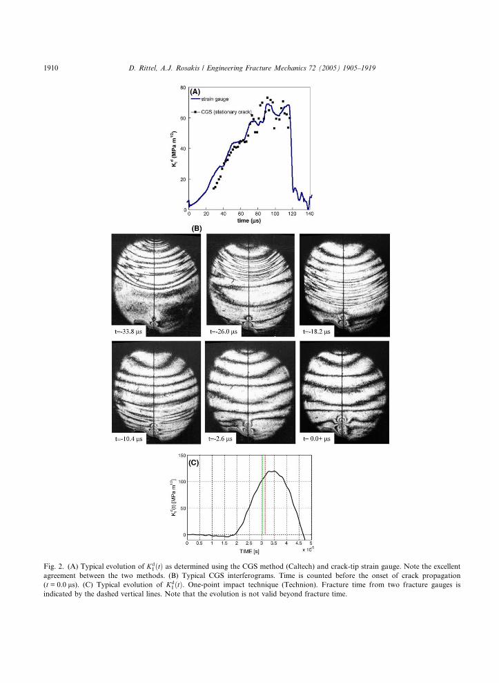
Fig. 2. (A) Typical evolution of KdI ðtÞ as determined using the CGS method (Caltech) and crack-tip strain gauge. Note the excellent
agreement between the two methods. (B) Typical CGS interferograms. Time is counted before the onset of crack propagation
(t = 0.0 ls). (C) Typical evolution of KdI ðtÞ. One-point impact technique (Technion). Fracture time from two fracture gauges is
indicated by the dashed vertical lines. Note that the evolution is not valid beyond fracture time.
1910 D. Rittel, A.J. Rosakis / Engineering Fracture Mechanics 72 (2005) 1905–1919
D. Rittel, A.J. Rosakis / Engineering Fracture Mechanics 72 (2005) 1905–1919 1911
agreement with crack-tip strain gauges. The values of the high-rate initiation toughness measured by each
group are summarized in Table 2. Fig. 3 summarizes the KdIC–
_Kd
I relationship for the precracked specimens,
as determined from each method. A striking similarity of the results obtained by each method is first of all
noticeable. Fig. 3 also shows an identical trend for a dramatic increase in the initiation toughness with the
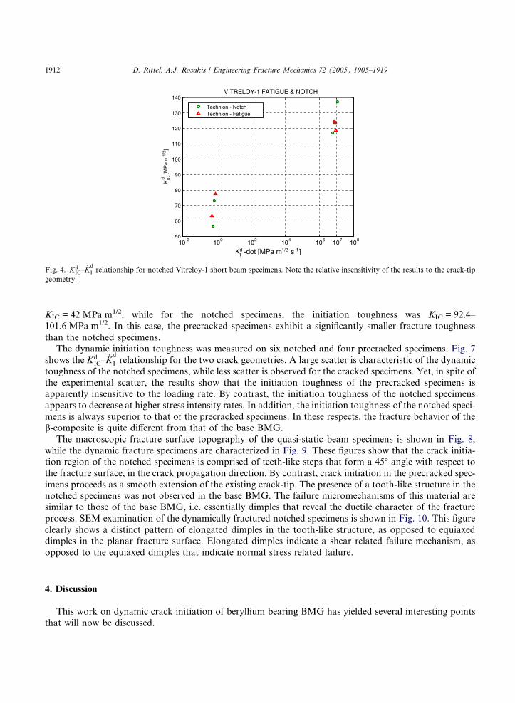
loading rate. Fig. 4 summarizes the results obtained for notched and precracked specimens together, astested using the short beam technique. This figure shows that the specific notches used in this work do nei-
ther influence the value of the initiation toughness nor its rate sensitivity.
Typical fracture surface morphology of quasi-statically loaded specimens is shown in Fig. 5, and of
dynamically loaded specimens is shown in Fig. 6. The two main failure mechanisms are dimples and some
flat cleavage-like facets. The fractographic analysis did not disclose a significant difference between the two
kinds of specimens. An important point is that in all the cases, the fracture surface is essentially planar, as
an extension of the fracture origin.
3.2. b-Phase composite BMG (b-phase-Vitreloy-1)
This alloy was investigated by the Technion group only. The static fracture toughness was deter-
mined from three notched and one precracked specimens. For the precracked specimen, a value of
Table 2
High rate initiation toughness values measured by the two groups
Laboratory _Kd
I (MPa m1/2 s�1) KdIC (MPa m1/2)
Caltech 2.62 · 106 179
’’ 5.41 · 106 160
’’ 5.55 · 106 286
Technion 7.41 · 106 124
Caltech 8.18 · 106 216
Technion 8.87 · 106 124
’’ 9.00 · 106 118
10-3 10-2 10-1 100 101 102 103 104 106 1080
50
100
150
200
250
300
K -dot [MPa m1/2 s-1]
KIC
[MP
a m
1/2 ]
Lot 41-RosakisLot 46-RosakisTechnion Fatigue
VITRELOY-1
d
I
d
Fig. 3. KdIC–
_Kd
I relationship for precracked Vitreloy-1 specimens. Results obtained using the two characterization methods.
10-2 100 102 104 106 107 10850
60
70
80
90
100
110
120
130
140
KId -dot [MPa m1/2 s-1]
K
[M
Pa.
m1/
2 ]
VITRELOY-1 FATIGUE & NOTCH
Technion - NotchTechnion - Fatigue
ICd
Fig. 4. KdIC–
_Kd
I relationship for notched Vitreloy-1 short beam specimens. Note the relative insensitivity of the results to the crack-tip
geometry.
1912 D. Rittel, A.J. Rosakis / Engineering Fracture Mechanics 72 (2005) 1905–1919
KIC = 42 MPa m1/2, while for the notched specimens, the initiation toughness was KIC = 92.4–
101.6 MPa m1/2. In this case, the precracked specimens exhibit a significantly smaller fracture toughness
than the notched specimens.
The dynamic initiation toughness was measured on six notched and four precracked specimens. Fig. 7
shows the KdIC–
_Kd
I relationship for the two crack geometries. A large scatter is characteristic of the dynamic
toughness of the notched specimens, while less scatter is observed for the cracked specimens. Yet, in spite of
the experimental scatter, the results show that the initiation toughness of the precracked specimens is
apparently insensitive to the loading rate. By contrast, the initiation toughness of the notched specimensappears to decrease at higher stress intensity rates. In addition, the initiation toughness of the notched speci-
mens is always superior to that of the precracked specimens. In these respects, the fracture behavior of the
b-composite is quite different from that of the base BMG.
The macroscopic fracture surface topography of the quasi-static beam specimens is shown in Fig. 8,
while the dynamic fracture specimens are characterized in Fig. 9. These figures show that the crack initia-
tion region of the notched specimens is comprised of teeth-like steps that form a 45� angle with respect to
the fracture surface, in the crack propagation direction. By contrast, crack initiation in the precracked spec-
imens proceeds as a smooth extension of the existing crack-tip. The presence of a tooth-like structure in thenotched specimens was not observed in the base BMG. The failure micromechanisms of this material are
similar to those of the base BMG, i.e. essentially dimples that reveal the ductile character of the fracture
process. SEM examination of the dynamically fractured notched specimens is shown in Fig. 10. This figure
clearly shows a distinct pattern of elongated dimples in the tooth-like structure, as opposed to equiaxed
dimples in the planar fracture surface. Elongated dimples indicate a shear related failure mechanism, as
opposed to the equiaxed dimples that indicate normal stress related failure.
4. Discussion
This work on dynamic crack initiation of beryllium bearing BMG has yielded several interesting points
that will now be discussed.
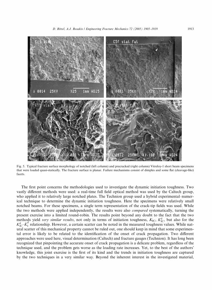
Fig. 5. Typical fracture surface morphology of notched (left column) and precracked (right column) Vitreloy-1 short beam specimens
that were loaded quasi-statically. The fracture surface is planar. Failure mechanisms consist of dimples and some flat (cleavage-like)
facets.
D. Rittel, A.J. Rosakis / Engineering Fracture Mechanics 72 (2005) 1905–1919 1913
The first point concerns the methodologies used to investigate the dynamic initiation toughness. Two
vastly different methods were used: a real-time full field optical method was used by the Caltech group,
who applied it to relatively large notched plates. The Technion group used a hybrid experimental–numer-
ical technique to determine the dynamic initiation toughness. Here the specimens were relatively small
notched beams. For these specimens, a single term representation of the crack-tip fields was used. While
the two methods were applied independently, the results were also compared systematically, turning the
present exercise into a limited round-robin. The results point beyond any doubt to the fact that the twomethods yield very similar results, not only in terms of initiation toughness, KIC, K
dIC, but also for the
KdIC–
_Kd
I relationship. However, a certain scatter can be noted in the measured toughness values. While nat-
ural scatter of this mechanical property cannot be ruled out, one should keep in mind that some experimen-
tal error is likely to be related to the identification of the onset of crack propagation. Two different
approaches were used here, visual determination (Caltech) and fracture gauges (Technion). It has long been
recognized that pinpointing the accurate onset of crack propagation is a delicate problem, regardless of the
technique used, and the problem gets worse as the loading rate increases. Yet, to the best of the authors�knowledge, this joint exercise is the first of its kind and the trends in initiation toughness are capturedby the two techniques in a very similar way. Beyond the inherent interest in the investigated material,

Fig. 6. Typical fracture surface morphology of notched (left column) and precracked (right column) short beam Vitreloy-1 specimens
that were loaded dynamically. The fracture surface is planar. Failure mechanisms consist essentially of dimples.
1914 D. Rittel, A.J. Rosakis / Engineering Fracture Mechanics 72 (2005) 1905–1919
the cross-comparison shows that both techniques can be reliably used to measure KdIC. The two methods are
complementary, in the sense that the small beam method is quite simple to realize and yields useful infor-mation until the onset of crack initiation. By contrast, the more sophisticated CGS method overlaps with
the previous one until crack initiation, but brings a wealth of useful information on the crack propagation
phase, including branching and arrest. In this respect, it seems that additional similar initiatives should be
encouraged to bring dynamic toughness measurements closer to the engineering realm.
The present paper also contains new and interesting results about the metallic glasses per-se. The Vitre-
loy-1 base metallic glass has a rate-sensitive initiation toughness. The present results are somewhat limited
in the sense that there is a gap between the quasi-static and high stress intensity rates that was not covered
here, but at this stage, the gap can be covered by simple interpolation technique.The fractographic characterization does not show a specific failure micromechanism that one could
incriminate for the observed toughness increase. However, looking at Zehnder and Rosakis� [14] resultson the velocity dependence of AISI 4340 steel, one would note that the present Kd
IC–_Kd
I relationship looks
very similar to their KD–V, where V is the crack-velocity. A simple explanation to the observed toughness
variation lies in the fact that, following impact, the crack is initiated at a relatively high velocity, which ex-
plains the similarity between both curves. Identical rate sensitivity has been reported for a glassy polymer,
PMMA [16]. For this material, the authors investigated fatigue cracks only, and reported a noticeable

10-2
100
102
104
106
10820
30
40
50
60
70
80
90
100
110
KdI -dot [MPa m1/2 s-1]
K
[MP
a m
1/2 ]
COMPOSITE VITRELOY-1 - NOTCH & FATIGUE
Technion - NotchTechnion - fatigue
d IC
Fig. 7. KdIC–
_Kd
I relationship for notched and precracked b-composite specimens. Note the apparent lack of rate sensitivity of the
precracked specimens, and the lower dynamic values of the notched specimens.
Fig. 8. Macroscopic fracture surface topography of notched (left) and precracked (right) quasi-static b-composite specimens. Note the
irregular crack initiation of the notched specimen (white solid arrows). The dashed arrows point to the fatigue crack front.
D. Rittel, A.J. Rosakis / Engineering Fracture Mechanics 72 (2005) 1905–1919 1915
increase in initiation toughness at high loading rates. This increase was explained in terms of multiple
microcracks formed around the crack-tip, whose dynamic coalescence with the main crack-tip delayed
the onset of crack initiation, thereby increasing the measured initiation toughness. However, a detailed
roughness characterization of the fracture surface would be needed to validate this hypothesis.
An additional point is that the initiation toughness of Vitreloy-1 is apparently insensitive to the crack-tip
geometry, at least in the investigated ranges. In other words, fatigue cracks and sharp notches behave iden-
tically, probably up to a certain root radius, as pointed out in early work by Malkin and Tetelman [15], who
investigated the KdIC–
ffiffiffiq
prelationship in steels.
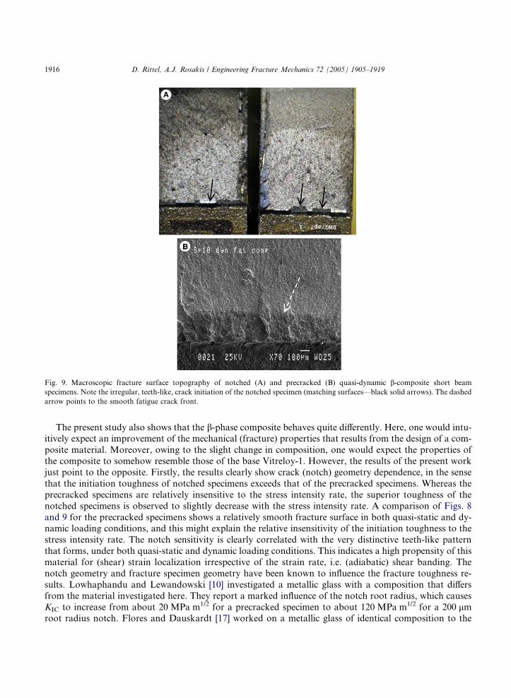
Fig. 9. Macroscopic fracture surface topography of notched (A) and precracked (B) quasi-dynamic b-composite short beam
specimens. Note the irregular, teeth-like, crack initiation of the notched specimen (matching surfaces—black solid arrows). The dashed
arrow points to the smooth fatigue crack front.
1916 D. Rittel, A.J. Rosakis / Engineering Fracture Mechanics 72 (2005) 1905–1919
The present study also shows that the b-phase composite behaves quite differently. Here, one would intu-itively expect an improvement of the mechanical (fracture) properties that results from the design of a com-
posite material. Moreover, owing to the slight change in composition, one would expect the properties of
the composite to somehow resemble those of the base Vitreloy-1. However, the results of the present work
just point to the opposite. Firstly, the results clearly show crack (notch) geometry dependence, in the sense
that the initiation toughness of notched specimens exceeds that of the precracked specimens. Whereas the
precracked specimens are relatively insensitive to the stress intensity rate, the superior toughness of the
notched specimens is observed to slightly decrease with the stress intensity rate. A comparison of Figs. 8
and 9 for the precracked specimens shows a relatively smooth fracture surface in both quasi-static and dy-namic loading conditions, and this might explain the relative insensitivity of the initiation toughness to the
stress intensity rate. The notch sensitivity is clearly correlated with the very distinctive teeth-like pattern
that forms, under both quasi-static and dynamic loading conditions. This indicates a high propensity of this
material for (shear) strain localization irrespective of the strain rate, i.e. (adiabatic) shear banding. The
notch geometry and fracture specimen geometry have been known to influence the fracture toughness re-
sults. Lowhaphandu and Lewandowski [10] investigated a metallic glass with a composition that differs
from the material investigated here. They report a marked influence of the notch root radius, which causes
KIC to increase from about 20 MPa m1/2 for a precracked specimen to about 120 MPa m1/2 for a 200 lmroot radius notch. Flores and Dauskardt [17] worked on a metallic glass of identical composition to the
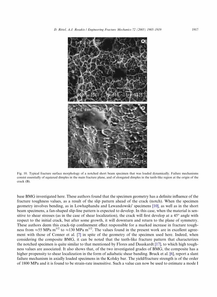
Fig. 10. Typical fracture surface morphology of a notched short beam specimen that was loaded dynamically. Failure mechanisms
consist essentially of equiaxed dimples in the main fracture plane, and of elongated dimples in the teeth-like region at the origin of the
crack (B).
D. Rittel, A.J. Rosakis / Engineering Fracture Mechanics 72 (2005) 1905–1919 1917
base BMG investigated here. These authors found that the specimen geometry has a definite influence of thefracture toughness values, as a result of the slip pattern ahead of the crack (notch). When the specimen
geometry involves bending, as in Lowhaphandu and Lewandowski� specimens [10], as well as in the short
beam specimens, a fan-shaped slip-line pattern is expected to develop. In this case, when the material is sen-
sitive to shear stresses (as in the case of shear localization), the crack will first develop at a 45� angle withrespect to the initial crack, but after some growth, it will downturn and return to the plane of symmetry.
These authors deem this crack-tip confinement effect responsible for a marked increase in fracture tough-
ness from �55 MPa m1/2 to �130 MPa m1/2. The values found in the present work are in excellent agree-
ment with those of Conner et al. [7] in spite of the geometry of the specimen used here. Indeed, whenconsidering the composite BMG, it can be noted that the teeth-like fracture pattern that characterizes
the notched specimen is quite similar to that mentioned by Flores and Dauskardt [17], to which high tough-
ness values are associated. It also shows that, of the two investigated grades of BMG, the composite has a
higher propensity to shear localization in the form of adiabatic shear banding. Bruck et al. [6], report a slant
failure mechanism in axially loaded specimens in the Kolsky bar. The yield/fracture strength is of the order
of 1800 MPa and it is found to be strain-rate insensitive. Such a value can now be used to estimate a mode I
1918 D. Rittel, A.J. Rosakis / Engineering Fracture Mechanics 72 (2005) 1905–1919
SIF at the onset of shear fracture. Keeping in mind the shear banding fracture mechanism, the slight
negative rate sensitivity appears to be qualitatively related to a ‘‘shear band toughness’’ in which adiabatic
shear bands form more easily than regular quasi-static shear bands. This point requires further study.
To illustrate adiabatic shear banding, let us neglect, as a first approximation, the notch geometrical ef-
fect. The shear strength of the material is sy = 900 MPa. The stress distribution ahead of a (static or station-ary) crack is given to a first order by
srh ¼KIffiffiffiffiffiffiffi2pr
p sinh2
� �cos2
h2
� �ð4Þ
For a typical toughness value of KdIC ¼ 100 MPa m1/2, a local stress equal to sy is reached at r = 245 lm.
While a more sophisticated analysis should rely on the exact solution for the stress field ahead of a notch,
this value is nevertheless an indication of the distance over which the yield stress is reached (assuming a
ideally-plastic material). In other words, this is also the typical size of the observed teeth, and it indeed
agrees with the observations.
As a final point, it appears throughout this work that through compositional changes, the b-composite is
not a simple modification of the base Vitreloy-1 BMG. It is a totally different material.
5. Conclusions
The dynamic fracture properties of Vitreloy-1 and b-composite Vitreloy-1 have been investigated. For
Vitreloy-1 two different techniques of determination of the dynamic initiation toughness have been used
and compared: CGS (Caltech) and one-point impact (Technion). For the composite, only one technique
was employed (one-point impact), and in both cases the failure mechanisms were characterized. The follow-ing conclusions can be drawn from the present study:
• Two radically different techniques yield very similar results for the impact toughness of Vitreloy-1. This
is the first round-robin of this kind and the results are very encouraging towards establishing intercom-
parisons between various laboratories, a point that is currently overlooked.
• Improved overall accuracy requires accurate identification of the onset of crack propagation, mostly at
the high loading rates.
• The initiation toughness of Vitreloy-1 is highly rate sensitive and it increases markedly at higher stressintensity rates.
• Within the investigated range of notch/crack-tip geometries, the material is relatively insensitive to the
crack/notch tip root radius.
b-Phase Vitreloy-1 composite was studied using Technion�s approach only, and the following conclu-
sions can be drawn:
• By contrast with Vitreloy-1, the fracture toughness (both static and dynamic) of this composite materialis highly dependent on the crack/notch root radius.
• The dynamic initiation toughness of precracked specimens is relatively insensitive to the stress intensity
rate.
• As expected, much larger KdIC values are observed in the case of rounded notches as opposed to sharp
cracks.
• However, the fracture toughness seems to decrease at higher stress intensity rates for notched specimens.
D. Rittel, A.J. Rosakis / Engineering Fracture Mechanics 72 (2005) 1905–1919 1919
• A distinctive failure mechanism was observed to operate in notched specimens, namely the formation of
shear steps (teeth-like) that form an approximate angle of 45� with respect to the fracture plane. This
mechanism was neither observed in the case of precracked specimens nor in the base Vitreloy-1 material.
• The specific notch-related failure mechanisms seems to indicate a higher propensity towards shear local-
ization (including adiabatic) in the b-composite, irrespective of the stress intensity rate, as compared withthe base Vitreloy-1.
• Finally, this work shows that the two materials react in a widely different manner to dynamic crack ini-
tiation, in spite of their relative compositional similarity.
Acknowledgements
Prof. W.L. Johnson and Dr. D. Conner of Caltech are acknowledged for kindly supplying the BMG
specimens and for useful discussions. D.R. acknowledges support from the Fund for Promotion of Re-
search at Technion. AJR acknowledges support through the NSF Grant CSEM.IRG-BMG to Caltech.
References
[1] Pampillo C. Flow and fracture in amorphous alloys. J Mater Sci 1975;10(7):1194–227.
[2] Inoue A, Zhang T, Matsumoto T. Production of amorphous cylinder and sheet of La55Al25Ni20 alloy by a metallic mold casting
method. Mater Trans Jpn Inst Met 1990;31(5):425–8.
[3] Zhang T, Inoue A, Matsumoto T. Amorphous Zr–Al–TM (TM = Co, Ni, Cu) alloys with significant supercooled region of over
100 K. Mater Trans Jpn Inst Met 1991;32(11):1005–10.
[4] Peker A, Johnson WL. A highly processable metallic-glass—Zr41.2Ti13.8Cu12.5Ni10.0Be22.5. Appl Phys Lett 1993;6(17):2342–4.
[5] Bruck HA, Christman T, Rosakis AJ, Johnson WL. Quasi-static constitutive behavior of Zr41.25Ti13.75Ni10Cu12.5Be22.5 bulk
amorphous-alloys. Scripta Metall Mater 1994;30(4):429–34.
[6] Bruck HA, Rosakis AJ, Johnson WL. The dynamic compressive behavior of beryllium bearing bulk metallic glasses. J Mater Res
1996;11(2):503–11.
[7] Conner RD, Rosakis AJ, Johnson WL, Owen D. Fracture toughness determination for a beryllium bulk bearing metallic glass.
Scripta Mater 1997;37(9):1373–8.
[8] Gilbert CJ, Ritchie RO, Johnson WL. Fracture toughness and fatigue-crack propagation in a Zr–Ti–Ni–Cu–Be bulk metallic
glass. Appl Phys Lett 1997;71(4):476–8.
[9] Gilbert CJ, Lippmann JM, Ritchie RO. Fatigue of a Zr–Ti–Cu–Ni–Be bulk amorphous metal: Stress/life and crack growth
behavior. Scripta Mater 1998;38(4):537–42.
[10] Lowhaphandu P, Lewandowski JJ. Fracture toughness and notched toughness of bulk amorphous alloy: Zr–Ti–Ni–Cu–Be.
Scripta Mater 1998;38(12):1811–7.
[11] Rosakis AJ. In: Epstein JS, editor. Experimental techniques in fracture. New York, NY: VCH Publishers Inc; 1993. p. 327–425.
[12] Weisbrod G, Rittel D. A method for dynamic fracture toughness determination using short beams. Int J Fract
2000;104(1):91–104.
[13] Rittel D, Weisbrod G. Dynamic fracture of tungsten base heavy alloys. Int J Fract 2001;212:87–98.
[14] Zehnder AT, Rosakis AJ. Dynamic fracture initiation and propagation in 4340 steel under impact loading. Int J Fract
1990;43:271–85.
[15] Malkin J, Tetelman AS. Relationship between KIC and microscopic strength for low alloy steels. Engng Fract Mech
1971;3:151–67.
[16] Rittel D, Maigre H. An investigation of dynamic crack initiation in PMMA. Mech Mater 1996;23(3):229–39.
[17] Flores KM, Dauskardt RH. Enhanced toughness due to stable crack tip damage zones in bulk metallic glass. Scripta Mater
1999;41(9):937–43.


![Dynamic Analysis of Application Delivery Network for ...jain/papers/ftp/profile.pdfabsolute times dynamic we applied dynamic profiling [15]. 2) Dynamic Profiling Dynamic profiling](https://static.fdocuments.us/doc/165x107/5b0b75c97f8b9a61448cc1b1/dynamic-analysis-of-application-delivery-network-for-jainpapersftp-times.jpg)