Dynamic formulation and performance evaluation of the...
12
Dynamic formulation and performance evaluation of the redundant parallel manipulator Yongjie Zhao a,b, , Feng Gao b a Department of Mechantronics Engineering, Shantou University, Shantou 515063, PR China b State Key Laboratory of Mechanical System and Vibration, Shanghai Jiao Tong University, Shanghai 200240, PR China article info Article history: Received 28 September 2007 Received in revised form 8 August 2008 Accepted 6 October 2008 Keywords: Inverse dynamics Redundant parallel manipulator Performance index Performance evaluation Principle of virtual work abstract The dynamic formulation and performance evaluation of the redundant parallel manipulator are presented in this paper. By means of the principle of virtual work and the concept of link Jacobian matrices, the inverse dynamic model of the redundant parallel manipulator is set up. It consists of six linear consistent equations with eight unknown quantities. Then, the optimum solution of the actuating torques is achieved by employing the Moore-Penrose inverse matrix. It is with minimum norm and least quadratic sum among the possible actuating torque vectors. A series of new dynamic performance indices with obvious physical meanings have been proposed in the paper. By decoupling the inverse dynamics in the exhaustive way, a novel dynamic performance index combining the acceleration, velocity and gravity terms of the dynamic equations has been presented to evaluate the dynamic characteristic of the redundant parallel manipulator. With the index, it is possible to control the performance in the different direction. The index has been applied to the dynamic characteristic evaluation of the redundant parallel manipulator in the simulation. It is general and can be used for the dynamic performance evaluation of other types of parallel manipulators. & 2008 Elsevier Ltd. All rights reserved. 1. Introduction A parallel manipulator is a closed-loop kinematic chain mechanism whose end-effector is linked to the base by several independent kinematic chains [1–3]. Due to their potential advantages such as high accuracy, rigidity, speed and so on, many investigations have been carried on the parallel manipulators since the concept was introduced. They have been successfully applied to the motion simulators, robotic end-effector and other circumstances like fast pick-and-place operation. Redundancy can usually improve the ability and performance of the parallel manipulator [4–13]. There are many advantages for the redundant parallel manipulator such as avoiding kinematic singularities, increasing workspace, improving dexterity, enlar- ging load capability and so on. In general, there are two different types of redundancy for the parallel manipulator: (a) kinematic redundancy and (b) actuation redundancy. A parallel manipulator is said to be kinematically redundant manipulator when its mobility of the mechanism is greater than the required degrees of freedom of the moving platform. On the other hand, a parallel manipulator is called redundantly actuated manipulator when the number of actuators is greater than the mobility of the mechan- ism. Redundant actuation in parallel manipulator can be im- plemented by the following approaches. The first one is to actuate some of the passive joints within the branches of the parallel manipulator. The second one is to add some additional branches beyond the minimum necessary to actuate the parallel manip- ulator. The last one may be the hybrid of the above two approaches. Like anything has two sides, the redundantly actuated parallel manipulator has also some disadvantages, though much attention has been paid to it. It is noted that the actuator redundancy does not affect the mobility of the parallel manip- ulator while maybe make it to be an over-constrained mechanism. The Jacobian matrix of this kind parallel manipulator which maps an m-dimensional velocity vector X ˙ in the operation space into an n-dimensional joint velocity vector q ˙ is not a square matrix any more. This will bring difficulties in the kinematics and dynamics analysis, especially for the dynamic performance evaluation. Performance evaluation of the parallel manipulator is still an open problem [14,15]. There are two basic criteria used for the general parallel manipulator, (i) the conditioning indices and (ii) the manipulability measures. Salisbury and Craig [16] introduced the condition number of the Jacobian matrix and Angeles [17,18] that used the inverse condition number as the kinematic dexterity index for the serial manipulators. Gosselin [19,20] adopted it to the parallel manipulators. The condition number should be as small as possible in order to achieve the best performance and the ARTICLE IN PRESS Contents lists available at ScienceDirect journal homepage: www.elsevier.com/locate/rcim Robotics and Computer-Integrated Manufacturing 0736-5845/$ - see front matter & 2008 Elsevier Ltd. All rights reserved. doi:10.1016/j.rcim.2008.10.001 Corresponding author. E-mail addresses: [email protected] (Y. Zhao), [email protected] (F. Gao). Robotics and Computer-Integrated Manufacturing ] (]]]]) ]]]–]]] Please cite this article as: Zhao Y, Gao F. Dynamic formulation and performance evaluation of the redundant parallel manipulator. Robot Comput Integr Manuf (2008), doi:10.1016/j.rcim.2008.10.001
Transcript of Dynamic formulation and performance evaluation of the...

ARTICLE IN PRESS
Robotics and Computer-Integrated Manufacturing ] (]]]]) ]]]–]]]
Contents lists available at ScienceDirect
Robotics and Computer-Integrated Manufacturing
0736-58
doi:10.1
� Corr
E-m
(F. Gao)
PleasRobo
journal homepage: www.elsevier.com/locate/rcim
Dynamic formulation and performance evaluation of the redundantparallel manipulator
Yongjie Zhao a,b,�, Feng Gao b
a Department of Mechantronics Engineering, Shantou University, Shantou 515063, PR Chinab State Key Laboratory of Mechanical System and Vibration, Shanghai Jiao Tong University, Shanghai 200240, PR China
a r t i c l e i n f o
Article history:
Received 28 September 2007
Received in revised form
8 August 2008
Accepted 6 October 2008
Keywords:
Inverse dynamics
Redundant parallel manipulator
Performance index
Performance evaluation
Principle of virtual work
45/$ - see front matter & 2008 Elsevier Ltd. A
016/j.rcim.2008.10.001
esponding author.
ail addresses: [email protected] (Y. Zh
.
e cite this article as: Zhao Y, Gao F.t Comput Integr Manuf (2008), doi:
a b s t r a c t
The dynamic formulation and performance evaluation of the redundant parallel manipulator are
presented in this paper. By means of the principle of virtual work and the concept of link Jacobian
matrices, the inverse dynamic model of the redundant parallel manipulator is set up. It consists of six
linear consistent equations with eight unknown quantities. Then, the optimum solution of the actuating
torques is achieved by employing the Moore-Penrose inverse matrix. It is with minimum norm and least
quadratic sum among the possible actuating torque vectors. A series of new dynamic performance
indices with obvious physical meanings have been proposed in the paper. By decoupling the inverse
dynamics in the exhaustive way, a novel dynamic performance index combining the acceleration,
velocity and gravity terms of the dynamic equations has been presented to evaluate the dynamic
characteristic of the redundant parallel manipulator. With the index, it is possible to control the
performance in the different direction. The index has been applied to the dynamic characteristic
evaluation of the redundant parallel manipulator in the simulation. It is general and can be used for the
dynamic performance evaluation of other types of parallel manipulators.
& 2008 Elsevier Ltd. All rights reserved.
1. Introduction
A parallel manipulator is a closed-loop kinematic chainmechanism whose end-effector is linked to the base by severalindependent kinematic chains [1–3]. Due to their potentialadvantages such as high accuracy, rigidity, speed and so on, manyinvestigations have been carried on the parallel manipulatorssince the concept was introduced. They have been successfullyapplied to the motion simulators, robotic end-effector and othercircumstances like fast pick-and-place operation.
Redundancy can usually improve the ability and performanceof the parallel manipulator [4–13]. There are many advantages forthe redundant parallel manipulator such as avoiding kinematicsingularities, increasing workspace, improving dexterity, enlar-ging load capability and so on. In general, there are two differenttypes of redundancy for the parallel manipulator: (a) kinematicredundancy and (b) actuation redundancy. A parallel manipulatoris said to be kinematically redundant manipulator when itsmobility of the mechanism is greater than the required degrees offreedom of the moving platform. On the other hand, a parallelmanipulator is called redundantly actuated manipulator when the
ll rights reserved.
ao), [email protected]
Dynamic formulation and10.1016/j.rcim.2008.10.001
number of actuators is greater than the mobility of the mechan-ism. Redundant actuation in parallel manipulator can be im-plemented by the following approaches. The first one is to actuatesome of the passive joints within the branches of the parallelmanipulator. The second one is to add some additional branchesbeyond the minimum necessary to actuate the parallel manip-ulator. The last one may be the hybrid of the above twoapproaches. Like anything has two sides, the redundantly actuatedparallel manipulator has also some disadvantages, though muchattention has been paid to it. It is noted that the actuatorredundancy does not affect the mobility of the parallel manip-ulator while maybe make it to be an over-constrained mechanism.The Jacobian matrix of this kind parallel manipulator which mapsan m-dimensional velocity vector X in the operation space into ann-dimensional joint velocity vector q is not a square matrix anymore. This will bring difficulties in the kinematics and dynamicsanalysis, especially for the dynamic performance evaluation.
Performance evaluation of the parallel manipulator is still anopen problem [14,15]. There are two basic criteria used for thegeneral parallel manipulator, (i) the conditioning indices and (ii)the manipulability measures. Salisbury and Craig [16] introducedthe condition number of the Jacobian matrix and Angeles [17,18]that used the inverse condition number as the kinematic dexterityindex for the serial manipulators. Gosselin [19,20] adopted it tothe parallel manipulators. The condition number should be assmall as possible in order to achieve the best performance and the
performance evaluation of the redundant parallel manipulator.

ARTICLE IN PRESS
Y. Zhao, F. Gao / Robotics and Computer-Integrated Manufacturing ] (]]]]) ]]]–]]]2
manipulator is regarded as in the kinematic isotropy when thecondition number is one. A global conditioning index [21], whichcan be implemented with the numerical integration technique,was presented by Gosselin due to the following facts: (i) thecondition necessary to generate an isotropy cannot providesufficient design constraints to achieve a unique solution. (ii)The global kinematic performance cannot be guaranteed simplyby conducting local optimal design. However, as Lipkin and Duffy[22] and Doty [23,24] et al. pointed out, significant problems maybe caused when using the condition number of the Jacobianmatrix with non-homogeneous physical units in the optimaldesign and control. The condition number of the Jacobian matrixwill not be invariant under scaling of the dimensions of themanipulator when the position and orientation of the end-effectorare included in the kinematic equations. In order to avoid the unitinconsistency problem, some works [25–27] had been done basedon the principle that the plane is determined by three non-collinear points. Gosselin [25] derived a new Jacobian matrix thattransforms actuator velocities into the linear velocities of two orthree nonlinear points on the end-effector for the serial planar orspatial manipulators and then defined a new conditioning indexbased on the new Jacobian matrix. Kim [28] adopted the newconditioning index to the optimization of the Gough–Stewartparallel manipulator. The concept of kinematic manipulabilitywas introduced by Yoshikawa [29] as a measure of themanipulator capability for executing a specific task in a givenconfiguration. He defined the manipulability measure as ageneralized determinant of the Jacobian matrix and separatedthe total manipulability measure into translational and rotationalmanipulability measure later [30]. Hong and Kim [31] defined anew manipulability measure, which included the total volume ofmanipulability ellipsoid and the condition number of the Jacobianmatrix, and optimized the Eclipse parallel manipulator bymaximizing the manipulability measure.
In order to investigate the dynamic characteristic of theparallel manipulator, the dynamic model must be set up firstly.Many works [32–77] can be found on the dynamics of the parallelmanipulators. Several approaches have been applied to thedynamics analysis of parallel manipulators. They mainly can beclassified into four categories: the Newton-Euler method [32–41],Lagrangian method [42–48], Kane’s method [49,50] and virtualwork principle method [51–62]. In fact, the inverse dynamics ofparallel manipulators almost involve all the mechanics principles.Along with these mechanics principles, many mathematicmethods such as screw theory [63], Lie algebra [64], naturalorthogonal complement [65–67], motor algebra [68,69], grouptheory [70], symbolic programming [70,71], geometric approach[72], parallel computational algorithms [73] and system identifi-cation [74] have also been adopted to the dynamics of parallelmanipulators. As a matter of fact, the results of actuate forces/torques computed by different methods are equivalent [75].Theoretically, it can be concluded that there is no trouble inmodeling the dynamics of parallel manipulators. Much attentionshould be focused on the model accuracy, computation efficiencyand practical application. It should be also pointed that thenumber of the unknown quantities is larger than that of the linearconsistent equations for the inverse dynamics of the redundantparallel manipulator. So the solution is infinite on this condition.The most common strategy to solve this kind of problem is byminimizing the Euclidian norm of the actuating torque vectors.
The dynamic models are strongly nonlinear equations, whichmake it difficult to predict the dynamic performance of themanipulator. However, the dynamic performance of the parallelmanipulator should be taken into account for the design, moreadvanced control and trajectory planning. Several dynamic perfor-mance indices have been presented in the literatures [78–87]. Ma
Please cite this article as: Zhao Y, Gao F. Dynamic formulation anRobot Comput Integr Manuf (2008), doi:10.1016/j.rcim.2008.10.001
and Angeles [78,79] introduced the concept of dynamic condition-ing index, which was defined as the least-square difference betweenthe generalized inertia matrix and an isotropic matrix. Asadaintroduced the generalized inertia ellipsoid as a tool to measure thecapability of changing end-effector’s velocity in different directionsfor the given kinetic energy [80,81]. Yoshikawa [82] extended theconcept of kinematic manipulability ellipsoid to dynamic manipul-ability ellipsoid for measuring the case of changing the end-effector’s configuration by a set of joint torques with fixedmagnitude (Euclidian norm). Huang [51,83] adopted the maximumsingular value of the generalized inertia matrix or its row vectormatrix to evaluate the dynamic characteristic of the parallelmanipulator. Since the velocity term and the gravity term of thedynamic model are neglected in the indices, they are not very suitedfor the dynamic performance evaluation of the high speedmanipulator or the heavy manipulator used for the application ofthe large load requirement. In addition, the generalized inertiamatrix is an approximate expression [83]. The key at the basis of thedefinition of the above performance measures is the generalizedinertia matrix which describes the mapping between the jointforces/torques and the accelerations.
According to the matrix theory, the condition number is theratio of the maximum singular value to the minimum singularvalue of the matrix and the manipulability can be represented bythe continued multiplication of all the singular values. Thoughthey have been used widely in robotics, they are not veryappropriate for the parallel manipulators [88]. Some problemsarise when applying them to the performance evaluation: (i) forthe out-parallel manipulator, there are three kinds of singularconfigurations which make the manipulability ellipsoid thatcannot measure the performance quantitatively. Furthermore,when take the manipulability ellipsoid is taken as the perfor-mance index of the parallel manipulator, the volume and theshape of the ellipsoid should be taken into account which makesthe performance prediction become complex. As for the conditionnumber, it cannot be a measurement of distance from asingularity while used widely in the in-parallel manipulators.Huang [89] found that the 2-dof out-parallel manipulator mayalso be nearly at the singular configuration when the conditionnumber of the Jacobian matrix is one. In addition, the denomi-nator of the Jacobian matrix will be lost in the computation of thecondition number when the end-effector is on the center line ofthe workspace. (ii) The distributions of the singular values cannotbe achieved from the condition number, which represents the ill-condition of the matrix and can be thought as a factor amplifyingthe errors of the manipulator or the measure of the matrixreversibility. (iii) The condition indices and the manipulabilitymeasures do not have very obvious physical meanings. (iv) Theconditioning indices and the manipulability measures cannot beapplied to the redundant parallel manipulator directly since theJacobian matrix and the generalized inertia matrix are not squarematrix any more. In fact, there is little work on the dynamiccharacteristic evaluation of the redundant parallel manipulator.
The aim of this paper is to present the work on the dynamicformulation and performance evaluation of the redundant parallelmanipulator. The dynamical equations of the redundant parallelmanipulator have been formulated by mean of the principle ofvirtual work and the concept of link Jacobian matrices [2,56]. Byemploying the Moore-Penrose inverse matrix, the optimumsolution of the actuating torques is achieved. It is with minimumnorm and least quadratic sum among the possible actuatingtorque vectors. Then, a series of new dynamic performance indiceswith obvious physical meanings have been proposed in the paper.By decoupling the inverse dynamics in the exhaustive way, a noveldynamic performance index combining the acceleration, velocityand gravity terms of the dynamic equations is presented to
d performance evaluation of the redundant parallel manipulator.
ARTICLE IN PRESS
Y. Zhao, F. Gao / Robotics and Computer-Integrated Manufacturing ] (]]]]) ]]]–]]] 3
evaluate the dynamic characteristic of the redundant parallelmanipulator. It has been applied to the dynamic perfor-mance evaluation of the redundant parallel manipulator in thesimulation.
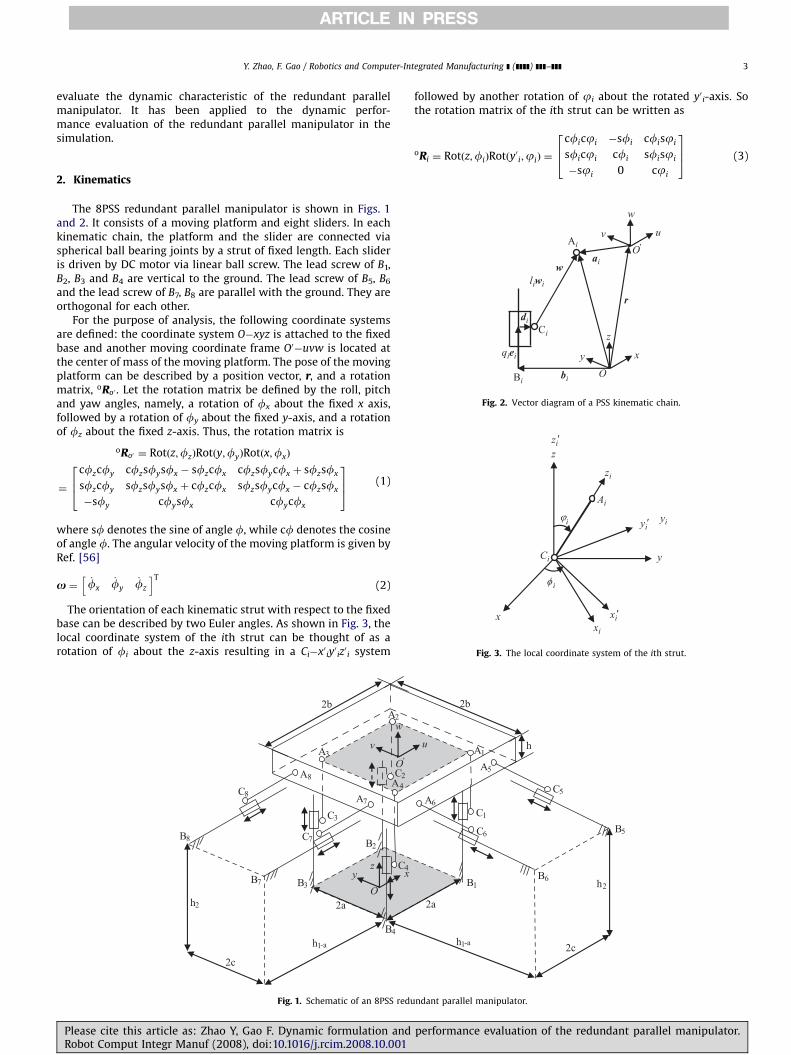
xy
z
O
uv
w
O'
bi
ai
r
qiei
liwiw
di
Bi
Ai
Ci
Fig. 2. Vector diagram of a PSS kinematic chain.
Ci
Ai
yi′yi
zi′z
x
zi
y
xi′xi
iφ
iϕ
Fig. 3. The local coordinate system of the ith strut.
2. Kinematics
The 8PSS redundant parallel manipulator is shown in Figs. 1and 2. It consists of a moving platform and eight sliders. In eachkinematic chain, the platform and the slider are connected viaspherical ball bearing joints by a strut of fixed length. Each slideris driven by DC motor via linear ball screw. The lead screw of B1,B2, B3 and B4 are vertical to the ground. The lead screw of B5, B6
and the lead screw of B7, B8 are parallel with the ground. They areorthogonal for each other.
For the purpose of analysis, the following coordinate systemsare defined: the coordinate system O�xyz is attached to the fixedbase and another moving coordinate frame O0�uvw is located atthe center of mass of the moving platform. The pose of the movingplatform can be described by a position vector, r, and a rotationmatrix, oRo0 . Let the rotation matrix be defined by the roll, pitchand yaw angles, namely, a rotation of fx about the fixed x axis,followed by a rotation of fy about the fixed y-axis, and a rotationof fz about the fixed z-axis. Thus, the rotation matrix is
oRo0 ¼ Rotðz;fzÞRotðy;fyÞRotðx;fxÞ
¼
cfzcfy cfzsfysfx � sfzcfx cfzsfycfx þ sfzsfx
sfzcfy sfzsfysfx þ cfzcfx sfzsfycfx � cfzsfx
�sfy cfysfx cfycfx
264
375 (1)
where sf denotes the sine of angle f, while cf denotes the cosineof angle f. The angular velocity of the moving platform is given byRef. [56]
x ¼ _fx_fy
_fz
h iT(2)
The orientation of each kinematic strut with respect to the fixedbase can be described by two Euler angles. As shown in Fig. 3, thelocal coordinate system of the ith strut can be thought of as arotation of fi about the z-axis resulting in a Ci�x0iy
0iz0i system
B
B
B
C
C
C
A
A
A
xyz
O
v
w
O'
2a
A
A
C
C
B
B
2b
2c
h
h
2
3
4
2
3
4
2
3
4
7
8
7
8
7
8
2
1-a
Fig. 1. Schematic of an 8PSS redu
Please cite this article as: Zhao Y, Gao F. Dynamic formulation andRobot Comput Integr Manuf (2008), doi:10.1016/j.rcim.2008.10.001
followed by another rotation of ji about the rotated y0 i-axis. Sothe rotation matrix of the ith strut can be written as
oRi ¼ Rotðz;fiÞRotðy0i;jiÞ ¼
cficji �sfi cfisji
sficji cfi sfisji
�sji 0 cji
264
375 (3)
B
C
Au
2a
A
AC
C B
B
2b
2c
h
h
1
1
1
5
65
6 5
62
1-a
h
ndant parallel manipulator.
performance evaluation of the redundant parallel manipulator.

ARTICLE IN PRESS
Y. Zhao, F. Gao / Robotics and Computer-Integrated Manufacturing ] (]]]]) ]]]–]]]4
The unit vector along the lead screw in the coordinate systemO�xyz is
wi¼oRi
iwi¼oRi
0
0
1
264
375 ¼
cfisji
sfisji
cji
264
375 (4)
So the Euler angles fi and ji can be computed as the following
cji ¼ wiz
sji ¼
ffiffiffiffiffiffiffiffiffiffiffiffiffiffiffiffiffiffiffiffiffiw2
ix þw2iy
q; ð0pjiopÞ
sfi ¼ wiy=sji
cfi ¼ wix=sji
if ji ¼ 0; then fi ¼ 0 (5)
2.1. Position analysis
As shown in Fig. 2, the closed-loop position equationassociated with the ith kinematic chain can be written as
r þ ai ¼ liwi þ bi þ di þ qiei; i ¼ 1;2; . . . ;8 (6)
where r, qi, ei, wi, ai bi and di denote the vector OO0, the jointvariable, the unit vector along the lead screw, the unit vector alongstrut CiAi, the vector O0Ai, the vector OBi and the vector from thelead screw to the center point of the joint Ci, respectively.
So the inverse position solution can be achieved
qi ¼
ffiffiffiffiffiffiffiffiffiffiffiffiffiffiffiffiffiffiffiffiffiffiffiffiffiffiffiffiffiffiffiffiffiffiffiffiffiffiffiffiffiffiffiffiffiffiffiffiffiffiffiffiffiffiffiffiffiffiffiffiffiffiffiffiffiffiffiffiffiffiffiffiffiffiffiffiffiffiffiffiffiffiffiffiffiffiffiffiffiffiffiffiffiffiffiffiffiffiffiffiffiðr þ ai � liwi � bi � diÞ
Tðr þ ai � liwi � bi � diÞ
q,
i ¼ 1;2; . . . ;8 (7)
2.2. Velocity analysis
Taking the derivative of Eq. (6) with respects to time yields
_qiei þxi � liwi ¼ v þx� ai (8)
where xi and v denote the angular velocity of the strut CiAi, thelinear velocity of the moving platform.
Taking the dot product of both sides of Eq. (8) with wi yields
_qi ¼wT
i
wTi ei
ðai �wiÞT
wTi ei
" #v
x
� �(9)
Rewriting Eq. (9) in the matrix form yields
_q ¼ J�1q Jx
_X ¼ J _X (10)
where
_q ¼ _q1 _q2 _q3 _q4 _q5 _q6 _q7 _q8
h iT(11)
_X ¼v
x
� �(12)
Jq ¼ diagðwT1e1 wT
2e2 wT3e3 wT
4e4 wT5e5 wT
6e6 wT7e7 wT
8e8 Þ
(13)
Jx ¼w1 w2 w3 w4 w5 w6 w7 w8
a1 �w1 a2 �w2 a3 �w3 a4 �w4 a5 �w5 a6 �w6 a7 �w7 a8 �w8
" #T
(14)
J ¼ J�1q Jx ¼ ½ J
T1 JT
2 JT3 JT
4 JT5 JT
6 JT7 JT
8 �T (15)
where J is the Jacobian matrix which maps the velocity vector Xinto the joint velocity vector q.
Please cite this article as: Zhao Y, Gao F. Dynamic formulation anRobot Comput Integr Manuf (2008), doi:10.1016/j.rcim.2008.10.001
2.3. Link velocity analysis
The linear velocity of the point Ai in the Ci�x0 iy0iz0i coordinate
system is
ivAi ¼ _qiiei þ
ixi � liiwi ¼
iv þ ix� ia (16)
Since ixiTiwi ¼ 0, cross multiplying both sides of Eq. (16) with
iwi, so the angular velocity of the driven parallelogram arm isobtained as
ixi ¼1
liðiwi �
ivAi �iwi � _qi
ieiÞ ¼1
liðSðiwiÞ
ivAi � SðiwiÞ _qiieiÞ (17)
where
SðiwiÞ ¼
0 �iwiziwiy
iwiz 0 �iwix
�iwiyiwix 0
2664
3775 (18)
Substituting Eqs. (9) and (16) into Eq. (17) then yields
ixi ¼1
liSðiwiÞ
iRo �SðiwiÞSðiaiÞ
iRo
h i(
� ðiwi �ieiÞ
wTi
wTi ei
ðai �wiÞT
wTi ei
" #)v
x
" #
¼ J iov
x
" #(19)
where
SðiaiÞ ¼
0 �iaiziaiy
iaiz 0 �iaix
�iaiyiaix 0
2664
3775 (20)
iRo¼oR�1
i ¼oRT
i (21)
The velocity of the center of the ith strut in the Ci�x0iy0iz0i
coordinate system is
ivi ¼ivAi �
ixi �li2
iwi (22)
Substituting Eqs. (9), (16) and (19) into Eq. (22) then yields
ivi ¼iRo �SðiaiÞ
iRo
h iþ
li2
SðiwiÞJio
� �v
x
� �¼ J iv
v
x
� �(23)
Rewrite the linear and angular velocity of the ith strut in thematrix form:
ivi
ixi
" #¼
Jiv
J io
" #v
x
� �¼ Jivo
v
x
� �(24)
where Jivo is the link Jacobian matrix which maps thevelocity of the moving platform in the task space intothe velocity of the ith strut in the Ci�x0 iy
0iz0i coordinate
system.
d performance evaluation of the redundant parallel manipulator.

ARTICLE IN PRESS
Y. Zhao, F. Gao / Robotics and Computer-Integrated Manufacturing ] (]]]]) ]]]–]]] 5
2.4. Acceleration analysis
Taking the derivative of Eq. (8) with respects to time gives
_v ¼ €qiei � _x� ai �x� ðx� aiÞ þ _xi � liwi þxi � ðxi � liwiÞ
(25)
Taking the dot product of both sides of Eq. (25) with wi andsimplifying yields
€qi ¼1
wTi ei
ðwTi_v þ ðai �wiÞ
T _xþwTi ðx� ðx� aiÞÞ
�wTi ðxi � ðxi � liwiÞÞÞ
¼ JTi
_v
_x
" #þ
1
wTi ei
ððwTi xÞða
Ti xÞ � ðw
Ti aiÞðx
TxÞ þ lijxi �wij2Þ
(26)
Rewriting Eq. (26) in the matrix form yields
€q ¼ J €X þ V (27)
where
V ¼ V1 V2 V3 V4 V5 V6 V7 V8� �T
(28)
Vi ¼1
wTi ei
ððwTi xÞða
Ti xÞ � ðw
Ti aiÞðx
TxÞ þ lijxi �wij2Þ (29)
2.5. Link acceleration analysis
Taking the derivative of Eq. (8) with respects to time in theCi�x0iy
0iz0i coordinate system yields
i _v ¼ €qiiei �
i _x� iai �ix� ðix� iaiÞ
þ i _xi � liiwi þ
ixi � ðixi � li
iwiÞ (30)
Cross multiplying both sides of Eq. (30) with iwi then yields
i _x ¼1
liðiwi �
i _v � ðiwi �ieiÞ €qi �
iwi � ðiai �
i _xÞ
þ iwi � ðix� ðix� iaiÞÞ
� iwi � ðixi � ð
ixi �iwiÞÞÞ (31)
Substituting Eq. (26) into Eq. (31) and simplifying yields
i _x ¼ Jio_v
_x
" #þ
1
liðD1 þD2Þ (32)
where
D1 ¼ �ðiwi �
ieiÞ
wTi ei
ððwTi xÞða
Ti xÞ � ðw
Ti aiÞðx
TxÞ þ lijxi �wij2Þ (33)
D2 ¼ ðixT
iiaiÞð
iwi �ixiÞ � ð
ixTixÞðiwi �iaiÞ (34)
Taking the derivative of Eq. (22) with respects to time yields
i _vi ¼i _vAi �
li2
i _xi �iwi �
ixi �ixi �
li2
iwi
¼ i _v � SðiaiÞ
i _xþ Sði _xÞSðixÞiai
þli2
SðiwiÞi _xi �
li2
SðixiÞSðixiÞ
iwi (35)
Substituting Eq. (32) into Eq. (35) and simplifying yields
i _vi ¼ J iv
_v
_x
" #þ SðixiÞSð
ixiÞiai
þ1
2SðiwiÞðD1 þD2Þ �
li2
SðixiÞSðixiÞ
iwi (36)
Please cite this article as: Zhao Y, Gao F. Dynamic formulation andRobot Comput Integr Manuf (2008), doi:10.1016/j.rcim.2008.10.001
3. Inverse dynamic formulation
3.1. Applied and inertia wrenches
According to the D’Alembert’s principle, the force acting on thecenter of mass of each link consists of two parts: the inertial forceand the gravity force. Similarly, the moment acting on each rigidbody is the inertial moment. Assuming there is no frictional forcefor the whole robot system. The resultant of applied and inertiaforces exerted at the center of the mass of the moving platform is
Q P ¼f P
nP
" #¼
f e þmpg �mp _v
ne �oIp _x�x� ðoIpxÞ
" #(37)
where fe and ne are the external force and moment exerted at thecenter of mass of the moving platform, oIp ¼
oRo0o0Ip
o0Ro is theinertia matrix of the moving platform taken about the center ofmass expressed in the O�xyz coordinate system and mp is itsmass.
The resultant of applied and inertia forces exerted at the centerof mass of the ith strut can be expressed in the Ci�x0iy
0iz0i
coordinate system as
iQ i ¼
if iini
" #¼
miiRog �mi
i _vi
�iIii _xi �
ixi � ðiIi
ixiÞ
" #(38)
where iIi is the inertia matrix of the ith cylindrical strut abouttheir respective centers of mass expressed in the Ci�x0iy
0iz0i
coordinate system and mi is its mass.There is pure translational motion for the slider, so the
resultant of applied and inertia forces exerted at the center ofmass of the slider can be expressed in the O�xyz coordinatesystem as
f qi ¼ ðmqig �mqi €qiÞTei (39)
where mqi and qi are the mass and the acceleration of the slider.There is pure rotation motion for the lead screw, coupler and
motor rotor, so the resultant of applied and inertia forces exertedat the screw–coupler–rotor is
Ni ¼ ti � ðILi þ ICi þ IMiÞ€yi (40)
where ILi, ICi and IMi are the rotary inertia of the lead screw, couplerand motor rotor, respectively, ti is the input torque actuated by themotor, €yi is the angular acceleration of the screw–coupler–rotor.The relationship between the lead screw motion and the slidermotion is €yi ¼ ð2p=piÞ €qi. Where pi ¼ 0.05 m�1 is the lead of thelinear ball screw. Other than the speed reduction caused by thepitch of the lead screws there is no speed reducer for theredundant parallel manipulator, otherwise the reduction ratioshould be included in Eq. (40).
3.2. Equations of motion
According to the D’Alembert’s principle, the principle of thevirtual work can be extended from the static to the dynamic case.It can be stated as: the virtual work of the external forces appliedto the system must be zero. For this redundant parallelmanipulator it can be expressed in the formula:
dxTpQ p þ
X8
i¼1
dixTi
iQ i þ dqTf q þ dhTN ¼ 0 (41)
where
dq ¼ dq1 dq2 dq3 dq4 dq5 dq6 dq7 dq8
h iT(42)
performance evaluation of the redundant parallel manipulator.
ARTICLE IN PRESS
Y. Zhao, F. Gao / Robotics and Computer-Integrated Manufacturing ] (]]]]) ]]]–]]]6
dh ¼ dy1 dy2 dy3 dy4 dy5 dy6 dy7 dy8� �T¼ diag
2pp1
2pp2
2pp3
2pp4
2pp5
2pp6
2pp7
2pp8
!dq
¼ Adq (43)
f q ¼f q1 f q2 f q3 f q4 f q5 f q6 f q7 f q8
h iT(44)
N ¼ N1 N2 N3 N4 N5 N6 N7 N8� �T
(45)
In Eq. (41), the resultant of the applied and inertia forces iQi andits corresponding virtual displacement dixi are expressed in theCi�x0iy
0iz0i coordinate system. From Eq. (24), the relationship
between the above virtual displacement dixi and the virtualdisplacement dxp is determined by
dixTi ¼ dxT
pJTivo (46)
The relationship between the virtual displacement dq and dxp is
dqT ¼ dxTpJT (47)
Substituting Eqs. (43), (46) and (47) into Eq. (41) yields
dxTpQ p þ
X8
i¼1
dxTpJT
ivoiQ i þ dxT
pJTf q þ dxTpJTATN ¼ 0 (48)
Since Eq. (48) is always valid for any dxp, it must follow that
Q p þX8
i¼1
JTivo
iQ i þ JTf q þ JTATN ¼ 0 (49)
Eq. (49) can be written as
JTATs ¼ JTATILCM€h� Q p �
X8
i¼1
JTivo
iQ i � JTf (50)
where
ILCM ¼ diagð ILCM1 ILCM2 ILCM3 ILCM4 ILCM5 ILCM6 ILCM7 ILCM8 Þ
(51)
ILCMi ¼ ILi þ ICi þ IMi (52)
There are eight unknown quantities in the six linear consistentequations. So the solution is infinite. The most common strategyto solve this kind of problem is by minimizing the Euclidian normof the actuating torque vector:
s ¼ �A�TðJTÞþ Q p þ
X8
i¼1
JTivo
iQ i þ JTf q
!þ ILCM
€h
¼ �A�TðJTÞþ Q p þ
X8
i¼1
JTivo
iQ i þ JTf q
!þ ILCMA €q (53)
The physical significance of the above equation is that amongthe possible actuating torque vectors, the optimum solution iswith minimum norm and least quadratic sum. J+ is the Moore-Penrose inverse of the Jacobian matrix. As for any Jacobian matrix,there exists a unitary matrices UAUm�m and VAUn�n such that
D ¼ UHJV ¼
s1
s2
. ..
sr
0
266666664
377777775
(54)
is diagonal. UH is the conjugate transpose of U.So
Jþ ¼ VDþUH (55)
Please cite this article as: Zhao Y, Gao F. Dynamic formulation anRobot Comput Integr Manuf (2008), doi:10.1016/j.rcim.2008.10.001
Dþ ¼
s�11
s�12
. ..
s�1r
0
266666664
377777775
(56)
when JARmm�n, J+
¼ JT(JJT)�1¼ Jx
T(JxJxT)�1Jq.
Substituting Eqs. (37)–(40) into Eq. (53) yields
s ¼ � A�T JT� �þ f e
ne
" #� A�T JT
� �þ mpg
0
" #þX8
i¼1
JTivo
miiRog
0
" #(
þ JT ðmq1gÞTe1 ðmq2gÞTe2 ðmq3gÞTe3 ðmq4gÞTe4
h
ðmq5gÞTe5 ðmq6gÞTe6 ðmq7gÞTe7 ðmq8gÞTe8
iT)
þ A�T JT� �þ mp _v
oIp _x
" #þX8
i¼1
JTivo
mii _vi
iIii _xi
" #(
þJT mq1 €q1 mq2 €q2 mq3 €q3 mq4 €q4 mq5 €q5 mq6 €q6 mq7 €q7 mq8 €q8
h iT)
þ ILCMA €qþ A�T JT� �þ 0
x� ðoIpxÞ
" #þX8
i¼1
JTivo
0
ixi � ðiIi
ixiÞ
" #( )
(57)
where 0 ¼ ½0 0 0 �T.From Eq. (57), it is shown that the input torques are determined
by the structure parameters, the position parameters, the kine-matics parameters (including the velocity and the acceleration), thegravity term and the term caused by the external force and momentexerted at the moving platform. Substituting Eqs. (24), (31) and (36)into Eq. (57) and simplifying, the inverse dynamic model of theredundant parallel manipulator is achieved
s ¼ DðqÞ €qþ hðq; _qÞ þ GðqÞ � A�TJ�Tf e
ne
" #(58)
where D(q)q is the acceleration term, h(q,q) is the velocity term andG(q) is the gravity term of the inverse dynamic equations.
4. Performance evaluation
4.1. Kinematic performance evaluation
The relationship between the slider velocity and the inputangular velocity of the motor rotor is
_h ¼ A _q (59)
where _h and q are the input rotor angular velocity and the velocityof the slider, respectively.
So
_h ¼ A _q ¼ AJ _X ¼ Jy _X ¼ ½ Jyv Jyo �v
x
" #
¼ ½ Jy1 Jy2 Jy3 Jy4 Jy5 Jy6 �v
x
" #(60)
where Jy is the matrix which maps the velocity of the movingplatform into the angular velocity of the motor rotor, Jyj is thecolumn vector component of the matrix Jy, Jyv and Jyo are thepartitioned matrix component of the matrix Jy.
When the moving platform translates along or rotates aboutthe x-, y- and z-axis in the unit velocity, the input angular velocityof the motor rotor is
_hj ¼ Jyvj ¼ Jyj; ðj ¼ 1;2; . . . ;6Þ (61)
d performance evaluation of the redundant parallel manipulator.

ARTICLE IN PRESS
Y. Zhao, F. Gao / Robotics and Computer-Integrated Manufacturing ] (]]]]) ]]]–]]] 7
where
v1 ¼ ½1 0 0 0 0 0 �T (62a)
v2 ¼ ½0 1 0 0 0 0 �T (62b)
v3 ¼ ½0 0 1 0 0 0 �T (62c)
v4 ¼ ½0 0 0 1 0 0 �T (62d)
v5 ¼ ½0 0 0 0 1 0 �T (62e)
v6 ¼ ½0 0 0 0 0 1 �T (62f)
are used to represent the unit (angular) velocity of the movingplatform when it translates along or rotates about the x-, y- and z-
axis. They will also be used later to denote the unit (angular)acceleration of the moving platform when it translates along orrotates about the x-, y- and z-axis.
In general, when the moving platform moves in the arbitraryunit velocity
v ¼X6
j¼1
gjvj;X6
j¼1
g2j ¼ 1; kvk2
2 ¼ 1
0@
1A (63)
The input angular velocity vector of the motor rotor is
_hw ¼ Jyv ¼X6
j¼1
gjJyj (64)
The maximum input angular velocity is
_ywmax ¼_hw
1pX6
j¼1
gj
��� ��� Jyj
1¼X6
j¼1
gj
��� ��� _hj
1
pmax _h1
1
_h2
1
_h3
1
_h4
1
_h5
1
_h6
1
¼ max Jy1
1
Jy2
1
Jy3
1
Jy4
1
Jy5
1
Jy6
1
� �¼ max
i¼1;2;...;8;j¼1;2;...;6Jyij
� �¼ Jy 0
1¼ _ymax (65)
So _hmax ¼ Jy 0
1is taken as the kinematic performance index. It
is the maximum input angular velocity when the moving platformtranslates along or rotates about the x-, y- and z-axis in the unitvelocity.
Similarly, when the moving platform has a pure translationalmotion, the following index is adopted to evaluate the transla-tional capability of the redundant parallel manipulator.
_hv max ¼ kJyvk01 (66)
If the moving platform has a pure rotational motion
_homax ¼ kJyok01 (67)
is taken as the index to evaluate the rotational capability of theredundant parallel manipulator.
4.2. Dynamic performance evaluation
From Eqs. (57) and (58), the dynamic model of the redundantparallel manipulator can be written as
s ¼MðXÞ €X þ VðX; _XÞ þ gðXÞ � A�TJ�Tf e
ne
" #
¼ sa þ sv þ sg þ se (68)
Please cite this article as: Zhao Y, Gao F. Dynamic formulation andRobot Comput Integr Manuf (2008), doi:10.1016/j.rcim.2008.10.001
where
MðXÞ ¼ A�TðJTÞþ
mpE3
oIp
" #þX8
i¼1
JTivmiJ iv þ
X8
i¼1
JTio
iIiJ io
!
þ A�Tdiagðmq1 mq2 mq3 mq4 mq5 mq6 mq7 mq8 ÞJ
þ AILCMJ
¼ ½M1 M2 M3 M4 M5 M6 �
¼ Mv Mo� �
(69)
is the generalized inertia matrix of the redundant parallelmanipulator which maps the acceleration of the moving platforminto the actuating torques. E3 denotes the unit matrix of orderthree. V(X,X) and g(X) are the velocity term and the gravity termof the inverse dynamic equations, respectively.
4.2.1. Torques caused by the acceleration term
When the moving platform accelerates from the stationary inthe unit acceleration, translates along or rotates about the x-, y-
and z-axis, the input torque caused by the acceleration term is
saj ¼MðXÞvj; j ¼ 1;2; . . . ;6 (70)
So the maximum input torque caused by the acceleration termis
ta max ¼ maxðksajk1Þ ¼ maxðkMjk1Þ ¼ maxðkMijkÞ ¼ kMk01;
i ¼ 1;2; . . . ;8; j ¼ 1;2; . . . ;6
(71)
It is taken as the dynamic performance index to evaluate theacceleration capability of the redundant parallel manipulator. Whenthe moving platform has a pure linear acceleration motion, themaximum input torque caused by the acceleration term is taken asthe index to evaluate the translational acceleration capability
tav max ¼ kMvk01 (72)
If the moving platform has a pure angular acceleration motion,the following maximum input torque caused by the accelerationterm is adopted to evaluate the rotational acceleration capability ofthe parallel manipulator
tao max ¼ kMok01 (73)
4.2.2. Torques caused by the velocity term
From Eqs. (57) and (68), the torque caused by the velocity termis
svj ¼ VðX; _XÞj _X¼vj j¼1;2;...;6 (74)
So the maximum input torque caused by the velocity is
tv max ¼ maxðksvjk1Þ; j ¼ 1;2; . . . ;6 (75)
When the moving platform has a pure translational or a purerotational motion, the maximum input torques caused by thevelocity term are the following, respectively
svv max ¼maxðksvjk1Þ; j ¼ 1;2;3 (76)
tvo max ¼ maxðksvjk1Þ; j ¼ 4;5;6 (77)
4.2.3. Torques caused by the gravity term
The torque caused by the gravity term is
tg ¼ gðXÞ (78)
So the maximum input torques caused by the gravity term is
tg max ¼ ksgk1 (79)
performance evaluation of the redundant parallel manipulator.

ARTICLE IN PRESS
Table 3The length of the strut CiAi (m)
1 2 3 4 5 6 7 8
li 1.000000 1.000000 1.000000 1.000000 1.000000 1.000000 1.000000 1.000000
Table 4The mass parameters of the manipulator (kg)
1 2 3 4 5 6 7 8
mi 20 20 20 20 20 20 20 20
mqi 50 50 50 50 50 50 50 50
Y. Zhao, F. Gao / Robotics and Computer-Integrated Manufacturing ] (]]]]) ]]]–]]]8
4.2.4. Dynamic performance index
When the moving platform has a maximum (angular) accel-eration Zi ¼ 1, 2, y, 6 m/s2(rad/s2) and a maximum (angular)velocity lj ¼ 1, 2, y, 6 m/s(rad/s) in the operation space, theprobable maximum input torque is
tavgmax ¼ maxðkjZijjsaij þ l2j jsvjj þ jsg jk1Þ,
i ¼ 1;2; . . . ;6; j ¼ 1;2; . . . ;6 (80)
It is taken as the dynamic performance index which includesthe acceleration, velocity and gravity component of the dynamicequations to evaluate the dynamic characteristic of the redundantparallel manipulator. The physical meaning of the dynamicperformance index can be interpreted as the probable maximuminput torque of one of the actuated joint required for producing amaximum (angular) acceleration Zi i ¼ 1, 2, y, 6 m/s2(rad/s2) anda maximum (angular) velocity lj j ¼ 1, 2, y, 6 m/s(rad/s) of themoving platform in the operation space. It should be as small aspossible to achieve the best dynamic performance for theredundant parallel manipulator.
For Eq. (80), the Zi and lj can be written as
Zi ¼
ffiffiffiffiffiffiffiffiffiffiffiffiffiffiffiffiffiffiffiffiffiffiffiffiffiffiffik _vk2
2 þ k _xk22
q; i ¼ 1;2; . . . ;6 (81)
lj ¼
ffiffiffiffiffiffiffiffiffiffiffiffiffiffiffiffiffiffiffiffiffiffiffiffiffiffiffikvk2
2 þ kxk22
q; j ¼ 1;2; . . . ;6 (82)
where _V and _x are the maximum (angular) acceleration, v and xare the maximum (angular) velocity of the moving platformrequired for the design task.
In order to evaluate the dynamic performance of the redundantparallel manipulator in the different direction, the index ismodified as
savg ¼ kjZijjsaij þ l2j jsvjj þ jsg jk1 (83)
It is the maximum input torque of one of the actuated jointrequired for producing a (angular) acceleration Zi m/s2(rad/s2) anda maximum (angular) velocity lj m/s(rad/s) of the moving plat-form. In order to control the dynamic performance of theredundant parallel manipulator in a different direction, the tavg
can be used for the object function or the constraint function inthe dynamic optimum design.
The contributions of the dynamic performance index are thefollowing: (i) it combines the acceleration, velocity and gravityterms of the dynamic equations to evaluate the dynamiccharacteristic of the redundant parallel manipulator; (ii) itevaluates the dynamic characteristic of the redundant parallelmanipulator by combining a series of decoupled indices, so itmakes it possible to control the performance of the redundant
Table 1The parameters of the base platform (m)
1 2 3 4
xBi 0.400000 0.400000 �0.400000 �0.400000
yBi �0.400000 0.400000 0.400000 �0.400000
zBi 0.000000 0.000000 0.000000 0.000000
Table 2The parameters of the moving platform which are measured in the coordinate frame O
1 2 3 4
xAi 0.400000 0.400000 �0.400000 �0.400000
yAi �0.400000 0.400000 0.400000 �0.400000
zAi �0.166000 �0.166000 �0.166000 �0.166000
Please cite this article as: Zhao Y, Gao F. Dynamic formulation anRobot Comput Integr Manuf (2008), doi:10.1016/j.rcim.2008.10.001
parallel manipulator in the different direction by dynamicoptimum design.
5. Simulation
In this section, simulations for the performance evaluation ofthe 8PSS redundant parallel manipulator are presented. Theparameters of the manipulator are given in Tables 1–4.
The mass of the moving platform is mp ¼ 200 kg. The inertiaparameters used in the simulation are given as
o0 Ip ¼
17:333 0 0
0 17:333 0
0 0 33:333
264
375kg m2;
iIi ¼
1:279 0 0
0 1:279 0
0 0 0:005
264
375kg m2;
ILi ¼ 10.5�10�4 kg m2, ICi+IMi ¼ 248�10�4 kg m2. Other para-meters used in the simulation are given as di ¼ 0.244 m andz0 ¼ 1.744 m.
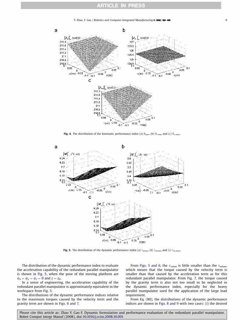
The distribution of the kinematic performance index is shownin Fig. 4 when the pose of the moving platform arefx ¼ fy ¼ fz ¼ 0 and z ¼ z0.
It is shown from Fig. 4(b) that the translational capability ofthe redundant parallel manipulator is equivalent in the investi-gated small workspace. It is consistent with the practical case.From Fig. 4(c), the difference between the maximum andminimum of the performance distribution in the workspace isvery small. In a sense of engineering, the rotational capability ofthe redundant parallel manipulator is approximately equivalent inthe workspace.
5 6 7 8
�0.400000 �0.400000 �2.000000 �2.000000
�2.000000 �2.000000 �0.400000 0.400000
1.500000 1.500000 1.500000 1.500000
0�uvw (m)
5 6 7 8
0.400000 �0.400000 �0.681000 �0.681000
�0.681000 �0.681000 �0.400000 0.400000
�0.037500 �0.037500 �0.037500 �0.037500
d performance evaluation of the redundant parallel manipulator.
ARTICLE IN PRESS
Fig. 4. The distribution of the kinematic performance index (a) _ymax, (b) _yv max and (c) _yo max.
Fig. 5. The distribution of the dynamic performance index (a) tamax, (b) tavmax and (c) taomax.
Y. Zhao, F. Gao / Robotics and Computer-Integrated Manufacturing ] (]]]]) ]]]–]]] 9
The distribution of the dynamic performance index to evaluatethe acceleration capability of the redundant parallel manipulatoris shown in Fig. 5, when the pose of the moving platform arefx ¼ fy ¼ fz ¼ 0 and z ¼ z0.
In a sense of engineering, the acceleration capability of theredundant parallel manipulator is approximately equivalent in theworkspace from Fig. 5.
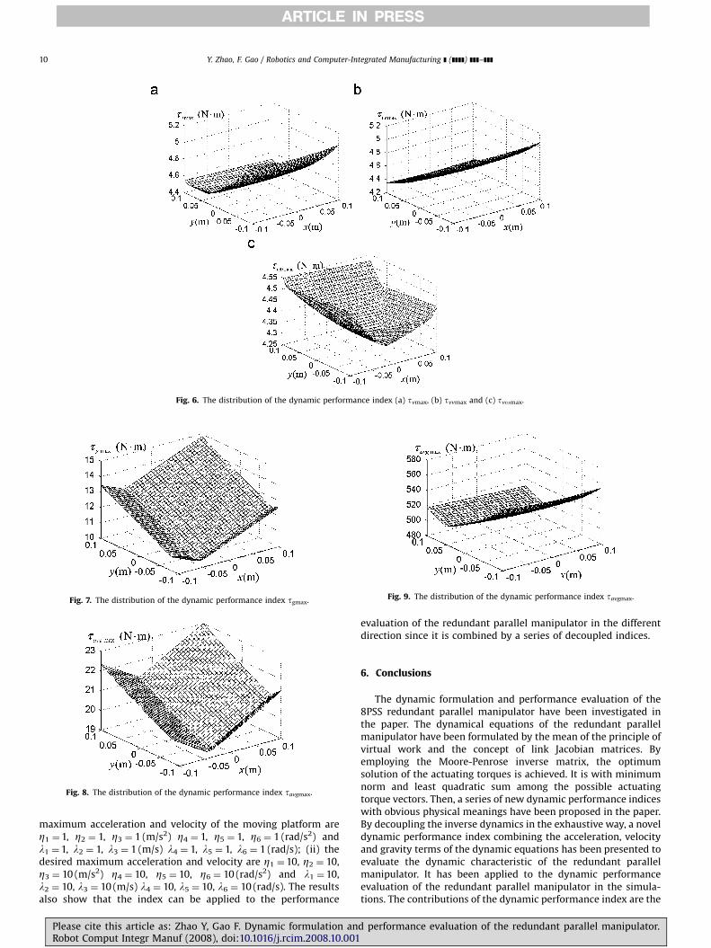
The distributions of the dynamic performance indices relativeto the maximum torques caused by the velocity term and thegravity term are shown in Figs. 6 and 7.
Please cite this article as: Zhao Y, Gao F. Dynamic formulation andRobot Comput Integr Manuf (2008), doi:10.1016/j.rcim.2008.10.001
From Figs. 5 and 6, the tvmax is little smaller than the tamax,which means that the torque caused by the velocity term issmaller than that caused by the acceleration term as for thisredundant parallel manipulator. From Fig. 7, the torque causedby the gravity term is also not too small to be neglected inthe dynamic performance index, especially for the heavyparallel manipulator used for the application of the large loadrequirement.
From Eq. (80), the distributions of the dynamic performanceindices are shown in Figs. 8 and 9 with two cases: (i) the desired
performance evaluation of the redundant parallel manipulator.
ARTICLE IN PRESS
Fig. 6. The distribution of the dynamic performance index (a) tvmax, (b) tvvmax and (c) tvomax.
Fig. 7. The distribution of the dynamic performance index tgmax.
Fig. 8. The distribution of the dynamic performance index tavgmax.
Fig. 9. The distribution of the dynamic performance index tavgmax.
Y. Zhao, F. Gao / Robotics and Computer-Integrated Manufacturing ] (]]]]) ]]]–]]]10
maximum acceleration and velocity of the moving platform areZ1 ¼1, Z2 ¼ 1, Z3 ¼ 1 (m/s2) Z4 ¼ 1, Z5 ¼ 1, Z6 ¼ 1 (rad/s2) andl1 ¼1, l2 ¼ 1, l3 ¼ 1 (m/s) l4 ¼ 1, l5 ¼ 1, l6 ¼ 1 (rad/s); (ii) thedesired maximum acceleration and velocity are Z1 ¼10, Z2 ¼ 10,Z3 ¼ 10 (m/s2) Z4 ¼ 10, Z5 ¼ 10, Z6 ¼ 10 (rad/s2) and l1 ¼10,l2 ¼ 10, l3 ¼ 10 (m/s) l4 ¼ 10, l5 ¼ 10, l6 ¼ 10 (rad/s). The resultsalso show that the index can be applied to the performance
Please cite this article as: Zhao Y, Gao F. Dynamic formulation anRobot Comput Integr Manuf (2008), doi:10.1016/j.rcim.2008.10.001
evaluation of the redundant parallel manipulator in the differentdirection since it is combined by a series of decoupled indices.
6. Conclusions
The dynamic formulation and performance evaluation of the8PSS redundant parallel manipulator have been investigated inthe paper. The dynamical equations of the redundant parallelmanipulator have been formulated by the mean of the principle ofvirtual work and the concept of link Jacobian matrices. Byemploying the Moore-Penrose inverse matrix, the optimumsolution of the actuating torques is achieved. It is with minimumnorm and least quadratic sum among the possible actuatingtorque vectors. Then, a series of new dynamic performance indiceswith obvious physical meanings have been proposed in the paper.By decoupling the inverse dynamics in the exhaustive way, a noveldynamic performance index combining the acceleration, velocityand gravity terms of the dynamic equations has been presented toevaluate the dynamic characteristic of the redundant parallelmanipulator. It has been applied to the dynamic performanceevaluation of the redundant parallel manipulator in the simula-tions. The contributions of the dynamic performance index are the
d performance evaluation of the redundant parallel manipulator.

ARTICLE IN PRESS
Y. Zhao, F. Gao / Robotics and Computer-Integrated Manufacturing ] (]]]]) ]]]–]]] 11
following: (i) it combines the acceleration, velocity and gravityterms of the dynamic equations to evaluate the dynamiccharacteristic of the redundant parallel manipulator; (ii) itevaluates the dynamic characteristic of the redundant parallelmanipulator by combining a series of decoupled indices, so itmakes it possible to control the performance index of theredundant parallel manipulator in the different direction bydynamic optimum design. The dynamic performance index isgeneral and can be used for the dynamic performance evaluationof other types of the parallel manipulators.
Future investigation will be paid on the dynamic optimumdesign of the redundant parallel manipulator by adopting thepresented indices. However, these related issues will be addressedby separate papers.
Acknowledgments
This research is sponsored by the China Postdoctoral ScienceFoundation (Grant no. 20070410719). We would also like to thankthe anonymous reviewers for their very useful comments.
References
[1] Merlet JP. Parallel robots. 2nd ed. Dordrecht: Kluwer Academic Publishers;2005.
[2] Tsai LW. Robot analysis, the mechanics of serial and parallel manipulators.New York: Wiley; 1999.
[3] Huang Z, Fang YF, Kong LF. Theory of parallel robotic mechanisms and control(in Chinese). Beijing: China Machine Press; 1997.
[4] Kim J, Park FC, Ryu SJ. Design and analysis of a redundantly actuated parallelmechanism for rapid machining. IEEE Trans Robotics Automat 2001;17(4):423–34.
[5] Merlet JP. Redundant parallel manipulators. Lab Robotics Autom. 1996;8(1):17–24.
[6] Nokleby SB, Fisher R, Podhorodeski RP. Force capabilities of redundantlyactuated parallel manipulators. Mech Mach Theory 2005;40(5):578–99.
[7] Wang J, Gosselin CM. Kinematic analysis and design of kinematicallyredundant parallel mechanisms. ASME J Mech Des 2004;126(1):109–18.
[8] Cheng H, Yiu YK, Li ZX. Dynamics and control of redundantly actuated parallelmanipulators. IEEE Trans Mechatronics 2003;8(4):483–91.
[9] Huang Z, Kong XW. Kinematic analysis on the spatial parallel mechanismswith redundant degree of freedom. Chin J Mech Eng 1995;31(3):44–50.
[10] Muller A. Internal preload control of redundantly actuated parallel manip-ulators—its application to backlash avoiding control. IEEE Trans Robotics2005;21(4):668–77.
[11] Mohamed MG, Gosselin CM. Design and analysis of kinematically redundantparallel manipulators with configurable platforms. IEEE Trans Robotics2005;21(3):277–87.
[12] Ebrahimi I, Carretero JA, Boudreau R. 3-PRRR redundant planar parallelmanipulator: inverse displacement, workspace and singularity analyses.Mech Mach Theory 2007;42(8):1007–16.
[13] Zanganeh KE, Angeles J. Mobility and position analyses of a novel redundantparallel manipulator. In: Proceeding of the IEEE international conference onrobotics and automation, California, USA, 1994. p. 3049–54.
[14] Merlet JP. Parallel robot: open problems. /http://www-sop.inria.fr/coprin/equipe/merlet/merlet_eng.htmlS, 1999.
[15] Merlet JP. Still a long way to go on the road for parallel mechanisms. /http://www-sop.inria.fr/coprin/equipe/merlet/merlet_eng.htmlS, 2002.
[16] Salisbury JK, Graig JJ. Articulated hands: force control and kinematic issues.Int J Robotics Res 1982;1(1):4–17.
[17] Angeles J, Rojas A. Manipulator kinematic inversion via condition-numberminimization and continuation. Int J Robotics Automat 1987;2(2):61–9.
[18] Angeles J, Lopez-Cajun CS. Kinematic isotropy and the conditioning index ofserial robotic manipulators. Int J Robotics Res 1992;11(6):560–71.
[19] Gosselin CM, Angeles J. The optimum kinematic design of a planar three-degree-of-freedom parallel manipulators. J Mech Trans Autom Des 1988;110(1):35–41.
[20] Gosselin CM, Angeles J. The optimum kinematic design of a spherical threedegree-of-freedom parallel manipulator. J Mech Trans Autom Des 1989;111(2):202–7.
[21] Gosselin CM, Angeles J. A global performance index for the kinematicoptimization of robotic manipulators. ASME J Mech Des 1991;113(3):220–6.
[22] Lipkin H, Duffy J. Hybrid twist and wrench control for a robotic manipulator.J Mech Trans Autom Des 1988;110(6):138–44.
[23] Doty KL, Melchiorri C, Bonevento C. A theory of generalized inverse applied torobotics. Int J Robotics Res 1993;12(1):1–19.
[24] Doty KL, Melchiorri C, Schwartz EM, et al. Robot manipulability. IEEE TransRobotics Autom 1995;11(3):462–8.
Please cite this article as: Zhao Y, Gao F. Dynamic formulation andRobot Comput Integr Manuf (2008), doi:10.1016/j.rcim.2008.10.001
[25] Gosselin CM. Dexterity indices for planar and spatial robotic manipulators.In: Proceedings of the IEEE international conference on robotics andautomation, Cincinnati, USA, 1990. p. 650–5.
[26] Pond G, Carretero JA. Formulating Jacobian matrices for the dexterity analysisof parallel manipulators. Mech Mach Theory 2006;41(9):1505–19.
[27] Altuzarra O, Salgado O, Petuya V, et al. Point-based Jacobian formulation forcomputational kinematics of manipulators. Mech Mach Theory 2006;41(12):1407–23.
[28] Kim SG, Ryu J. New dimensionally homogeneous Jacobian matrix formulationby three end-effector points for optimal design of parallel manipulators. IEEETrans Robotics Autom 2003;19(4):731–7.
[29] Yoshikawa T. Manipulability of robotic mechanisms. Int J Robotics Res1985;4(2):3–9.
[30] Yoshikawa T. Translational and rotational manipulability of robotic manip-ulators. In: Proceedings of the American control conference, San Diego, USA,1991. p. 1070–5.
[31] Hong KS, Kim JG. Manipulability analysis of a parallel machine tool:application to optimal link length design. J Robotics Syst 2000;17(8):403–15.
[32] Harib K, Srinivasan K. Kinematic and dynamic analysis of Stewart platform-based machine tool structures. Robotica 2003;21(5):541–54.
[33] Riebe S, Ulbrich H. Modelling and online computation of the dynamics of aparallel kinematic with six degrees-of-freedom. Arch Appl Mech 2003;72(11–12):817–29.
[34] Carvalho JCM, Ceccarelli M. A closed-form formulation for the inversedynamics of a Cassino parallel manipulator. Multibody Syst Dyn 2001;5(2):185–210.
[35] Dasgupta B, Mruthyunjaya TS. Closed-form dynamic equations of the Stewartplatform through the Newton-Euler approach. Mech Mach Theory1998;33(7):993–1012.
[36] Dasgupta B, Mruthyunjaya TS. A Newton-Euler formulation for the inversedynamics of the Stewart platform manipulator. Mech Mach Theory 1998;33(8):1135–52.
[37] Khalil W, Guegan S. A novel solution for the dynamic modeling ofGough–Stewart manipulators. In: Proceeding of the IEEE internationalconference on robotics and automation, Washington, USA, 2002. p. 817–22.
[38] Do WQD, Yang DCH. Inverse dynamic analysis and simulation of a platformtype of robot. J Robotics Syst 1988;5(53):209–27.
[39] Ji Z. Study of the effect of leg inertia in Stewart platform. In: Proceeding of theIEEE international conference on robotics and automation, Atlanta, USA, 1993.p. 212–26.
[40] Khalil W, Guegan S. Inverse and direct dynamic modeling of Gough–Stewartrobots. IEEE Trans Robotics 2004;20(4):755–61.
[41] Dasgupta B, Choudhury P. A general strategy based on the Newton-Eulerapproach for the dynamic formulation of parallel manipulators. Mech MachTheory 1999;34(6):801–24.
[42] Lee SS, Lee JM. Design of a general purpose 6-DOF haptic interface.Mechatronics 2003;13(7):697–722.
[43] Lee KM, Shan DK. Dynamic analysis of a three-degrees-of-freedom in-parallelactuated manipulator. IEEE Trans Robotics Autom 1988;4(3):361–7.
[44] Lee J, Albus J, Dagalakis NG, et al. Computer simulation of a parallel linkmanipulator. Robotics Comput Integrated Manuf 1989;5(3):333–42.
[45] Pang H, Shahinpoor M. Inverse dynamics of a parallel manipulator. J RoboticsSyst 1994;11(8):693–702.
[46] Geng Z, Haynes LS, Lee TD, Carroll RL. On the dynamic and kinematic analysisof a class of Stewart platform. Robotics Autonomous Syst 1992;9(4):237–54.
[47] Lebret G, Liu K, Lewis FL. Dynamic analysis and control of a Stewart platformmanipulator. J Robotics Syst 1993;10(5):629–55.
[48] Miller K, Clavel R. The lagrange-based model of delta-4 robot dynamics, vol. 8.Berlin: Springer; 1992 [Robotersysteme (4), p. 49–54].
[49] Ben-Horin R, Shoham M, Djerassi S. Kinematics, dynamics and construction ofa planarly actuated parallel robot. Robotics Comput Integrated Manuf 1998;14(2):163–72.
[50] Liu MJ, Li CX, Li CN. Dynamics analysis of the Gough–Stewart platformmanipulator. IEEE Trans Robotics Autom 2000;16(1):94–8.
[51] Li M, Huang T, Mei JP, et al. Dynamic formulation and performancecomparison of the 3-DOF modules of two reconfigurable PKMs—theTriVariant and the Tricept. ASME J Mech Des 2005;127(6):1129–36.
[52] Sokolov A, Xirouchakis P. Dynamics analysis of a 3-DOF parallel manipulatorwith R–P–S joint structure. Mech Mach Theory 2007;42(5):541–57.
[53] Caccavale F, Siciliano B, Villani L. The tricept robot: dynamics and impedancecontrol. IEEE/ASME Trans Mechatronics 2003;8(2):263–8.
[54] Wang J, Gosselin CM. A new approach for the dynamic analysis of parallelmanipulators. Multibody Syst Dyn 1998;2(3):317–34.
[55] Stefan S, Laurian S, Radu R. Inverse dynamics of Star parallel manipulator. In:Proceedings of the IEEE international conference on control applicationsTaipei, Taiwan, 2004. p. 333–7.
[56] Tsai LW. Solving the inverse dynamics of a Stewart–Gough manipulator bythe principle of virtual work. ASME J Mech Des 2000;122(1):3–9.
[57] Zhu ZQ, Li JS, Gan ZX, Zhang H. Kinematic and dynamic modelling for real-time control of Tau parallel robot. Mech Mach Theory 2005;40(9):1051–67.
[58] Codourey A. Dynamic modeling of parallel robots for computed-torquecontrol implementation. Int J Robotics Res 1998;17(2):1325–36.
[59] Codourey A, Burdet E. A body oriented method for finding a linear form of thedynamic equations of fully parallel robot. In: Proceeding of the IEEEinternational conference on robotics and automation, Albuquerque, USA,1997. p. 1612–8.
performance evaluation of the redundant parallel manipulator.

ARTICLE IN PRESS
Y. Zhao, F. Gao / Robotics and Computer-Integrated Manufacturing ] (]]]]) ]]]–]]]12
[60] Zhao YJ, Yang ZY, Huang T. Inverse dynamics of Delta robot based on theprinciple of virtual work. Trans Tianjin Univ 2005;11(4):268–73.
[61] Staicu S, Carp-Ciocardia DC. Dynamic analysis of Clavel’s delta parallel robot.In: Proceedings of the IEEE international conference on robotics andautomation, Taipei, Taiwan, 2003. p. 4116–21.
[62] Zhang CD, Song SM. An effective method for inverse dynamics manipulatorsbased upon virtual work principle. J Robotics Syst 1993;10(5):605–27.
[63] Gallardo J, Rico JM, Frisoli A. Dynamics of parallel manipulators by means ofscrew theory. Mech Mach Theory 2003;38(11):1113–31.
[64] Muller A, Maiber P. A Lie-group formulation of kinematics and dynamics ofconstrained MBS and its application to analytical mechanics. Multibody SystDyn 2003;9(4):311–52.
[65] Khan WA, Krovi VA, Saha SK, Angeles J. Recursive kinematics and inversedynamics for a planar 3R parallel manipulator. ASME J Dyn Syst Meas Control2005;127(4):529–36.
[66] Koteswara Rao AB, Saha SK, Rao PVM. Dynamics modelling of hexaslidesusing the decoupled natural orthogonal complement matrices. MultibodySyst Dyn 2006;15(2):159–80.
[67] Xi FF, Angelico O, Sinatra R. Tripod dynamics and its inertia effect. ASME JMech Des 2005;127(1):144–9.
[68] Lee MK, Park KW. Kinematics and dynamics analysis of a double parallelmanipulator for enlarging workspace and avoiding singularities. IEEE TransRobotics Autom 1999;15(6):1024–34.
[69] Sugimoto K. Kinematics and dynamic analysis of parallel manipulator bymeans of motor algebra. ASME J Mech Trans Autom Des 1987;109(1):3–7.
[70] Geike T, McPhee J. Inverse dynamic analysis of parallel manipulators with fullmobility. Mech Mach Theory 2003;38(6):549–62.
[71] McPhee J, Shi P, Piedboeuf JC. Dynamics of multibody systems using virtualwork and symbolic programming. Math Comput Modelling Dynamical Syst2002;8(3):137–55.
[72] Selig JM, McAree PR. Constrained robot dynamics II: parallel machines.J Robotics Syst 1999;16(9):487–98.
[73] Gosselin CM. Parallel computational algorithms for the kinematics anddynamics of planar and spatial parallel manipulators. ASME J Dyn Syst MeasControl 1996;118(1):22–8.
[74] Wiens GJ, Shamblin SA, Oh YH. Characterization of PKM dynamics in terms ofsystem identification. Proc Inst Mech Eng Part K: J Multi-body Dyn 2002;216:59–72.
[75] Yiu YK, Cheng H, Xiong ZH, et al. On the dynamics of parallel manipulators.In: Proceeding of the IEEE international conference on robotics andautomation, Seoul, Korea, 2001. p. 3766–71.
Please cite this article as: Zhao Y, Gao F. Dynamic formulation anRobot Comput Integr Manuf (2008), doi:10.1016/j.rcim.2008.10.001
[76] Huang Q, Hadeby H, Sohlenius G. Connection method for dynamic modellingand simulation of parallel kinematic mechanism (PKM) machines. Int J AdvManuf Technol 2002;19(3):163–73.
[77] Kemal Ider S. Inverse dynamics of parallel manipulators in the presence ofdrive singularities. Mech Mach Theory 2005;40(1):33–44.
[78] Ma O, Angeles J. The concept of dynamics isotropy and its applications toinverse kinematics and trajectory planning. In: Proceedings of the IEEEinternational conference on robotics and automation, Cincinnati, USA, 1990.p. 481–6.
[79] Ma O, Angeles J. Optimum design of manipulators under dynamic isotropyconditions. In: Proceedings of the IEEE international conference on roboticsand automation, Atlanta, USA, 1993. p. 470–5.
[80] Asada H. A geometrical representation of manipulator dynamics and itsapplication to arm design. ASME J Dyn Syst Meas Control 1983;105(3):131–5.
[81] Asada H. Dynamic analysis and design of robot manipulators using inertiaellipsoids. In: Proceedings of the IEEE international conference on roboticsand automation, Atlanta, USA, 1984. p. 94–102.
[82] Yoshikawa T. Dynamic manipulability of robot manipulators. J Robotics Syst1985;2(1):113–24.
[83] Huang T, Mei JP, Li ZX. A method for estimating servomotor parameters of aparallel robot for rapid pick-and-place operations. ASME J Mech Des 2005;127(7):596–601.
[84] Chiacchio P, Concilio M. The dynamics manipulability ellipsoid for redundantmanipulators. In: Proceedings of the IEEE international conference onrobotics and automation, Leuven, Belgium, 1998. p. 95–100.
[85] Chiacchio P, Chiaverini S, Sciavicco L. Reformulation of dynamic manipul-ability ellipsoid for robotic manipulators. In: Proceedings of the IEEEinternational conference on robotics and automation, California, USA, 1991.p. 2192–7.
[86] Park FC, Kim JW. Manipulability of closed kinematic chains. ASME J Mech Des1998;120(4):542–8.
[87] Gregorio RD, Parenti-Castelli V. Dynamic performance characterization of3-DOF parallel manipulators. In: Lenarcic J, Thomas F, editors. Advances inrobot kinematics: theory and applications. Netherlands: Kluwer AcademicPublishers; 2002. p. 11–20.
[88] Merlet JP. Jacobian, Manipulability, condition number, and accuracy ofparallel robots. ASME J Mech Des 2006;128(1):199–206.
[89] Huang T, Li M, Li ZX, Chetwynd DG, Whitehouse DJ. Optimal kinematicdesign of 2-DOF parallel manipulators with well-shaped workspace boundedby a specified conditioning index. IEEE Trans Robotics Autom 2004;20(3):538–43.
d performance evaluation of the redundant parallel manipulator.