Dynamic Directional System for the Visually Impaired ENSC 340 Project Copyright 2003 © Sound...
44
Dynamic Directional System for the Visually Impaired ENSC 340 Project Copyright 2003 © Sound Directions
-
date post
19-Dec-2015 -
Category
Documents
-
view
220 -
download
1
Transcript of Dynamic Directional System for the Visually Impaired ENSC 340 Project Copyright 2003 © Sound...

Dynamic Directional System for the Visually Impaired
ENSC 340 Project
Copyright 2003 © Sound Directions

Team Organization
• Farhan Ali, Team leader, CEO
• Daniel Kim, VP R&D
• Nima Jahedi, CTO
• Galerah Paradian, VP Marketing
• Ted Liu, CFO
• Chris Chun, COO

Overview
• Market
• Solutions
• Phase one details
• Phase two details
• Questions

The Need
• 105,000 Canadians registered with CNIB
• Number is increasing by one thousand people per month
• Navigation aids very limited

Existing Solutions
• Guide Dogs
• Talking Signs™
– IR Beacons placed in environment
– User Must Scan using hand-held device
– Line of sight required
– No directions given

Dynamic Directional System
• Provide directions to the visually impaired based on their orientation
• Easy to use for the visually impaired
• Effective in indoor and outdoor environments
• Cheap
Research
• Visually Impaired Program at VCC
– Focus group of visually impaired navigation students
• CNIB
– Existing trends and technologies

Project Overview
• Phase One
– ENSC 340 deliverable
– Basic functionality
• Phase Two
– End of 2004

Phase One Overview
USER MODULE:“Snow hill is North, Civic
centre is East”
Location code
Sign Module

Phase One Overview (Contd..)
Database

Wireless Communications Technology
• Wireless Communications Design criteria:
– Simple to integrate
– Short-range (within a 5 ~ 7 meter radii)
– Does not require line-of-sight
– Cheap

Competing Technologies
• Infrared Pros
• Cheap, simple to integrate
– Cons• Needs line-of-sight
• Narrow range communication
• Ultrasound– Cons
• Complicated detection scheme
• Only useful in range finding
• Discouraged by instructors

Competing Technologies (Contd..)
• Bluetooth
Pros• For short-range
application
– Cons• Takes time to develop
• Expensive, development kit costs > $1,000 apiece
• RF Pros
• Higher S/N
• Not line-of-sight
• Simple to use
– Cons
• Co-channel Interference

Technology of our choice
• Linx Technologies ES-series Evaluation Kit
– Cheapest module
– Allows surface mount
• Low interference and better S/N ratio
• Power consumption
• Signal strength indicator
• Usage of unlicensed ISM-band
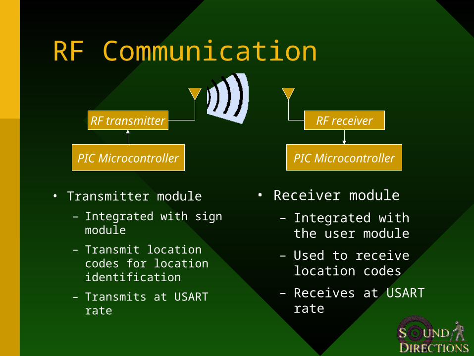
RF Communication
• Receiver module
– Integrated with the user module
– Used to receive location codes
– Receives at USART rate
• Transmitter module
– Integrated with sign module
– Transmit location codes for location identification
– Transmits at USART rate
RF transmitter
PIC Microcontroller
RF receiver
PIC Microcontroller

Modules Specification
Transmission Frequency
916.48MHz
Interface USART serial with header encapsulation
Data Rate Up to 200 ~ 56,000bps
Range Approx. 500ft indoor

Range Determination
• To determine if the user is near a sign
• When the user is near a sign– Notifies the user
– Receives location codes
• When the user is not near a sign– Warns the user

Range Control System
• When RSSI is low• The Processor is sleeping
– Saves Power– No UART
• When RSSI is high• Interrupt
• The Processor wakes up
Antenna
ReceiverModule
SignalProcessing
PICRSSI916MHz FSK
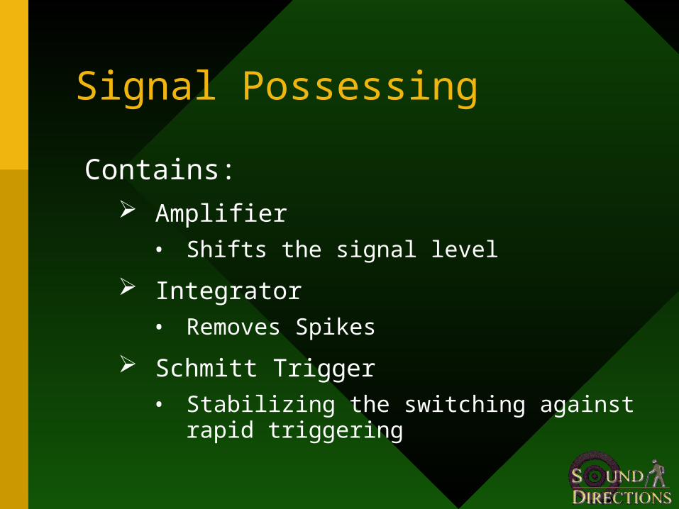
Signal Possessing
Contains: Amplifier
• Shifts the signal level
Integrator
• Removes Spikes
Schmitt Trigger
• Stabilizing the switching against rapid triggering

Advantages
• Processor goes to sleep
– Saves Power
– Extends Battery Life
– Reduces interference from other RF sources
– Ensures data is only received near a sign

UART
• Universal Asynchronous Receiver and Transmitter
• Data communication between microcontrollers and RF receiver/transmitter
• Frame Format: (11bits)– 8-bits Data– Even Parity
ParityBit
8-Bit DataSTART Stop

PIC16F876A UART
- Two level FIFO register
- Used for Preamble and Location Code
- Error Flags (OERR, FERR)
- Baud rate generator

Transmission
• We are using 33.6K Baud
• Transmit Preamble and Data periodically
• Produce and send “Parity bit”
WAIT
SEND DATA
SEND PREAMBLE
Transmitter

Reception
• After Microcontroller wakes up:
– Check for errors
– Check for Data validity
Check Parity
OERR Check
FERRCheck
Wait for a sign
Receive Data + parity
Error
Error
Error
Good data
Good data
Receiver
Good data

Reception (Contd..)
Preamble?
Old Data?
Valid Data?
Received Data
Error
Error
Enable location code rx
Good data
• After receiving one byte of data:
– Check if it is the preamble
– Check if it is old data
– Check if it is valid data

Error Checking
1) Parity (Error in transmission)
- Done internally by the microcontroller firmware
- Calculate Parity in Transmitter side- Check for parity bit on the Receiver side
Single bit checking had been used to Parity detection
Errors
Parity OERR FERR

Error Checking (Contd..)
2) Internal PIC microcontroller error flags for UART
-OERR (Overrun error)
Third byte arrives before reading the last two
-FERR (Framing error)
Stop bit detected as clear
PIC will reject data with any of the errors.

Data processing
Determine orientation
Calculate resultant direction
Wait for valid location code
SPEAK
Fetch store namesfrom database
Same code?Yes

Determining orientationNorth
South
West East
00 32
64
96
128
160
192
224
0 1 1 0 0 01 1

Determine resultant direction
Resultant direction =
Store Direction – User direction
Ex) London Drugs – South (126)
User orientation – East (64)
126 - 64 = 64 EAST

Compass
• Provides digital 0-255 compass bearing
• Uses Philips magnetic field sensor
• Can detect Earth’s magnetic field

Limitations
• Magnetic interference
– may influence compass reading
– compass should be kept afar
– choose sign locations with care
• Tilting
– tilting off horizontal results in increasing error
– Tilt compensated compass (upto 50˚ without error)

Text-to-speech
• Input: ASCII characters
• Converts ASCII characters to speech
• Reduces storage, complexity and cost

I2C
• Bi-directional two-wire serial bus
• provides a communication link between integrated circuits (ICs)
Compass bearings
ASCII

Phase Two Overview
• Data Storage
• User Interface
• Potential

Data Storage
Database
Internet
Database

Proposed System
Internet
Sign Module
Sign Module
Server with directional database
Location Codes
Directions

Internet storage
• Can store large amounts of data
• Easier to update the database
• Infrastructure already in place
• Cheap to implement, can be used with other applications

Internet Integration
• PDA with WLAN card Easy to program
Minimal Hardware design required
– Visually impaired people have no other use for PDA
• Cell Phone Used by many people
– Slower Data rates
– Coverage Issues
Internet Integration (Contd..)
• Custom made WLAN moduleCould be made cheaper
Customized for use by visually impaired people
– Extensive Hardware development required
User Interface
• Hot Keys for critical locations
• Earphone
• Pushbuttons with Braille subtitles

Complete Solution
• To accurately direct visually impaired people to any place they wish to go

Budget
Phase One Phase Two
Estimated Actual Estimated
$850 $550 $2000

Summary
• Phase One completed
• Research on phase two underway already
– Orientation Detection Methods
– Communication methods
– User Interface


![SMART CANE FOR VISUALLY IMPAIRED PEOPLEgreenskill.net/suhailan/fyp/report/037454.pdf · visually-impaired people. First, Smart Cane: Assistive Cane for Visually-impaired People [9].](https://static.fdocuments.us/doc/165x107/5fc7e53d210a4218aa7c699a/smart-cane-for-visually-impaired-visually-impaired-people-first-smart-cane-assistive.jpg)