Dynamic deadlock verification r t i f a ct * C o m ple t e...
13
C o n s i s t e n t * C o m p le t e * W e l l D o c u m e n t e d * E a s y t o R e u s e * * E va l u a t e d * P o P * A r t i f a c t * A E C P P Dynamic deadlock verification for general barrier synchronisation Tiago Cogumbreiro Imperial College London Raymond Hu Imperial College London Francisco Martins University of Lisbon Nobuko Yoshida Imperial College London Abstract We present Armus, a dynamic verification tool for deadlock detec- tion and avoidance specialised in barrier synchronisation. Barriers are used to coordinate the execution of groups of tasks, and serve as a building block of parallel computing. Our tool verifies more bar- rier synchronisation patterns than current state-of-the-art. To im- prove the scalability of verification, we introduce a novel event- based representation of concurrency constraints, and a graph-based technique for deadlock analysis. The implementation is distributed and fault-tolerant, and can verify X10 and Java programs. To formalise the notion of barrier deadlock, we introduce a core language expressive enough to represent the three most widespread barrier synchronisation patterns: group, split-phase, and dynamic membership. We propose a graph analysis technique that selects from two alternative graph representations: the Wait-For Graph, that favours programs with more tasks than barriers; and the State Graph, optimised for programs with more barriers than tasks. We prove that finding a deadlock in either representation is equivalent, and that the verification algorithm is sound and complete with respect to the notion of deadlock in our core language. Armus is evaluated with three benchmark suites in local and distributed scenarios. The benchmarks show that graph analysis with automatic graph-representation selection can record a 7-fold execution increase versus the traditional fixed graph representation. The performance measurements for distributed deadlock detection between 64 processes show negligible overheads. Categories and Subject Descriptors D.4.1 [Process Manage- ment]: Deadlocks—detection, avoidance; D.3.3 [Language Con- structs and Features]: Concurrent programming structures—bar- riers, phasers; F.3.2 [Semantics of Programming Languages]: Op- erational semantics General Terms Verification Keywords barrier synchronisation, phasers, deadlock detection, deadlock avoidance, X10, Java 1. Introduction The rise of multicore processors has pushed mainstream program- ming languages to incorporate various parallel programming and concurrency features. An important class of these are barriers and their associated techniques. Java 5–8 and .NET 4 introduced several abstractions that expose barriers explicitly or otherwise use implicit barrier synchronisations: latches, cyclic barriers, fork/join, futures, and stream programming. The basic functionality of a barrier is to coordinate the execution of a group of tasks: it allows them to wait for each other at an execution point. Recent languages feature more advanced abstractions, such as clocks in X10 [45] and phasers in Habanero-Java/C (HJ) [7], that support highly dynamic coordi- nation of control flow and synchronisations. In particular, phasers unify the barrier synchronisation patterns available in Java, X10, and .NET under a single abstraction. As for many other concurrency mechanisms, deadlocks—in which two tasks blocked on distinct barriers are (indirectly) wait- ing for each other—are one of the primary errors related to bar- rier synchronisation. Historically, the approach to counter barrier deadlocks has been to restrict the available barrier synchronisation patterns such that programs are barrier-deadlock free by construc- tion, e.g., OpenMP [30] restricts barrier composition to syntactic nesting. To date there are no available tools for barrier-deadlock verification in X10 or HJ, nor for mainstream libraries, such as the Java Phaser [16] and the .NET Barrier [25] APIs. Two key characteristics exacerbate barrier-deadlock verifica- tion in recent languages and systems: barriers can be created dy- namically and communicated among tasks as values (called first- class barriers [41]); and the group of participants can change over time (dynamic membership [29]). Due to the difficulty of statically analysing the usage of first-class barriers (e.g., dealing with aliases and non-determinism statically), the state-of-the-art in barrier-deadlock verification is based on dynamic techniques that monitor the run-time execution of programs (existing tools for static verification handle only a simplistic model where synchro- nisation is global; see Section 7). Dynamic membership, found in Java, .NET, X10, and HJ, is, however, simply not handled by any existing barrier-deadlock verification tools. The state-of-the-art in dynamic barrier-deadlock verification follows graph-based techniques and originates from MPI [28] and UPC [42]. Graph-based approaches work by maintaining a rep- resentation of the concurrency constraints between running tasks (e.g., the synchronisation state of blocked tasks), and by perform- ing a graph analysis on this state (e.g., cyclic dependencies). While the existing graph-based tools, such as [13, 14], precisely identify deadlocks in systems featuring multiple barriers, these approaches are too limited in the presence of dynamic membership. The main limitations of the current tools are: (i) a representa- tion of concurrency constraints that assumes static barrier mem- bership, and (ii) committing to the Wait-For Graph [20] analysis technique that is optimised for concurrency constraints with more tasks than barriers (a rare situation for classical parallel programs). Naive extensions to resolve (i) face the problem of maintaining the membership status of barriers consistently and efficiently; this is- sue is compounded in the distributed setting, which is a key design point of deadlock verification for languages like X10/HJ. Issue (ii) is related to the dynamic nature of such barrier applications, where the number of tasks and barrier synchronisations may not be known until run-time and may vary during execution. Committing to a par- ticular graph model can thus hinder the scalability of dynamic ver- ification. The State Graph [18] is an alternative model that favours scenarios with more tasks than barriers. In the general case we can- 1
Transcript of Dynamic deadlock verification r t i f a ct * C o m ple t e...
Consist
ent *Complete *
Well D
ocumented*Easyt
oR
euse* *
Evaluated
*PoP*
Art ifact *
AEC
PP
Dynamic deadlock verificationfor general barrier synchronisation
Tiago CogumbreiroImperial College London
Raymond HuImperial College London
Francisco MartinsUniversity of [email protected]
Nobuko YoshidaImperial College [email protected]
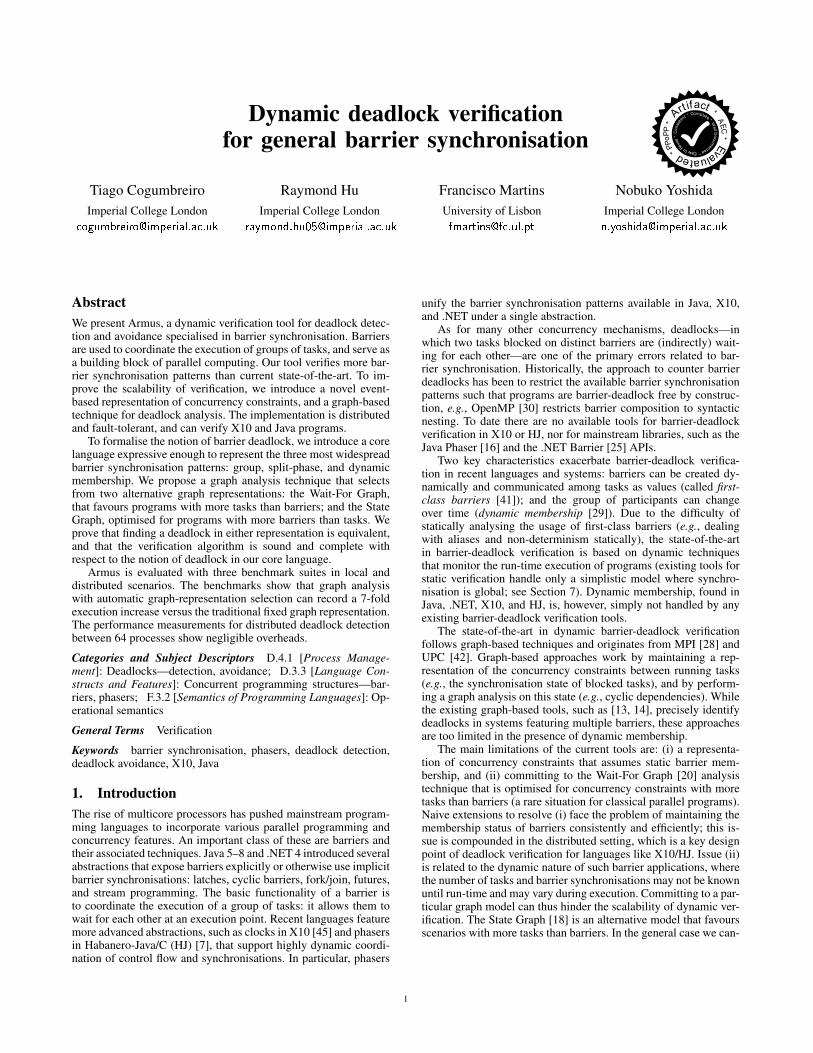
AbstractWe present Armus, a dynamic verification tool for deadlock detec-tion and avoidance specialised in barrier synchronisation. Barriersare used to coordinate the execution of groups of tasks, and serve asa building block of parallel computing. Our tool verifies more bar-rier synchronisation patterns than current state-of-the-art. To im-prove the scalability of verification, we introduce a novel event-based representation of concurrency constraints, and a graph-basedtechnique for deadlock analysis. The implementation is distributedand fault-tolerant, and can verify X10 and Java programs.
To formalise the notion of barrier deadlock, we introduce a corelanguage expressive enough to represent the three most widespreadbarrier synchronisation patterns: group, split-phase, and dynamicmembership. We propose a graph analysis technique that selectsfrom two alternative graph representations: the Wait-For Graph,that favours programs with more tasks than barriers; and the StateGraph, optimised for programs with more barriers than tasks. Weprove that finding a deadlock in either representation is equivalent,and that the verification algorithm is sound and complete withrespect to the notion of deadlock in our core language.
Armus is evaluated with three benchmark suites in local anddistributed scenarios. The benchmarks show that graph analysiswith automatic graph-representation selection can record a 7-foldexecution increase versus the traditional fixed graph representation.The performance measurements for distributed deadlock detectionbetween 64 processes show negligible overheads.
Categories and Subject Descriptors D.4.1 [Process Manage-ment]: Deadlocks—detection, avoidance; D.3.3 [Language Con-structs and Features]: Concurrent programming structures—bar-riers, phasers; F.3.2 [Semantics of Programming Languages]: Op-erational semantics
General Terms Verification
Keywords barrier synchronisation, phasers, deadlock detection,deadlock avoidance, X10, Java
1. IntroductionThe rise of multicore processors has pushed mainstream program-ming languages to incorporate various parallel programming andconcurrency features. An important class of these are barriers andtheir associated techniques. Java 5–8 and .NET 4 introduced severalabstractions that expose barriers explicitly or otherwise use implicitbarrier synchronisations: latches, cyclic barriers, fork/join, futures,and stream programming. The basic functionality of a barrier isto coordinate the execution of a group of tasks: it allows them towait for each other at an execution point. Recent languages featuremore advanced abstractions, such as clocks in X10 [45] and phasersin Habanero-Java/C (HJ) [7], that support highly dynamic coordi-nation of control flow and synchronisations. In particular, phasers
unify the barrier synchronisation patterns available in Java, X10,and .NET under a single abstraction.
As for many other concurrency mechanisms, deadlocks—inwhich two tasks blocked on distinct barriers are (indirectly) wait-ing for each other—are one of the primary errors related to bar-rier synchronisation. Historically, the approach to counter barrierdeadlocks has been to restrict the available barrier synchronisationpatterns such that programs are barrier-deadlock free by construc-tion, e.g., OpenMP [30] restricts barrier composition to syntacticnesting. To date there are no available tools for barrier-deadlockverification in X10 or HJ, nor for mainstream libraries, such as theJava Phaser [16] and the .NET Barrier [25] APIs.
Two key characteristics exacerbate barrier-deadlock verifica-tion in recent languages and systems: barriers can be created dy-namically and communicated among tasks as values (called first-class barriers [41]); and the group of participants can changeover time (dynamic membership [29]). Due to the difficulty ofstatically analysing the usage of first-class barriers (e.g., dealingwith aliases and non-determinism statically), the state-of-the-artin barrier-deadlock verification is based on dynamic techniquesthat monitor the run-time execution of programs (existing tools forstatic verification handle only a simplistic model where synchro-nisation is global; see Section 7). Dynamic membership, found inJava, .NET, X10, and HJ, is, however, simply not handled by anyexisting barrier-deadlock verification tools.
The state-of-the-art in dynamic barrier-deadlock verificationfollows graph-based techniques and originates from MPI [28] andUPC [42]. Graph-based approaches work by maintaining a rep-resentation of the concurrency constraints between running tasks(e.g., the synchronisation state of blocked tasks), and by perform-ing a graph analysis on this state (e.g., cyclic dependencies). Whilethe existing graph-based tools, such as [13, 14], precisely identifydeadlocks in systems featuring multiple barriers, these approachesare too limited in the presence of dynamic membership.
The main limitations of the current tools are: (i) a representa-tion of concurrency constraints that assumes static barrier mem-bership, and (ii) committing to the Wait-For Graph [20] analysistechnique that is optimised for concurrency constraints with moretasks than barriers (a rare situation for classical parallel programs).Naive extensions to resolve (i) face the problem of maintaining themembership status of barriers consistently and efficiently; this is-sue is compounded in the distributed setting, which is a key designpoint of deadlock verification for languages like X10/HJ. Issue (ii)is related to the dynamic nature of such barrier applications, wherethe number of tasks and barrier synchronisations may not be knownuntil run-time and may vary during execution. Committing to a par-ticular graph model can thus hinder the scalability of dynamic ver-ification. The State Graph [18] is an alternative model that favoursscenarios with more tasks than barriers. In the general case we can-
1
not determine which model is most suitable statically; moreover,this property may change as execution proceeds.
Armus This paper presents Armus, to our knowledge, the firstdeadlock verification tool for phasers [7, 34]. The contributions ofthis work are as follows.
• Armus leverages phasers to represent concurrency constraintsamong synchronisation events. This representation enables theanalysis of first-class barriers with dynamic membership, andsimplifies the algorithm of distributed deadlock detection.• Armus introduces a technique to improve the scalability of
graph-based verification, by automatically and dynamically se-lecting and transforming between the commonly used Wait-ForGraph (WFG) and the alternative State Graph (SG) models.• We formalise an operational model for a concurrent language
with phasers (subsuming the barriers of [16, 25, 45]) and theArmus deadlock verification algorithm. We show that our dead-lock verification is sound and complete with respect to thecharacterisation of deadlock in our language, and establish theWFG-SG equivalence.• The Armus-X10 and JArmus applications are the first deadlock
verification tools for X10 clocks and the Java phaser API, fea-turing: distributed deadlock detection where the tool reports ex-isting deadlocks, and local deadlock avoidance where the toolraises an exception before entering a deadlock.
To address (i), Armus introduces a novel representation of con-currency dependencies, based on events in the sense of Lamport’slogical clocks [22]. A major part of deadlock analysis is the genera-tion of concurrency constraints, attained by bookkeeping the statusof tasks and barriers. The insight of our technique is to interpretthe operation of waiting for a phase as observing a timestamp; andthen to assert a dependency from the phase a task is blocked toany (future) phase the task participates. With this representation Ar-mus simplifies the analysis of dynamic membership, since it avoidstracking the arrival and departure of participants on a synchroni-sation; bookkeeping the participants of a barrier in a distributedsetting is a global state, thus a challenging procedure to maintain.
Armus addresses (ii) with a novel technique that automaticallyselects between two graph models according to the monitored con-currency constraints. The standard graph model used in graph anal-ysis, the WFG, comes from distributed databases [20], a settingwith a fixed number of tasks and dynamic resource creation. TheWFG was therefore optimised for concurrency constraints withmany resources and few tasks. The underlying assumptions of theWFG no longer hold for languages with dynamic tasks and dy-namic barrier creation (first-class barriers), such as X10 and Java.For these applications, Armus proposes a technique that selects ei-ther the WFG or the SG depending on the ratio between tasks andbarriers. The difference on the size of the graph can be dramatic.For instance, in benchmark PS [46], the average edge count de-creases from 781 edges to 6 edges (see Section 6.3). The automaticmodel selection performs at least as fast as the usual approach of afixed graph representation.
We outline the sections of this paper. The following section il-lustrates the subtleties of barrier deadlock verification regardingfirst-class barriers with dynamic membership and how Armus ad-dresses these challenges, with connections to later sections. Sec-tion 3 presents a programming language abstraction (PL) for gen-eral barrier constructs, expressive enough to capture all surveyedbarrier synchronisation patterns. In Section 4, we introduce a novelrepresentation of barrier-dependency state based on synchronisa-tion events and define the construction of Wait-For Graphs andState Graphs for Armus deadlock verification. We show that theWFG and SG constructed from a given state are equivalent wrt.
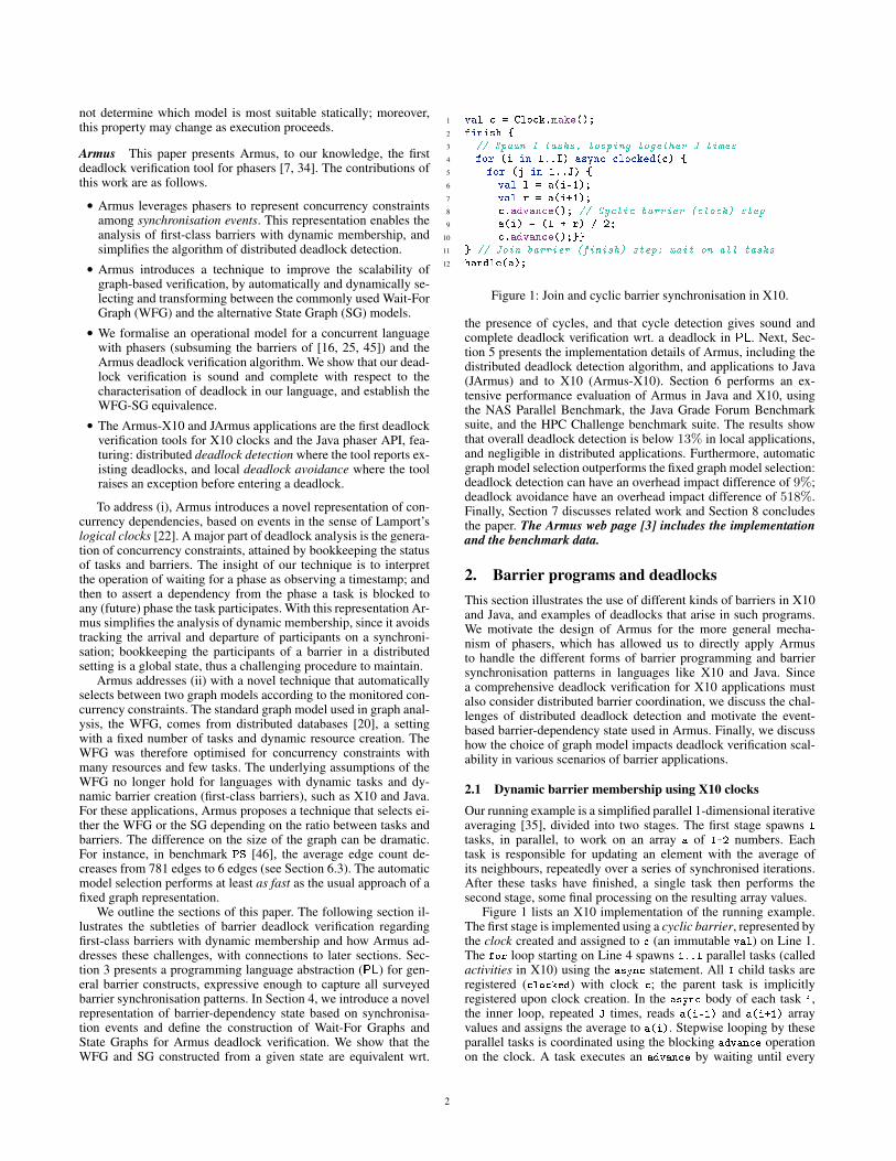
1 val c = Clock.make();2 finish {3 // Spawn I tasks, looping together J times4 for (i in 1..I) async clocked(c) {5 for (j in 1..J) {6 val l = a(i-1);7 val r = a(i+1);8 c.advance(); // Cyclic barrier (clock) step9 a(i) = (l + r) / 2;
10 c.advance();}}11 } // Join barrier (finish) step: wait on all tasks12 handle(a);
Figure 1: Join and cyclic barrier synchronisation in X10.
the presence of cycles, and that cycle detection gives sound andcomplete deadlock verification wrt. a deadlock in PL. Next, Sec-tion 5 presents the implementation details of Armus, including thedistributed deadlock detection algorithm, and applications to Java(JArmus) and to X10 (Armus-X10). Section 6 performs an ex-tensive performance evaluation of Armus in Java and X10, usingthe NAS Parallel Benchmark, the Java Grade Forum Benchmarksuite, and the HPC Challenge benchmark suite. The results showthat overall deadlock detection is below 13% in local applications,and negligible in distributed applications. Furthermore, automaticgraph model selection outperforms the fixed graph model selection:deadlock detection can have an overhead impact difference of 9%;deadlock avoidance have an overhead impact difference of 518%.Finally, Section 7 discusses related work and Section 8 concludesthe paper. The Armus web page [3] includes the implementationand the benchmark data.
2. Barrier programs and deadlocksThis section illustrates the use of different kinds of barriers in X10and Java, and examples of deadlocks that arise in such programs.We motivate the design of Armus for the more general mecha-nism of phasers, which has allowed us to directly apply Armusto handle the different forms of barrier programming and barriersynchronisation patterns in languages like X10 and Java. Sincea comprehensive deadlock verification for X10 applications mustalso consider distributed barrier coordination, we discuss the chal-lenges of distributed deadlock detection and motivate the event-based barrier-dependency state used in Armus. Finally, we discusshow the choice of graph model impacts deadlock verification scal-ability in various scenarios of barrier applications.
2.1 Dynamic barrier membership using X10 clocksOur running example is a simplified parallel 1-dimensional iterativeaveraging [35], divided into two stages. The first stage spawns I
tasks, in parallel, to work on an array a of I+2 numbers. Eachtask is responsible for updating an element with the average ofits neighbours, repeatedly over a series of synchronised iterations.After these tasks have finished, a single task then performs thesecond stage, some final processing on the resulting array values.
Figure 1 lists an X10 implementation of the running example.The first stage is implemented using a cyclic barrier, represented bythe clock created and assigned to c (an immutable val) on Line 1.The for loop starting on Line 4 spawns 1..I parallel tasks (calledactivities in X10) using the async statement. All I child tasks areregistered (clocked) with clock c; the parent task is implicitlyregistered upon clock creation. In the async body of each task i,the inner loop, repeated J times, reads a(i-1) and a(i+1) arrayvalues and assigns the average to a(i). Stepwise looping by theseparallel tasks is coordinated using the blocking advance operationon the clock. A task executes an advance by waiting until every
2

task registered with that clock has done so, and then all tasksmay proceed. On Line 8, the tasks synchronise between readingthe current values in the j-th step and writing the new values.Another synchronisation takes place between writing on Line 10and reading the values in the (j+1)-th step.
The second stage is implemented using a join barrier. Theparent awaits on Line 11 the termination of the I tasks spawnedin the body of the finish.
Deadlock verification for dynamic membership Deadlock veri-fication for this example must take into account two properties ofbarrier semantics: group synchronisation, and dynamic member-ship. The former capability lets groups of tasks synchronise inde-pendently, in contrast with global synchronisation. The verificationmust identify any transitive dependencies among the participantsof different groups through the chosen graph analysis. The lattercapability lets tasks register and revoke their membership in a bar-rier, which may introduce subtle deadlocks such as the one affect-ing the program in Figure 1. In X10, two operations register a taskwith c: creating clock c and clocked(c); while c.drop() revokesthe membership with c. The code deadlocks because all of the I
tasks are stuck on the first advance, since the registered parent tasknever calls advance. Armus can monitor the program’s executionto detect deadlocks, reporting to the user after the error occurs.A straightforward fix to the deadlock is to insert c.drop() imme-diately before Line 11 to break the circular dependency. Alterna-tively, Armus can perform deadlock avoidance and an exception israised in Lines 8 and 11 and the tasks become deregistered fromclock c.
The X10 language was developed with the goal of simplify-ing the migration of single-threaded prototype programs to dis-tributed implementations running across, e.g., multiple SMP clus-ters. Programs refer to each site (e.g., cluster nodes) of the dis-tributed system as places. Any X10 statement may be prefixedwith at(p) to execute that statement at the site referred by place p
(a value). Clocks work across multiple places, so invoking at(p)
async clocked(c) spawns a task that runs at place p registeredwith a distributed clock c. For instance, let the running example bedefined as function example. Statement at (p) async example();
executes the running example in a site referenced by p. Similarly, asite can fork and join the execution of the running example acrossa cluster with the following X10 code, in which every site operatesa distinct instance of clock c.
finish for (p in CLUSTER) at (p) async example();
We argue that the techniques available in the literature are notadapted to the distributed analysis of barrier deadlocks, becauseof the effort to monitor dynamic membership across all sites ofthe distributed system. Such techniques, developed mostly to ver-ify lock-based deadlocks, track the status of each blocked operationwith the objective of obtaining dependencies between tasks. Sincebarrier synchronisation is a collective operation, a distributed al-gorithm incurs in the additional effort of aggregating the arrivalstatus of each participant [13, 14]. Essentially, the analysis ends uprecreating a significant part of the actual synchronisation protocol,which Agarwal et al. [2] observe to be the non-trivial part of dis-tributed barrier synchronisation with dynamic membership. Armusproposes an alternative representation that is oblivious of the statusof the barrier operation—a global property—and instead consid-ers the local impact of each task in the global ordering of barriersynchronisation.
2.2 Generalised barrier synchronisation using phasersPhasers generalise barrier synchronisation by introducing the no-tion of barrier phase, allowing a task to await a future barrier step(i.e., ahead of the other members), rather than just the immediately
1 c = new Phaser(1); // "Cyclic barrier" phaser2 b = new Phaser(1); // "Join barrier" phaser3 for (int i = 1; i <= I; i++) {4 c.register(); b.register();5 new Thread() { // Spawn task i6 public void run() {7 for (int j = 1; j <= J; j++) {8 l = a[i-1];9 r = a[i+1];
10 c.arriveAndAwaitAdvance();11 a[i] = (l + r) / 2;12 c.arriveAndAwaitAdvance();13 }14 c.arriveAndDeregister();b.arriveAndDeregister();15 }}.start();16 }17 b.arriveAndAwaitAdvance();18 handle(a);
Figure 2: The example implemented using Java phasers.
pending step. This abstraction was first introduced in HJ as an ex-tension of X10 clocks. A limited form of phasers was later includedin Java 7. Figure 2 lists a Java version of the running example, us-ing the java.util.concurrent.Phaser API to represent both thecyclic and join barriers. The cyclic barrier is managed by the phaserassigned to c. The integer constructor argument (Line 1) createsthe phaser with an initial count of pre-registered tasks for the firstphase: here, the count, initialised to 1, signifies the registration ofthe parent task with this phaser. On Line 4, each of the I tasks(threads) is registered with the c-phaser. Intuitively, a non-negativemonotonic integer is assigned to each task, called the local phase,that is incremented when the task arrives at phaser; the phase isobserved when all participants advance their local phase. Analo-gously to the X10 code, the cyclic barrier synchronisations are thusperformed by each task invoking arriveAndAwaitAdvance on c onLines 10 and 12 to arrive at and observe each synchronisation event.
The join barrier is managed by the phaser assigned to b. Thejoin synchronisation is achieved by each task i invoking on Line 14the non-blocking arriveAndDeregister method on b when fin-ished, which the parent task observes by arriveAndAwaitAdvance
on Line 17. Corresponding to Figure 1, this Java implementationwill deadlock at the first c-phaser synchronisation because the reg-istered parent task does not arrive at this event; the fix is to havethe parent task do c.arriveAndDeregister() between Lines 16and 17. Note that avoiding this deadlock by changing the code tosimply not register the parent task with the c-phaser (i.e., by settingits constructor argument to 0) is not sufficient: in this case, the syn-chronisations on c would proceed non-deterministically betweenalready running threads and those that have yet to be started.
Unlike in X10/HJ/MPI, Java phasers lack the information toidentify which tasks are participating in a synchronisation, e.g.,method Phaser.register does not target a thread. To verify Fig-ure 2 the programmer must insert the code JArmus.register(c,b)
before Line 7.HJ phasers permit tasks to await arbitrary phases, and split-
phase synchronisation. The former enables collective producer-consumer synchronisations. The latter (also present in X10 andJava) enables the barrier synchronisation to be conducted over twosteps: the task firstly initiates the synchronisation as a non-blockingbackground operation (i.e., concurrently with the task), and canwait for the operation to conclude at a later point. By designing Ar-mus to support HJ phasers, we subsume deadlock detection for X10and Java barrier programs under one central abstraction. Works onphasers include synchronisation algorithms [27, 37], data-flow pro-gramming models [35, 36], and OpenMP extensions [38].
3

Event-based concurrency dependencies To be able to define theconcurrency dependencies between tasks and phasers, state-of-the-art analysis uses information about the blocked tasks and the par-ticipants of each phaser. Instead, Armus defines these dependenciesby reasoning about synchronisation events in the sense of Lamportlogical clocks, a mechanism that can order events by associating adifferent timestamp (a monotonic integer) per event.
There is a natural representation between a phaser and a logicalclock: when tasks synchronise on a phase number n of a phaser peach participant observes a synchronisation event that occurred attimestamp n of the logical clock associated with phaser p. Underthis view, blocked tasks wait for a specific event to be observed.But since a waiting task cannot arrive at other registered phasers,then waiting tasks also impede the observation of events. Thus, anyevent that a tasks is waiting must precede an event the task impedes.A deadlock corresponds to any circular dependencies found in thisordering of events. Our novel representation dramatically improvesthe scalability of verification for two reasons.
1. Our representation has enough information to generate differentgraph models (Wait-For Graph and State Graph).
2. When performing distributed verification, the consistency of thedependencies is local to the task. Each site can independentlycollect the dependencies generated by each of its blocked task,which means that the various sites do not need to agree upon acertain global view, see Section 5.2.
Graph-based deadlock analysis Graph-based approaches per-form cycle detection on the concurrency dependencies betweentasks and synchronisation events. The Wait-For Graph (WFG) onlymodels dependencies between tasks. The State Graph (SG) onlymodels dependencies between synchronisation events. Since thescalability of cycle detection depends on the size of the graph, theratio between the number of synchronisation events and the num-ber of tasks impacts the best graph model choice. We discuss threescenarios of applications that use barrier synchronisation.
Parallel applications designed following the Single ProgramMultiple Data (SPMD) programming model share two character-istics: there is a fixed number of tasks and a fixed number of cyclicbarriers throughout the whole computation; and the number of tasksis a parameter of the program, but the number of cyclic barriers isnot. All of the benchmarks found in Section 6.1 share these charac-teristics. Scaling an SPMD program usually involves adding moretasks, whilst maintaining the same number of cyclic barriers; henceSG becomes beneficial at a larger scale.
The appropriate graph model for fork/join applications is harderto predict. For instance, in nested fork/join programming models,such as in X10, where join barriers (finishes) are lexically scoped,each task is registered with all join barriers that are enclosing itsspawn location, e.g., an X10 task spawned within the scope of threefinishes is registered with three join barriers. The case complicateswhen join barriers are created dynamically in a recursive functioncall. For instance, languages with futures turn each function callinto a join barrier, so it can happen that there are as many joinbarriers (resources) as there are tasks. In general, it is not possible tostatically predict the ratio between resources and tasks in fork/join(and future) applications.
Java and X10 include multiple barrier abstractions to let appli-cations choose from different programming models. Recent pro-posals of abstractions that use barrier synchronisation, in the con-text of X10 programming, make the case difficult for a fixed graphrepresentation (be it the WFG or the SG). Atkins et al. design andimplement clocked variables [4] that mediate the access of sharedmemory cells with barrier synchronisation in the context of X10.We benchmark three parallel algorithms that use clocked variablesin Section 6.3 and the average edge count of each is different: in SE
1 pc = newPhaser();2 pb = newPhaser();3 loop4 t = newTid();5 reg(pc, t); reg(pb, t);6 fork(t)7 loop8 skip;9 adv(pc); await(pc); // Cyclic barrier steps
10 skip;11 adv(pc); await(pc);12 end;13 dereg(pc);14 dereg(pb); // Notify finish15 end;16 end;17 adv(pb); await(pb); // Join barrier step18 skip;19 end
Figure 3: PL for the example in Figure 1.
the edge count is similar between WFG and the SG; in FI the SGis on average twice as small; and in FT the average edge count ofthe WFG is ten times as small. Additionally, in the context of HJ,Shirako et al. propose using phasers for point-to-point synchroni-sation [34], so we expect the WFG to be more beneficial, and forthe implementation of parallel reduction operations [35] that shouldfavour the SG model.
3. PL: a core phaser-based language for generalbarrier synchronisations
This section introduces the syntax and semantics of a core lan-guage (PL) that abstracts user-level programs with barriers. Theverification requires the state of the phaser data structure, and theset of blocked tasks to characterise a deadlock. The formalisationserves two purposes: defines the required information to charac-terise a deadlock, and precises the operations that change this in-formation. Since our runtime verification works by sampling thestate of phasers and blocked tasks, the analysis is oblivious to con-trol flow mechanisms. Thus, language constructs that do not affectbarrier synchronisation, like data manipulation, are left out or sim-plified, e.g., the loop.
Phasers We first formalise the semantics of phasers in one pred-icate and three operations. Let P denote a phaser that maps tasknames t ∈ T into local phases n ∈ N . Predicate await(P, n),used by tasks to observe a phaser, holds if every member of thephaser has a local phase of at least n.
∀t ∈ dom(P ) : P (t) ≥ n =⇒ await(P, n)
We define the operational semantics for phasers in Figure 4. Threeoperations φ mutate a phaser: reg(t, n) adds a new member task twhose local phase is n; dereg(t) revokes the membership of t; andadv(t) increments the local phase of t.
LetM map phaser names p ∈ P to phasers, used to represent allphasers in the system. There are two operators o over phaser maps:p := P that creates a phaser P named p, and p.φ that manipulatesthe phaser named p.
Syntax PL abstracts a user-level program as an instruction se-quence s defined with instructions c, generated by the grammar:
s ::= c; s | end
c ::= t = newTid() | fork(t) s | p = newPhaser() | reg(t, p)
| dereg(p) | adv(p) | await(p) | loop s | skip
We explain the syntax and its informal semantics by giving,in Figure 3, the PL representation of the running example, from
4

Figure 1. Launching a task encompasses two instructions: createtask name t with newTid (Line 4), and then fork a task t whosebody is an instruction sequence s (Lines 6 to 15).
On task membership we have: newPhaser that creates a phaserand registers the current task at phase zero; reg that registers task twith a phaser p (the registered task in the parameter inherits thephase number of the current task); and dereg that deregisters thecurrent task from phaser p. In our example the driver task creates ajoin barrier pb in Line 2, registers worker tasks t with pb in Line 5,which deregister from it to signal task termination in Line 14. Forsynchronisation we have phase advance with instruction adv, andawait to wait for the phase the current task is registered with. Whileaveraging the array each task advances its phase and then awaits theothers to do the same in Lines 9 and 11.
Finally, regarding control flow we have skip that does nothing(used to represents data-related operations), and loop that unfoldsits body an arbitrary number of times (possibly zero), capturingwhile-loops, for-loops, and conditional branches. In Lines 8 and 10we abstract the reading and writing to shared memory with theskip. In Lines 3 to 16 we abstract the for-loop to spawn tasks, andin Lines 7 to 12 we abstract the for-loop to average the array.
PL semantics We define the operational semantics for PL in In-structions and States in Figure 4. The rules for instruction se-quences (skip and loop) are standard. A state S::=(M,T ) ofthe system pairs phaser maps M with task maps T . A task mapT ::={t1 : s1, . . . , tm : sm} captures the state of the running tasks:it relates task ti to instruction sequence si. Given any map, sayX , we write dom(X) for the domain of X . When dom(X) ∩dom(Y ) = ∅, we write X ] Y for the disjoint union of X and Y .
In the context of dynamic verification, the semantics of PLplays two roles. First, with rule [sync] we can define the notionof blocked tasks, which allows us to characterise deadlocked statesand establish the results in Section 4.3. Second, the remaining rulesserve as a specification of how to maintain the status of phaserswhen verifying X10 and Java applications, see Section 5.3.
Deadlocks We define a deadlock state (Definition 3.2) based on atotally deadlocked state (Definition 3.1). A totally deadlocked stateoccurs when every tasks is blocked on a phaser and because of atask from that state.
Definition 3.1 (Totally deadlocked state). A state (M,T ) is totallydeadlocked if, and only if, T 6= ∅, and for all t ∈ dom(T ) wehave that T (t) = await(p); s, M(p)(t) = n, and there is atask t′ ∈ dom(T ) where M(p)(t′) < n.
If we augment a totally deadlock state with tasks that are notblocked on a phaser, then the state becomes deadlocked, as theseextra tasks can still reduce.
Definition 3.2 (Deadlocked state). State (M,T ′ ] T ) is dead-locked on task map T if, and only if, state (M,T ) is totally dead-locked.
4. Deadlock verification algorithm
We adapt the classical notion of resource [18] to a phase in PLand use two alternative graph models to analyse concurrency con-straints: Wait-For Graph [20] (WFG) and the State Graph [18](SG).
The algorithm consists of three steps. First, by abstracting a PLstate as a resource-dependency state, which expresses the depen-dencies between tasks and resources. Second, by translating thisresource-dependency state into a WFG, or a SG. Third, by apply-ing the standard cycle detection on the resulting graph.
Phasers ∃t′ : P (t′) ≤ n
Preg(t,n)−−−−−→ P ] {t : n}
[reg]
P ] {t : n} dereg(t)−−−−−→ P [dereg]
P ] {t : n} adv(t)−−−−→ P ] {t : n+ 1} [adv]
Phaser maps Mp:=P−−−→M ] {p : P} [new-p]
Pφ−→ P ′
M ] {p : P} p.φ−−→M ] {p : P ′}[new-t]
Instructions skip; s −→ s [skip]
s′ = c1; ..; cn; end
loop s′; s −→ c1; ..; cn; (loop s′; s)[i-loop]
loop s′; s −→ s [e-loop]
Statest′′ /∈ fv(s)
(M,T ] {t : t′ = newTid(); s})−→ (M,T ] {t : s[t′′/t′]} ] {t′′ : end})
[new-t]
(M,T ] {t : fork(t′) s′; s} ] {t′ : end})−→ (M,T ] {t : s} ] {t′ : s′})
[fork]
Mq:=P−−−→M ′ P = {t : 0} q /∈ fv(s)
(M,T ] {t : p = newPhaser(); s}) −→ (M ′, T ] {t : s[q/p]})[new-ph]
M(p)(t) = n Mp.reg(t′,n)−−−−−−−→M ′
(M,T ] {t : reg(t′, p); s}) −→ (M ′, T ] {t : s}) [reg]
Mp.dereg(t)−−−−−−→M ′
(M,T ] {t : dereg(p); s}) −→ (M ′, T ] {t : s}) [dereg]
Mp.adv(t)−−−−−→M ′
(M,T ] {t : adv(p); s}) −→ (M ′, T ] {t : s}) [adv]
M(p)(t) = n await(P, n)
(M,T ] {t : await(p); s}) −→ (M,T ] {t : s}) [sync]
s −→ s′
(M,T ] {t : s}) −→ (M,T ] {t : s′}) [c-flow]
Figure 4: Operational semantics of PL.
4.1 Resource-dependency state constructionA resource-dependency state D consists of a pair (I,W ). The mapof impeding tasks I maps resources to the set of task names thatimpede synchronisation; in the case of barriers this set denotesthe tasks that have not arrived at the barrier. The map of waitingresources W maps task names to the set of resources the task isblocked on. In PL, tasks can only await on a single phaser so weget singleton sets.
Example 4.1 (Resource dependency). Consider the deadlockedstate (M1, T1) defined below, derived from the running exampleconsidering I to be 3. Tasks t1, t2, and t3 are the worker tasksblocked at the cyclic barrier pc. Driver task t4 is at the join bar-rier pb.M1 =
{pc: {t1 : 1, t2 : 1, t3 : 1, t4 : 0}, pb: {t1 : 0, t2 : 0, t3 : 0, t4 : 1}
},
T1 = {t1 : await(pc); s1, t2 : await(pc); s2,t3 : await(pc); s3, t4 : await(pb); s4}
5

t1 t2 t3 t4
(a) WFG
t1 t2 t3 t4
r1
r2
(b) GRG
r1
r2
(c) SG
Figure 5: Graphs of concurrency constraints in Example 4.1.
To construct a resource-dependency (I1,W1) from (M1, T1) welook into the tasks, to identify the resources. Let resource r1 rep-resent awaiting on phaser pc at phase 1 and resource r2 representawaiting on phaser pb at phase 1. Hence,
W1 ={t1 : {r1}, t2 : {r1}, t3 : {r1}, t4 : {r2}
}To construct the structure of impeding tasks we inspect the phasermap according to each resource (r1 and r2). Task t4 impedes anytask blocked on resource r1 (phaser pc at phase 1). Similarly,tasks t1, t2, and t3 impede task t4 via resource r2 (phaser pb atphase 1), since the former are registered with a phase below 1.
I1 ={r1 : {t4}, r2 : {t1, t2, t3}
}Below we define this notion: let res be a bijective function that
maps resources r to pairs of phaser names and naturals (the phase).
Definition 4.1 (Resource-dependency). Let ϕ be a function fromstates into resource-dependencies, where ϕ (M,T )
def= (I,W ) is
defined as:
Wdef=
{t : {res (p, n)} | ∀t ∈ T : T (t) = await(p); s
∧M(p)(t) = n}
Idef= {res (p, n) : R | ∀t′ ∈ T : T (t′) = await(p); s
∧M(p)(t′) = n}
where R = {t | ∀t ∈ T : M(p)(t) < n}By Definition 4.1, we have that ϕ (M1, T1) = (I1,W1).
We can view a resource-dependency as a graph by simply con-sidering nodes to be tasks and resources, and useW and I to createthe edges. The General Resource Graph [15] (GRG) models depen-dencies between tasks and resources. For each task t1 that waits ona resource r1, that is r1 ∈ W (t1), then we have an edge (t1, r1).For each resource r1 that impedes task t4, that is t4 ∈ I(r1), thenwe have an edge (r1, t4). Figure 5b depicts the GRG for resource-dependency (I1,W1).
WFG and SG can be obtained from a GRG by simple edge con-traction. We give an intuition on the construction of the WFG andof the SG. The WFG is task-centric, so an edge (t1, t4) representsthat task t1 waits for task t4 to synchronise, meaning that there ex-ists a resource r1 such that r1 ∈ W (t1) and t4 ∈ I(r1). Figure 5aillustrates the WFG for resource-dependency (I1,W1). The SG isresource-centric, so an edge (r1, r2) represents that resource r1 im-pedes any task from synchronising via resource r2, meaning thatthere exists a task t4 such that r1 ∈ W (t4) and t4 ∈ I(r2). Fig-ure 5c depicts the SG for resource-dependency (I1,W1).
4.2 WFG and SG constructionGraph analysis is the last step of verification. The resource-dependency state serves as a general representation of concurrencyconstraints, translatable to WFG and to SG.
First, some notions about graph theory [6]. A (directed) graphG =(V,E) consists of a nonempty finite set of vertices V (where r ∈
V ), and of a finite set of edges E (where e ∈ E). An edge e =(r, r′) is directed from the head r to the tail r′.
Graph (V,E) is a subgraph of graph (V ′, E′) if (i) V ⊂ V ′, (ii)E ⊂ E′, and (iii) ∀(r, r′) ∈ E =⇒ r ∈ V ∧r′ ∈ V . A walkw on(V,E) is an alternating sequence r1 · · · rn−1rn of vertices ri ∈ Vsuch that n > 1 and (ri, ri+1) ∈ E for i = 1, . . . , n− 1. We mayspecify the first and last vertices of a walk by saying a r-r′ walk, forthe walk r · · · r′. A cycle is a walk r · · · r′ where r = r′. We mayspecify the first and last vertex of a cycle by saying a r-cycle, forthe cycle r · · · r. The length of a walk corresponds to the number ofits edges. We say that r ∈ w if, and only if,w = r1 · · · rn and thereexists a ri such that r = ri and 1 ≤ i ≤ n. We say that (r, r′) ∈ wif, and only if, w = r1 · · · rn and there exists a ri and ri+1 suchthat r = ri, r′ = ri+1, and 1 ≤ i < n.
The in-degree n of a vertex r counts the number of edges whosetail is r. The out-degree n of a vertex r counts the number of edgeswhose head is r. We say that vertex r′ is reachable from r, orvertex r reaches r′, if there exists a r-r′ walk on graph G.
Next we formalise the notions of constructing a WFG and anSG from a resource-dependency.
Definition 4.2 (WFG construction). Let wfg be a function fromresource-dependencies into WFG’s:
wfg (I,W )def=
(T , {(t1, t2) | ∀t1, r, t2 : r ∈W (t1) ∧ t2 ∈ I(r)}
)Formula wfg (I1,W1) yields the graph in Figure 5a:(T , {(t1, t4), (t2, t4), (t3, t4), (t4, t1), (t4, t2), (t4, t3)}
)Definition 4.3 (SG construction). Let sg be a function fromresource-dependencies into SG’s:
sg (I,W )def=
(R, {(r1, r2) | ∀t, r1, r2 : t ∈ I(r1) ∧ r2 ∈W (t)}
)We apply Definition 4.3 and get the graph in Figure 5c:
sg (I1,W1) =(R, {(r1, r2), (r2, r1)}
)To prove the equivalence in finding a cycle in the WFG and
finding a cycle in the SG, we define the GRG, that bridges the WFGand the SG.
Definition 4.4 (GRG construction). Let grg be a function fromresource-dependencies into GRG’s:
grg (I,W )def=
(R∪ T ,{(t, r) | ∀t, r : r ∈W (t)}
∪ {(r, t) | ∀t, r : t ∈ I(r)})
Formula grg (I1,W1) yields the graph in Figure 5b:(R∪ T , {(t1, r1), (t2, r1), (t3, r1), (t4, r2),
(r1, r4), (r2, r1), (r2, r2), (r2, r3), })
4.3 Complexity and correctness of the deadlock verificationalgorithm
The correctness of the verification algorithm requires three theo-rems: equivalence, soundness, and completeness. The first theoremshows that whenever there is a cycle in the WFG, there is a cy-cle in the SG, and vice versa. The second and third theorems statesoundness and completeness of the deadlock verification. Sound-ness means that a cycle detection based on a WFG corresponds toa deadlocked PL state; completeness means that every deadlockedstate yields a WFG with a cycle.
We motivate the importance of selecting from alternative graphmodels by discussing various synchronisation scenarios. To thisend we introduce the complexity of graph analysis with the WFGand with the SG. We conclude the section by establishing the mainresults of our paper.
6

Proposition 4.2 (Complexity). Given a resource dependencystate (I,W ), a cycle detection based on WFG is O(|W |2 + |W |),while a cycle detection based on SG is O(|I|2 + |I|).
Proof. A cycle detection in a graph has a complexity of O(e + v)[40], for a graph with e edges and v vertices. We know that [6]for any graph e ≤ v2, thus we can simplify the complexity toO(v+v2). Since the WFG vertices are tasks, a deadlock verificationthat uses a WFG over a resource-dependency state with |W | taskshas a complexity of O(|W |2+ |W |). Similarly, for the SG, we haveO(|I|2 + |I|).
4.4 Equivalence theoremWe prove the equivalence in finding a cycle in the WFG and findinga cycle in the SG. For this purpose, we use the GRG, which bridgesthe WFG and the SG.
Lemma 4.5. t1t2 is a walk on wfg (D) if, and only if, there existsa resource r such that t1rt2 is a walk on grg (D).
Proof. See Appendix A.
Lemma 4.6. r1r2 is a walk on sg (D) if, and only if, there exists atask t such that r1tr2 is a walk on grg (D).
Proof. The proof is analogous to that of Lemma 4.5.
Lemma 4.7. If w = t1 · · · tn is has a positive length on wfg (D)and 1 < k < n, then there exists a walk w′ = r1 · · · rk on sg (D)such that for all i where 1 ≤ i ≤ k we have tiriti+1 is a walk ongrg (D).
Proof. By induction on k. See Appendix A.
Theorem 4.8. There exists a cycle w on graph wfg (D) if, andonly if, there exists a cycle w′ on graph sg (D).
Proof. ( =⇒ ) The proof follows by case analysis on the lengthof w.Case length is 1 where w = tt. Applying Lemma 4.5 to tt is awalk on wfg (D), yields that there exists a resource r such that trtis a walk on grg (D). Since we have trt is a walk on grg (D) andtrt is a walk on grg (D), then rtr is also a walk on grg (D). Thus,from Lemma 4.6 and rtr, we get that rr is a walk on sg (D) and acycle.Case length is 2 where w = t1t2t1. Applying Lemma 4.5 to t1t2is a walk on wfg (D), yields that there exists a resource r1 suchthat (i) t1r1t2 is a walk on grg (D). Similarly, applying Lemma 4.5to t2t1 is a walk on wfg (D), yields that there exists a resource r2such that (ii) t2r2t1 is a walk on grg (D).
From (i) and (ii) we get that (iii) r1t2r2 and (iv) r2t1r1. FromLemma 4.6, we get that r1r2 and r2r1 are walks on sg (D), andtherefore r1r2r1 is a cycle on sg (D).Case length is greater than 2 wherew = t1 · · · tntn+1t1 and n ≥2. Applying Lemma 4.7 to t1 · · · tntn+1, we get that r1 · · · rn onsg (D) such that (i) for all i where 1 ≤ i ≤ n we have tiriti+1
is a walk on grg (D). Since t1 · · · tntn+1 is a walk on wfg (D),thus from (i) we get that (ii) t1r1t2 and (iii) tnrntn+1 are walks ongrg (D). From t1 · · · tntn+1t1 is a walk on wfg (D), we get thattn+1t1 is a walk on wfg (D) and from Lemma 4.5, there exists aresource r such that (iv) tn+1rt1 is a walk on grg (D).
From (iii) tnrntn+1 and (iv) tn+1rt1, we get that rntn+1r; thusfrom Lemma 4.6 we get that (v) rnr is a walk on sg (D).
From (iv) tn+1rt1 and (ii) t1r1t2, we get that rt1r1 is a walkon grg (D). Applying Lemma 4.6 to the latter, yields that (vi) rr1is a walk on sg (D).
Finally, since (vi) rr1, (v) rnr, and r1 · · · rn are walks onsg (D), we get rr1 · · · rnr is a walk on sg (D) and a cycle.
The proof for (⇐= ) is analogous.
4.5 SoundnessThe two crucial properties of our deadlock detection algorithm are:soundness (Theorem 4.10), where finding a cycle in the SG cor-responds to a deadlocked state; and completeness (Theorem 4.15),where the SG of any deadlocked state contains a cycle. We firstprove soundness.
The relationship between a blocked task in a state and an edgein a WFG graph is fundamental for the results we establish in thissection.
Lemma 4.9. Let ϕ (M,T ) = (I,W ), wfg (D) = (V,E),res (p, n) = r. We have that (t1, t2) ∈ E if, and only if,T (t1) = await(p); s, M(p)(t1) = n, and M(p)(t2) < n.
Proof. See Appendix A.
Theorem 4.10 (Soundness). If w is closed on wfg (ϕ (M,T ))with a positive length, then there exists task map T ′ and T ′′ suchthat T = T ′ ] T ′′, dom(T ′) = {t | ∀t ∈ w}, state (M,T ) isdeadlocked on T ′.
Proof. Let wfg (ϕ (M,T )) = (V,E) and
Xdef= {t1 : t2 | ∀(t1, t2) ∈ w} (1)
First, we show dom(X) ⊆ dom(T ). Let t1 ∈ dom(X), we needto show that t1 ∈ dom(T ). If X(t1) = t2, then by Equation (1)(t1, t2) ∈ w and therefore (t1, t2) ∈ E. Thus, by Lemma 4.9T (t1) = await(p); s and M(p)(t1) = n.
Now that we showed dom(X) ⊆ dom(T ), then let T =T1 ] T2 s.t. dom(T1) = dom(X). We have that T1 6= ∅, since thelength of w is |dom(X)| > 0. Second, we prove that (M,T1) istotally deadlocked. By Definition 3.1 for any task t1 ∈ dom(T1),we need to show (1) T1(t1) = await(p); s and (2) there exists atask t2 s.t. M(p)(t2) < n.
1. Let t1 ∈ dom(T1), then t1 ∈ dom(X) and therefore there isa task t2 s.t. (t1, t2) ∈ w and therefore (t1, t2) ∈ E. ApplyingLemma 4.9 to (t1, t2) ∈ E, yields that T (t1) = await(p); s.
2. We are left with showing that t2 ∈ dom(T1) (since we alreadyknow that M(p)(t2) < n). By hypothesis w is a cycle, thusthere exists a task t3 such that (t2, t3) ∈ w. We apply Equa-tion (1) to (t2, t3) ∈ w and get that t2 ∈ dom(X). Therefore,t2 ∈ dom(T1).
Finally, applying Definition 3.2 to (M,T1) is totally deadlocked,yields that (M,T1 ] T2) is deadlocked on T1.
4.6 CompletenessThe intuition behind the proof of completeness can be divided intotwo parts. First, by showing that any totally deadlocked state hasa cycle. Second, by establishing the subgraph relation between atotally deadlocked state and a deadlocked state.
It is easy to see that any totally deadlocked task t has a positiveout-degree.
Lemma 4.11. Let (V,E) = wfg (ϕ (S)). If S is totally deadlockedand t ∈ V , then t has a positive out-degree.
Proof. Let S = (M,T ). By Definition 3.1 there exists a task tsuch that T (t) = await(p); s and there is a task t′ ∈ dom(T )where M(p)(t′) < n. From Lemma 4.9, we get that (t, t′) ∈ Eand t has a positive out-degree.
7
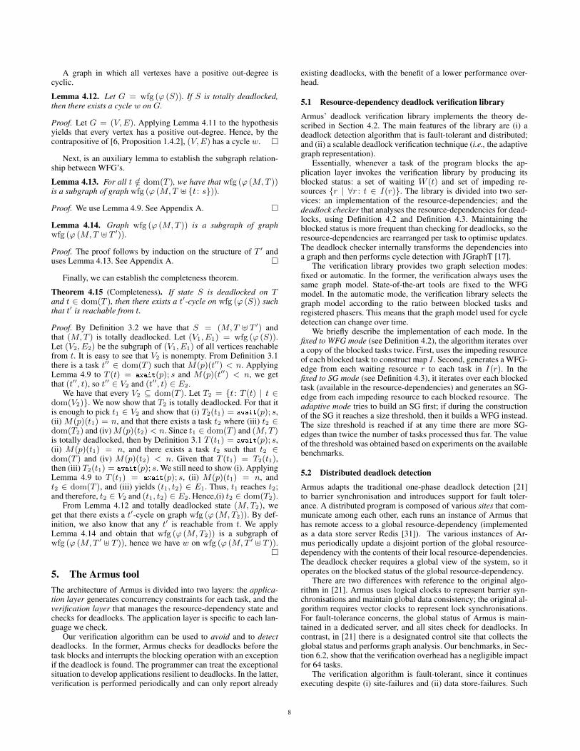
A graph in which all vertexes have a positive out-degree iscyclic.
Lemma 4.12. Let G = wfg (ϕ (S)). If S is totally deadlocked,then there exists a cycle w on G.
Proof. Let G = (V,E). Applying Lemma 4.11 to the hypothesisyields that every vertex has a positive out-degree. Hence, by thecontrapositive of [6, Proposition 1.4.2], (V,E) has a cycle w.
Next, is an auxiliary lemma to establish the subgraph relation-ship between WFG’s.
Lemma 4.13. For all t /∈ dom(T ), we have that wfg (ϕ (M,T ))is a subgraph of graph wfg (ϕ (M,T ] {t : s})).
Proof. We use Lemma 4.9. See Appendix A.
Lemma 4.14. Graph wfg (ϕ (M,T )) is a subgraph of graphwfg (ϕ (M,T ] T ′)).
Proof. The proof follows by induction on the structure of T ′ anduses Lemma 4.13. See Appendix A.
Finally, we can establish the completeness theorem.
Theorem 4.15 (Completeness). If state S is deadlocked on Tand t ∈ dom(T ), then there exists a t′-cycle on wfg (ϕ (S)) suchthat t′ is reachable from t.
Proof. By Definition 3.2 we have that S = (M,T ] T ′) andthat (M,T ) is totally deadlocked. Let (V1, E1) = wfg (ϕ (S)).Let (V2, E2) be the subgraph of (V1, E1) of all vertices reachablefrom t. It is easy to see that V2 is nonempty. From Definition 3.1there is a task t′′ ∈ dom(T ) such that M(p)(t′′) < n. ApplyingLemma 4.9 to T (t) = await(p); s and M(p)(t′′) < n, we getthat (t′′, t), so t′′ ∈ V2 and (t′′, t) ∈ E2.
We have that every V2 ⊆ dom(T ). Let T2 = {t : T (t) | t ∈dom(V2)}. We now show that T2 is totally deadlocked. For that itis enough to pick t1 ∈ V2 and show that (i) T2(t1) = await(p); s,(ii) M(p)(t1) = n, and that there exists a task t2 where (iii) t2 ∈dom(T2) and (iv)M(p)(t2) < n. Since t1 ∈ dom(T ) and (M,T )is totally deadlocked, then by Definition 3.1 T (t1) = await(p); s,(ii) M(p)(t1) = n, and there exists a task t2 such that t2 ∈dom(T ) and (iv) M(p)(t2) < n. Given that T (t1) = T2(t1),then (iii) T2(t1) = await(p); s. We still need to show (i). ApplyingLemma 4.9 to T (t1) = await(p); s, (ii) M(p)(t1) = n, andt2 ∈ dom(T ), and (iii) yields (t1, t2) ∈ E1. Thus, t1 reaches t2;and therefore, t2 ∈ V2 and (t1, t2) ∈ E2. Hence,(i) t2 ∈ dom(T2).
From Lemma 4.12 and totally deadlocked state (M,T2), weget that there exists a t′-cycle on graph wfg (ϕ (M,T2)). By def-inition, we also know that any t′ is reachable from t. We applyLemma 4.14 and obtain that wfg (ϕ (M,T2)) is a subgraph ofwfg (ϕ (M,T ′ ] T )), hence we have w on wfg (ϕ (M,T ′ ] T )).
5. The Armus toolThe architecture of Armus is divided into two layers: the applica-tion layer generates concurrency constraints for each task, and theverification layer that manages the resource-dependency state andchecks for deadlocks. The application layer is specific to each lan-guage we check.
Our verification algorithm can be used to avoid and to detectdeadlocks. In the former, Armus checks for deadlocks before thetask blocks and interrupts the blocking operation with an exceptionif the deadlock is found. The programmer can treat the exceptionalsituation to develop applications resilient to deadlocks. In the latter,verification is performed periodically and can only report already
existing deadlocks, with the benefit of a lower performance over-head.
5.1 Resource-dependency deadlock verification library
Armus’ deadlock verification library implements the theory de-scribed in Section 4.2. The main features of the library are (i) adeadlock detection algorithm that is fault-tolerant and distributed;and (ii) a scalable deadlock verification technique (i.e., the adaptivegraph representation).
Essentially, whenever a task of the program blocks the ap-plication layer invokes the verification library by producing itsblocked status: a set of waiting W (t) and set of impeding re-sources {r | ∀r : t ∈ I(r)}. The library is divided into two ser-vices: an implementation of the resource-dependencies; and thedeadlock checker that analyses the resource-dependencies for dead-locks, using Definition 4.2 and Definition 4.3. Maintaining theblocked status is more frequent than checking for deadlocks, so theresource-dependencies are rearranged per task to optimise updates.The deadlock checker internally transforms the dependencies intoa graph and then performs cycle detection with JGraphT [17].
The verification library provides two graph selection modes:fixed or automatic. In the former, the verification always uses thesame graph model. State-of-the-art tools are fixed to the WFGmodel. In the automatic mode, the verification library selects thegraph model according to the ratio between blocked tasks andregistered phasers. This means that the graph model used for cycledetection can change over time.
We briefly describe the implementation of each mode. In thefixed to WFG mode (see Definition 4.2), the algorithm iterates overa copy of the blocked tasks twice. First, uses the impeding resourceof each blocked task to construct map I . Second, generates a WFG-edge from each waiting resource r to each task in I(r). In thefixed to SG mode (see Definition 4.3), it iterates over each blockedtask (available in the resource-dependencies) and generates an SG-edge from each impeding resource to each blocked resource. Theadaptive mode tries to build an SG first; if during the constructionof the SG it reaches a size threshold, then it builds a WFG instead.The size threshold is reached if at any time there are more SG-edges than twice the number of tasks processed thus far. The valueof the threshold was obtained based on experiments on the availablebenchmarks.
5.2 Distributed deadlock detection
Armus adapts the traditional one-phase deadlock detection [21]to barrier synchronisation and introduces support for fault toler-ance. A distributed program is composed of various sites that com-municate among each other, each runs an instance of Armus thathas remote access to a global resource-dependency (implementedas a data store server Redis [31]). The various instances of Ar-mus periodically update a disjoint portion of the global resource-dependency with the contents of their local resource-dependencies.The deadlock checker requires a global view of the system, so itoperates on the blocked status of the global resource-dependency.
There are two differences with reference to the original algo-rithm in [21]. Armus uses logical clocks to represent barrier syn-chronisations and maintain global data consistency; the original al-gorithm requires vector clocks to represent lock synchronisations.For fault-tolerance concerns, the global status of Armus is main-tained in a dedicated server, and all sites check for deadlocks. Incontrast, in [21] there is a designated control site that collects theglobal status and performs graph analysis. Our benchmarks, in Sec-tion 6.2, show that the verification overhead has a negligible impactfor 64 tasks.
The verification algorithm is fault-tolerant, since it continuesexecuting despite (i) site-failures and (ii) data store-failures. Such
8

feature is of special interest for checking fault-tolerant applications,like Resilient X10 [9]. The algorithm resists (i) because the dead-lock checker executes at each site and does not depend on the coop-eration of other sites to function. The algorithm resists (ii) becauseRedis itself is fault-tolerant.
5.3 Verifying barrier deadlocks in X10 and in Java
We present two verification applications to check for barrier dead-locks: JArmus for Java programs and Armus-X10 for X10 pro-grams. These tools work by “weaving” the verification into pro-grams. The input is a compiled program to be verified (Java byte-code); the output is a verified program (Java bytecode) that includesdynamic checks for deadlock verification. JArmus and Armus-X10layers implement the resource-dependency construction from Sec-tion 4.1.
JArmus and Armus-X10 share the same usage and design. Theimplementation of each of these verification tools is divided intotwo components: the resource mapper and the task observer. Theresource mapper converts synchronisation events to resources. Thetask observer intercepts blocking calls to inform Armus that thecurrent task is blocked with a set of resource edges.
Armus-X10 Armus-X10 can verify any program written in X10that uses: clocks, finishes, and the SPMDBarrier; the tool can ver-ify distributed applications. Unlike in Java, automatic instrumenta-tion is possible. The X10 runtime provides information about theregistered clocks and registered finishes of a given task, which isrequired to construct the concurrency dependencies of each task.X10 can be compiled to Java bytecode, called Managed X10, andto machine code, called Native X10. Currently, our application onlysupports Managed X10.
JArmus JArmus supports CountDownLatch, CyclicBarrier,Phaser, and ReentrantLock class operations of the standard JavaAPI. Unlike in X10 and HJ, the relationship between the partici-pants of barrier synchronisation and tasks in Java is left implicit.For example, when using a CyclicBarrier the programmer de-clares the number of participants and then shares the object withthose many tasks, but it is not specified which tasks participate inthe synchronisation. This missing information, which the Armusanalysis requires, is also necessary to extend the Java implementa-tion of phasers to support the full range of features in the originalphaser semantics [34]. For instance, only by knowing exactly whichtasks are participants can phasers allow some tasks to advance with-out waiting. Since JArmus has no way of reconstructing this infor-mation for the CountDownLatch, CyclicBarrier, and Phaser
classes, then the programmer must annotate its code to supply thebarriers each task is registered with. Each task, upon starting up,must invoke JArmus.register(b) per barrier b it uses (similarly tothe X10 clocked). Instances of the class ReentrantLock do notrequire annotations.
6. EvaluationThe aim of the evaluation process is to 1) ascertain whether the per-formance impact of Armus scales with the increase in the numberof tasks, 2) evaluate the performance overhead of distributed dead-lock detection, and 3) compare execution impact the SG with theWFG and with adaptive approach.
The hardware used to run the benchmarks has four AMDOpteron 6376 processors, each with 16 cores, making a total of64 cores. There are 64GB of available RAM. The operating sys-tem used is Ubuntu 13.10. For the languages, we used Java build1.8.0_05-b13, and X10 version 2.4.3. For compiling and runningwe used the defaults flags with no additional parameters, except inthe case of the NPB suite that is compiled with -O.
Table 1: Relative execution overhead in detection mode.
Threads 2 4 8 16 32 64
BT 3% -4% 0% -5% 0% 7%CG 7% 0% 7% 15% 12% 9%FT 1% 0% -1% -7% 0% 0%MG -5% 0% 0% 0% 11% 13%RT -4% 0% 0% 0% 0% 8%SP -1% 4% 4% 2% 0%
Table 2: Relative execution overhead in avoidance mode.
Threads 2 4 8 16 32 64
BT 5% 0% 0% 0% 11% 8%CG 0% 9% 20% 34% 46% 50%FT 1% 4% 0% 0% 7% 25%MG 8% 7% 21% 27% 27% 30%RT -5% 0% 0% 0% 5% 16%SP 2% 9% 8% 22% 28%
We follow the start-up performance methodology detailed in[11]. We take 31 samples of the execution time of each benchmarkand discard the first sample. Next, we compute the mean of the30 samples with a confidence interval of 95%, using the standardnormal z-statistic.
6.1 Impact of non-distributed verification
The two goals of this evaluation are: to measure the impact of ver-ification on standard Java benchmarks, and ii) to measure whetherthe verification scales with the increase of the number of tasks.We run the verification algorithm against a set of standard paral-lel benchmarks available for Java. JArmus is run in the detectionmode (every 100 milliseconds) and in the avoidance mode, bothuse the adaptive graph model. Note that the Java applications wechecked are not distributed.
We select benchmarks from the NASA Parallel Benchmark(NPB) suite [10] and the Java Grande Forum (JGF) [39] bench-mark suite. The NPB ranges from kernels to pseudo-applications,taken primarily from representative Computational Fluid Dynamics(CFD) parallel applications. The JGF is divided into three groupsof applications: micro-benchmarks, computational kernels, andpseudo-applications. All benchmarks proceed iteratively, and usea fixed number of cyclic barriers to synchronise stepwise. Further-more, all benchmarks check the validity of the produced output.
For the sake of reproducibility we list the parameters of thebenchmarks run as specified in [10, 39]: BT uses size A, CG usessize C, the Java version of FT uses size B, MG uses size C, RT usesB, and SP uses size W. The input set chosen for benchmark SP onlyallows it to scale up to 31 tasks. For simplicity, in the evaluation weconsider that this benchmark scales up to 32 tasks.
Figure 6 summarises the comparative study of the executiontime for each benchmark. Tables 1 and 2 list the relative runtimeoverhead in detection and in avoidance. The results for the NPBand JGF benchmark suites are depicted in Figures 6a to 6f. In de-tection mode, since there is a dedicated task to perform verification,we observe that the overhead does not increase linearly as we addmore tasks. The relative runtime overhead sits below 15% and inmost cases is negligible. In avoidance mode, each task checks thegraph whenever it blocks, so as we add more tasks, the executionoverhead increases. Still, in the worst case, benchmark CG, the over-head is 50%, which is acceptable for application testing purposes.
9

..
2
.
4
.
8
.
16
.
32
.
64
.
Task count
.
0
.
100
.
200
.
300
.
400
.
500
.
600
.
700
.
800
.
900
.
Exec
utio
ntim
e(s
)
(a) Benchmark BT
..
2
.
4
.
8
.
16
.
32
.
64
.
Task count
.
0
.
20
.
40
.
60
.
80
.
100
.
120
.
140
.
160
.
180
.
Exec
utio
ntim
e(s
)
(b) Benchmark CG
..
2
.
4
.
8
.
16
.
32
.
64
.
Task count
.
0
.
20
.
40
.
60
.
80
.
100
.
Exec
utio
ntim
e(s
)
(c) Benchmark FT
..
2
.
4
.
8
.
16
.
32
.
64
.
Task count
.
0
.
20
.
40
.
60
.
80
.
100
.
120
.
140
.
Exec
utio
ntim
e(s
)
(d) Benchmark MG
..
2
.
4
.
8
.
16
.
32
.
Task count
.
0
.
50
.
100
.
150
.
200
.
250
.
300
.
Exec
utio
ntim
e(s
)
(e) Benchmark SP
..
2
.
4
.
8
.
16
.
32
.
64
.
Task count
.
0
.
2
.
4
.
6
.
8
.
10
.
12
.
14
.
Exec
utio
ntim
e(s
)
(f) Benchmark RT
Figure 6: Comparative execution time for non-distributed benchmarks (lower means faster).
6.2 Impact of distributed verificationThe goal of the evaluation is to measure the runtime overheadof deadlock detection in available X10 distributed applications.Armus-X10 is configured with the distributed deadlock detectionmode, running the verification algorithm every 200 milliseconds.The chosen benchmarks are available via the X10 source coderepository [45]. Deadlock avoidance is unavailable in the dis-tributed setting.
Benchmarks FT and STREAM come from the HPC Challengebenchmark [26], SSAC2 is an HPCS Graph Analysis Bench-mark [5], JACOBI and KMEANS are available from the X10’s web-site. For reproducibility purposes the non-default parameters weselect are: FT magnitude 11; KMEANS 25k points, 3k clusters tofind, and 5 iterations; JACOBI matrix of size 40, maximum itera-tions are 40; SSCA2 215 vertices, a with a probability of 7%, andno permutations; STREAM with size of 524k.
Figure 7 depicts the execution time of each benchmark with andwithout verification. There is no statistical evidence of an executionoverhead with running deadlock detection mode.
6.3 Impact of the graph model choiceThe goal of this evaluation is to measure the impact of the graphmodel in the verification procedure. To this end we analyse theworst case behaviour: programs that generate graphs with thou-sands of edges. In particular, we evaluate our adaptive model se-lection against the usual fixed model selection (WFG and SG).
We select a suite of programs that spawn tasks and create bar-riers as needed, depending on the size of the program, unlike theclassical parallel applications we benchmark in Sections 6.1 and 6.2where the number of tasks should correspond to the number ofavailable processing units (cores). The suite of programs exercisesdifferent worst case scenarios for the verification algorithm: manytasks versus many barriers.
The chosen benchmarks are educative programs taken from thecourse on Principles and Practice of Parallel Programming, taughtby Martha A. Kim and Vijay A. Saraswat, Fall 2013 [46]. BFS per-forms a parallel breadth-first search on a randomly generated graph.There is a task per node being visited and a barrier per depth-levelof the graph. FI computes a Fibonacci number iteratively with a
shared array of clocked variables (each pairs a barrier with a num-ber). Each element of the array holds the outcome of a Fibonaccinumber. When the program starts it launches n tasks. The i-th taskstores its Fibonacci number in the i-th clocked variable and syn-chronises with task i + 1 and task i + 2 that read the producedvalue. FR computes a Fibonacci number recursively. Recursive callsare executed in parallel and a clocked variable synchronises thecaller with the callee. SE implements the Sieve of Eratosthenes us-ing clocked variables. There is a task per prime number and oneclocked variable per task. PS computes the prefix sum—or cumu-lative sum—for a given number of tasks. Given an input array withas many elements as there are tasks, the outcome of task i is thepartial sum of the array up to the i-th element. All tasks proceedstepwise and are synchronised by a global barrier.
Figures 8 and 9 depict the execution time of each benchmarkverified by Armus-X10 in avoidance and detection modes (respec-tively) where we vary the selection method of the graph model.Table 3 lists the average number of edges used in verification andthe relative execution time overhead of each benchmark.
We can classify the benchmarks in three groups according to theratio between the number of tasks and the number of resources: i)similar count of tasks and resources, benchmark SE; ii) much moreresources than tasks, benchmarks FI and FT; and iii) much moretasks than resources, benchmarks BFS and PS. When i) there are asmany resources as there are tasks, then all graph models performequally well. When ii) there are more resources than tasks, and iii)vice-versa, the choice of the graph model is of major importancefor a verification with low impact on the execution time.
Even in the worst case behaviour for analysis the largest ver-ification overhead with deadlock detection is 25%; for deadlockavoidance the largest is 117%. For both cases we consider adap-tive graph selection. Overall, the approach of the adaptive graphmodel outperforms the fixed graph model approach. The adaptiveapproach can save up to 9% of execution overhead in deadlock de-tection versus a fixed model. The graph model choice severely am-plifies the verification overhead in deadlock avoidance. The casein point is benchmark PS, where the verification overhead rangesfrom 600% (fixed) down to 82% (adaptive).
10

..
FT
.
KMEANS
.
JACOBI
.
SSCA2
.
STREAM
.
0
.
100
.
200
.
300
.
400
.
500
.
Exec
utio
ntim
e(s
)
.
Unchecked
.
Checked
Figure 7: Comparative execution timefor distributed deadlock detection (lowermeans faster).
..
SE
.
FI
.
FR
.
BFS
.
PS
.
0
.
10
.
20
.
30
.
40
.
50
.
60
.
70
.
80
.
90
.
Tim
e(s
)
.
Unchecked
.
Auto
.
SG
.
WFG
Figure 8: Comparative execution timefor different graph model choices (lowermeans faster), using deadlock avoidance.
..
SE
.
FI
.
FR
.
BFS
.
PS
.
0
.
5
.
10
.
15
.
20
.
25
.
Tim
e(s
)
.
Unchecked
.
Auto
.
SG
.
WFG
Figure 9: Comparative execution timefor different graph model choices (lowermeans faster), using deadlock detection.
Table 3: Edge count and verification overhead per benchmark pergraph mode.
SE FI FR BFS PS
Auto
Edges 23 1074 140 5 7Avoidance 75% 94% 117% 45% 82%Detection 25% 24% 25% 9% 18%
SG
Edges 51 2137 1643 7 6Avoidance 75% 112% 300% 45% 82%Detection 25% 24% 25% 9% 18%
WFG
Edges 23 1281 94 579 781Avoidance 75% 94% 117% 200% 600%Detection 25% 29% 25% 18% 27%
7. Related workThis section lists related work focusing on deadlock verification inparallel programming languages.
Deadlock prevention The literature around source code analy-sis to prevent barrier related deadlocks is vast. The fork/join pro-gramming model is easily restricted syntactically to prevent dead-locks from happening. Lee and Palsberg present a calculus for afork/join programming model [24], suited for inter-procedural anal-ysis through type inference, and establish a deadlock freedom prop-erty. The work also includes a type system that is used to identifymay-happen-parallelism, further explored in [1]. Finally, relatedwork on “barrier matching” tackles the problem of barrier dead-locks in a setting where there is only global barrier synchronisa-tion [19, 47].
Cogumbreiro et al. [8] propose a static typing system to ensurethe correctness of phased activities for a fragment of X10 thatdisallows awaiting on a particular clock. Therefore, programs thatinvolve more than one clock and that perform single waits cannotbe expressed, nor verified (cf. the X10 and Java programs wepresent in Section 2).
Other works on the formalisation of barrier semantics are notconcerned with deadlock-freedom. Saraswat and Jagadeesan [33]formalise the concurrency primitives of X10. Le et al. devise averification for the correct use of a cyclic barrier in a fork/joinprogramming language [23]. Vasudevan et al. [43] perform staticanalysis to improve performance of synchronisation mechanisms.
The tool X10X [12] is a model checker for X10. Model check-ers perform source code analysis and can be used to discover po-tential deadlocks. This class of tools is affected by the state explo-sion problem: the analysis grows exponentially with the possibleinterleaves of the program. Thus, X10X may not be able to verify
complex programs. In general, prevention is too limiting to be ap-plied to the whole system, so language designers use this strategyto eliminate just a class of deadlocks.
Deadlock avoidance To our best knowledge, techniques thatavoid deadlocks in the context of barrier synchronisation only han-dle a few situations of barrier deadlocks, unlike our proposal thatis complete (with reference to Theorem 4.15). For instance, in X10and HJ, tasks deregister from all barriers upon termination; thismitigates deadlocks that arise from missing participants. HJ avoidsdeadlocks that originate from the interaction between phasers andfinish blocks by limiting the use of phasers to the scope of finishblocks.
Deadlock detection UPC-CHECK [32] deals with deadlock de-tection, but in a simpler setting where barriers are global; in con-trast, our work can handle group synchronisation. Literature con-cerning MPI deadlock detection takes a top-down approach: thegeneral idea is given, but mapping it to the actual MPI semantics isleft out. DAMPI [44] reports a program as deadlocked after a periodof inactivity, so it may indicate false positives, i.e., it can misiden-tify a slow program as a deadlock. Umpire [13] and MUST [14](a successor of Umpire) use a graph-based deadlock detection al-gorithm that subsumes deadlock detection to cycle detection, butomit a formal description on how the graph is actually generatedfrom the language, cf. Theorems 4.10 and 4.15. We summarise thedistributed detection technique of MUST. First, all sites collaborateto generate a single stream of events to a central site. The difficultylays in ordering and aggregating the events generated by the vari-ous tasks. Then, the central site processes the stream of events toperform the collective checking, where, among other things, it iden-tifies any completed barrier synchronisations. Finally, since MUSTmaintains a distributed wait state, then the site performing the col-lective checking must broadcast the status of terminated synchro-nisations back to the various sites of the application. The wait stateis required to delay the graph analysis as much as possible. In ourapproach, tasks only requires local information to maintain dataconsistency, which means that, in a distributed setting, Armus doesnot require the last synchronisation step that MUST performs. Fur-thermore, unlike MUST, Armus is capable of verifying split-phasesynchronisation, known in MPI as non-blocking collective opera-tions.
8. ConclusionWe put forward Armus, a dynamic verification tool for barrier dead-locks that features distributed deadlock detection and a scalablegraph analysis technique (based on automatic graph model selec-tion). The target of verification is the core language PL, introducedto represent programs with various barrier synchronisation patterns.
11

The graph-based deadlock verification of Armus is formalised andshown to be sound and complete against PL. We establish an equiv-alence theorem between utilising the graph models WFG and SGfor deadlock detection; this result enables us to use the standardWFG to prove our results, and choose automatically between theWFG and the SG during verification. Our adaptive model selectiondramatically increases the performance against the fixed model se-lection. The runtime overhead of the deadlock detection is low forup to 64 tasks, in most cases negligible. We present two applica-tions: Armus-X10 monitors any unchanged X10 program for dead-locks; JArmus is a library to verify Java programs. To the best ofour knowledge, our work is the first dynamic verification tool thatcan correctly detect Java and X10 barrier deadlocks.
For future work, we intend to verify HJ programs, as it will ex-ercise the expressiveness of Armus. This language features abstrac-tions with complex synchronisation patterns, such as the boundedproducer-consumer. Another direction is the verification of MPIprograms that introduce complex patterns of point-to-point syn-chronisation and enable a direct comparison with state-of-the-artin barrier deadlock detection.
Acknowledgements We thank Olivier Tardieu and PPoPP re-viewers for their comments and suggestions. The work is par-tially supported by EPSRC KTS with Cognizant, EP/K034413/1,EP/K011715/1 and EP/L00058X/1, EU project FP7-612985 Up-Scale and ICT COST Action 1201 BETTY.
References[1] S. Agarwal, R. Barik, V. Sarkar, and R. K. Shyamasundar. May-
happen-in-parallel analysis of X10 programs. In PPoPP’10, pages183–193. ACM, 2007.
[2] S. Agarwal, S. Joshi, and R. K. Shyamasundar. Distributed general-ized dynamic barrier synchronization. In ICDCN’11, pages 143–154.Springer, 2011.
[3] Armus homepage. bitbucket.org/cogumbreiro/armus/wiki/PPoPP15.
[4] D. Atkins, A. Potanin, and L. Groves. The design and implementationof clocked variables in X10. In ACSC’13, pages 87–95. AustralianComputer Society, 2013.
[5] D. A. Bader and K. Madduri. Design and implementation of the HPCSgraph analysis benchmark on symmetric multiprocessors. In HiPC’05,volume 3769 of LNCS, pages 465–476. Springer, 2005.
[6] J. Bang-Jensen and G. Z. Gutin. Digraphs: Theory, Algorithms andApplications. Springer, 2nd edition, 2009.
[7] V. Cavé, J. Zhao, J. Shirako, and V. Sarkar. Habanero-Java: the newadventures of old X10. In PPPJ’11, pages 51–61. ACM, 2011.
[8] T. Cogumbreiro, F. Martins, and V. T. Vasconcelos. Coordinatingphased activities while maintaining progress. In COORDINATION’13,volume 7890 of LNCS, pages 31–44. Springer, 2013.
[9] D. Cunningham, D. Grove, B. Herta, A. Iyengar, K. Kawachiya,H. Murata, V. Saraswat, M. Takeuchi, and O. Tardieu. Resilient X10:Efficient failure-aware programming. In PPoPP’14, pages 67–80.ACM, 2014.
[10] M. A. Frumkin, M. Schultz, H. Jin, and J. Yan. Performance andscalability of the NAS Parallel Benchmarks in Java. In IPDPS’03.IEEE, 2003.
[11] A. Georges, D. Buytaert, and L. Eeckhout. Statistically rigorous Javaperformance evaluation. In OOPSLA’07, pages 57–76. ACM, 2007.
[12] M. Gligoric, P. C. Mehlitz, and D. Marinov. X10X: Model checking anew programming language with an "old" model checker. In ICST’12,pages 11–20. IEEE, 2012.
[13] T. Hilbrich, B. R. de Supinski, M. Schulz, and M. S. Müller. A graphbased approach for MPI deadlock detection. In ICS’09, pages 296–305. ACM, 2009.
[14] T. Hilbrich, J. Protze, M. Schulz, B. R. de Supinski, and M. S. Müller.MPI runtime error detection with MUST: advances in deadlock detec-tion. In SC’12, pages 1–11. IEEE, 2012.
[15] R. C. Holt. Some deadlock properties of computer systems. ACMComputing Surveys, 4(3):179–196, Sept. 1972.
[16] Java 7 Phaser API. docs.oracle.com/javase/7/docs/api/java/util/concurrent/Phaser.html.
[17] JGraphT homepage. jgrapht.org.[18] E. G. C. Jr., M. J. Elphick, and A. Shoshani. System deadlocks. ACM
Computing Surveys, 3(2):67–78, 1971.[19] A. Kamil and K. Yelick. Enforcing textual alignment of collectives
using dynamic checks. In LCPC’09, volume 5898 of LNCS, pages368–382. Springer, 2009.
[20] E. Knapp. Deadlock detection in distributed databases. ACM Comput-ing Survey, 19(4):303–328, 1987.
[21] A. D. Kshemkalyani and M. Singhal. Correct two-phase and one-phase deadlock detection algorithms for distributed systems. InSPDP’90, pages 126–129, 1990.
[22] L. Lamport. Time, clocks, and the ordering of events in a distributedsystem. Communications of the ACM, 21(7):558–565, 1978.
[23] D.-K. Le, W.-N. Chin, and Y.-M. Teo. Verification of static anddynamic barrier synchronization using bounded permissions. InICFEM’13, volume 8144 of LNCS, pages 231–248. Springer, 2013.
[24] J. K. Lee and J. Palsberg. Featherweight X10: a core calculus forasync-finish parallelism. In PPoPP’10, pages 25–36. ACM, 2010.
[25] D. Leijen, W. Schulte, and S. Burckhardt. The design of a task parallellibrary. In OOPSLA’09, pages 227–242. ACM, 2009.
[26] P. R. Luszczek, D. H. Bailey, J. J. Dongarra, J. Kepner, R. F. Lucas,R. Rabenseifner, and D. Takahashi. The HPC Challenge (HPCC)benchmark suite. In SC’06. ACM, 2006.
[27] S. Marr, S. Verhaegen, B. D. Fraine, T. D’Hondt, and W. D. Meuter.Insertion tree phasers: Efficient and scalable barrier synchronizationfor fine-grained parallelism. In HPCC’10, pages 130–137. IEEE,2010.
[28] Message Passing Interface (MPI) homepage. mpi-forum.org.[29] M. T. O’Keefe and H. G. Dietz. Hardware barrier synchronization:
Dynamic barrier MIMD (DBM). In ICPP’90, pages 43–46. Pennsyl-vania State University, 1990.
[30] OpenMP homepage. openmp.org.[31] Redis homepage. redis.io.[32] I. Roy, G. R. Luecke, J. Coyle, and M. Kraeva. A scalable deadlock
detection algorithm for UPC collective operations. In PGAS’13, pages2–15. The University of Edinburgh, 2013.
[33] V. Saraswat and R. Jagadeesan. Concurrent clustered programming. InCONCUR’05, volume 3653 of LNCS, pages 353–367. Springer, 2005.
[34] J. Shirako, D. M. Peixotto, V. Sarkar, and W. N. Scherer. Phasers: aunified deadlock-free construct for collective and point-to-point syn-chronization. In ICS’08, pages 277–288. ACM, 2008.
[35] J. Shirako, D. M. Peixotto, V. Sarkar, and W. N. Scherer. Phaseraccumulators: A new reduction construct for dynamic parallelism. InIPDPS’09, pages 1–12. IEEE, 2009.
[36] J. Shirako, D. M. Peixotto, D.-D. Sbîrlea, and V. Sarkar. Phaser beams:Integrating stream parallelism with task parallelism. Presented at theX10’11, 2011.
[37] J. Shirako and V. Sarkar. Hierarchical phasers for scalable synchro-nization and reductions in dynamic parallelism. In IPDPS’10, pages1–12. IEEE, 2010.
[38] J. Shirako, K. Sharma, and V. Sarkar. Unifying barrier and point-to-point synchronization in OpenMP with Phasers. In IWOMP’11,volume 6665 of LNCS, pages 122–137. Springer, 2011.
[39] L. A. Smith, J. M. Bull, and J. Obdrzálek. A parallel Java Grandebenchmark suite. In SC’01. ACM, 2001.
[40] R. Tarjan. Depth-first search and linear graph algorithms. SIAMJournal on Computing, 1(2):146–160, 1972.
[41] F. Turbak. First-class synchronization barriers. In ICFP’96, pages157–168. ACM, 1996.
12

[42] UPC homepage. upc-lang.org.[43] N. Vasudevan, O. Tardieu, J. Dolby, and S. A. Edwards. Compile-
time analysis and specialization of clocks in concurrent programs. InCC’09, volume 5501 of LNCS, pages 48–62. Springer, 2009.
[44] A. Vo. Scalable Formal Dynamic Verification of MPI ProgramsThrough Distributed Causality Tracking. PhD thesis, University ofUtah, 2011. AAI3454168.
[45] X10 homepage. x10-lang.org.[46] Course materials of principles and practice of parallel programming.
www.cs.columbia.edu/~martha/courses/4130/au13/, 2013.[47] Y. Zhang, E. Duesterwald, and G. R. Gao. Concurrency analysis
for shared memory programs with textually unaligned barriers. InLCPC’08, volume 5234 of LNCS, pages 95–109. Springer, 2008.
A. Appendix: Proofs of Section 4.3Lemma 4.5 We have that t1t2 is a walk on wfg (D) if, and onlyif, there exists a resource r such that t1rt2 is a walk on grg (D).
Proof. ( =⇒ ) Let grg (D) = (V,E) and wfg (D) = (V ′, E′).Since t1t2 is a walk on wfg (D), then t1t2 ∈ E′. By Definition 4.2there exists a vertex r such that r ∈ W (t1) and t2 ∈ I(r). Thus,by Definition 4.4 (t1, r) ∈ E and (r, t2) ∈ E, and therefore t1rt2is a walk on grg (D).
( ⇐= ) Let grg (D) = (V,E). Since t1rt2 is a walkon grg (D), then (t1, r) ∈ E and (r, t2) ∈ E. From Defini-tion 4.4 r ∈ W (t1) and t2 ∈ I(r). Let wfg (D) = (V ′, E′).Thus, from Definition 4.2 t1t2 ∈ E′ and therefore t1t2 is a walkon wfg (D).
Lemma 4.7 If w = t1 · · · tn is has a positive length on wfg (D)and 1 < k < n, then there exists a walk w′ = r1 · · · rk on sg (D)such that for all i where 1 ≤ i ≤ k we have tiriti+1 is a walk ongrg (D).
Proof. • Case k = 2, where w = t1t2t3 · · · tn is a walkon wfg (D) and n ≥ 3. Applying Lemma 4.5 to t1t2 is awalk on wfg (D), yields that there exists a resource r1 suchthat t1r1t2 is a walk on grg (D). Similarly, from Lemma 4.5and t2t3 is a walk on wfg (D), we get that there exists a re-source r2 such that t2r2t3 is a walk on grg (D). Finally, wehave that r1t2r2 is a walk on grg (D), hence by Lemma 4.6,r1r2 is a walk on sg (D).• Case k = j + 1, where w = t1 · · · tjtj+1 · · · tn is a walk
on wfg (D) and n > j ≥ 2. By the induction hypothesis wehave that there exists a walk r1 · · · rj on sg (D) such that (i) forall i where 1 ≤ i ≤ j we have tiriti+1 is a walk on grg (D).From (i), we have that (ii) tjrjtj+1 is a walk on grg (D).By hypothesis, we also have that tj+1tj+2 is a walk on wfg (D),thus from Lemma 4.5, there exists a resource rj+1 such that(iii) tj+1rj+1tj+2 is a walk on grg (D).From (ii) tjrjtj+1 and (iii) tj+1rj+1tj+2 walks on grg (D), weget that rjtjrj+1 is a walk on grg (D). Applying Lemma 4.6to the latter, yields that rjrj+1 is a walk on sg (D). Thus,r1 · · · rjrj+1 is a walk on sg (D) and we are left with provingfor all i where 1 ≤ i ≤ j + 1 we have tiriti+1 is a walk ongrg (D). But, we already know that (i) for all iwhere 1 ≤ i ≤ jwe have tiriti+1 is a walk on grg (D), so we just need to provethat tj+1rj+1tj+2 is a walk on grg (D), which we have alreadyshown with (iii).
Lemma 4.9 Let ϕ (M,T ) = (I,W ), wfg (D) = (V,E),res (p, n) = r. We have that (t1, t2) ∈ E if, and only if,T (t1) = await(p); s, M(p)(t1) = n, and M(p)(t2) < n.
Proof. ( =⇒ ) We have that (t1, t2) ∈ E, thus by Definition 4.2there is a resource r such that r ∈ W (t1) and t2 ∈ I(r). FromDefinition 4.1 and r ∈ W (t1), we get that T (t1) = await(p); s,M(p)(t1) = n, and res (p, n) = r. From Definition 4.1 andt2 ∈ I(r), we obtain that M(p)(t2) < n.
(⇐= ) We have that T (t1) = await(p); s,M(p)(t1) = n, andM(p)(t2) < n. From Definition 4.1, T (t1) = await(p); s, andM(p)(t1) = n, yields a resource r such that res (p, n) = r andr ∈ W (t1). From Definition 4.1 and M(p)(t2) < n, we get thatt1 ∈ I(r). We apply Definition 4.2 to t1 ∈ I(r) and r ∈ W (t2)and get that (t1, t2) ∈ E.
Lemma 4.13 For all t /∈ dom(T ), we have that
wfg (ϕ (M,T ))
is a subgraph of graph wfg (ϕ (M,T ] {t : s})).
Proof. Let wfg (ϕ (M,T )) = (V,E) and
wfg (ϕ (M,T ] {t : s})) = (V ′, E′)
Graph (V,E) is a subgraph of (V ′, E′) if 1) V ⊆ V ′, 2) E ⊆ E′,3) ∀(t, t′) ∈ E =⇒ t ∈ V ∧ t′ ∈ V .
1. We have that V ⊆ V ′ holds, since V = V ′ = T .2. If (t1, t2) ∈ E, then (t1, t2) ∈ E′. By Lemma 4.9 and
(t1, t2) ∈ E, we have that T (t2) = await(p); s′, M(p)(t2) =n, and M(p)(t1) < n. We have that t /∈ dom(T ), thusT ] {t : s}(t2) = await(p); s′. From T ] {t : s}(t2) =await(p); s′, M(p)(t1) < n,
wfg (ϕ (M,T ] {t : s})) = (V ′, E′)
and Lemma 4.9, we get that (t1, t2) ∈ E′.3. We show that ∀(t, t′) ∈ E =⇒ t ∈ V ∧ t′ ∈ V . By
definition t ∈ T and t′ ∈ T .
Lemma 4.14 Graph wfg (ϕ (M,T )) is a subgraph of graphwfg (ϕ (M,T ] T ′)).
Proof. The proof follows by induction on the structure of T ′ anduses Lemma 4.13.
The proof follows by induction on the structure of T ′. Let
wfg (ϕ (M,T )) = (V,E)
andwfg (ϕ (M,T ] T ′)) = (V ′, E′)
We inspect T ′.
• Case T ′ is ∅. To show that (V,E) is subgraph of itself, we justneed to show that ∀(t, t′) ∈ E =⇒ t ∈ V ∧ t′ ∈ V , whichholds by Definition 4.2, since V = V ′ = T .• Case T ′ is T ′′ ] {t : s}. By the induction hypothesis, we have
that wfg (ϕ (M,T )) is a subgraph of wfg (ϕ (M,T ] T ′′)). ByLemma 4.13 this case holds.
13