Dynamic behavior and control requirements of an ...
87
3 445b 0263000 8 &%T 21
Transcript of Dynamic behavior and control requirements of an ...

3 445b 0263000 8
&%T 21


ORNE/TM-9821
Instrumentation and Controls Division
DYNAMIC BEHAVIOR AND CONTROL REQUIREMENTS OF A M ATMOSPHERIC FLUIDIZED-BED COAL COMBUSTION POWER PLANT:
A CONCEPTUAL STUDY
0. L . Smith
Date of 1ssue:June 1987
Prepared by the OAK RIDGE NATIONAL LABORATORY Oak Ridge, Tennessee 37831
operated by MARTIN MARIETTA ENERGY SYSTEMS, INC.
for the U.S. DEPARTMENT OF ENERGY
under Contract No. DE-AC05-840R21400
3 4456 0263000 8


TABLE OF CONTENTS
LIST OF FIGURES . . . . . . . . . . . . . . . . . . . . . . . . . . V
L I S T OF TABLES . . . . . . . . . . . . . . . . . . . . . . . . . . v i i i
ABSTRACT . . . . . . . . . . . . . . . . . . . . . . . . . . . . . i x
1 INTRODUCTION 1 . . . . . . . . . . . . . . . . . . . . . . . . . . 2 . MATHEMATICAL DEVELOPMENT . . . . . . . . . . . . . . . . . . . 7
2.1 WATER/STEAM C I R C U I T . . . . . . . . . . . . . . . . . . . 7 2.1.1 B o i l e r . . . . . . . . . . . . . . . . . . . . . . 7 2.1.2 Primary Supe rhea te r . . . . . . . . . . . . . . . . 18 2.1.3 Secondary ( Inbed) Supe rhea te r . . . . . . . . . . . 19 2.1.4 Steam Drum . . . . . . . . . . . . . . . . . . . . 20 2.1.5 At tempera tor . . . . . . . . . . . . . . . . . . . 21 2.1.6 Air-cooled Condenser . . . . . . . . . . . . . . . 22 2.1.7 Economizer . . . . . . . . . . . . . . . . . . . . 23
2.2 A I R AND GAS PATH . . . . . . . . . . . . . . . . . . . . . 23 2.2.1 A i r P r e h e a t e r . . . . . . . . . . . . . . . . . . . 23 2.2.2 Forced Draft Flow . . . . . . . . . . . . . . . . . 24 2.2.3 Bed . . . . . . . . . . . . . . . . . . . . . . . . 25 2.2.4 Convect ion Zone . . . . . . . . . . . . . . . . . . 31 2.2.5 Induced Dra f t Flow . . . . . . . . . . . . . . . . 32
2.3 SUMMARY OF STATE VARIABLE EQUATIONS . . . . . . . . . . . 33
3 . PARAMETERS . . . . . . . . . . . . . . . . . . . . . . . . . . 3‘1
4 . OPEN-LOOP ANALYSIS . . . . . . . . . . . . . . . . . . . . . . 35
4.1 INHERENT DYNAMICS . . . . . . . . . . . . . . . . . . . . 35 4.1.1 A i r I n l e t Damper S e t t i n g . . . . . . . . . . . . . 42
4.1.3 Primary Supe rhea te r T r a n s f e r Su r face . . . . . . . 44 4.1.2 E f f e c t i v e Evapora tor Heat T r a n s f e r Su r face . . . . 43
4 .1 .4 Secondary (Bed) Supe rhea te r T r a n s f e r S u r f a c e . . . 44
4.2 INFLUENCE OF FEEDWATER H E A T I N G ON D Y N A M I C S . . . . . . . . 45
5 . PLANT CONTROL . . . . . . . . . . . . . . . . . . . . . . . . . 47
5.1 CONTROLLER DESIGN . . . . . . . . . . . . . . . . . . . . 47 5.2 CONTROLLER T U N I N G . . . . . . . . . . . . . . . . . . . . 49 5.3 TIME DELAYS I N A FLUID-BED PLANT . . . . . . . . . . . . . 50 5.4 LOAD FOLLOWING . . . . . . . . . . . . . . . . . . . . . . 55
5.4.1 Abrupt Change . . . . . . . . . . . . . . . . . . . 55 5.4.2 Ramp Change . . . . . . . . . . . . . . . . . . . . 56
iii

ACKNOWLEDGMENT . . . . . . . . . . . . . . . . . . . . . . . . . . 71
REFERENCES . . . . . . . . . . . . . . . . . . . . . . . . . . . . 72
APPENDIX . . . . . . . . . . . . . . . . . . . . . . . . . . . . . 73
iv

LIST OF FIGURES
FIGURE PAGE
1 . Model of a f l u i d - b e d p i l o t p l a n t . . . . . . . . . . . . . . . 5
2a . SO. i n f l u e gas . . . . . . . . . . . . . . . . . . . . . . . 30
2b . T o t a l e l u t r i a t i o n as a f u n c t i o n of s u p e r f i c i a l . v e l o c i t y . . . . . . . . . . . . . . . . . . . . . . . . . . . 30
3a . Open-loop r e sponse t o 1 % r e d u c t i o n of c o a l feed . . . . . . . 39
3b . Power g e n e r a t i o n i n evapora to r . . . . . . . . . . . . . . . . 39
3c . Power g e n e r a t i o n i n p r imary (above-bed) s u p e r h e a t e r . . . . . . 39
3d . Power g e n e r a t i o n i n secondary ( in-bed) s u p e r h e a t e r . . . . . . 39
3e . Bed t empera tu re . . . . . . . . . . . . . . . . . . . . . . . 40
3f . T h r o t t l e steam tempera tu re . . . . . . . . . . . . . . . . . . 40
3g . D r u m p r e s s u r e ( 1 ) and t h r o t t l e steam p r e s s u r e (2 ) . . . . . . 40
4 . Contro l sys t em . . . . . . . . . . . . . . . . . . . . . . . . 48
5 . C o n t r o l l e d r e sponse of drum ( 1 ) and t h r o t t l e ( 2 ) p r e s s u r e s to 5% s t e p r e d u c t i o n i n l o a d . . . . . . . . . . . . 51
6 . Divergent p r e s s u r e r e sponse w i t h g a i n i n c r e a s e d twofold . . . . . . . . . . . . . . . . . . . . . . . . . . . 51
7 . C o n t r o l l e d r e sponse of drum (1 1 and t h r o t t l e ( 2 ) p r e s s u r e s t o 5% s t e p change ih l o a d w i t h reset i n coa l - f eed l o o p . . . . . . . . . . . . . . . . . . . . . . 51
8 . React ion cu rve a n a l y s i s of system time l a g s . . . . . . . . . 53
9 . Effect of adding d e r i v a t i v e a c t i o n t o coa l - f eed c o n t r o l . . . 56
10a . Effect on system variables of 5% s t e p r e d u c t i o n i n l o a d . . . . . . . . . . . . . . . . . . . . . . . . . . . 57
10b . SO. c a p t u r e . . . . . . . . . . . . . . . . . . . . . . . . . 57
10c . Limestone feed . . . . . . . . . . . . . . . . . . . . . . . . 57
10d . Steam p r e s s u r e . . . . . . . . . . . . . . . . . . . . . . . . 57
10e . Coal feed . . . . . . . . . . . . . . . . . . . . . . . . . . 58
V

1 l a . Effect on system v a r i a b l e s of 25% runback of load a t ra te of 0.75%/min, w i t h bed slumping a f te r runback . . . . . . 60
I l b . Main steam flow . . . . . . . . . . . . . . . . . . . . . . . 60
l l c . Power g e n e r a t i o n . . . . . . . . . . . . . . . . . . . . . . . 60
l l d . Coal f e e d . . . . . . . . . . . . . . . . . . . . . . . . . . 60
I l e . S u p e r f i c i a l v e l o c i t y . . . . . . . . . . . . . . . . . . . . . 61
l l f . Steam p r e s s u r e . . . . . . . . . . . . . . . . . . . . . . . . 61
l l g . Temperature . . . . . . . . . . . . . . . . . . . . . . . . . 61
I l h . SO. c a p t u r e . . . . . . . . . . . . . . . . . . . . . . . . . 61
l l i . Limestone feed . . . . . . . . . . . . . . . . . . . . . . . . 62
l l j . Contro l v a l v e s e t t i n g s . . . . . . . . . . . . . . . . . . . . 62
I l k . F r a c t i o n of bed f l u i d i z e d and heat t r a n s f e r s u r f a c e a c t i v e . . . . . . . . . . . . . . . . . . . . . . . . . . . . 62
12a . Effect on s y s t e m v a r i a b l e s of 25% runback of l o a d a t 0.75$/min, w i t h v a r i a b l e bed h e i g h t . . . . . . . . . . . . . 64
12b . Main steam f low . . . . . . . . . . . . . . . . . . . . . . . 64
12c . Power g e n e r a t i o n . . . . . . . . . . . . . . . . . . . . . . . 64
1 2 d . Coal feed . . . . . . . . . . . . . . . . . . . . . . . . . . 64
12e . S u p e r f i c i a l v e l o c i t y . . . . . . . . . . . . . . . . . . . . . 65
12f . Steam p r e s s u r e . . . . . . . . . . . . . . . . . . . . . . . . 65
12g . Temperature . . . . . . . . . . . . . . . . . . . . . . . . . 65
12h . SO. c a p t u r e . . . . . . . . . . . . . . . . . . . . . . . . . 65
121. Limestone feed . . . . . . . . . . . . . . . . . . . . . . . . 66
1 2 j . Contro l v a l v e s e t t i n g s . . . . . . . . . . . . . . . . . . . . 66
1 2 k . F r a c t i o n of bed f l u i d i z e d and heat t r a n s f e r s u r f a c e a c t i v e . . . . . . . . . . . . . . . . . . . . . . . . . . . . 66
13a . Maximum load-fo l lowing c a p a b i l i t y (5%/min) u s i n g v a r i a b l e bed h e i g h t s . . . . . . . . . . . . . . . . . . . . . 68
vi

1313 . 13c . 136 . 13e . 13f . 13g-
13h . 13i . 13j
1 3 k .
Main steam f low . . . . . . . . . Power g e n e r a t i o n . . . . . . . . . Coal f e e d . . . . . . . . . . . . S u p e r f i c i a l v e l o c i t y . . . . . . . Steam p r e s s u r e . . . . . . . . . .
. .
......................
. . . . . . . . . . . . . . . . . . . . .
...................... Cont ro l va lve s e t t i n g s . . . . . . F r a c t i o n of bed f l u i d i z e d and heat a c t i v e . . . . . . . . . . . . . .
. . . . . . . . . . . . .
. . . . . . . . .
. . . . . . . . .
. . . . . . . . . . .
. . . . . . . . . . . . .
. . . . . . . . .
. . . . . . . . . . . . .
. . . . . . . . .
. . . . . . . . . t r a n s f e r s u r f ace . . . . . . . . .
. . . . . 68
. . . . . 68 . . . . .
. . . . . 68
. . . . . 69
. . . . . 69
. . . . . 69
. . .
. . . . . 69 . . .
. . . . . 70
. . . . . 70
. . . . . 70
vi i

L I S T OF TABLES
TABLE PAGE
1 . Symbols and v a l u e s . . . . . . . . . . . . . . . . . . . . . . 8
2 . Nominal v a l u e s o f parameters and v a r i a b l e s . . . . . . . . . . 36
3 . S e n s i t i v i t y of AFRC s ta te v a r i a b l e s t o changes i n selected system parameters . . . . . . . . . . . . . . . . . . 37
4 . Some e f f ec t s of adding feedwater h e a t i n g . . . . . . . . . . . 46
5 . C o n t r o l l e r s e t t i n g s . . . . . . . . . . . . . . . . . . . . . 49
6 . P r i n c i p a l system h e a t c a p a c i t i e s expres sed i n f u l l power minutes of stored heat . . . . . . . . . . . . . . . . . . . . 52
v i i i

ABSTRACT
A f i r s t - p r i n c i p l e s model of a nominal 20-Mn! a tmospher ic -pressure
f l u i d i z e d - b e d c o a l combustion (AFBC) power p l a n t was developed t o
provide i n s i g h t i n t o fundamental dynamic behavior of f l u i d i z e d - b e d
systems. A i r preheater, steam drum, e v a p o r a t o r , primary and secondary
s u p e r h e a t e r , induced and f o r c e d d ra f t f a n s , economizer, a t t e m p e r a t o r ,
bed, coal and l imes tone supply systems, and air-cooled condenser were
e x p l i c i t l y r e p r e s e n t e d . The a i r - g a s p a t h was included from i n t a k e t o
stack e x h a u s t , and the e n t i r e steam loop was treated except for
dynamical ly minor par ts such as the d e m i n e r a l i z a t i o n s y s t e m . The
c o n t r o l system inc luded major l o o p s f o r f i r i n g rate, steam p r e s s u r e and
tempera ture , forced and induced d ra f t a i r f low, SO, emiss ion , drum water
l e v e l , e v a p o r a t o r r e c i r c u l a t i o n , and bed l e v e l .
The model was used t o i n v e s t i g a t e system s e n s i t i v i t y t o d e s i g n
f e a t u r e s such as the d i s t r i b u t i o n of heat t r a n s f e r s u r f a c e among the bed
b o i l e r and s u p e r h e a t e r and the out-of-bed s u p e r h e a t e r . Also c a l c u l a t e d
were t h e s e n s i t i v i t i e s of t e m p e r a t u r e s , p r e s s u r e s , and flow rates t o
changes i n t h r o t t l e , attemperator, and feedwater v a l v e s e t t i n g s and
f o r c e d and induced d r a f t damper s e t t i n g s .
The large bed mass, account ing f o r -40% of the a c t i v e heat
c a p a c i t y , may vary under load change and could impact c o n t r o l l e r tun ing .
Model a n a l y s i s i n d i c a t e d , however, that f o r t he d e s i g n s t u d i e d , t he
change I n bed mass does n o t appear t o s i g n i f i c a n t l y a f f ec t c o n t r o l l e r
t u n i n g even i f t h e bed mass v a r i e s a p p r e c i a b l y under load- fo l lowing
c o n d i t i o n s .
S e v e r a l bed d e s i g n s are be ing cons idered for AFBC p l a n t s , some w i t h
p a r t i t i o n s between bed s e c t i o n s and some w i t h o u t , and these d i f f e r e n c e s
may s i g n i f i c a n t l y a f fec t the load- fo l lowing c a p a b i l i t y o f t he p l a n t .
One d e s i g n ca l l s f o r complete shutdown (s lumping) of i n d i v i d u a l s e c t i o n s
o f the bed a s load decreases. Another d e s i g n i n v o l v e s lowering the bed
he ight uniformly across the bed t o expose and d e a c t i v a t e submerged heat
t r a n s f e r t u b e s w i t h o u t s h u t t i n g down bed s e c t i o n s . The model was used
for comparat ive s t u d i e s of the maximum ra te of load change t h a t a p l a n t
i X

ccnuld fo l low w i t h the tido des igns . The second method showed
s i g n i f i c a n t l y b e t t e r c o n t r o l characteristics. The r e s u l t s i n d i c a t e d
t ha t t h e slumping mode of o p e r a t i o n can cause d i s t o r t i o n of t h e heat
s o u r c e / s i n k d i s t r i b u t i o n i n t h e bed such that t h e load- fo l lowing
c a p a b i l i t y ( r a t e of load change) of t he p l a n t may be reduced by as much
as a f a c t o r of 5 compared wi th t h e mode i n which t u b e s u r f a c e is
exposed.
X

1 a INTRODUCTION
A fluidized-bed power plant differs from a conventional pulverized
coal plant in ways that may result in significant differences in the
basic dynamics of the plant and control system. Early emphasis on these
differences may aid in matching the control package to the plant's
inherent behavior and reduce the likelihood of having to retrofit the
controls later in the program. Design differences that may prove
dynamically important include the following.
1 . Bed temperature is about half that of a conventional plant.
The lower temperature affects heat transfer, storage, and distribution
among boiler components and thereby influences plant time constants and
the rate and manner of response to load variation.
2. Bed temperature must be maintained within a limited range
around 1550OF to hold SO, sorption to Environmental Protection
Agency ( E P A ) requirements. This constraint may mean that other
variables will be held to narrower tolerances than in a conventional
plant, using refined instrumentation or a more rigorous control
philosophy. If the plant is to have load-following flexibility, a
suitable strategy will be needed to constrain the bed temperature even
under strong load variation.
3. The heat transfer coefficient in the bed is fairly insensitive
to changes in gas velocity. Variation of flow through the furnace
appears not to be a useful control technique as it is in a conventional
plant.
Bed slumping, in which whole segments are put into or removed from
service, is a planned alternative means of load following. Since
slumping has step-wise aspects, whereas load demand may be a relatively
smooth ramp, there could be problems in matching load and firing rate
over the full range. The magnitude of the difficulty would depend in
part on the number of bed segments and the fraction of power associated
with each. Compartment manipulations amount t o system disturbances, and
the dynamics will allow them to be accomplished only at a certain rate
1

2
wi thou t c a u s i n g e x c e s s i v e p r e s s u r e and t empera tu re t r a n s i e n t s . The
c a p a b i l i t y of a p l a n t t o a u t o m a t i c a l l y handle compartment shutdown and
s t a r t u p and t o trim heat ou tpu t between s teps remains t o be determined.
4. I n a conven t iona l p l a n t , heat t r a n s f e r s u r f a c e s are mainly
o u t s i d e the f i r e b o x , and t h e p r i n c i p a l means of heat a b s o r p t i o n is by
r a d i a t i o n o r convec t ive t r a n s f e r from hot gases. With heat a b s o r p t i o n
propor t ioned between b o i l e r and s u p e r h e a t e r s f o r f u l l l o a d , t h e i n h e r e n t
behavior of t h e p l a n t a t l o a d turndown is f o r the heat absorbed i n t h e
b o i l e r t o i n c r e a s e d i s p r o p o r t i o n a t e l y and that absorbed i n the
s u p e r h e a t e r t o decrease; the c o n t r o l s y s t e m is t a i l o r e d t o t h i s behavior
p a t t e r n .
I n an a tmospher ic -pressure f lu id i zed -bed combustion (AFBC) p l a n t , a
major p o r t i o n of t h e gene ra t ed heat may be e x t r a c t e d a t boi ler and
supe rhea t s u r f a c e s immersed i n t he f i r e b o x , where conduct ive rather t h a n
r a d i a t i v e o r convec t ive heat t r a n s f e r w i l l be t h e p r i n c i p a l a b s o r p t i o n
mechanism. These d i f f e r e n c e s i n des ign and thermohydrodynamics raise
the ques t ion of whether t h e i n h e r e n t load- fo l lowing (or no t f o l l o w i n g )
tendency of a f lu id i zed -bed combustor may d i f f e r i n p r i n c i p l e or
magnitude from t h a t of a conven t iona l p l a n t .
If d i s t r i b u t i o n of heat e x t r a c t i o n between bed b o i l e r and
s u p e r h e a t e r is t o be c o n t r o l l e d by t u r n i n g down b o i l e r compartments a t a
rate d i f f e r e n t from s u p e r h e a t e r compartments, it w i l l have t o be
es tab l i shed t h a t t h i s procedure , w i t h its s tep-wise aspec ts , affords
s u f f i c i e n t f l e x i b i l i t y t o ach ieve t h e r e q u i r e d r ange of heat
d i s t r i bu t i on.
5. The large heat c a p a c i t y of the bed, unique among coal p l a n t s ,
w i l l c o n t r i b u t e t o p l a n t dynamics and may affect c o n t r o l l e r des ign .
6 . The f lu id i zed -bed concept i n t r o d u c e s a new method of su lphur
removal, w i t h new c o n t r o l requi rements and problems.
System s i m u l a t i o n may p rov ide in fo rma t ion on these and o t h e r
f a c t o r s t h a t i n f l u e n c e p l a n t dynamics and the des ign of e f f i c i e n t
c o n t r o l s . The work r e p o r t e d here has p r i n c i p a l o b j e c t i v e s of

3
a.
b.
C.
deve loping a s i m p l i f i e d y e t r e a l i s t i c model of a p l a n t t o
de termine dynamic characterist ics of the f l u i d bed that; d i f f e r
from those of conven t iona l pu lve r i zed coal p l a n t s ,
i n v e s t i g a t i n g t y p e s of c o n t r o l and i n s t r u m e n t a t i o n t h a t can
e f f i c i e n t l y hand le unique r equ i r emen t s of t he f l u k d bed b o i l e r ,
and
p rov id ing in fo rma t ion on how the dynamic performance o f t h e
p l a n t is affected by s p e c i f i c d e s i g n parameters such as
s u p e r f i c i a l v e l o c i t y , d i s t r i b u t i o n of heat between bed
s u p e r h e a t e r s and b o i l e r compartments, and between in-bed and
above-bed heat t r a n s f e r s u r f a c e .
I n any a t t e m p t t o model a f l u i d i z e d bed, the l i m i t e d amount o f
c u r r e n t l y a v a i l a b l e data needs t o be t aken i n t o account : model
complexi ty should be c o n s i s t e n t w i t h data d e t a i l s i n c e a n overextended
s i m u l a t i o n cannot be p r o p e r l y tested. The l e v e l of de ta i l i n t h e
p r e s e n t model should l end i t s e l f t o s u i t a b l e t e s t i n g . A first-
p r i n c i p l e s model' is a n a p p r o p r i a t e l e v e l of r e s o l u t i o n for p rov id ing
i n s i g h t i n t o fundamental system behavior . Such a model is s t r u c t u r e d
from basic system components, and many conven t iona l de t a i l s t ha t add to
o v e r a l l p l a n t e f f i c i e n c y bu t have a modest effect on dynamics are
omitted. P r i n c i p a l time c o n s t a n t s and pr imary c o n t r o l r equ i r emen t s are
emphasized, and s e n s i t i v i t y a n a l y s e s show how p l a n t performance is
affected by p o s s i b l e r anges of major parameters .
I n the p r e s e n t work, t h e p l a n t model incorporaLes f e a t u r e s t h a t are
fundamental to f l u i d i z e d systems [e.g. , b o i l e r and s u p e r h e a t e r (SH)
s u r f a c e s and a mass o f l imes tone i n the f i r e b o x ] and which are impor tan t
i n de t e rmin ing g e n e r i c dynamics. The model is r e a d i l y modified.
Add i t iona l de t a i l s may be added t o s i m u l a t e t h e s y s t e m a t whatever l e v e l
of s o p h i s t i c a t i o n a p p e a r s warran ted . The model parameters are set fo r
a low-power f a c i l i t y b u t may be extended t o higher-power systems.
There are f o u r major s e c t i o n s of the model. The first c a l c u l a t e s
i n i t i a l s t e a d y s ta te flow rates, t empera tu res , p r e s s u r e s and o t h e r
thermodynamic q u a n t i t i e s f o r a g iven power l e v e l and sys tem

parameters. The a i r p r e h e a t e r , steam drum, e v a p o r a t o r , pr imary and
secondary s u p e r h e a t e r , induced d r a f t ( I D ) and forced d r a f t (FD) f a n s ,
economizer , a t t e m p e r a t o r , bed , c o a l and l imes tone supply sys tems, and
a i r - coo led condenser are e x p l i c i t l y r e p r e s e n t e d ( F i g . 1 ) . The air-gas
pa th is r e p r e s e n t e d from i n t a k e t o stack e x h a u s t , and t h e f u l l steam
loop is treated except f o r dynamical ly minor p a r t s such as the
d e m i n e r a l i z a t i o n sys t em.
The second s e c t i o n of t h e model c a l c u l a t e s t r a n s i e n t r e sponse
induced by changes i n l o a d , c o a l feed, va lve s e t t i n g s , o r o t h e r
d i s t u r b a n c e s . Within t h e g u i d e l i n e of developing a s i m p l i f i e d y e t
meaningful s i m u l a t i o n , the number of d i f f e r e n t i a l e q u a t i o n s was h e l d t o
twelve . These r e p r e s e n t t h e independent s t a t e v a r i a b l e s o f bed
t empera tu re , evapora to r metal t empera tu re , pr imary and secondary
s u p e r h e a t e r metal temperat i i re , p r e h e a t e r metal t empera tu re , c o a l f eed
r a t e , c o a l burnup r a t e , d e n s i t y o f steam and volume o f water i n t h e
drum, gas d e n s i t y and tempera ture a t t h e f u r n a c e o u t l e t , and condenser
metal tempera ture . The d i f f e r e n t i a l e q u a t i o n s are supplemented by
algebraic e q u a t i o n s f o r pumps and o t h e r mechanical components and by
expe r imen ta l c o r r e l a t i o n s ( e x t r a c t e d p r i m a r i l y from s t a n d a r d steam
tables) f o r t he remain ing system v a r i a b l e s .
AFBC s ta te v a r i a b l e s o f t e n change s lowly d u r i n g a t r a n s i e n t and
take many minutes t o reach new e q u i l i b r i a . The v a r i a t i o n s may be such
tha t i f t h e i n i t i a l s t a t e , the beg inn ing p o r t i o n o f the t r a n s i e n t , and
the f i n a l s t a t e are known, t h e remainder of t h e t r a n s i e n t can be
"roughed in" v i s u a l l y w i t h accuracy s u f f i c i e n t t o judge how f a s t and how
much t h i n g s change. To take advantage of t h i s , t h e t h i r d s e c t i o n of the
model is a s u b r o u t i n e t h a t causes t h e code t o s k i p t o t h e f i n a l s t a t e a t
a preset time i n t h e t r a n s i e n t and compute new e q u i l i b r i u m c o n d i t i o n s
from a set of n o n l i n e a r coupled algebraic equa t ions . Computer runn ing
time is t y p i c a l l y reduced by two- th i rds w i t h t h i s speedup dev ice and is
p a r t i c u l a r l y economical when pa rame t r i c s t u d i e s are run .
The f irst and t h i r d s e c t i o n s ( i n i t i a l and f i n a l c o n d i t i o n s ) are
used j o i n t l y i n a s e n s i t i v i t y a n a l y s i s t o de te rmine how a change o r
u n c e r t a i n t y i n one v a r i a b l e or parameter a f f ec t s the o t h e r s .

O R N L - D W G 85 13328
BED 1550°F
MIXER
INDUCED DRAFT
F A N
F ig . 1 1) Model of a f l u i d - b e d p i l o t p l a n t .

The f o u r t h and final section o u t p u t s approximately 150 variables
and computed quantities of interest. Eighty of these may be optionally
selected for automatic computer plotting--at a considerable reduction in
the cost of' graphic arts preparation. Some of these Rraphs are used
later in this report.

2, MATHEMATICAL DEVELOPMENT
2.1 WATER/STEAM C I R C U I T
The mathemat ica l founda t ion o f t h e model may be d iv ided i n t o f a u r
broad areas: water and steam c i r c u i t , a i r and g a s p a t h , parameter
e v a l u a t i o n , and c o n t r o l system. The first three of these w i l l be
d i s c u s s e d , and then some open-loop a n a l y s i s w i l l be r e p o r t e d b e f o r e
t a k i n g up the c o n t r o l sys t em and fur ther a n a l y s i s . Symbols are d e f i n e d
and nominal v a l u e s o f pa rame te r s and v a r i a b l e s are g iven i n Table 1 .
2.1.1 B o i l e r
The bed evapora to r and water wall t u b e s are combined i n t o a t o t a l
e f f e c t i v e heat t r a n s f e r s u r f a c e , A,. The r a t e of heat t r a n s f e r from bed
t o b o i l e r t u b e s is
where the heat t r a n s f e r c o e f f i c i e n t , Kb, may be a f u n c t i o n o f
super f ic ia l v e l o c i t y , among o t h e r t h i n g s . Using the n u c l e a t e b o i l i n g
c o r r e l a t i o n o f Thom e t a1.2, t h e ra te of heat t r a n s f e r from t u b e metal
t o steam is
B o i l e r t u b e metal ave rage t empera tu re is determined by t h e d i f f e r e n c e of
heat i n p u t and o u t p u t ,
d i n - o u t - ( c M T ) = Q d t m e e e ‘e ( 3 )
7

8
Table 1. Symbols and v a l u e s -. -
O r D e s c r i p t i o n Value Sourcea Par ame t er
v a r i a b l e
*a
A b
Ad
Ae
A f
Aid
AP
Ar
ASP
A s 1
AS 2
ab
" e
ae c
as 1
as 2
C h a r a c t e r i z e d ( l i n e a r i z e d and normalized) feedwater v a l v e opening
Red area
C h a r a c t e r i z e d f u r n a c e i n l e t damper area
Boiler heat t r a n s f e r s u r f a c e , o u t s i d e of t u b e s
C h a r a c t e r i z e d feedwater v a l v e opening
C h a r a c t e r i z e d I D f a n damper opening
Preheater heat t r a n s f e r s u r f a c e
Condenser heat t r a n s f e r area
c h a r a c t e r i z e d spray-water v a l v e opening
Primary S H heat t r a n s f e r s u r f a c e , o u t s i d e
Secondary S H heat t r a n s f e r s u r f a c e o u t s i d e
F r a c t i o n of bed f l u i d i z e d
F r a c t i o n of b o i l e r heat t r a n s f e r s u r f a c e a c t i v e
A c o n s t a n t t o g i v e desired heat t r a n s f e r i n economizer
F r a c t i o n of p r i m a r y SH heat t r a n s f e r s u r f a c e a c t i v e
F r a c t i o n of secondary S H heat t r a n s f e r s u r f a c e a c t i v e
0.95
138 f t 2
0.95
734 f t 2
0.95
0.95
7,900 f t 2
24,000 f t 2
0.5
2,886 f t 2
619 f t 2
1
1
0.3
1
1
E
E
E
E
E
E
E
E
E
E
E
C
C
E
C
c

9
Table 1 (continued) Parameter
or Description Value Sourcea variable
a,b,p,q Parameters in elutriation submodel
8 Fraction of coal not burned (elutriation, bed discharge)
N N
.01 E:
CC Coal specific heat 0.25 Btu/lb-OF C
Limestone specific heat 0.25 %tu/lb-"F C
Cm Metal specific heat 0.14 Btu/lb-OF C
b C
CPa Forced draft a i r specific heat 0.25 Btu/lb-OF C
Flue gas specific heat (constant press)
cPg
Flue gas specific heat (constant volume)
cvg
cl,c, Parameters in elutriation submode 1
0.25 Btu/lb-'F C
0.18 Btu/lb-OF C
3.5, 9.9 E
6, Crown height 1 ft D
Ea Fractional excess air in furnace 0.18 D
E Fractional 0, in flue gas 0.033 C 02
EX Fractional SO, removal in region x
emf Average void fraction in bed at minimum fluidizing velocity
e1 Nominal average void fraction in bed
D 0.85 total
0.7 D
0.8 D
Fa Main steam flow at throttle 65,100 lb/h C
FC Coal feed 6,300 lb/h C
F f Feedwater flow 63,000 lb/h C

10
.- T a b l e 1 ( c o n t i n u e d ) --_ Parameter
v a r i a b l e or Desc r ip t ion Va 1 ue Sour cea
F l u e gas f low
Induced draf t
Limestone feed
Steam flow from drum t o pr imary S H
Spray water f low
Spent l imes tone d i s c h a r g e
Forced d r a f t a i r
F r a c t i o n of l imes tone e lu t r ia ted
F r a c t i o n of bed wi th b o i l e r s u r f a c e
F r a c t i o n of bed wi th s u p e r h e a t e r s u r f ace
Temperature dependence of SO, removal
Geometry f a c t o r t o conve r t b o i l e r t u b e o u t s i d e area t o i n s i d e area; r a t i o i n s i d e d i a m e t e r / o u t s i d e diameter
Geometry f a c t o r f o r condenser t u b e s
Geometry f a c t o r f o r pr imary SH t u b e s
Seometry factory f o r secondary SH t u b e s
Normalized p a r t i c l e s i z e d i s t r i b u t i o n
Bed h e i g h t
C 67,000 l b / h
C 67,000 lb/h
1,600 l b / h C
63,000 l b / h C
2,100 l b / h C
1,600 l b / h C
61,000 l b / h c
0.35 D
0.5 E
0.5 E
1.0 a t 1,550°F B
0.88 Steam
0.88 Steam
0.88 Steam
0.88 Steam
N N
4 f t D

11
Table 1 ( c o n t i n u e d ) Parameter
or D e s c r i p t i o n Value Sourcea v a r i a b l e
HC Coal h igher heat v a l u e (wet basis as f i r e d )
10,900 B t u / l b D
H f Freeboard he ight 32 f t D
H2 Hydrogen c o n t e n t of c o a l 0.041 l b / l b D
ha Main steam e n t h a l p y 1,461 B t u / l b C
he, Entha lpy of feedwater e n t e r i n g drum f rom economizer
592 B t u / l b C
h f Condensate (feedwater) e n t h a l p y 541 B t u / l b C
hS Entha lpy of s team i n drum 1,080 B t u / l b C
h s 1 Average e n t h a l p y of steam i n 1,166 B t u / l b C p r imary SH
hs 10 Entha lpy of steam a t pr imary 1,252 B t u / l b C S H o u t l e t
hs 2 Average e n t h a l p y of steam i n secondary S H
1,372 B t u / l b C
hs 2 0 Entha lpy of steam at secondary 1,493 B t u / l b C SH o u t l e t
K ( r ) D i f f e r e n t i a l e l u t r i a t i o n of 1 imes t one
N N
K T o t a l f r a c t i o n a l e l u t r i a t i o n of 0.35 C 1 imestone
Ka T h r o t t l e steam flow c o n s t a n t 0.219 C . .
K b Bed heat t r a n s f e r c o e f f i c i e n t 48 Btu/h- f t2-OF D
Kd I n l e t damper a i r f low c o n s t a n t 0.0907 c
K f Feedwater pump c o n s t a n t 0.15 C
P r i m a r y SH gas-side heat 0.00024 Btw'h- t r a n s f e r c o e f f i c i e n t , e x c l u d i n g 'ft2-0F-vO . 6 Steam
Kg
v e l o c i t y dependence g -

12
- I_
Table 1 ( con t inued) Parameter
v a r i a b l e Value Saurcea or Descr i p t i on
K i d
KPi3
KPm
K r a
K r s
K S
K s P
K s 1
K s 2
k
L so 2
Me
% Mf3c
Mr
MS R
M, 1
Induced d r a f t flow c o n s t a n t
Preheater gas-side heat t r a n s f e r c o e f f i c i e n t , exc lud ing v e l o c i t y dependence
Preheater air-side heat t r a n s f e r c o e f f i c i e n t , exc lud ing v e l o c i t y dependence
Primary SH r a d i a t i v e heat t r a n s f e r c o e f f i c i e n t
Condenser steam-side heat t r a n s f e r c o e f f i c i e n t , exc lud ing v e l o c i t y dependence
Steam flow c o n s t a n t
Spray water f low c o n s t a n t
Primary S H steam-side heat t r a n s f e r c o e f f i c i e n t , exc lud ing v e l o c i t y dependence
Secondary S H steam-side heat t r a n s f e r c o e f f i c i e n t , exc lud ing v e l o c i t y dependence
Constant i n SO, c a p t u r e formula
Load
Metal mass o f b o i l e r and water wall t u b e s , and drum
Furnace gas mass
Gas mass i n p-imary S H p a s s
Condenser net.31 mass
62d l imes tone mass
lrimary SII metal m a ~ s
0.21 C
0.00024 Btu/h- ft2-oF-Fi;8 D
N N
0.0054 Btu/h- f t2-OF-F2 C
0.47 C
0.00761 C
0.0048 Btu/h- ft2-OF-F;** Steam
0.0048 Btu/h- f t -OF-F; Steam
0.96 c
17.6 MW C
28,000 I b C
15 Ib C
N N
26,000 l b E
E 19,000 Ib
24,000 I b E

13
Table 1 ( c o n t i n u e d ) _i._, Parameter
o r D e s c r i p t i o n Value Sourcea v a r i a b l e
Secondary SH metal mass
Limestone r e a c t i v i t y
V i s c o s i t y of f l u e gas
Main steam ( t h r o t t l e ) p r e s s u r e
Drum pressure
Feedwater pump p r e s s u r e
FD f a n p r e s s u r e
A i r p r e s s u r e a t f u r n a c e i n l e t ( b e f o r e i n l e t dampers)
I D f a n p r e s s u r e
Gas p r e s s u r e a t f u r n a c e o u t l e t (preheater i n l e t 1
Trimary SH o u t l e t p r e s s u r e
Secondary SH o u t l e t p r e s s u r e
Partial p r e s s u r e o f SO, i n f l u e gas
Ratio of rated p r e s s u r e drop of FD f a n and rated f low
Thermal energy g e n e r a t i o n rate
T o t a l heat t r a n s f e r i n t o b o i l e r metal
T o t a l heat t r a n s f e r o u t of b o i l e r metal ( t o water/stearn)
Heat gene ra t ed i n economizer
T o t a l heat transfer from f l u e gas to preheater metal
Total. heat t r a n s f e r from preheater metal t o f o r c e d draf t a i r
5,150 l b
0.7
N
2,400 p s i g
2,585 p s i g
2,885 p s i g
45 lnwg
45 Inwg
-13 Inwg
-2.4 Inwg
2,508 p s i g
2,400 p s i g
N
0.0063
20 MW
9Mw
9 MW
0.95 Mw
2.1 MW
2.1 MW
E
D
N
D
D
D
L,
D
D
D
C
C
N
C
D
C
C
c C
C

Table 1 ( con t inued) Parameter
v a r i a b l e o r Desc r ip t ion Value Sourcea
T o t a l heat t r a n s f e r from steam t o 17.7 MW C condenser metal
T o t a l heat t r a n s f e r from condenser 17.7 Mw C metal t o c o o l i n g a i r
gin T o t a l heat t r a n s f e r i n t o pr imary 3.2 MW C sl SH metal
gout sl
$ i n sl c
g i n slr
Qin s2
QOut
s2
QW
r
Pa
T o t a l heat t r a n s f e r o u t o f pr imary SH metal
Total convec t ive heat t r a n s f e r i n t o pr imary SH metal
T o t a l r a d i a t i v e heat t r a n s f e r t o pr imary S H
T o t a l heat t r a n s f e r from bed t o secondary SH metal
T o t a l heat t r a n s f e r from secondary SH metal t o steam
Heat loss i n g e n e r a t i o n of f l u e gas water vapor
Calcium t o su lphur mole (atom) r a t i o i n bed
Par t ic le r a d i u s
Main stream d e n s i t y
3.2 MW C
3.2 MW C
N N
4.5 Mw C
4.5 Mw C
1 . 1 Mw C
1.6 D
N N
3.14 l b / f t 3 C
I
Average a i r /gas d e n s i t y through 0.034 l b / f t ’ C f u r n a c e
P f FPedwa te r dei: r3 i t y 50 l b / f t g C
pag
Average flue gas d e n s i t y 0.034 lb/ft3 C
Po Gas d e n s i t y a t preheater i n l e t 0.034 l b / f t J C

15
Table 1 ( con t inued) Parameter
or D e s c r i p t i o n Value Sour e ea v a r i a b l e
Average g a s d e n s i t y between pr imary SH and p r e h e a t e r
S a t u r a t e d steam d e n s i t y
Bed l imes tone d e n s i t y
Spent l imes tone d e n s i t y
S a t u r a t e d water d e n s i t y
Coal i n p u t t o feed system
Main steam ( t h r o t t l e ) temperature
Bed tempera ture
Mean t empera tu re of l i m e s t o n e / c o a l / a i r mix ture e n t e r i n g f u r n a c e
Drum steam/water t empera tu re
Boiler t u b e mean t empera tu re
Temperature of water l e a v i n g economizer
F lue gas exhaus t ( s t a c k ) t empera tu re
Condensate (feedwater) t empera tu re
Gas t empera tu re a t pr imary SH o u t l e t
Average gas t empera tu re i n pr imary SH
Preheater a i r i n l e t t empera tu re
Gas tempera ture a t preheater i n l e t
0.034 l b / f t 3 C
8.25 l b / f t 3 C
170 l b / f t 3 C
170 I b / f t 3 C
34 l b / f t 3 C
6,300 l b / h C
1,000OF D
1 ,55O0F D
480OF D
674OF D
676OF C
585°F C
285 O F D
542 O F D
71 7OF C
1 , I 34OF C
55°F E
71 7OF C

16
Table 1 ( con t inued) Parameter
or Desc r ip t ion Value Sourcea v a r i a b l e
Average a i r t empera tu re i n p r e h e a t e r a i r pas s
Average gas t empera tu re i n preheater gas pass
Preheater metal mean t empera tu re
Average a i r tempera ture i n condenser
Condenser a i r i n t a k e t empera tu re
Condenser metal mean t empera tu re
Condenser a i r o u t l e t t empera tu re
Average steam tempera tu re i n condenser
P r i m a r y S H mean steam tempera tu re
Secondary SH mean steam tempera ture
Primary SH mean metal t empera tu re
Secondary S H mean metal tempera ture
Residence time of bubbles i n bed
Gas r e s i d e n c e time i n emulsion phase
Gas r e s i d e n c e time i n f r eeboa rd
Burnup time c o n s t a n t o f c rushed coal p a r t i c l e s
E f f e c t i v e f u e l t r a n s i t time through feed system
Specific energy of steam
266OF
501 OF
391 OF
248OF
55'F
756OF
44OOF
771 O F
694OF
874OF
71 8OF
1,037OF
0.6 s
1 s
8.3 s
15 s
15 s
765 Btu / lb
C
C
C
C
E
c
D
C
C
C
C
c
C
C
C
E
E
C

17
Table 1 ( con t inued) Parameter
or D e s c r i p t i o n Va 1 ue Sour cea v a r i a b l e
UW
v b
vbu
vd
"W
Vbu
v$
V m f
V r
WV
wa
WC
S p e c i f i c energy of water
Bed volume ( l imes tone p l u s gas)
Bubble volume f r a c t i o n
Drum volume
Volume of water i n drum
Bubble v e l o c i t y
Gas v e l o c i t y through pr imary SH
Minimum f l u i d i z i n g v e l o c i t y
Terminal v e l o c i t y of par t ic le of r a d i u s r
Total moi s tu re vapor i zed
Mois ture f r a c t i o n of supp ly a i r
Mois ture f r a c t i o n of coal
666 B t u / l b
551 f t '
0.33
127 f t 3
67.5 f t '
8.4 f t / s
50 f t /s
c
c
C
D
C
C
Steam
1.8 ft/s
N
3672 lb /h
0.01 3
0.09
D
N
C
Steam
D
aC= c a l c u l a t e d from c o n s e r v a t i o n or s t a t e r e l a t i o n s , D = AFBC d e s i g n s or d e s i g n p r o p o s a l s , E = estimated, N = n o t needed i n code , Steam = Steam/Its Genera t ion and Use. For f u r t h e r d i s c u s s i o n of d e f i n i t i o n of symbols i n t h i s column,
see "Model Parameters page xx.

18
2.1 .2 P r i n a r y Supe rhea te r
The priinary s u p e r h e a t e r is l o c a t e d above the f r eeboa rd where heat
t r a n s f e r is mainly convec t ive , as g iven by',
i n i n i n QSl = Qsir + Qsic
,
Using t h e Di t tu s -Boe l t e r r e l z t i o n 4 f o r t u r b u l e n t f low i n t u b e bund les ,
the ra te of heat t r a n s f e r frcc tube metal t o steam is
Conserva t ion o f energy i n t h e steam r e q u i r e s
Average steam c o n d i t i o n s i n t h e s u p e r h e a t e r are related to i n l e t and
o u t l e t c o n d i t i o n s by
where t h e l a t t e r f u n c t i o n a l dependence is o b t a i n e d from steam tables
( E q . A . l , Appendix). Taking p r e s s u r e d rops i n the pr imary and secondary

s u p e r h e a t e r s i n p r o p o r t i o n t o power o u t p u t , the o u t l e t p r e s s u r e sf the
primary s u p e r h e a t e r is o b t a i n e d from t h e r e l a t i o n s h i p
Tube metal t empera tu re is de termined by t h e d i f f e r e n c e of t h e i n p u t and
o u t p u t heat ra tes ,
2.1 . 3 Secondary ( inbed 1 Super2e2:er
The development o f e q u a t i o n s for t h e secondary s u p e r h e a t e r p a r a l l e l s
t h a t of the pr imary s u p e r h e a t e r . “3e rate of heat t r a n s f e r from bed t o
t u b e metal is
,out L ! ~ ~ = ~ , 2 g s 2 A s 2 K , , ~ ~ * 6 ( T s m z - T s z ) s
w i t h the conse rva t ion o f energy requi rement
o u t Qsz = Fs(hs2o - hs,,)
and ave rage steam c o n d i t i o n s re la ted t o i n l e t l o u t l e t c o n d i t i o n s by
P s 2 0 = Pa 9
(15 )
(16 )

20
The last equation is steam table correlation A.2 of the Appendix.
Average tube metal temperature is determined by
2.1.4 Steam Drum
The saturated steam density in the drum and boiler circuit is
determined by the conservation of mass equation,
Using steam stables to express water density a3 a function of steam
density, this may be simplified to a function of steam density and water
volume only,
The drum specific internal energy, us, is determined by the conservation
of energy relationship,
Using correlations (Appendix) to express the other thermodynamic
variables as functions of steam density, this may be rewritten as a
function of ps and V, only,

21
Feedwater flow to the drum is determined by t h e pressure differential
between the drum and feedwater pump,
2.1.5 Attemperator
A similar application of conservation of mas$ and energy gives
equations for the attemperator steam density and enthalpy,
Because of the relatively small volume of the attemperator Vas the
numerical solution of these equations tends to require smaller time
steps than the other differential equations (the system is
mathematically stiff), which increases computer time and cost. Also
because of the small volume, physical steam conditions in the
attemperator tend to remain in instantaneous equilibrium (i.e., the
left-hand sides of the equations containing Va are comparatively small).
By neglecting them, the attemperator equations reduce to simpler
algebraic relations that decrease computer solution time.
Spray water flow is a function of the pressure differential between
the attemperator and feedwater pump,

22
and steam f low through t h e s u p e r h e a t e r s is related t o t h e d i f f e r e n t i a l
a c r o s s them,
Cri t ical flow is assumed through the t h r o t t l e v a l v e t o t h e condenser ,
and t h e mainsteam flow is then
I n t h e model, the a t t e m p e r a t o r was p laced a f te r t h e secondary
s u p e r h e a t e r i n a n t i c i p a t i o n of a p o s s i b l e t e r t i a r y u n i t . Depending on
p l a n t des ign , t he a t t e m p e r a t o r may be relocated ahead of t h e secondary
s u p e r h e a t e r .
2 .1 .6 Air-Cooled Condenser
The tu rb ine -gene ra to r se t is s imula t ed here wi th an e f f e c t i v e heat
t r a n s f e r c o e f f i c i e n t t o i n c l u d e any desupe rhea t ing and condensa te
subcool ing , Rate of heat t r a n s f e r from steam t o condenser t u b e metal is
g iven by
and from metal t o a i r by
where steam and a i r t empera tu res Tr , and T,, are averages of t he i n l e t
and o u t l e t v a l u e s ,

23
Conservation of energy on the steam side relates heat removal. to change
in enthalpy,
Condensate temperature and enthalpy Tf and hf are correlated from steam
tables.
incompressible flow, conservation of energy relates heat, transfer to the
flow of internal energy in the equation,
On the air side, with the small volume of air at nearly
The system load is the heat removed by air cooling,
out L = Qr
The condenser metal temperature is
d dt ( cmMr T rm
2.1.7 Economizer
determined by net heat input,
Assuming only a small percentage of power is generated in t h e
economizer, it is approximated as a fixed fraction of the primary
superheater power,
out Qec Ff (hec - h f ) 2 aecQsl s
where is a constant.
2.2 AIR AND GAS PATH
2.2.1 Air Preheater
Heat transfer from flue gas to metal in a regenerative air
preheater is given by5
(38)
( 3 9 )
(40 )

2 4
For t h e small volume of gas a t n e a r l y incompress ib l e f low, c o n s e r v a t i o n
of energy relates heat t r a n s f e r t o t h e f low of i n t e r n a l energy i n t h e
e q u a t i o n ,
Rate of heat t r a n s f e r from metal t o a i r is
Applying c o n s e r v a t i o n of energy t o mass f low on the a i r s i d e ,
i n which is inc luded t h e heat r e q u i r e d t o ra i se c o a l and l imes tone feed
from ambient a i r t empera tu re , T i , t o f u r n a c e i n l e t a i r t empera tu re , Tc.
P rehea te r metal t empera tu re is found from c o n s e r v a t i o n of energy ,
Gas and a i r t empera tu res are ave rages of i n l e t and o u t l e t c o n d i t i o n s ,
2 .2 .2 Forced Draft Flow
Supply a i r is related t o t h e p r e s s u r e d i f f e r e n t i a l between t h e FD
f a n and the f u r n a c e plenum upstream of t h e i n l e t dampers by the
equa t ion ,
F f a = F,J(Pi Pfd)/Apm 9
where Apm is rated p r e s s u r e drop a t rated a i r flow Fm.
(48)

25
2.2.3 Bed -
The f i r i n g rate i n t h e bed is treated as a f i r s t o r d e r l a g t o
account f o r de lay between i n j e c t i o n and consumption o f crushed coal
par t ic les ,
The parameter 6 is the n e t f r a c t i o n of c o a l l o s t th rough e l u t r i a t i o n and
bed discharge, and ( 1 - B)F, is n e t c o a l burned ( i n c l u d e s recycle, i f
a n y ) . r is the time c o n s t a n t f o r burnup of c rushed c o a l par t ic les .
The bed t empera tu re is determined by c o n s e r v a t i o n of ene rgy ,
The l e f t - h a n d side is the rate of change of bed heat c o n t e n t and is the
sum of l imes tone , f u r n a c e g a s , and c o a l i n t e r n a l e n e r g i e s . The l a t t e r
two are small components; the mass of t h e l imes tone may change s l o w l y ,
i f a t a l l , and the l e f t - h a n d s i d e may be s i m p l i f i e d t o a d e r i v a t i v e o f
bed tempera ture on ly .
The heat i n p u t and removal te rms on t h e r i g h t are , i n o r d e r , t h e
heat c o n t e n t of incoming l imes tone and c o a l , heat of d i scha rged ( s p e n t )
l i m e s t o n e , heat of incoming a i r , heat o f discharged c o a l , heat from
burning c o a l , heat t o v a p o r i z e cozl m o i s t u r e , heat t r a n s f e r r e d t o
secondary s u p e r h e a t e r , heat t r a n s f e r r e d t o b o i l e r , and r a d i a t i v e heat
t r a n s f e r .

26
Three s o u r c e s o f vapor ized molat.ure are inc luded . The first is
water formed as a combustion p roduc t ; wi th H, as the hydrogen
c o n c e n t r a t i o n i n coal, t h i s is 8.94H2'. The o t h e r two sources are the
moi s tu re f r a c t i o n i n coal wc and i n supp ly a i r W a o Total moi s tu re
vaps r i zed is t h e n
and the heat l o s s a t 1040 B t u / l b is
Qw = 1040Wv . Coal feed is s imula t ed as a f i r s t - o r d e r l ag t o account f o r
t r a n s p o r t d e l a y s ,
dFC (53) - - - ( S C - F&TC 8 d t
where T~ is the t r a n s p o r t time delay .
The l imes tone feed r e q u i r e d for a ca lc ium t o su lphur r a t i o RCaS is
re lated to coal feed Fc, coal su lphur c o n c e n t r a t i o n C s , and ca lc ium
ca rbona te c o n c e n t r a t i o n of l imes tone CCaCO by the expres s ion 3
where the numerical c o n s t a n t evo lves from r a t i o s of the molecular
weights of Ca, CaCO, , and S.
To main ta in bed l e v e l , n e t o u t p u t of s p e n t l imes tone e q u a l s i n p u t ,
S imula t ion of SO, c a p t u r e i n the bed and f r e e b o a r d para l le l s i n
p a r t the modeling work o f others. ' , ' S o r p t i o n i n the bed is s p l i t i n t o
emulsion, bubble , and crown par t s . The e l u t r i a t e d l imes tone is
a s s o c i a t e d w i t h the bubbles , and bubble-phase c a p t u r e may occur i n that

27
fraction f of the limestone. Emulsion-phase capture occurs in the
remaining 1-f of the limestone. Freeboard capture may additionally
occur in the elutriated fraction. The crown, where recirculation and
some disentrainment of solids occurs, is treated as part of the bed and
is subtracted from the height of the freeboard. The basic equation is
in which the combination of gaseous s u l p h u r (partial pressure ps) with
solid limestone is approximated as a simple, first-order reaction.
Integration over the appropriate gas residence time in each region
results in the following expressions that relate fractional capture E to calcium-to-sulphur ratio, gas residence time, t, and bed
temperature, Tb.
a. Bed emulsion phase:
---- E = --I.__-----
- exp[-k C aS SO, T f ( 1 - f )(mRCaS - 1 Itel , e mR
b. Bed bubble phase:
(57 1
( 5 8
Vbu = 1 - (1 - el)/(l - emf) .

28
c. Total bed:
Eeb = E, + Eb . d . Total capture including
mR ( 1 - Eeb) C aS -
(63)
freeboard:
The overall temperature dependence of the multireaction capture
process i3 approximated by an empirical correlation based on limited
data7 B ’ ,
The parameter k was evaluated from data’ as shown in Fig. 2a. SO,
Though the SO, source distribution may be peaked toward the lower part
of the bed, a uniform source was used here because it was felt that
greater detail was not justified by available data. The shape of the
source distribution tends in any case to be submerged in the
experimental constant k so,. Fractional SO, removal is a function of elutriation f, and the
following submodel was developed to predict elutriation. The
correlation of Merrick and Highley’ is used t o describe the rate of
elutriation of particles of radius r ,

29
Using the Stokes formula for terminal velocity as a function of particle
radius, the above expression reduces to a simple exponential function of
particle radius,
A normalized Rosin-Rammler-type correlation is used f o r the particle
size distribution,
Y ( r ) = aexp(-r/b) . (69 1
Total fractional elutriation as a fiinction of superficial velocity is
then the integral of the product of the two correlations,
As a result of the integration, eight parameters in the original
correlations coalesce into a single pair of unknowns c, and c2 that may
be readily evaluated from two experimental measurements of total
elutriation in a specific bed. The function is plotted in Fig. 2b for
beds with high and low elutriation. The curves show elutriation to be
proportional to the square of superficial velocity near the minimum
fluidizing velocity (mfv) and proportional to the first power of
velocity away from mfv.
Excess air is calculated from forced draft flow and firing rate by
the relationship

30
ORNL-DWG 89-i3329
0 4 8 12 16 20 24 HEIGHT ABOVE BED FLOOR (ft)
Fig. 2a. SO, i n f l u e gas . Dots ( e ) , expe r imen ta l data*; s o l i d cu rve , model p r e d i c t i o n .
i .o
0.8 z t- 0 4: E 0.6 3 .A W
-.I
2 0.4 51
a t- U
E
ORNL-DWG 85-43330
/
0 2 4 6 8 i o SUPERFICIAL VELOCITY v s (ft/s)
Fig . 2b. Total e l u t r i a t i o n as a f u n c t i o n of s u p e r f i c i a l v e l o c i t y . Curve H is f i t t o a p o s t u l a t e d p a i r of measurements K = 0.35 a t 4 f t / s and K = 0.75 a t 8 f t /s . Curve L w i th lower e l u t r i a t i o n is f i t t o K = 0.2 a t 4 f t / s and K = 0.5 a t 8 ft/s.

31
where the numer ica l c o n s t a n t is t h e s t o i c h i o m e t r i c a i r r e q u i r e d f o r c o a l
w i t h 435 v o l a t i l e c o n t e n t , d r y ash-free basis.
Expressed as 0, i n t h e f l u e gas,
E = 0.232(Ffa - Qc x 7.57 x l O - v F . 0, g
Load-following by s lumping and f l u i d i z i n g compartments is s i m u l a t e d
by i n p u t t i n g the t o t a l f r a c t i o n s of t h e bed f e and f,, t h a t c o n t a i n
b o i l e r and superheater s u r f a c e , and t h e n s e l e c t i v e l y va ry ing t h e a c t i v e
b o i l e r and s u p e r h e a t e r surface f r a c t i o n s ae and asn and t h e f r a c t i o n of
bed f l u i d i z e d ab = feae + fS2aSz.
p o r t i o n of t h e bed area. By a minor change of t he model, a c t i v e bed
area and t r a n s f e r s u r f a c e can be decoupled i n o r d e r t o simulate the
a l t e r n a t i v e load - fo l lowing procedure of expos ing t r a n s f e r s u r f a c e by
va ry ing bed mass and h e i g h t w i thou t slumping.
I n d i v i d u a l compartments may be any
2.2.4 Convect ion Zone
I n t he convec t ive pass through t h e pr imary superheater, the g a s
volume and mass are
r e l a t i o n is used ,
small, and the e q u i l i b r i u m c o n s e r v a t i o n of energy
\
The f irst term on the r i g h t is heat removal from t h e gas between
s u p e r h e a t e r i n l e t and o u t l e t , and the second is heat t r a n s f e r r e d t o the
t u b e metal.
d e s c r i b e d p r e v i o u s l y .
o u t l e t ) t empera tu re , Tb, and o u t l e t t empera tu re , Tg.
The aec term is approximate economizer heat t r a n s f e r
Gas t empera tu re , Tg, is the ave rage of i n l e t (bed
Manipula t ion of pr imary s u p e r h e a t e r s u r f a c e (dampering) is s i m u l a t e d
by va ry ing the a c t i v e s u r f a c e f r a c t i o n a,, and the gas f low area.

F l u e gas mass flow I s the sum of supp ly a i r and combusted f u e l ,
F l u i d i z i n g a i r f low is p r e d i c t e d from t h e p r e s s u r e d i f f e r e n t i a l
between f u r n a c e i n l e t and o u t l e t and the ave rage gas d e n s i t y ,
where the p e r f e c t gas law has been used.
F l u e gas d e n s i t y and t empera tu re a t t h e p r e h e a t e r are o b t a i n e d from
c o n s e r v a t i o n of mass and energy i n the d u c t volume, Vo , between primary
s u p e r h e a t e r and a i r p r e h e a t e r
where t h e ave rage d e n s i t y and t empera tu re i n t h i s volume are related t o
i n l e t and o u t l e t v a l u e s ,
Preheater i n l e t p r e s s u r e is c a l c u l a t e d from t h e p e r f e c t gas law,
R abs Po if PoE To
2.2.5 Induced Draft Flow
Stack gas f low is c a l c u l a t e d from t h e p r e s s u r e d i f f e r e n t i a l between
preheater i n l e t and I D f a n i n l e t ,
= A K J p 2 - p i d . F i d i d i d o (81 1

33
2.3. SUMMARY OF STATE VARIABLE EQUATIONS
There are
Variable
T e
Tsm 1
Tsm 2
PS
VW
Trm
Tpm
QC
Tb
FC
Po
TO
twelve v a r i a b l e s reprwsented by d l f f e r e n t i a l e q u a t i o n s .
D e s c r i p t i o n
B o i l e r metal t empera tu re
P r imary SH metal t empera tu re
Secondary SH metal t empera tu re
D r u m steam d e n s i t y
D r u m water volume
Condenser metal t empera tu re
Preheater metal temperature
Coal bu rn ing rate
Bed t empera tu re
Coal feed rate
F l u e gas d e n s i t y
F l u e gas t empera tu re
There are , i n a d d i t i o n , approximate ly 140 v a r i a b l e s d e r i v e d from
algebraic r e l a t i o n s and c o r r e l a t i o n s . These i n c l u d e p r e s s u r e s , f lows ,
heat ba l ance i n f o r m a t i o n such as heat exhaus ted through t h e stack and
s p e n t bed material and t h e q u a n t i t i e s o f heat s t o r e d in system
components ( e v a p o r a t o r metal, bed material, etc.) .

3. PARAMETERS
Parameters f o r t h e model are based i n p a r t on a review of AFBC
d e s i g n s or des ign p roposa l s f o r p l a n t s i n t he 20- t o 25-MW range . These
are marked D i n t he table . I n o t h e r cases, as f o r v a r i o u s heat t r a n s f e r
c o e f f i c i e n t s , v a l u e s were ob ta ined from s t a n d a r d des ign p r a c t i c e , e.g. ,
Steam/Its Genera t ion and Usee3 These are marked Steam i n t h e table.
The flow dependence of t r a n s f e r c o e f f i c i e n t s has been s p l i t o f f because
i t v a r i e s i n a t r a n s i e n t c a l c u l a t i o n . For a c o e f f i c i e n t of t h e t y p e
h = kF*, where Fn is t h e f low dependence, t he va lue i n Table 1 is k ; t h e
v a l u e ob ta ined from the des ign manual is h. Q u a n t i t i e s Marked N are no t
needed i n t h e computer code.
Given t h e data i n these s o u r c e s , most of the o t h e r r e q u i r e d
parameters can be c a l c u l a t e d from c o n s e r v a t i o n of mass and energy
r e l a t i o n s p l u s s t a n d a r d steam t a b l e c o r r e l a t i o n s . These c a l c u l a t e d
va lues are marked C i n t he table .
After these s o u r c e s of what are be l i eved to be sound parameter
v a l u e s were exhaus ted , a few p a r a z t e r s remained tha t had t o be
estimated from b e s t judgment. These are most ly t h e magnitudes of heat
t r a n v f e r s u r f a c e areas and compment masses. They are marked E i n t h e
t a b l e
34

4. OPEN-LGOP ANALY SXS
11.1 INHERENT DYNAMICS
Before t a k i n g up t h e c o n t r o l sys tem, c a l c u l a t i o n s will be d e s c r i b e d
i n which t h e model. was used t o i n v e s t i g a t e g e n e r i c open-loop (wi thou t
c o n t r o l s ) behavior of the p l a n t . Twelve parameters wese i n d i v i d u a l l y
reduced by l % , and the sys t em re sponses were de termined . The v a r i e d
parameters are among t h o s e which may be c o l l e c t i v e l y manipula ted t o
c o n t r o l t h e b o i l e r . Varying them i n d i v i d u a l l y p r o v i d e s i n s i g h t i n t o
t h e i r separate f u n c t i o n s as we l l a s the ways i n which t h e y may t e n d t o
suppor t or i n t e r f e r e wi th each o t h e r when coupled i n a c o n t r o l sys tem.
A number of i n t e r e s t i n g o b s e r v a t i o n s can be made about t he natural
dynamic behavior of t h e f l u i d - b e d sys t em as p r e s e n t l y modeled.
Tab le 2 lists i n i t i a l v a l u e s of t h e v a r i e d pa rame te r s and some of
the impor tan t v a r i a b l e s t h a t were ana lyzed . Table 3 lists the chsnges
i n t he v a r i a b l e s that; r e s u l t from each of t he parameter v a r i a t i o n s .
E n t r i e s i n Table 3 occur i n pa i r s ; the upper number of each p a i r is i n
the u n i t s i n d i c a t e d a t t h e head of t h e column, and the lower number is
the pe rcen tage of change. For example, a 1 % r e d u c t i o n i n c o a l feed r a t e
produces a n i n c r e a s e i n e v a p o r a t o r power g e n e r a t i o n of 0.019 MW (upper
number of p a i r ) o r 0.22% (lower number). The pe rcen tage of change i s
r e f e r e n c e d t o evapora to r power, no t t o t o t a l power. For ease of
p r e s e n t a t i o n i n Table 3, t h e numbers were rounded t o two s i g n i f i c a n t
f i g u r e s . Again f o r convenience , parameter v a r i a t i o n s of 1% were made.
For example, a v a r i a t i o n of 5% would produce changes i n the v a r i a b l e s
approximate ly f i v e times as large. S i n c e a d r m - t y p e b o i l e r is
i n h e r e n t l y u n s t a b l e u n l e s s t h e drum water l e v e l is r e g u l a t e d , a l e v e l
c o n t r o l l e r is o p e r a t i n g i n these o t h e r w i s e open-loop s i m u l a t i o n s .
Effects of t he c o n t r o l l e r w i l l be appa ren t i n some of t he cases
d i s c u s s e d . I n these s t u d i e s the power was se t a t 15 MW.
I n t h e f irst case i n Tab le 3 , c o a l feed was reduced by 1 % .
F i g u r e s 3a through 3g show the t r a n s i e n t r e sponse t o t h e d i s t u r b a n c e .
F igu re 3a shows t o t a l power; F i g s . 3b through 3d show power g e n e r a t i o n
35

Table 2, Nominal v a l u e s of parameters and v a r i a b l e s -
I-
I n i t i a l v a l u e
Parameter Coal feed 1.28 Ib/s Air i n l e t damper 90% open FD f a n p r e s s u r e 45.0 Inwg
Flue gas damper I D f a n p r e s s u r e Feedpump p r e s s u r e
Attemperator va lve T h r o t t l e va lve Evaporator s u r f a c e
90% open
2982 p s i g -14.7 Inwg
50% open 90% open 720 f t 2
Primary s u p e r h e a t e r s u r f a c e 4000 f t 2
Condenser air f low 145 l b / s Secondary s u p e r h e a t e r s u r f a c e 1000 f t 2
Variable Evaporator power 8.66 Mw Primary s u p e r h e a t e r power 3.04 MW Secondary s u p e r h e a t e r power 2.88 MW
Condenser l oad ( t o t a l power) Stack l o s s Bed t empera tu re
14.7 MW 1.06 Wd 1 550QF
Primary s u p e r h e a t e r metal
Secondary s u p e r h e a t e r metal tempera ture 926OF
t emper a t ur e 1200°F Drum temper a t u r e 6880F
Drum p r e s s u r e T h r o t t l e steam tempera ture T h r o t t l e steam p r e s s u r e
2829 p s i g 1 O O O O F 2605 p s i g
T h r o t t l e steam flow 13.4 l b / s F l u i d i z i n g a i r flow 13.2 l . b / s Furnace gas tempera ture 71 3'F Stack gas t empera tu re 285 O F

Table 3. S e n s i t i v i t y of AFBC s t a t e variables t o changes i n selected system parameters . Change (upper datum) and pe rcen t change (lower datum) i n s t a t e v a r i a b l e .
Parameter Evap. reduced power by 1% ( M w )
Coal feed 0.019 0.22
A i r i n l e c -0.0016 damper -0.921
FD fan -0.014 pressure -0.17
Flue gas -0.0004 Lamper -0,00&6
15 fan -0.0066 pressure -0.053
Feedpump 0.0058 pressure 0.067
Arcemperator 0.0015 valve 0.017
T h r o t t l e -0.034 valve -0.39
Evaporator -0.001 sur face -0.012
Primary S.H. 0.0017 sur face 0.02
Secondary -0.0004 S.H. sur face -0.0946
Prim. S.H. power (Mu)
-0.029 -0.97
-0.0091 -0.3
-0.os1 -1.7
-0.0021 -0.069
-0.035 -1.2
0.000z 0.0066
0. GO01 0.0033
-0.0031 -0.1
0.019 0.61
-0.013 -0.42
O.OOl.9 0.16
Sec. Condens. Stack S.H. load l o s s power ( M W ) (“Iw) (Mwj
-0.15 -0.16 0.0058 -5.3 -1.1 -0.55
0.023 9.Gfl -0.011 0.8 0.075 -1.1
0.13 0.062 -0.062 4.5 0.42 -5.9
0.0054 0.0027 -0.0027 0.19 0.018 -0.25
0.088 0.546 -0.046 3.1 0.31 -4.4
-0.0061 -0.0005 0.0005 -0.22 -0.0034 0.047
-0.0014 -0.0001 0.0001 -0.056 -0.00068 0.0094
0.038 0.0012 -0.0012 1.3 0.0081 -0.11
-0.023 -9.OOa 0.004 -0.79 -8.027 0.4
0.0069 -0.005 9.805 0.24 -0.034 0.46
-0.0035 0.001 -0.001 -0.12 0.0068 -0.1
Red P r i m . S.H. Sec. S.H. Drum temp. metal metal temp. ( O F ) t e m p , temp. ( O F )
~ ( O F ) :OF)
-2.2 3. 4 10 -4.4 -0.14 0.37 0.76 -0.61
0.25 -1.7 -1.6 0.47 0.016 -0.18 -0.12 0.068
1.1 -9.3 -9.4 2.7 0.071 -1.0 -0.71 0.39
0.1 -0.38 -0.3 0.11 0.006 -0.041 -0.023 (1.016
1.2 -4.3 -5.8 1.8 0.077 -0.68 -0.44 0.21
0. b 0.35 0.9 -0.21 0.026 0.038 O.Ob8 -0.031
0.1 0.09 0.2 -0.05 0.0065 0.0097 0.0015 -0.0073
-1.6 -0.98 -4.7 1.9 -0.1 -0.11 -0.36 0.27
7.7 3.9 9.5 -0.98 0.5 0.62 0.72 -0.18
0.2 0.73 -0.4 0.01 0.013 0 .79 -0.03 0.0015
0.4 -0.61 -1.6 0.46 0.026 -0.066 -9.12 0.067
Drum T h r o t t l e Fluid. Furnace StacK press . steam steam steam air flow gas temp. gas ( p s i g ) temp. press . flow ( l b / s ) !OF) temp.
(OF) { p s l g ) (lb/s) ( O F )
-78 12 -74 -0.51 0.002 5.3 1.8 -2.8 1+2 -2.9 -3.8 0.015 0.74 0.62
--
8.5 -2.2 7.9 0.064 -0.1 -3.1 -1.5 0.3 -0.22 0.3 0 . 4 8 -0.77 - 0 . 4 3 -0.51
48 - 1 2 . R 45 0.37 -0.55 -17 -8.0 1.7 -1.3 1.7 2.7 -4.1 -2.4 -2.8
2.0 -0.51 1 . 8 0,015 -0.021, -0.72 -0.34 0.071 -0.051 0.069 0.11 -0.18 -0.1 4.12
33 -8.3 30 0.24 -0.4 -12 -5.7 1.2 -0.83 1.2 1.8 -3.0 -1.7 -2 .0
-3.7 1.8 -3.5 -3.035 0 0.33 0.12 -0.13 0.18 -0.13 -0.26 0 0.046 0.042
-0.9 0.4 -0.9 -0.OOB 0 0.08 0.03 -0.032 0.01 -0.035 -0.06 0 0 . 0 l l 0.01
33 -5.0 36 0.11 0 -0.77 4 . 2 7 1.2 -0.5 1.4 0.79 0 -0.11 -0.095
w -4
-18 7.5 -16 -0.15 0 2 . 5 0.89 -0-62 0.75 -0.59 -1.1 0 0.36 0.31
0.2 -0.81 0 0.001 0 3.7 1 . 3 0.0071 -O.0081 0 0.052 0 0.5: 0.45
8.2 -3.6 7.3 0.072 0 -0.96 -0.33 -0.13 -0.12 0.29 -0.36 3.28 0.56 0
-3.6 -1.3 Condenser -0.06 -0.0016 0.067 0.005 -0.005 -4.1 -3.7 -9.4 2.0 37 -9.0 34 0 .29 0
a i r f l e v -0.69 -0.053 2.33 0.034 -0.5 -0.26 -0.4 -0.71 0.3 1.3 -0 .9 1.3 2 . 0 0 -0.51 -0.65

i n t h e e v a p o r a t o r , prirnapy (above-bed) s u p e r h e a t e r , and secondary
( in-bed) s u p e r h e a t e r , r e s p e c t i v e l y . The t o t a l power l e v e l r e q u i r e s
0.5 h t o approach a new equ i l ib r ium. Because of its h igh n u c l e a t e
b o i l i n g heat t r a n s f e r c o e f f i c i e n t and compara t ive ly small metal mass and
heat c a p a c i t y , the evapora to r approaches e q u i l i b r i u m i n about a t h i r d o f
t h i s time. S i x t y pe rcen t of t h e power is gene ra t ed i n the e v a p o r a t o r ,
and w i t h the s t r o n g heat t r a n s f e r c o e f f i c i e n t , the bed t empera tu re
(F ig . 3 e ) f o l l o w s t h e evapora to r tempera ture f a i r l y c l o s e l y d e s p i t e t he
s u b s t a n t i a l bed heat c a p a c i t y . The s u p e r h e a t e r s w i t h smaller t r a n s f e r
c o e f f i c i e n t s ( e s p e c i a l l y t h e pr imary s u p e r h e a t e r ) and larger time
c o n s t a n t s than t h e evapora to r have a more s l u g g i s h effect on power
ou tpu t . Fu r the r a n a l y s i s of the dynamic i n f l u e n c e of bed heat c a p a c i t y
is given l a t e r .
Under load changes, b o i l e r s have the n a t u r a l tendency t o either
s t o r e heat i n o r release heat from the e v a p o r a t o r s and s u p e r h e a t e r s . I n
conven t iona l b o i l e r s , convec t ive s u p e r h e a t e r s ( such as t h e pr imary
supe rhea te r i n t h e p r e s e n t s t u d y ) t y p i c a l l y s t o r e heat under load
i n c r e a s e and release it under load decrease. This d e t e r i o r a t e s t he
a b i l i t y o f the p l a n t t o respond promptly t o t h e load change because
inc reased f i r i n g i n i t i a l l y goes p a r t i a l l y i n t o storage rather than load .
Convent ional r a d i a n t s u p e r h e a t e r s , on t h e other hand, tend t o release
heat under load i n c r e a s e , which assists the c o n t r o l system by prov id ing
a r e l a t i v e l y prompt supply o f temporary a d d i t i o n a l heat.
The s u p e r h e a t e r i n t h e bed of an AIzL3C f a l l s i n n e i t h e r the
convec t ive nor the r a d i a n t c a t e g o r y , and its load- fo l lowing behavior
needs t o be determined. The p r e s e n t s i m u l a t i o n p rov ides some
informat ion . After a 1 % r e d u c t i o n i n coal feed and cor responding
r e d u c t i o n i n load ( a i r c o o l i n g ) , Fig. 3a shows the power l e v e l
undershoot ing by about 25% b e f o r e r e a c h i n g a new equ i l ib r ium. The
undershoot is the consequence of the system s t o r i n g an inc reased amount
of heat i n n e t a l and f l u i d masses. A t e q u i l i b r i u m , the bed s u p e r h e a t e r ,
pr imary s u p e r h e a t e r , and evapora to r heat storages inc reased by 0.8%,
0.39%, and 0 .3%, r e s p e c t i v e l y ; the bed heat s t o r a g e decreased by -0.14%;
and the n e t change i n system heat s t o r a g e was p o s i t i v e , +0.3%. Thus, i n

39
OWL-DWG $543332
2.90
OWL-OWC 05-45333
14.75
44.70
14.65 I - n w 3 2 (4.60
14.55
0 8 ( 6 24 32 TIME (mid
Fig. 3a. Open-loop r e sponse t o 1 % r e d u c t i o n of c o a l feed. T o t a l power g e n e r a t ion .
ORNL-BWG 85-(3334
3A5 4 3"0 t
Fig . 3c. Power g e n e r a t i o n i n pr imary (above-bed) s u p e r h e a t e r .
32 8.55
0 8 16 24 TIME (mid
Fig. 3b. Power g e n e r a t i o n i n evapora to r .
2.90
2.85
- 2.80 - z fi 2: 9 2.15
2.70
2.65
QRNL-DWG $5-43335
1
0 8 16 24 TIME (mid
Fig. 3d. Power g e n e r a t i o n i n secondary ( in -bed) s u p e r h e a t e r .

40
4560
I y 4550 I
w 3
a w
a
a
a I E (540
1530 0 8 16 24 32
TIME (mid
Fig. 3e. Bed temperature.
0 8 46 24 32 TIME (rnin)
Fig, 3 f . Throttle steam temperature.
2800
ORNL-QWG 8543337
2900 7 - 7
w
in in W Ip: a.
9 2700
2600
2500 0 B 46 24 32
Fig. 33. Drum pressure ( 1 ) and t h r o t t l e steam pressure (2 ) .

the f l u i d - b e d c o n f i g u r a t i o n c u r r e n t l y modeled, t h e bed superhea ter*
appea r s t o have b e n e f i c i a l heat s t o r a g e and load - fo l lowing dynamiea, as
does t h e to ta l . system heat s t o r a g e .
F igu res 3b through 3d and re la ted data i n Table 3 show t h a t w i t h
reduced c o a l feed and l o a d there is a s h i f t i n power- d i s t r i b u t i o n among
the evapora to r and s u p e r h e a t e r s ; g e n e r a t i o n i n t h e evapora to r i n c r e a s e s
while t h a t i n t h e s u p e r h e a t e r s decreases. A similar p a t t e r n occurs i n
convent iona l b o i l e r s and can lead t o l a r g e t empera tu re s h i f t s i f no t
c o n t r o l l e d . I n t h e case of t h e f l u i d - b e d sys tem, t h e v a l u e s i n Table 3
i n d i c a t e t h a t much of t h e r e d i s t r i b u t i o n o c c u r s between the evapora to r
and bed s u p e r h e a t e r - - t h a t is the r e d i s t r i b u t i o n o c c u r s l a r g e l y w i t h i n
t h e bed, the n e t change i n bed power g e n e r a t i o n is r e l a t i v e l y small, and
t h e bed t empera tu re change is co r re spond ing ly small. I n F ig . 3e t h e bed
t empera tu re decreases approximate ly 7'F d u r i n g t h e f i r s t 5 min of t h e
t r a n s i e n t and r e c o v e r s t o a f i n a l e q u i l i b r i u m 2OF below i n i t i a l va lue .
The 1 % r e d u c t i o n i n f i r i n g r a t e resu l t s i n a bed t empera tu re change of
o n l y -0.14%.
Decreased c o a l f e e d t o the b o i l e r causes a r e d u c t i o n of drum
p r e s s u r e and steam flow rate . Because of thermohydraul ic
n o n l i n e a r i t i e s , the decrease i n flow is about 4% compared w i t h t h e 1 %
r e d u c t i o n i n heat g e n e r a t i o n . Consequent ly , t h r o t t l e steam tempera tu re
(F ig . 3 f ) i n c r e a s e s by 12OF, close t o the l i m i t manufac tu re r s a l l o w f o r
t u r b i n e s , and t h e i n h e r e n t mismatch between change i n f i r i n g r a t e and
desired change i n steam f low r e q u i r e s c o n t r o l as i n conven t iona l p l a n t s .
Table 3 f u r t h e r shows t h a t t h e smaller s i z e of t he secondary
s u p e r h e a t e r makes i t s metal t empera tu re , TSmz, more s e n s i t i v e t h a n the
pr imary s u p e r h e a t e r metal t empera tu re , Tsml, t o f l u c t u a t i o n s i n steam
f low. With approximate ly equal heat g e n e r a t i o n i n t h e two u n i t s , t h e
r a t i o of changes i n metal t empera tu res is roughly p r o p o r t i o n a l t o the
i n v e r s e r a t i o of heat t r a n s f e r s u r f ace areas,

On a percentage basis, the q u a n t i t i e s showiiag greatest; s e n s i t i v i t y
t o t h e 1 % change i n c o a l feed a p e secondary s u p e r h e a t e r pokser g e n e r a t i o n
( - 5 . 3 $ ) , steam flow r a t e (--3.8$), t h r o t t l e p r e s s u r e (-2,9%), drum
p r e s s u r e ( - 2 . 8 9 ) , and t h r o t t l e steam tempera ture (1 .2%) . (Throt t le and
drum p r e s s u r e s are shown i n F ig , 3g) One of the leas t s e n s i t i v e
q u a n t i t i e s is bed tempera ture ( -0 .14%) ; t h i s i n s e n s i t i v i t y p e r s i s t s
th roughout the d i s t u r b a n c e s l i s t e d i n 'Etb1-e 3 . Because of its ef fec t on
SO, removal , bed tempera ture w i l l be one o f the more impor tan t v a r i a b l e s .
The noted tendency of evapora to r and bed s u p e r h e a t e r power g e n e r a t i o n
rates t o respond i n o p p o s i t i o n acts t o b u f f e r t h e bed t ewpera tu re and
i n h e r e n t l y s t a b i l i z e SO, removal a g a i n s t system upsets . .
A t the end of 30 mSn o f s imula t ed p l a n t o p e r a t i o n , the t r a n s i e n t
c a l c u l a t i o n was t e rmina ted and t h e f i n a l e q u i l i b r i u m c o n d i t i o n s computed.
Equi l ibr ium v a l u e s were p l o t t e d , w i thou t l i f t i n g t h e Calcomp p l o t t e r
pen, a t t he ends o f t h e cu rves i n Figs. 3a through 3g. The r e s u l t i n g
small v e r t i c a l t a i l on each cu rve g i v e s the d e v i a t i o n from f i n a l
e q u i l i b r i u m remain ing when t h e t r a n s i e n t was t e rmina ted . Examination o f
t h e cu rves i n the v a r i o u s f i g u r e s shows that the course of t h e tm*ansient
is q u a l i t a t i v e l y clear af ter about the first t e n minutes . Beyond t h a t
p o i n t is a slow, shallow, and p r e d i c t a b l e approach t o equ i l ib r ium. For
t h e remain ing cases i n Table 3, t h e t r a n s i e n t c a l c u l a t i o n s where
therefore t e rmina ted a t 10 min and the new e q u i l i b r i a de te rmined ,
r educ ing computer time t o one t h i r d . P lo t s of these cases need n o t be
inc luded here. Selected add i t iona l . cases from column 1 of Table 3 w i l l
be d i scussed .
14.1.1 A i r I n l e t Damper S e t t i n g
Clos ing t h e i n l e t damper by 1 % reduces a i r i n t a k e , s tack l o s s , and
the f low-dependent heat t r a n s f e r c o e f f i c i e n t of the pr imary s u p e r h e a t e r .
There r e s u l t s a s h i f t i n heat t r a n s f e r from the pr imary t o t h e secondary
s u p e r h e a t e r , and bed t empera tu re i n c r e a s e s s l i g h t l y . Although drum
tempera ture and pressure i n c r e a s e , heat t r a n s f e r i n t h e evapora to r
d e c l i n e s ( i n o p p o s i t i o n t o the bed s u p e r h e a t e r ) because of reduced

temperature d i f fe ren t ia l across the evaporator metal. Although stack
loss is reduced and steam generation is proportionately increased,
thermohydraulic nonlinearit ies cause steam Plow to incr-ease s i x times as
much as the heat transfer r a t e , and the th ro t t l e steam temperature
decreases.
Three of the varied parameters i n Table 3 are the effective heat
transfer areas of the evaporator, the primary superheater, and the
secondary superheater. Each was varied by 1 % t o simulate the e f fec ts of
manipulating heat transfer surfaces for purpose of boiler control.
4.1.2 Effective Evaporatar Heat Transfer Surface
The reduction i n evaporator surface represents the removal of 1% of
the evaporator heat transfer area from the high heat transfer ra te
regime. The resul t ing decrease of heat transfer t o the evaporator is
small, being only 0.0122% compared wi th the 1 % decrease i n active
surface. This is the resu l t of a strong feedback reaction from the
large evaporator heat transfer coefficient; reduction of heat t o the
evaporator causes drum pressure and temperature to drop, which i n turn
increases the temperature d i f fe ren t ia l across the boiler metal and tends
t o restore heat t ransfer . The principal change i n heat generation
effected by reduction of active evaporator surface actually occurs i n
the bed superheater. Reduced drum pressure ra i ses the evaporator steam
enthalpy and necessitates lower steam flow t o remove the nearly
unchanged evaporator heat i n p u t ; reduced steam flow through the
secondary superheater then lowers its heat transfer by 0.8%.
Since heat transfer area and transfer Coefficient appear as a
product i n the equations, these r e su l t s may also be interpreted as a
sens i t iv i ty analysis of t h e effect on system variables of a 1 %
uncertainty i n the bed h s 3 t transfer coefficient Kb. This applies as
well t o the discussions o f the pr imary and secondary superheater
surf aces.

4.1.3 Pr iinai-y Supe rhea te r T rans fe r I- Sur face
E f f e c t i v e r e d u c t i o n of t h e pr imary s u p e r h e a t e r swface , as by
dampei-ing a c t i o n , causes a much larger r e sponse t h a n the cor responding
change In the evapora to r . .4 1 % r e d u c t i o n produces a 0.42% decrease i n
heat t r a n s f e r . Table 3 shows t h a t heat t r a n s f e r i n t h e evapora to r i s
n e a r l y independent o f t h i s change i n t h e s u p e r h e a t e r ; there i s o n l y a
0.02% decrease.
i n the pr imary s u p e r h e a t e r is recove red i n the bed s u p e r h e a t e r , which is
downstream i n the steam path . K . s t o f t he remainder is lo s t through the
stack.
On t h e o t h e r hand, half of t h e heat no longer absorbed
4.1.4 Secondary (Red) Supe rhea te r T rans fe r Su r face
A similar p a t t e r n occur s i n t he ease o f a 1 % r e d u c t i o n i n t h e
secondary s u p e r h e a t e r s u r f a c e . Heat t r a n s f e r i n t h e evapora to r is
n e a r l y unchanged (-0.0046%). The primary s u p e r h e a t e r , downstream i n the
gas p a t h , p i c k s up most o f the heat no longe r absorbed i n t h e bed
s u p e r h e a t e r .
In shor t , changes i n the evapora to r are seen t o have a s t r o n g
effect on the s u p e r h e a t e r , whi le changes i n t he s u p e r h e a t e r s have a
compara t ive ly minor effect on the evapora to r . This i s because both
s u p e r h e a t e r s are downstream o f t h e evapora to r i n t h e steam p a t h , and
d i s t u r b a n c e s i g n a l s gene ra t ed i n t h e evapora to r propagate d i r e c t l y t o
the s u p e r h e a t e r s . On the o t h e r hand, w i t h the evapora to r upstream of
the s u p e r h e a t e r s , d i s t u r b a n c e s i g n a l s i n these u n i t s reach t h e
evapora to r o n l y i n d i r e c t l y through the condenser and feedwater loop and
are Largely damped o u t by h igh heat c a p a c i t a n c e s and impedances a l o n g
t h a t path.
The observed i n t e r a c t i o n between t h e s u p e r h e a t e r s i n which the
o u t p u t o f one t e n d s t o i n c r e a s e when t h e o t h e r decreases may be more
c h a r a c t e r i s t i c o f f l u id -bed b o i l e r s t h a n of some conven t iona l b o i l e r s .
Because o f t h e l o c a t i o n s of t h e secondary s u p e r h e a t e r i n the bed, the
s u p e r h e a t e r s are each downstream o f t h e o t h e r i n one f l u i d p a t h o r the

o t h e r . The primary s u p e r h e a t e r is downstream o f the secondary
s u p e r h e a t e r i n the gas p a t h , and the secondary s u p e r h e a t e r is downatream
of t h e pr imary s u p e r h e a t e r i n the steam path . Thus, d i r e c t c o u p l i n g
o c c u r s between them r e g a r d l e s s o f which one is d i s t u r b e d .
The data f o r f l u i d i z i n g a i r f low ( t h i r d from l a s t column i n
Table 3 ) show i t t o be i n s e n s i t i v e t o the steam side d i s t u r b a n c e s
i n v e s t i g a t e d . This is because a i r flow is Pegu la t ed p r i m a r i l y by t h e I D
and FD f a n s . Steam flow does n o t show an ana logous i n s e n s i t i v i t y t o gas
s i d e d i s t u r b a n c e s .
4.2 INFLUENCE OF FEEDWATER H E A T I N G ON DYNAMICS
The model was used t o estimate c e r t a i n e f f e c t s of feedwater h e a t i n g .
Steam was extracted from the condenser a t a p o i n t where the e n t h a l p y and
p r e s s u r e were a f r a c t i o n e t of t h r o t t l e steam c o n d i t i o n s . The numer ica l
va lue of e t was se t a t 0.9, co r re spond ing t o h igh -p res su re e x t r a c t i o n .
The sys t em was d i s t u r b e d by a 1 % r e d u c t i o n i n f i r i n g ra te .
shows the change i n e q u i l i b r i u m v a l u e s of selected variables, w i t h and
wi thou t feedwater h e a t i n g . The data are i n pairs , as i n t he p rev ious
t ab le ; the upper number of each p a i r is t h e change i n u n i t s a t the head
of the column; the lower number o f a p a i r is the percentage change.
Table 4
Feedwater h e a t i n g a p p e a r s t o b e n e f i t p l a n t dynamics by r educ ing t h e
magnitude of change i n most of the l i s t e d v a r i a b l e s by approximate ly a
f a c t o r of 2. The change i n bed t empera tu re , impor tan t i n SO, removal
e f f i c i e n c y among o t h e r t h i n g s , was reduced i n magnitude by more t han a
f a c t o r O f 3, f rOn ATb = 4.3'F t o hTb = 1.3'F. The S t a b i l i z i n g effect Of
feedwater h e a t i n g is the Consequence af having par t of the
f i r i n g - r a t e - i n d u c e d d i s t u r b a n c e i n steam flow fed d i r e c t l y back t o t h e
evapora to r and s u p e r h e a t e r s w i thou t a t t e n u a t i o n through t h e condenser
c i r c u i t .

Table 4. Some e f fec ts of add ing feedwater h e a t i n g . Changes r e s u l t i n g from 1 % r e d u c t i o n i n f i r i n g r a t e
Eva?. P r i m . SH See. SH Bed P r i m . S H See. SH Drum Thr o t t 1 e P l a n t power power power temp. metal metal temp. steam steam s t e m d e s i g n (MW) (W) (W) ( O F ) temp. temp, ( O F ) terr1p * p r e s s . flew
( O F ) ( O F ) ( O F ) ( p s i g ) (Ibis) .l= m
Without 0.11 -0.0004 -0.3 4.3 3.9 28 -5.9 28 -114 -1 . I FWEa 1.2 -0.12 -6.7 G.28 0.47 2.4 -1 .o 2.9 -4.4 -5.3
With 0.084 -0.0014 -0.2 - ? .3 '1.3 13.5 -4.1 1 4 -69 -0.65 FWH 0.98 -0.43 -4.3 -0.08 0.16 1 . I -0.59 t . 4 -2.6 -3.7
%hange (upper datum) and p e r c e n t change ( lower datum) i n s ta te variable; FWH = Feedwater heater.

5. PLANT CONTROL
5.1 CONTROLLER DESIGN
A s t r e a m l i n e d c o n t r o l system of the load - fo l lowing t y p e was added
t o the model ( F i g , 4) . With s l i g h t n o d i f i c a t i o n , t h e
d i r ec t - ene rgy-ba lance or b o i l e r - f o l l o w i n g t y p e can be s i m u l a t e d . In
keeping w i t h t h e o b j e c t i v e o f deve loping a basic model, o n l y major
c o n t r o l l oops are e x p l i c i t l y treated,
P r i n c i p a l l oops i n c l u d e c o n t r o l of the fo l lowing :
1 . F i r i n g ra te . B o i l e r demand ( t a r g e t l o a d ) is determined from
t h e s u p e r h e a t e r o u t l e t steam flow and t h r o t t l e pressure e r r o r . B o i l e r
demand is compared w i t h f u e l f low, and f i r i n g r a t e is a d j u s t e d t o
e l i m i n a t e t h r o t t l e - p r e s s u r e e r r o r .
2. Secondary (and pr imary) a i r . A t a g iven e x c e s s a i r s e t p o i n t ,
b o i l e r demand de te rmines t h e needed a i r flow. T h i s is compared w i t h the
e x i s t i n g a i r , and the i n l e t damper is p o s i t i o n e d t o ze ro t h e flow e r r o r .
3. Induced draf t , Furnace p r e s s u r e is regula ted by a two-element
c o n t r o l l e r t h a t combines pressure e r r o r and a feedforward s i g n a l from
b o i l e r demand as i n p u t s t o the o u t l e t damper.
4. Steam temperature. Steam temperature e r r o r a t t h e t h r o t t l e
p rov ides the s i g n a l t o p o s i t i o n t h e a t t e m p e r a t o r va lve , A d d i t i o n a l l y ,
t h r o t t l e p r e s s u r e e r r o r is used as a t r i m on t he steam tempera tu re
s e t p o i n t t o provide ove r - and u n d e r f i r i n g as needed d u r i n g load changes.
5. T h r o t t l e va lve . Because the s i m u l a t i o n r e p l a c e s a steam
t u r b i n e w i t h a condenser t h a t has somewhat d i f f e r e n t
thermohydrodynamics, changes i n the t h r o t t l e va lve s e t t i n g w i l l n o t
n e c e s s a r i l y produce t h e same r e s p o n s e s as i n a u t i l i t y p l a n t . For
purposes of l oad - fo l lowing s i m u l a t i o n s i t is desirable t o choose a
t h r o t t l e va lve c o n t r o l mode t h a t m i m i c s t h e behavior i n a u t i l i t y p l a n t
i n impor tan t ways. With the scheme used i n t h e model, the t h r o t t l e
va lve is manipulated t o ma in ta in t h e condenser o u t l e t water t e m p e r a t w e
47

%OIL€R DEMAND THROTTLE VALVE
MAIN STEAM THROTTLE CONDENSER WATER FLOW iHWI PRESSURE OUTLET TEMPERATURf
SP
TO THROTTLE VALVE A N 0
STEAM TEMPE R A W R E BOILER DEMAND CONTROL
SP
THROTTLE VALVE
FUEL DEMAND
BOILER FUEL DEMAND FLOW
FUEL DEMAND
INLET DAMPLR
ORNL-DWC 115 13338
F O R C t D D R A F T A I R INOUCEDDRAFT AIR MAIN STEAM TEMPERATURE SO2 EMISSION DRUM WATER LFVEL
BOILER DEMAND FLUlOlZlNG BOILER DEMANU FURNACE MAIN STEAM THROTTLE FLUEGAS EVAPORATOR RtClHCULATlON FEEO FORWARD AIR FLOW FEEU FOHWARO PRESSURE TEMPERATURE PRESSURE ERROR so2
SP TEMP SP
SPRAYWATER YALVE OUTLET GAMPER
Fig. 4. Control system.

a t s e t p o i n t . This f o r c e s the l o a d (condenser heat t r a n s f e r ) t o be
p r o p o r t i o n a l t o steam flow r a t e , a major c h a r a c t e r i s t i c of t w b i n e s .
Without t h i s a c t i o n , t h e condenser o u t l e t t empera tu re v a r i e s w i t h flaw,
and load is n o t p r o p o r t i o n a l t o flow. The model a l lows v a r i a t i o n of
condenser a i r f low t o r e p r e s e n t l oad change.
6. SO, emiss ion . The c o n t r o l l e r o p e r a t e s on the f l u e gaa SO,
error signal, and t h e ca lc ium-to-su lphur r a t i o ( l i m e s t o n e feed r a t e ) is
v a r i e d t o n u l l t he s e t p o i n t e r r o r , Dead time of t h e SO, d e t e c t o r I s not
e x p l i c i t l y r e p r e s e n t e d i n t he present; c o n t r o l l e r ( i . e . , b o i l e r
t r a n s i e n t s are assumed long compared w i t h d e t e c t o r dead time).
Each o f the c o n t r o l l e r s u s e s p r o p o r t i o n a l p l u s reset ( i n t e g r a l )
a c t i o n . As w i l l be d i s c u s s e d l a te r , t he f i r i n g r a t e c a n t r o l l e r has an
o p t i o n a l d e r i v a t i v e term. Ideal c o n t r o l l e r s are used t o ma in ta in drum
and bed l e v e l s and r e c i r c u l a t i o n .
5.2 CONTROLLER T U N I N G
The c o n t r o l sys t em was tuned t o full-po-der c o n d i t i o n s . C o n t r o l l e r
s e t t i n g s are summarized i n Table 5. Using a t u n i n g procedure similar t o
the ultimate s e n s i t i v i t y method, a 5% s t e p r e d u c t i o n i n s e t p o i n t was
Table 5. C o n t r o l l e r s e t t i n g s Con t ro l l o o p Propor t i o n a l I n t e g r a l D e r i v a t i v e
( p a i n ) ( r e p e a t s h i n ) (min)
T h r o t t l e v a l v e
Fuel demand
Excess a i r
1.9 0.6
1 .o 0.3
18 0.6
0
1.7
0
Furnace pressure (draft ) 19 0.6 0
T h r o t t l e steam tempera tu re 100 0.6 0
SQ, 26 0.6 0
-

50
made t o f o r c e t h e system v a r i a b l e s t o o s c i l l a t e . Prapor:lonal ga in
s e t t l n ~ s were e s t a b l i s h e d such t h a t the ampl i tude damping r a t i o s were
near 0,25, corresponding t o t h e theoretical minimum area (p roduc t of
s e t p o i n t e r r o r and time) under t h e r ecove ry cu rves . This is i l l u s t r a t e d
i n F ig . 5 for t h r o t t l e steam p r e s s u r e , t he master s i g n a l f o r the c o n t r o l
system.
r a t i o was achieved w i t h a g a i n s e t t i n g of 1 . For comparison, Fig. 6
shows the p r e s s u r e o s c i l l a t i o n w i t h t h e g a i n i n c r e a s e d twofold .
O s c i l l a t i o n is d i v e r g e n t , and , of c o u r s e , c o n t r o l is l o s t .
A 5% r e d u c t i o n i n load was made, and t h e desired ampl i tude
While t h e proper g a i n was bc ing determined i n Fig. 5 , reset was
temporarily tu rned o f f . When a t r a n s i e n t c a l c u l a t i o n is t e rmina ted , t h e
model a u t o m a t i c a l l y c a l c u l a t e s the f ina l . e q u i l i b r i u m v a l u e s w i t h full
c o n t r o l s ( i n c l u d i n g reset) and p r e s e n t s these data as the las t p o i n t s on
p l o t t e d curves . The r e s u l t i n g v e r t i c a l t a i l on t h e p r e s s w e cu rve i n
Fig. 5 i n d i c a t e s the s e t p o i n t error (about 30 p s i ) t h a t would r e s u l t
wi thout reset. F igure 7 shows the same r u n w i t h reset tu rned on a t
0.3 r epea t s /min . S e t p o i n t error ( t a i l o f c u r v e ) is van i sh ing , as
desired.
5.3 TIME DELAYS I N A FLUID-RED PLANT
Heat capacities d e l a y t h e propagat ion o f t empera tu re s i g n a l s
th rough the p l a n t , and these time lags are a major problem i n c o n t r o l
des ign .
The bed l imes tone mass is t h e largest s i n g l e c o n t r i b u t o r , about 40% of
the t o t a l . This capac i ty causes a l a g between any change of f i r i n g r a t e
and t h e r e s u l t i n g v a r i a t i o n o f steam p r e s s u r e t h a t p rov ides the feedback
signal. f o r c o a l feed c o n t r o l . An estimate of t h e l a g may be c a l c u l a t e d
from the e q u i v a l e n t r e s i s t a n c e - c a p a c i t a n c e (RC) time c o n s t a n t of t he bed
heat t r a n s f e r c o e f f i c i e n t and heat capac i ty , u s i n g t h e fo rmula ,
Table 6 shows p r i n c i p a l heat capaci t ies of the s imula t ed p l a n t .
where M b and C b are r e s p e c t i v e l y t h e bed mass and s p e c i f i c heat, and
Ab and h b are the heat t r a n s f e r area and t r a n s f e r c o e f f i c i e n t . For the
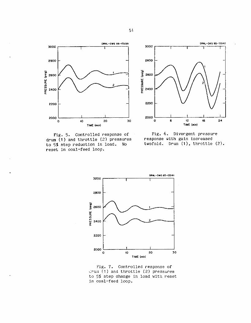
QRNL-OW0 85-43334
2600
2000 2200 0 1 40 20 30
TIME (mid
Fig. 5. C o n t r o l l e d r e s p o n s e of drum ( ? ) and t h r o t t l e ( 2 ) p r e s s u r e s t o 5% S t e p r e d u c t i o n i n load. No reset i n coal-feed loop .
3000
2600
- .P t: 2600
a
p 2400 n
- w 3 in
220a
2000
2800 - - a .- g 2600 I
u
W K a
2400 - P
2200 -
2000 1 I I I I I 0 6 42 18 24
TIME (mid
Fig. 6. Divergent p r e s s u r e r e sponse with g a i n i n c r e a s e d twofold. Drum ( l ) , t h r o t t l e ( 2 ) .
ORNL-DWG 85-13344
0 40 20 30 TIME (mid
-. r i g . 7. C o n t r o l l e d r e sponse of Clnum f t ) and t h r o t t l e ( 2 ) pressures t o 5% s t e p change i n load w i t h reset i n coa l - f eed loop.

Table 6. P r i n c i p a l system heat csyaci t ies expressed i n f u l l power minutes aP stored heat --- _I-
B o i l e r (metal and water) 3
Primary SK 2
Secondary SM 0.5
Preheater 1.5
Bed 6
Condenser 2
Total. 15
s imula t ed p l a n t , tlag - 2-3 min. This p a r t i c u l a r l a g is unique t o
f lu id ized-bed b o i l e r s , and i ts impact on p l a n t c o n t r o l needs t o be
s t u d i e d
The effects of bed c a p a c i t y were analyzed i n part by the r e a c t i o n
cu rve method i n which the c o n t r o l loop far f u e l demand was opened and a
s t e p r e d u c t i o n o f 1 % was made flmanuallyPP i n coal feed. Curve 1 i n
Fig. 8 shows the r e s u l t i n g decrease i n steam p r e s s u r e as a f u n c t i o n of
time, The o v e r a l l shape o f the curve is s igmoida l , charac te r i s t ic o f a
second-order l a g ( F i g , 8 i n s e r t ) , and tke s e c t i o n of p a r t i c u l a r i n t e r e s t
is t h a t from time zero o u t t o t h e p o i n t of i n f l e c t i o n , shown i n t h e
f i g u r e . E x t r a p o l a t i o n of t h e i n f l e c t i o n - p o i n t slope back t o t he i n i t i a l
p r e s s u r e l i n e is a s t a n d a r d measure of the time l a g (2.7 min here)
between chaxlze of c o a l feed and steam pressure re sponse . T h i s va lue
i n c l u d e s a l A -:,-at capacities ar’, t r a n s p o r t d e l a y s associated w i t h t h e
steam cir’c-it and c o a l feed. 70 determine t h e p a r t a s s o c i a t e d
spec i f ica l ly w i t h bed mass, t h e c a l c u l a t i o n was repeated w i t h the
l imes tone mss mathemat ica l ly reduced t o o n e - f i f t h f u l l va lue ( z e r o
va lue W C U ? ~ cali?,e the computer t o d i v i d e by zero). Curve 2 r e s u l t e d .
The dlfffre?ee between the l a g t,iBes of cu rves 1 and 2 , a d j u s t e d t o
t o t a l 3-q n m w , g i v e s 1.9 min as the lag a s s o c i a t e d w i t h t h e bed heat

2420 /;c"Gi-rr-- 2 . 7 - 4
I
2300 232Q [ \\
a .- la n Y
2360 5 u) rn w
2340
CHARACTERISTIC SIGMOID -
0 2 4 TIME 6 (min) 0 40
Fig. 8, Reaction curve a n a l y s i s of system'time lags. Total. l a g ( 1 1 , l a g w i t h reduced bed m a s s ' ( 2 ) , l ag w i t h reduced bed mass and reduced coal t r a n s p o r t and burnup times ( 3 ) .
capacity. Such lags commonly reduce t h e maximum stable gain s e t t i n g s .
S i n c e speed of r e sponse t e n d s t o d e c l i n e wi th reduced g a i n , lags can
l i m i t au tomat i c c o n t r o l , as, for example, i n f o l l o w i n g r a p i d load
changes. Whether bed l a g is l i m i t i n g here r e q u i r e s f u r t h e r a n a l y s i s ,
s i n c e o t h e r f a c t o r s c o n t r i b u t e t o the proper g a i n s e t t i n g .
The r e a c t i o n - c u r v e optimum g a i n s e t t i n g is computed from the
formula
G QL 1 / L S ,
where L is lag and S is i n f l e c t i o n - p o i n t s l o p e ( ra te of change) . The
optimum, therefore, depends on r a t e of r e sponse S as w e l l as time of

response L. Gaii-13 c a l c u l a t e d from t h i s iildex are 1 .48 from curve 1 w i t h
f u l l bed inass and 1.51 from curve 2 with o n e - f i f t h bed mass. Thus,
w i t h i n t h e accuracy o f t h e method, t h e optimum is l a r g e l y i n s e n s i t i v e t o
t h e l a g a s s o c i a t e d w l t h bed mass. P h y s i c a l l y this means t h a t t h e bed
heat c a p a c i t y no t on ly d e l a y s te inperature s i g n a l s t o t he steam but a l s o
acts as a b a l l a s t o r f i l t e r t h a t a t t e n u a t e s them. Mhile l a g s
n e c e s s i t a t e reduced g a i n , f i l t e r i n g r e q u i r e s i n c r e a s e d g a i n t o ma in ta in
s u i t a b l e c o n t r o l , and t h e two bed e f f e c t s tend t o cance l . Such an
i n s e n s i t i v i t y of' g a i n s e t t i n g t o bed mass could be p a r t i c u l a r l y
s i g n i f i c a n t i n s i t u a t i o n s where b?d l e v e l (mass) is v a r i e d f o r l oad
fo l lowing ; the c o n t r o l l e r would t end t o remain tuned i r r e s p e c t i v e o f bed
l e v e l e
Two important d e l a y s a s s o c i a t e d w i t h the f u e l are i ts t r a n s p o r t
time t o t h e f u r n a c e and t h e burnup time c o n s t a n t of crushed coal
p a r t i c l e s , These d e l a y s may impact c o n t r o l somewhat d i f f e r e n t l y than
t h e bed d e l a y . To show this, both c o a l d e l a y s were reduced from f u l l
va lue (15 s each i n curve 2 , Fig. 8 ) t o one -F i f th va lue (curve 3 ) . The
d i f f e r e n c e i n l a g between cu rves 2 and 3 is the expec ted 0.5 min sum o f
the two. The remain ing 0.8 min d e l a y o f curve 3 is the sum of a l l o t h e r
capac i t ance d e l a y s i n t he s teamhater c i r c u i t (e .g . i n t h e b o i l e r metal
and water).
In t h e case o f t h e bed d e l a y , cu rves 1 and 2 have d i f f e r e n t s l o p e s
such t h a t t he s h o r t e r d e l a y o f a smaller bed mass was compensated by
inc reased r e sponse r a t e ( s l o p e ) , and the c o n t r o l l e r g a i n s e t t i n g ,
i n v e r s e l y p r o p o r t i o n a l t o t h e p roduc t , remained e s s e n t i a l l y independent
of bed mass. For t h e c o a l d e l a y s , however, cu rve 3 w i t h reduced d e l a y
has t h e same s l o p e as curve 2 w i t h f u l l d e l a y ; the optimum g a i n is
t h e r e f o r e reduced by t h e r a t i o of t h e l a g s (about 50%). Typica l of
c o a l - f i r e d p l a n t s , t h e A F B C ' s r a t e of au tomat i c r e sponse t o load change
may be r e s t r i c t ed by d e l a y s i n c o a l t r a n s p o r t and burnup (among o t h e r
t h i n g s 1. D e r i v a t i v e c o n t r o l a c t i o n may add compensating phase lead t o these
l a g s . Though f r e q u e n t l y n o t i nc luded i i l conven t iona l c o n t r o l s , t h e

d e r i v a t i v e mode may be a p p r o p r i a t e i n a f l u i d i z e d - b e d p l a n t t o boost. i ts
rate of response. . The s o l i d cu rve i n Fig. 9 shows t h e damped pressure
re sponse w i t h optimum g a i n , r e se t , and derivative. With t h e deqlivativc
mode t h e n t u r n e d o f f (dashed c u r v e ) , t h e same g a i n is t o o h i g h , and t h e
o s c i l l a t i o n is d i v e r g e n t . The s t a b i l i z i n g phase lead ( the time
d i f f e r e n c e between ne ighbor ing peaks o f t he two c u r v e s ) is about 1 min.
I n t h i s case, t he d e r i v a t i v e a l l o w s approximate ly 50% more g a i n and an
i n c r e a s e d r a t e o f l oad change i n a u t o c o n t r o l .
5.4 LOAD FOLLOWING
The model was used t o i n v e s t i g a t e t h e ra te and magnitude o f load
v a r i a t i o n t h a t t h e p l a n t can be expec ted t o fo l low and t o de te rmine t h e
e f f e c t s of c e r t a i n o p e r a t i o n a l strategies on load - fo l lowing c a p a b i l i t y .
Two t y p e s o f l oad change were cons ide red : a b r u p t , s t e p - l i k e change , and
smoother , ramp change.
5.4.1 Abrupt Change
S t a r t i n g a t f u l l power, a 5% s t e p r e d u c t i o n was made i n c o o l i n g a i r
flow ( l o a d ) a t t he condenser . The c o n t r o l system o p e r a t e d t o ma in ta in
s e t p o l n t s . F igu res 1 Oa through 1 Qe show p l a n t r e sponse . Most variables
are h e l d w i t h i n nominal c o n t r o l range . Bed temperature ( F i g . loa, upper
c u r v e ) e x p e r i e n c e s an i n i t i a l d rop of about 50°F with r ecove ry i n 8 min.
Main steam temperature (F ig . loa , lower c u r v e ) remains nea r s e t p o i n t .
Sulphur c a p t u r e (Fig. l o b ) is c l o s e l y c o n t r o l l e d by modest v a r i a t i o n of
l imes tone feed ( F i g . 1Oc).
The l i m i t i n g v a r i a t i o n is steam p r e s s u r e . Main steam (F ig . 10d,
lower c u r v e ) e x p e r i e n c e s an i n i t i a l overshoot of about 115 p s i . That
t h e c o n t r o l l e r is hav ing d i f f i c u l t y i n ho ld ing s team pressure is e v i d e n t
from t h e swing i n c o a l supply (F ig . 10e). The steam-pressure c o n t r o l l e r
is tuned t o fu l l -power c o n d i t i o n s and has the h ighes t s table
p r o p o r t i o n a l g a i n s e t t i n g as well as maximum de r iva t ive a c t i o n t o

2700
G .- 2500 M ia
w 0: 9
w
v
; 2300 a n
2108
1900
56
ORNL-DIG e543343
/ r-1 k----8 i
'
I 1 I 1 I
Fig . 9. Effect of adding d e r i v a t i v e a c t i o n t o coa l - feed c o n t r o l .
compensate RC and t r a n s p o r t lags. In s h o r t , the c o n t r o l l e r is being
d r i v e n as hard as it can be. These r e s u l t s s u g g e s t , therefore, tha t i f
steam pressure is t o be he ld t o w i t h i n a few percentage p o i n t s (commonly
about 2 % ) of s e t p o i n t , s h a r p changes i n l o a d w i l l be l i m i t e d t o
approximate ly 5% magnitude.
5.4.2 Ramp Change
In pract ice , load changes are t y p i c a l l y rather smooth ramps of
va ry ing s t e e p n e s s and d u r a t i o n , The n e x t series of c a l c u l a t i o n s
c o n s i d e r s how f a s t a ramp the p l a n t can be expec ted t a fo l low w i t h the
p r e s e n t c o n t r o l l e r s . O p e r a t i a n a l s t r a t e g y is a major f a c t o r i n t h i s
d e t e r m i n a t i o n , and two possible s t ra tegies w i l l be examined, For
r e a s o n s d i s c u s s e d l a t e r , it w i l l emerge t h a t a key factor i n
load - to l lowing c a p a b i l i t y w i l l be t h e e x t e n t t o which the d i s t r i b u t e d

57
ro
4500 U
w Q: a
Q: w 2 4300
!k 4100
J a $ 0.4 6 8a ab 0.2 d
LL,
900 0 18 20 30
TIME ( m i d 0 IO 20 3
TiME (rnin)
Fig. loa. Effect on system v a r i a b l e s of 5% s t e p r e d u c t i o n i n load. Temperature: bed ( 1 1 , t h r o t t l e (2 ) .
5
2 a 4 a I-
0 0 io 20 30
TIME (min)
3000
2800
2600
2400
2200
2000
Fig. 1Oc. Limestone feed. Fig. 1Od. Steam pressure. D r u m ( l ) , t h ro t t l e ( 2 ) .

58
I8 20 30
Fig. 10e. Coal feed.
( p o s i t i o n dependent ) r a t i o o f f u e l feed (heat s u p p l y ) t o o p e r a t i n g heat
t r a n s f e r surface (heat s i n k ) can be he ld c o n s t a n t across the bed.
A proposed mode of o p e r a t i o n of AFBC p l a n t s ca l l s for heat t r a n s f e r
surface t o be removed from s e r v i c e f o r load- fo l lowing purpxes by
s h u t t i n g down (s lumping) bed compartments. If 3 compartment 's f r a c t i o n
of t o t a l heat, g e n e r a t i o n is, f o r example, me- - fo l r r th , t h e load and c o a l
f eed will f i rs t be decreased by t h i s amount, and then a compartment w i l l
he removed from s e r v i c e . Thus, fuel. r e d u e t : o n and removal of heat
t r a n s f e r surface occur s e q u e n t i a l l y .
This s e q u e n t i a l s t r a t e g y was i n v e s t i g a t e d by a s i m u l a t i o n i n which
load was reduced by 25% over an i n t e r v a l of 33 min (a ramp of
0.75%/min), and then a compartment r e p r e s e n t i n g 25% o f t h e bed was s h u t
down. The model. a l l ows b o i l e r and s d p e r h e a t e r s u r f a c e t o be removed i n
any p r o p o r t i o n ; i n these s t u d i e s , t o e r3am f r a c t i o n (0.25) of each was
removed e

59
The r m p e d r e d u c t i o n i n condenser c o o l i n g ( l o a d demand) is shown i n
F i g . lla. Mainsteam f low, power g e n e r a t i o n , c o a l f e e d , and s u p e r f i c i a l
v e l o c i t y (Figs . l l b th rough l l e ) 3mOQthly f o l l o w demand down t o 75% load.
The i n i t i a l p r e s s u r e ove r shoo t ( F i g . 1 1 f ) is 55 p s i . Bed t empera tu re
(F ig . l l g ) d e c l i n e s a lmost 2 0 O O F because n o n l i n e a r changes i n steam f low
and heat t r a n s f e r c o e f f i c i e n t s cause a 5% i n c r e a s e i n the p s a p o r t i o n of
gene ra t ed heat that is removed i n the bed v e r s u s t h e above-bed
s u p e r h e a t e r .
t r a n s f e r that o f t e n occur s i n b o i l e r s w i th s u p e r h e a t e r s .
I n t h i s , t he p l a n t e x h i b i t s t h e tendency of s h i f t i n g heat
The s t r o n g l y t empera tu re s e n s i t i v e SO, capture e x p e r i e n c e s a
d e c l i n e from 85% t o 70% removal ( F i g . 41h) as a r e s u l t of the subopt imal
bed t empera tu re . To ma in ta in t h i s l e v e l of SO, removal , t h e
SO, c o n t r o l l e r i n c r e a s e s l i m e s t o n e f e e d t o a peak Ca/S r a t i o of
9 (F ig . l l i ) . Limestone f e e d a t t h e peak is 15% greater t h a n coal feed
and f o r a l l p r a c t i c a l purposes is probably near the l i m i t of t h e c o n t r o l
r ange .
Various c o n t r o l v a l v e s e t t i n g s are shown i n F ig . l l j . T h i r t y
minutes i n t o t he t r a n s i e n t , steam temperature c o n t r o l by spray-water
r e g u l a t i o n goes m a r g i n a l l y o u t of the c o n t r o l range f o r a s h o r t time.
To p reven t i n t e g r a l windup, t he c o n t r o l l e r a u t o m a t i c a l l y f r e e z e s reset
a c t i o n u n t i l the t empera tu re r e t u r n s t o c o n t r o l r ange .
A t 33 min, when the demand l e v e l s o f f a t 75% of f u l l l o a d , a
shutdown of one-quar te r of t h e bed is effected. Removal of bed heat
t r a n s f e r s u r f a c e from o p e r a t i o n is made t o occur by compartment s lumping
ove r a pe r iod of 25 rnin (F ig . I l k ) . Even a t t h i s ave rage e f f e c t i v e
removal ra te of on ly l%/min , the s lumping a c t i o n causes t he steam
p r e s s u r e ( F i g . llf) t o nosedive below s e t p o i n t by about 120 p s i .
Thereafter, the sys t em o s c i l l a t e s one o r two c y c l e s , and s e t p o i n t s are
r e s t o r e d about 30 min a f t e r s lumping is i n i t i a t e d . During t h e i n i t i a l
l o a d decrease, when c o a l feed is reduced , t h e r a t i o of f u e l s u p p l y t o
heat t r a n s f e r area (denoted the f u e l - t o - s u r f a c e r a t i o ) is lowered.
Because of bed c i r c u l a t i o n , the lower r a t i o occur s more o r less
uni formly a c r o s s t h e bed. Then, when a compartment is s h u t down, the
o r i g i n a l r a t i o is r e s t o r e d i n t he p o r t i o n of the bed s t i l l in o p e r a t i o n ,
T h i s f l u c t u a t i o n i n t he f u e l - t o - s u r f a c e r a t i o d i s t r i b u t i o n , coupled wi th

40
30
48
30 6 20 40 6 20 40
Fig, l l a . E f f e c t on system Fig. l l b . Main steam flow. v a r i a b l e s of 25% runback of l o a d a t ra te of 0.75%/min, w i t h bed slumping af ter runback. Condenser c o o l i n g a i r ( l o a d ) .
20
I
4
8
Fig . l l c . Power g e n e r a t i o n . Total pomr ( 1 ) , e v a p o r a t o r (21 , bed s u p e r h e a t e r (31, pr imary s u p e r h e a t e r (4).
c \ a v
0 d Lb
7006
6000
5000
4000
3000
Fig. l l d . Coal feed.

16 3000
2800 5 .cI 8, cb .- u)
c
r 2 4 !a
t 3 3
3 w 2
2600 a
2 2480
Y
kl r
0
w 0:
w LL 2200 t
0 2000 0 20 40 60
TIME (rnin) TIME (rain)
Fig. l l e . S u p e r f i c i a l v e l o c i t y . Fig. l l f . Steam p r e s s u r e . Drum (11, t h ro t t l e (21,
4700
c e 1500 Y
W (t: Is 5 4300 M w a L f 1100
900 20 40 60 8
TIME (min)
k! 0.8 3 #- a 5 0.6 -I a 0 0.4 I- 0 g 0.2 1
Fig. l l g . Temperature. bed (11, Fig . l l h . SO, c a p t u r e .
t h r o t t l e ( 2 ) .

6 2
1.
1.
4.2
4.8
0x4
0.6
6.4
8.2
Q 0 20 44) 60 o 20 40 60
Fig. 1 1 i . Limestone feed. Fig. l l j . Con t ro l va lve s e t t i n g s . FD damper (1 1, I D damper (21, t h r o t t l e ( 3 3 , spraywater ( 4 ) .
Q
Fig. I l k . Fkactlon of bed f l u i d i z e d and heat transfer s u r f a c e a c t i v e .

s u b s t a n t i a l heat capacities of t h e bed and p r e s s u r e p a r t s , u p s e t s t h e
t empera tu re d i s t r i b u t i o n . The magnitude of t h e ensu ing d i s t u r b a n c e is a
f u n c t i o n of t h e r a t e of bo th t he l o a d v a r i a t i o n and t h e compartment
shutdown o p e r a t i o n . Apart from any o t h e r r e s t r i c t i o n s , these r e s u l t s
i n d i c a t e t h a t au tomat i c l o a d f o l l o w i n g by s e q u e n t i a l man ipu la t ion of
c o a l feed and heat t r a n s f e r surface w i l l be l i m i t e d t o s u s t a i n e d ramps
of less t h a n about l % / m i r a .
An improved mode of o p e r a t i o n is t o vary c o a l f e e d and heat
t r a n s f e r s u r f a c e s i m u l t a n e o u s l y , such that their r a t i o remains
c o n t i n u o u s l y f i x e d throughout t h e bed. Two p o s s i b l e ways may be c i t ed ,
F i r s t , s i n c e material c i r c u l a t i o n is a f u n c t i o n of void f r a c t i o n , which
i n t u r n is a f u n c t i o n of s u p e r f i c i a l v e l o c i t y , modulat ion of compartment
air v e l o c i t y may p o s s i b l y p rov ide t he basis f o r r e g u l a t i o n of c o a l
i n f i l t r a t i o n and t h e r e b y t h e effect ive amount of heat t r a n s f e r s u r f a c e ,
A second method of m a i n t a i n i n g a ba lanced f u e l - t o - s u r f a c e
d i s t r i b u t i o n is by con t inuous v a r i a t i o n of t he f lu id i zed -bed mass and
h e i g h t t o expose s u r f a c e as necessa ry .
t y p e of o p e r a t i o n , the p rev ious ramp (25% r e d u c t i o n i n l o a d a t
0.75%/min) was repeated, and the same s ta te v a r i a b l e s are shown i n
F i g s . 12a through 12k. The improvement i n c o n t r o l is e v i d e n t , Most
I n a comparat ive s t u d y of t h i s
v a r i a b l e s remain so c l o s e t o s e t p o i n t tha t t he d e v i a t i o n c a n ' t be read
from t h e c u r v e s . P r e s s u r e ( F i g . 1 2 f ) v a r i e s less t h a n 20 p a i l and bed
t empera tu re (F ig . 128) changes on ly l l ° F . Sulphur removal (F ig . 12h)
remains v i r t u a l l y a t s e t p o i n t . I n c o n t r a s t w i t h the p rev ious s p i k e d
l imes tone feed, t h e calcium-to-sulphur r a t i o now remains a t nominal
va lue throughout l o a d r e d u c t i o n ( F i g . 121) . S imul taneous man ipu la t ion
of c o a l feed and h e a t - t r a n s f e r s u r f a c e m a i n t a i n s a ba lanced d i s t r i b u t i o n
of heat p roduc t ion and removal a c r o s s the bed and p r e s s u r e parts and
minimizes the t empera tu re t r a n s i e n t s tha t d i s t u r b e d t h e system under
s e q u e n t i a l o p e r a t i o n .
I n a c o n v e n t i o n a - p l a n t , b o i l e r heat t r a n s f e r c o e f f i c i e n t s are a
f u n c t i o n of gas v e l o c i t y , and d i s t r i b u t i o n of heat t r a n s f e r may be
c o n t r o l l e d by smooth v a r i a t i o n of gas v e l o c i t y , dampel-s, and gas
r e c i r c u l a t i o n . I n zn AFBC, t h e bed heat t r a n s f e r c o e f f i c i e n t is l a r g e l y

64
I I
8 20 40 60 TIME (mid
Fig . 12a. Effect on s y s t e m v a r i a b l e s of 25% runback of l o a d a t 0.75%//min, w i t h v a r i a b l e bed h e i g h t . Condenser c o o l i n g a i r ( l o a d ) .
28
0 0 20 48 68
7000
4060
3000
0 20 40 60 TIME (mid
P i g . 12b, Main steam flow.
0 28 40 6 0
Fig . 12c. Power g e n e r a t i o n . Fig. 12d. Coal f e e d . Total power ( 1 1, e v a p o r a t o r (21, bed s u p e r h e a t e r (31, primary s u p e r h e a t e r (4).

65
ORML-DWG 85-43350 3006) 6
5
4
3
2
i
2800
2600
2400
2200
2000 0 2 0 40
TIME (mid 0 20 4 0
TIME (mid 60 6
Fig. 12f. Steam pressure. Drum (11 , t h ro t t l e (2 ) .
Fig. 12e. Superficial velocity.
I .Q I I 4 w 5 0.8 n
1500 I- Q ff 0.6
fz 1300 a w a s
1100
4 0.4 P
I
k, 2 0.2
- 2
I
L 900 0 20 40
TIME (min) 0
Fig.
60
( 1 1,
20 40 TIME (rnin)
0
Fig. 128. t h ro t t l e (2) .
Temperature. bed 12h. SO, capture.

3 2 4 I
- I
0 - I .
0 20 40 60 0 20 40 60 TIME (mid
Fig. 1 2 i . Limestone feed. Fig. 1 2 j . Control v a l v e set t ings. Throttle ( 1 ), FD damper (21, I D damper (31, spraywater (4).
I .0
0.8
Q 0.6
2
U w U
W
5i 0.4 d W a
0.2
0 0 20 40
Fig. 12k. Fraction of bed fluidized and heat t ransfer supface active.

i n s e n s i t i v e t o gas v e l o c i t y , and the slumping of compartments becomes a
c o u n t e r p a r t o f dampering t h a t may i n t r o d u c e d i s t u r b a n c e s n o t p r e s e n t i n
t h e conven t iona l p l a n t . Any procedure f o r c o n t i n u o u s l y m a i n t a i n i n g t h e
desired heat d i s t r i b u t i o n i n the bed has the n e t e f f e c t o f a t t e m p t i n g t o
o p e r a t e i t , i n t h i s r e s p e c t , more l i k e a conven t iona l p l a n t .
A s i m u l a t i o n was run t o de t e rmine t h e maximum s u s t a i n e d ramp t h a t
the modeled AFBC can a u t o m a t i c a l l y fo l low w i t h s imul t aneous manipula t ion
o f c o a l feed and heat t r a n s f e r surface. b a d was reduced 25% i n
5 min. The r e s u l t s are shown i n Figs. 13a th rough l 3 k . There is an
i n i t i a l p r e s s u r e e x c u r s i o n of abou t 100 p s i . Other v a r i a b l e s remain
well c o n t r o l l e d . This s i m u l a t i o n suggests that a p r o p e r l y o p e r a t e d
f lu id i zed -bed p l a n t may be able t o a u t o m a t i c a l l y fo l low ramps of up t o
about 5%/min, which is c o m p e t i t i v e w i t h l e a d i n g conven t iona l and nuc lea r
p l a n t s .

68
30 1
Fig, 13a. Maximum load- fo l lowing c a p a b i l i t y (5%/rnin) u s i n g v a r i a b l e bed h e i g h t . Condenser c o o l i n g a i r ( l o a d ) .
A c a s? 3: 0 J LI
v
0 20 4 TIME (rnin)
Fig 13c. Power g e n e r a t i on , T o t a l power ( l ) , e v a p o r a t o r (2 ) , bed s u p e r h e a t e r ( 3 ) , pr imary s u p e r h e a t e r ( 4 ) .
70
60 A c \ D v
50
d LL
4
30 0 20 40
TIME (mid
Fig , l 3b . Main steam flow.
7000
6060
5QQO
3000
Fig. 136. Coal f e e d .

ORNL-DWG 85-93353 6
5
4
3
2
I
0 0 20 40 60
TIME (mid
Fig. l3e. S u p e r f i c i a l v e l o c i t y .
1700
n
1500 W 3 a $ 1300
1 w 1400 I-
900
2 r
0
Fig. 13g. t h r o t t l e (2).
20 40 TIME (mid
60
Temperature. Bed ( 1 ) ,
3008
2800
2600
2400
2200
2000 0 20 40
TIME (mid 60
Fig. 1 3 . Steam p r e s s u r e . Drum (11, t h r o t t l e ( 2 ) .
W Q: 3 I-
0
J
z #- 0
LL
n a
a 9
a a
i .0
0.8
0.6
0.4
0.2
0 0
Fig.
20 40 TIME ( m i d
l 3h . SO, c a p t u r e .
60

70
IO I .6
0 20 40 60
Fig. i 3 i . Limestone feed. Fig. 139. Control va lve set t ings. Throttle (11, PD damper (21, I D damper ( 3 1 , spraywater ( 4 ) .
I .o
0.8 a a
2
w 0.6
w
5 0.4 d W U
0.2
0 a 4 60
Fig. l 3 k . Fraction of bed fluidized and heat t ransfer surface active e

ACKNOWLEDGMENT
This work was funded in part by the Tennessee Valley Authority.
71

BEFERENCES
1. A. Ray, D. A. Berkowitz, and V. Sumaria, "Mathematical Modeling and Digital Simulation of the MERC Component Test and Integration Unit," MTR-3447, May 1977.
2. J . R. S. Thorn, W. M. Walker, T. A. Fallon, and G. F. S. Reising, "Boiling in Subcooled Water During Flow Up Heated Tubes or Annuli," Proc. Inst. Mech. Eng. 3C180:226 (1965-66).
3. Babcock and Wilcox, Steam/Its Generation - and Use, 39th ed., 1978, pp. 4-10.
4. F. W. Dittus and L. M. K. Boelter, Univ. of Calif. Publ. Eng. 2:443 (1930).
5. J . P. Holman, Heat Transfer, 4th ed., McGraw-Hill., 1976, p. 180.
6. Babcock and Wilcox Company, Steam/Its Generation and Use, 39th ed., 1978, p. 6-2.
7. T. E. Dowdy et al., "Summary Evaluation of' Atmospheric Pressure Fluidized Bed Combustion Applied to Electric Utility Large Steam Generators," EPRI FP-308, Vol. 2, Appendix 6. Electric Power Research Institute, Palo Alto, Calif., 1976.
8. R. P. Apa et al., "6- x 6-ft Atmospheric Fluidized-Bed Combustion Development Facility and Commercial Utility AFRC Design Assessment,'' EPRI CS-2930, Interim Report, Electric Power Research Institute, Palo Alto, Calif., March, 1983.
9. D. Merrick and J. Highley, AICHE Symposium Series 70, 137, 366-378 (1974).

APPENDIX
The f o l l o w i n g thermodynamic c o r r e l a t i o n s were d e r i v e d from s t a n d a r d
steam t a b l e s for t h e s i m u l a t e d p l a n t operating r a n g e , w i t h t h r o t t l e
p r e s s u r e of 2600 p s i g .
Superhea ted steam:
S a t u r a t e d steam and water:
Td = 541.1 + 2 2 . 8 ~ ~ - 0 .812~ ;
hs = 1242 - 2 1 . 1 ~ ~ + 0.174~:
u = 734 + 6 . 7 6 ~ ~ - 0.363~: S
u = 512 + 2 4 . 9 ~ ~ - 0.755~: W
= 48.8 - 2 . 0 8 ~ ~ + 0.0322~: PW
hw 490 + 4 0 . 4 ~ ~ - 1.16~:
Subcooled water:
( A . 5 )
(A.6)
( A . 7 )
( A . 8 ;
( A . 9 )
(A.10)
( A . 1 1 )
hf = -110 + 1.2Tf
73
(A.12)


ORNL /TM-982 1
INTERNAL DISTRIBUTION
1. R. A. Bradley 2. B. G. Eads 3. D. N. Fry 4. F. R. Mynatt
5-9. 0. L. Smith 10. R. S. S tone 11. R. S. W i l t s h i r e 12. J. B. Ball (Advisor ) 13. M . J. Kopp (Advisor ) 14. P. F. McCrea (Advisor )
15. H. M. Paynter (Advisor ) 16-17. Central Research L i b r a r y . 18. Y-12 Document Reference
S e c t i o n 19. I & C P I P C
22. Labora tory Records, ORNL RC 23. ORNL Pa ten t S e c t i o n
20-21. Labora tory Records
EXTERNAL DISTRIBUTION
24.
25. 26.
27-56.
Assistant Manager f o r Energy Research and Development, DOE-ORO, Oak Ridge, TN 37831 Manager, O f f i c e of Fossil Energy, DOE, Washington, DC 20545 Director, DOE Morgantown Energy Research Cen te r , P.O. Box 800, Norgantown, WV 26506 Office of Scient i f ic & Technica l In fo rma t ion , Oak Ridge, TN 37831