
DYNA 8000, 8200 & 8400 Series Electronic Governor · PDF fileWoodward Governor Company...
32
Installation & Operation Manual DYNA 8000 DYNA 8200 DYNA 8400 DYNA 8000, 8200 & 8400 Series Electronic Governor Systems Manual 36569
Transcript of DYNA 8000, 8200 & 8400 Series Electronic Governor · PDF fileWoodward Governor Company...

Installation & Operation Manual
DYNA 8000 DYNA 8200 DYNA 8400
DYNA 8000, 8200 & 8400 Series
Electronic Governor Systems
Manual 36569
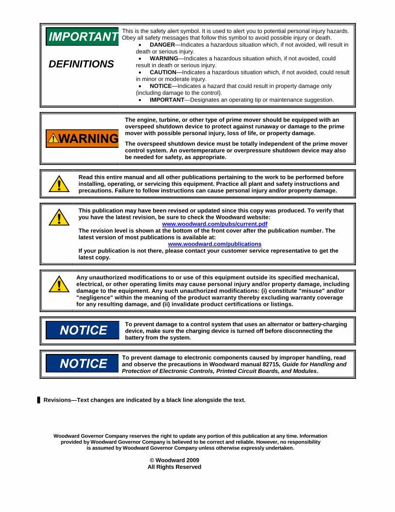
DEFINITIONS
This is the safety alert symbol. It is used to alert you to potential personal injury hazards. Obey all safety messages that follow this symbol to avoid possible injury or death.
DANGER—Indicates a hazardous situation which, if not avoided, will result in
death or serious injury.
WARNING—Indicates a hazardous situation which, if not avoided, could
result in death or serious injury.
CAUTION—Indicates a hazardous situation which, if not avoided, could result
in minor or moderate injury.
NOTICE—Indicates a hazard that could result in property damage only
(including damage to the control).
IMPORTANT—Designates an operating tip or maintenance suggestion.
The engine, turbine, or other type of prime mover should be equipped with an overspeed shutdown device to protect against runaway or damage to the prime mover with possible personal injury, loss of life, or property damage.
The overspeed shutdown device must be totally independent of the prime mover control system. An overtemperature or overpressure shutdown device may also be needed for safety, as appropriate.
Read this entire manual and all other publications pertaining to the work to be performed before installing, operating, or servicing this equipment. Practice all plant and safety instructions and precautions. Failure to follow instructions can cause personal injury and/or property damage.
This publication may have been revised or updated since this copy was produced. To verify that you have the latest revision, be sure to check the Woodward website:
www.woodward.com/pubs/current.pdf The revision level is shown at the bottom of the front cover after the publication number. The latest version of most publications is available at:
www.woodward.com/publications If your publication is not there, please contact your customer service representative to get the latest copy.
Any unauthorized modifications to or use of this equipment outside its specified mechanical, electrical, or other operating limits may cause personal injury and/or property damage, including damage to the equipment. Any such unauthorized modifications: (i) constitute "misuse" and/or "negligence" within the meaning of the product warranty thereby excluding warranty coverage for any resulting damage, and (ii) invalidate product certifications or listings.
To prevent damage to a control system that uses an alternator or battery-charging device, make sure the charging device is turned off before disconnecting the battery from the system.
To prevent damage to electronic components caused by improper handling, read and observe the precautions in Woodward manual 82715, Guide for Handling and Protection of Electronic Controls, Printed Circuit Boards, and Modules.
Revisions—Text changes are indicated by a black line alongside the text.
Woodward Governor Company reserves the right to update any portion of this publication at any time. Information provided by Woodward Governor Company is believed to be correct and reliable. However, no responsibility
is assumed by Woodward Governor Company unless otherwise expressly undertaken.
© Woodward 2009 All Rights Reserved

Manual 36569 DYNA 8000 Electronic Governor Systems
Woodward 1
Contents
ELECTROSTATIC DISCHARGE AWARENESS ................................................. 2
CHAPTER 1. GENERAL INFORMATION .......................................................... 3 Introduction ............................................................................................................ 3
CHAPTER 2. SPECIFICATIONS ..................................................................... 3 Actuator Specifications .......................................................................................... 3 Actuator Selection Guide ....................................................................................... 3
DYNA 8000 Series Actuators ........................................................................ 4 DYNA 8200 Series Actuators ........................................................................ 6 DYNA 8400 Series Actuators ........................................................................ 6
Controller Selection Guide..................................................................................... 7 Controller Models ........................................................................................... 7 Specification Chart ......................................................................................... 8
CHAPTER 3. INSTALLATION ........................................................................ 9 Controller Dimensions & Wiring Diagram ............................................................ 11 Actuator Dimensions ........................................................................................... 13
DYNA 8000 Series ....................................................................................... 13 DYNA 8200 Series ....................................................................................... 14 DYNA 8400 Series ....................................................................................... 14
CHAPTER 4. CALIBRATION ....................................................................... 15 Switch SW1 and SW2 Adjustments .................................................................... 15 Calibration Procedure for Non-derivative Pot Controllers ................................... 16 Calibration Procedure for Derivative Pot Controllers .......................................... 17
CHAPTER 5. DIAGNOSTICS & TROUBLESHOOTING ..................................... 19
CHAPTER 6. SERVICE OPTIONS ................................................................ 22 Product Service Options ...................................................................................... 22 Woodward Factory Servicing Options ................................................................. 23 Returning Equipment for Repair .......................................................................... 24 Replacement Parts .............................................................................................. 24 Engineering Services ........................................................................................... 25 How to Contact Woodward .................................................................................. 25 Technical Assistance ........................................................................................... 26
Illustrations Figure 1. Isochronous Operation Mode ............................................................. 3 Figure 2. Droop Operation Mode ........................................................................ 2 Figure 3. Installation of Magnetic Pickup ......................................................... 10 Figure 4. Rotary Actuator to Rotary Fuel Pump Linkage ............................... 10 Figure 5. Rotary Actuator to Linear Fuel Pump Linkage ................................ 10 Figure 6. Dimensions & Wiring Diagram for 8270-1072 Controller ............... 11 Figure 7. Wiring Diagram for CE Controllers ................................................... 12
Manual 36569 DYNA 8000 Electronic Governor Systems
Woodward 2
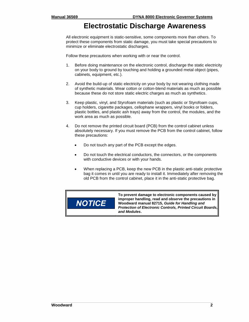
Electrostatic Discharge Awareness All electronic equipment is static-sensitive, some components more than others. To protect these components from static damage, you must take special precautions to minimize or eliminate electrostatic discharges. Follow these precautions when working with or near the control. 1. Before doing maintenance on the electronic control, discharge the static electricity
on your body to ground by touching and holding a grounded metal object (pipes, cabinets, equipment, etc.).
2. Avoid the build-up of static electricity on your body by not wearing clothing made
of synthetic materials. Wear cotton or cotton-blend materials as much as possible because these do not store static electric charges as much as synthetics.
3. Keep plastic, vinyl, and Styrofoam materials (such as plastic or Styrofoam cups,
cup holders, cigarette packages, cellophane wrappers, vinyl books or folders, plastic bottles, and plastic ash trays) away from the control, the modules, and the work area as much as possible.
4. Do not remove the printed circuit board (PCB) from the control cabinet unless
absolutely necessary. If you must remove the PCB from the control cabinet, follow these precautions:
Do not touch any part of the PCB except the edges.
Do not touch the electrical conductors, the connectors, or the components with conductive devices or with your hands.
When replacing a PCB, keep the new PCB in the plastic anti-static protective bag it comes in until you are ready to install it. Immediately after removing the old PCB from the control cabinet, place it in the anti-static protective bag.
To prevent damage to electronic components caused by improper handling, read and observe the precautions in Woodward manual 82715, Guide for Handling and Protection of Electronic Controls, Printed Circuit Boards, and Modules.

Manual 36569 DYNA 8000 Electronic Governor Systems
Woodward 3
Engine Load
Desired Engine RPM
Isochronous Operation Mode
Engine RPM
100%
Chapter 1. General Information
Introduction DYNA 8000, DYNA 8200, and DYNA 8400 governor systems provide engine governing for speed and power control of piston and gas turbine engines or steam and water turbines. The system components are a rotary actuator and an electronic controller, both of which are described further in this manual. The DYNA 8000 and DYNA 8400 hazardous duty actuators are UL listed for Class I, Division 2, Group D, hazardous duty applications that are often encountered in the petroleum or chemical industries. ACTUATOR
The actuator consists of an electromagnet with an iron armature rolling on the center shaft bearings. The actuator is provided with a return spring which balances the magnetic force of the armature. When DC current flows in the coil, the magnetic force moves the armature in the stator and this linear motion is transformed into rotary motion through a crank arm that forms part of the output shaft. CONTROLLER
The electronic controller is the information processing unit of the governor assembly. It contains electronic components which process the input signal from the magnetic pickup to command the engine to the desired speed/RPM set into the controller. Electronic adjustments are available on the controller for field adjusting the unit as necessary. DC POWER SOURCE
The governor system receives its power from a battery or an AC to DC power supply
supplying 12 or 24 Vdc 20% to match the governor voltage. The average operating current consumption is 2.5A to 3.5A and the highest consumption is 14.75A during engine start-up or during a large load change. The power source must be rated above maximum stall current. ISOCHRONOUS OPERATION
Isochronous operation is obtained by setting DROOP potentiometer fully counterclockwise. The DYNA governor is all electric, and it is normally operated in the
isochronous mode; i.e., engine RPM is constant (0.25%) under steady state load conditions, up to the engine's maximum capability, regardless of load on the engine.
Figure 1. Isochronous Operation Mode

Manual 36569 DYNA 8000 Electronic Governor Systems
Woodward 2
DROOP OPERATION
Droop operation is obtained by setting the DROOP potentiometer. Clockwise increases the droop. The amount of droop for a given setting depends on the magnetic pickup frequency and no-load to full-load actuator shaft rotation. A DROOP potentiometer setting of 10 o'clock will give about 4% droop, no load to full load when the pickup frequency is 4260 Hz and actuator shaft rotation is approximately 30° from no load to full load. Lower pickup frequency or smaller shaft rotation results in less droop for the system.
Figure 2. Droop Operation Mode REMOTE SPEED ADJUSTMENT
An optional remote speed selector (DYNS-10000) is available for adjusting engine RPM from up to 90 meters (300 feet.) from the engine. Refer to the electrical wiring schematic shown in Figure 6. The potentiometer can be connected for a narrow (fine) or wide speed range control.
No Load Engine RPM
Adjustable Engine RPM
% of Engine Load
100% 0%
Full Load Engine RPM
Droop Operation Mode
Manual 36569 DYNA 8000 Electronic Governor Systems
Woodward 3
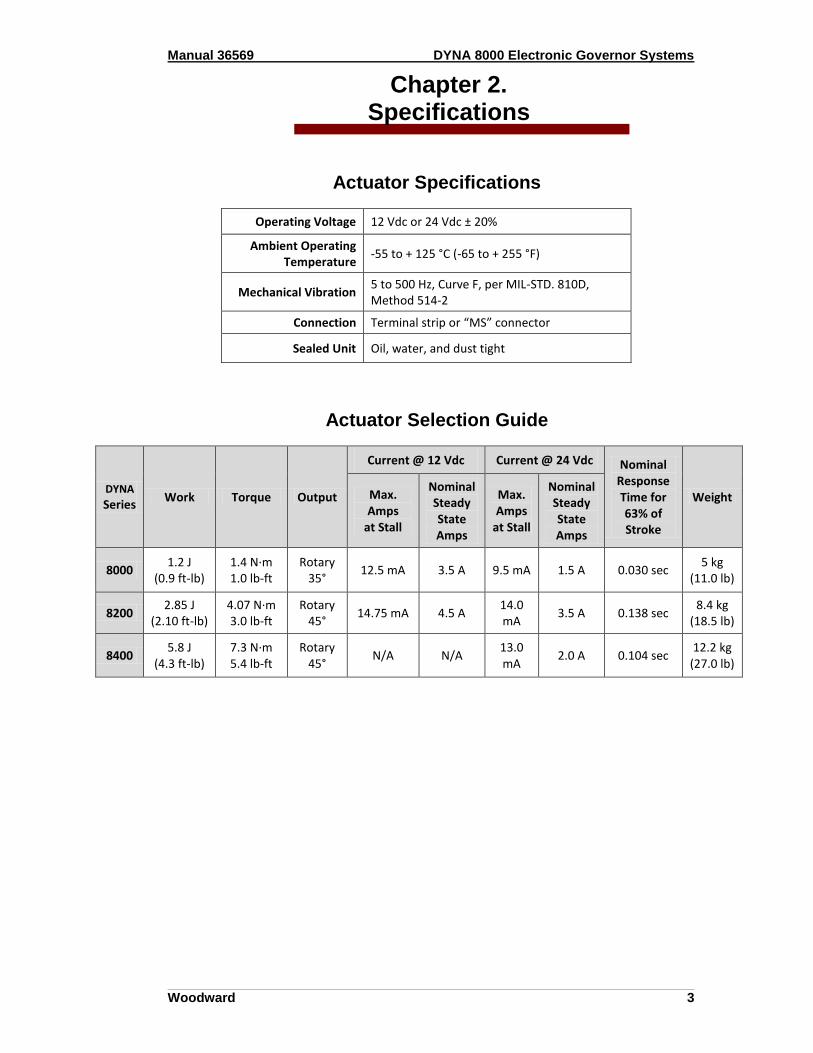
Chapter 2. Specifications
Actuator Specifications
Operating Voltage 12 Vdc or 24 Vdc ± 20%
Ambient Operating Temperature
-55 to + 125 °C (-65 to + 255 °F)
Mechanical Vibration 5 to 500 Hz, Curve F, per MIL-STD. 810D, Method 514-2
Connection Terminal strip or “MS” connector
Sealed Unit Oil, water, and dust tight
Actuator Selection Guide
DYNA Series
Work Torque Output
Current @ 12 Vdc Current @ 24 Vdc Nominal Response Time for 63% of Stroke
Weight Max. Amps
at Stall
Nominal Steady State Amps
Max. Amps
at Stall
Nominal Steady State Amps
8000 1.2 J
(0.9 ft-lb) 1.4 N·m 1.0 lb-ft
Rotary 35°
12.5 mA 3.5 A 9.5 mA 1.5 A 0.030 sec 5 kg
(11.0 lb)
8200 2.85 J
(2.10 ft-lb) 4.07 N·m 3.0 lb-ft
Rotary 45°
14.75 mA 4.5 A 14.0 mA
3.5 A 0.138 sec 8.4 kg
(18.5 lb)
8400 5.8 J
(4.3 ft-lb) 7.3 N·m 5.4 lb-ft
Rotary 45°
N/A N/A 13.0 mA
2.0 A 0.104 sec 12.2 kg
(27.0 lb)
Manual 36569 DYNA 8000 Electronic Governor Systems
Woodward 4
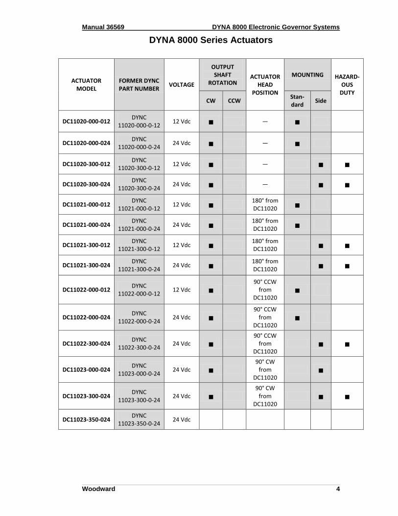
DYNA 8000 Series Actuators
ACTUATOR MODEL
FORMER DYNC PART NUMBER
VOLTAGE
OUTPUT SHAFT
ROTATION ACTUATOR
HEAD POSITION
MOUNTING HAZARD-OUS
DUTY CW CCW
Stan-dard
Side
DC11020-000-012 DYNC
11020-000-0-12 12 Vdc ■ — ■
DC11020-000-024 DYNC
11020-000-0-24 24 Vdc ■ — ■
DC11020-300-012 DYNC
11020-300-0-12 12 Vdc ■ — ■ ■
DC11020-300-024 DYNC
11020-300-0-24 24 Vdc ■ — ■ ■
DC11021-000-012 DYNC
11021-000-0-12 12 Vdc ■
180° from DC11020 ■
DC11021-000-024 DYNC
11021-000-0-24 24 Vdc ■
180° from DC11020 ■
DC11021-300-012 DYNC
11021-300-0-12 12 Vdc ■
180° from DC11020
■ ■
DC11021-300-024 DYNC
11021-300-0-24 24 Vdc ■
180° from DC11020
■ ■
DC11022-000-012 DYNC
11022-000-0-12 12 Vdc ■
90° CCW from
DC11020 ■
DC11022-000-024 DYNC
11022-000-0-24 24 Vdc ■
90° CCW from
DC11020 ■
DC11022-300-024 DYNC
11022-300-0-24 24 Vdc ■
90° CCW from
DC11020 ■ ■
DC11023-000-024 DYNC
11023-000-0-24 24 Vdc ■
90° CW from
DC11020 ■
DC11023-300-024 DYNC
11023-300-0-24 24 Vdc ■
90° CW from
DC11020 ■ ■
DC11023-350-024 DYNC
11023-350-0-24 24 Vdc
Manual 36569 DYNA 8000 Electronic Governor Systems
Woodward 5
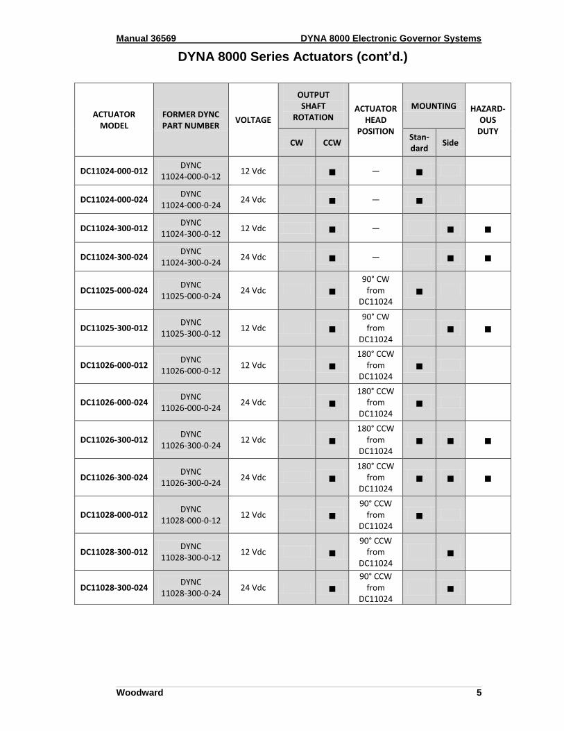
DYNA 8000 Series Actuators (cont’d.)
ACTUATOR MODEL
FORMER DYNC PART NUMBER
VOLTAGE
OUTPUT SHAFT
ROTATION ACTUATOR
HEAD POSITION
MOUNTING HAZARD-OUS
DUTY CW CCW
Stan-dard
Side
DC11024-000-012 DYNC
11024-000-0-12 12 Vdc ■ — ■
DC11024-000-024 DYNC
11024-000-0-24 24 Vdc ■ — ■
DC11024-300-012 DYNC
11024-300-0-12 12 Vdc ■ — ■ ■
DC11024-300-024 DYNC
11024-300-0-24 24 Vdc ■ — ■ ■
DC11025-000-024 DYNC
11025-000-0-24 24 Vdc ■
90° CW from
DC11024 ■
DC11025-300-012 DYNC
11025-300-0-12 12 Vdc ■
90° CW from
DC11024 ■ ■
DC11026-000-012 DYNC
11026-000-0-12 12 Vdc ■
180° CCW from
DC11024 ■
DC11026-000-024 DYNC
11026-000-0-24 24 Vdc ■
180° CCW from
DC11024 ■
DC11026-300-012 DYNC
11026-300-0-24 12 Vdc ■
180° CCW from
DC11024 ■ ■ ■
DC11026-300-024 DYNC
11026-300-0-24 24 Vdc ■
180° CCW from
DC11024 ■ ■ ■
DC11028-000-012 DYNC
11028-000-0-12 12 Vdc ■
90° CCW from
DC11024 ■
DC11028-300-012 DYNC
11028-300-0-12 12 Vdc ■
90° CCW from
DC11024 ■
DC11028-300-024 DYNC
11028-300-0-24 24 Vdc ■
90° CCW from
DC11024 ■
Manual 36569 DYNA 8000 Electronic Governor Systems
Woodward 6
DYNA 8200 Series Actuators
ACTUATOR MODEL
FORMER DYNC PART NUMBER
VOLTAGE
OUTPUT SHAFT
ROTATION ACTUATOR
HEAD POSITION
MOUNTING HAZARD- OUS
DUTY CW CCW
Stan-dard
Side
DC12000-000-012 DYNC
12000-000-0-12 12 Vdc ■ —
DC12000-000-024 DYNC
12000-000-0-24 24 Vdc ■ —
DC12001-000-012 DYNC
12001-000-0-12 12 Vdc ■
180° from DC12000
DC12001-000-024 DYNC
12001-000-0-24 24 Vdc ■
180° from DC12000
DC12002-000-012 DYNC
12001-000-0-12 12 Vdc ■
90° CCW from
DC12000
DC12003-000-024 DYNC
12003-000-0-24 24 Vdc ■
90° CW from
DC12000
DYNA 8400 Series Actuators
ACTUATOR MODEL
FORMER DYNC PART NUMBER
VOLTAGE
OUTPUT SHAFT
ROTATION ACTUATOR
HEAD POSITION
MOUNTING HAZARD-OUS
DUTY CW CCW
Stan-dard
Side
DC14800-000-024 DYNC
14800-000-0-24 24 Vdc ■ † ■ † —
(†) Through output shaft makes available both CW and CCW output.

Manual 36569 DYNA 8000 Electronic Governor Systems
Woodward 7
Controller Selection Guide Any of the controllers listed below can be used on a DYNA 8000, DYNA 8200, or DYNA 8400 actuator. The controllers are categorized as either Derivative Pot or Non-derivative Pot models, depending on their adjustability features.
Controller Input Signal Frequency
Select your controller for the correct input signal frequency range generated by the magnetic pickup at the maximum engine operated (RPM) speed. Use the following formula to convert from RPM to Hertz.
MpuHertzs
ethNumberOfTeEngineRPM
60
Controller Models
CONTROLLER MODEL
FORMER DYNI PART NUMBER
VOLTAGE FREQUENCY CE
MARKED
NON-DERIVATIVE POT MODELS
8270-1021 DYN1-10654-000-0-12 12 Vdc 2500–5000 Hz
8270-1004 DYN1-10654-000-0-24 24 Vdc 2500–5000 Hz
8270-1072 DYN1-10654-001-0-24 24 Vdc 2500–5000 Hz ■
DERIVATIVE POT MODELS
8270-1024 DYN1-10684-000-0-12 12 Vdc 2500–5000 Hz
8270-1073 DYN1-10684-000-0-24 24 Vdc 2500–5000 Hz

Manual 36569 DYNA 8000 Electronic Governor Systems
Woodward 8
Specification Chart
Operating Voltage 12 Vdc or 24 Vdc ± 20%
Ambient Operating Temperature
-40 to +85 °C (-40 to + 180 °F)
Temperature Stability Better than ± 0.5% over a temperature range of -40 to + 75 °C (-40 to + 167 °F)
Output Current
Current Draw w/o Actuator:
Maximum Amps at Stall:
At 12 and 24 Vdc:
Steady State Speed Band
± 0.25%
Adjustments
Non-Derivative Pot Models:
Derivative Pot Models
Mechanical Vibration
Withstands the following vibration without failure or degraded performance: 0.06 inch double amplitude at 5 to 18 Hz; 1 G at 18 to 30 Hz; 0.02 inch double amplitude at 30 to 48 Hz; 2.5 G's at 48 to 70 Hz
Connection Terminal strip
Circuit Boards Boards are covered with a heavy conformal coating for moisture and vibration protection
Sealed Unit Oil, water, and dust tight
Weight 0.863 kg (1.9 lb)
80 mA
13 A
Speed, Gain, Integral, and Droop
Speed, Gain, Integral, Droop, and Derivative

Manual 36569 DYNA 8000 Electronic Governor Systems
Woodward 9
Chapter 3. Installation
The actuator of the governor assembly is mounted on the engine next to the fuel system. The magnetic pickup is normally mounted in the flywheel housing in such a way that it can count the teeth on the starter ring gear. The controller is off-mounted or installed in the engine control panel or cabinet. 1. Mount the actuator on a suitable rigid steel bracket or plate.
Mounting kits are available for particular engines. Please contact your Woodward customer service representative if you require mounting information or a kit.
2. Set up the linkage and rod end bearings as shown in Figures 4 and 5. 3. Install the speed sensor (magnetic pickup) with SAE threads. (Magnetic pickups
with M16x1.5 threads and 14.5 Ø mm tap drills are available.) 4. Remove the inspection cover over the ring gear teeth. (The magnetic pickup should
not be installed in inspection covers.) Gear teeth should be free of burrs, excessive grease, or dirt.
5. Inspect the ring gear housing and pick a location where a 37/64" hole can be drilled
such that the ring gear teeth will pass in front of the pickup pole face. After the 37/64" hole is drilled, use a 5/8-18 starting tap to cut threads for the magnetic pickup, and then run a bottom tap through the hole.
The tapped hole should be drilled as perpendicular as possible over the center of the ring gear teeth.
6. Manually rotate the ring gear until a tooth face is directly in the center of the tapped
hole. Gently turn the magnetic pickup clockwise into the hole until it bottoms on the tooth, and back off 1/4 turn. Tighten the jam nut firmly, maintaining the 1/4 turn position.
7. Mount the controller in the control panel. 8. Connect the wiring as shown in Figure 6 or according to your particular wiring
diagram.

Manual 36569 DYNA 8000 Electronic Governor Systems
Woodward 10
Figure 3. Installation of Magnetic Pickup
Figure 4. Rotary Actuator to Rotary Fuel Pump Linkage
Figure 5. Rotary Actuator to Linear Fuel Pump Linkage
DIAGRAM NOTES
Choose hole in actuator lever which causes actuator to rotate through its maximum rotation to provide minimum to maximum fuel.
Non-linear linkage to actuator is proper for best operation. Provides low GAIN at light loads and high GAIN at heavy loads.
1
2

Manual 36569 DYNA 8000 Electronic Governor Systems
Woodward 11
Controller Dimensions & Wiring Diagram
Dimensions are in mm. Dimensions in brackets [ ] are in inches.
Figure 6. Dimensions & Wiring Diagram for 8270-1072 Controller
DIAGRAM NOTES
Cable A: DK44-XX 90connector (specify length) Cable B: E26-22N (specify length) Cable C— DZ70-004-XX terminal strip (specify length) OR MS connector * Shielded cable – A customer should purchase a cable with a wrapped Mylar supported aluminum foil shield with a drain wire.
** Remote speed potentiometer and 499K ohm resistor is P/N (DYNS-10000). † The 5K remote speed potentiometer can be wired two different ways:
1. As shown by the solid line from the wiper of the 5K potentiometer and then connected to terminal #9 (no resistor required). Adjustable range is approximately
5% at 1800 RPM.
2. As shown by the dashed line from the wiper of the 5K potentiometer through resistor R and then connected to terminal #8. Reducing the value of R increases the remote adjustable speed range.
Manual 36569 DYNA 8000 Electronic Governor Systems
Woodward 12
Figure 7. Wiring Diagram for CE Controllers
The engine, turbine, or other type of prime mover should be equipped with an overspeed shutdown device to protect against runaway or damage to the prime mover with possible personal injury, loss of life, or property damage.
The overspeed shutdown device must be totally independent of the prime mover control system. An overtemperature or overpressure shutdown device may also be needed for safety, as appropriate.
DWG NO. DYN1-10684

Manual 36569 DYNA 8000 Electronic Governor Systems
Woodward 13
Actuator Dimensions
DYNA 8000 Series
Dimensions are in millimeters. Dimensions in brackets [ ] are inches.
DWG NO. DYNC-11020-000-0-XX
Manual 36569 DYNA 8000 Electronic Governor Systems
Woodward 14
DYNA 8200 Series Dimensions are in millimeters. Dimensions in brackets [ ] are inches.
Dimensions are in millimeters.
DYNA 8400 Series Dimensions are in millimeters. Dimensions in brackets [ ] are inches.
DWG NO DYNC-12001-000-0-XX
DWG NO. DYNC-14800-000-0-XX

Manual 36569 DYNA 8000 Electronic Governor Systems
Woodward 15
Top View
Side View “ON”
Side View “OFF”
Chapter 4. Calibration
As mentioned previously, any of the controllers described in Chapter 2 can be used with DYNA 8000, DYNA 8200, or DYNA 8400 actuators. The controllers are categorized as either Derivative Pot or Non-derivative Pot models, depending on their adjustability features, and each category has its own calibration procedure. Follow the calibration instructions relevant to the controller type you have. Model numbers are provided to help you determine the correct calibration procedures to follow.
Switch SW1 and SW2 Adjustments
Switch adjustments are the same for both controller types. These switches allow for fuel response ranges (SW1 for matching either diesel or gas engine dynamics) and actuator selections (SW2 for either DYNA 8000, 8200, or 8400 actuators) SW1 selects one of two integrating rate ranges. The diesel version integrates at twice the rate of the gas version
Set S1 to the OFF position for diesel engine applications.
Set S1 to the ON position for gas/gasoline engine applications.
NOTE: For some diesel engines, better operation may be obtained by placing SW1 in the ON position. If difficulty is experienced in the OFF position, try SW1 ON and recalibrate.
SW2 selects the point at which actuator coil current level causes the integrator limit to be actuated. This level is nominally 6.3A for the DYNA 8000 and 7.3A for the DYNA 8200 and 8400 actuators.
The easiest way to set the switches is to apply pressure
with a small pointed object until the switch clicks into
position.

Manual 36569 DYNA 8000 Electronic Governor Systems
Woodward 16
Calibration Procedure for Non-derivative Pot Controllers
Model Numbers:
8270-1021 (DYN1-10654-000-0-24)
8270-1004 (DYN1-10654-000-0-24)
8270-1072 (DYN1-10654-001-0-24) [CE Marked]
8270-1053 (DYN1-10654-704-0-12)
Connection Information
When using an ILS unit, the remote speed potentiometer may be left connected to the controller as shown. When an ILS unit is used, connect 3-wire shielded cable to terminals 6, 7 and 8. Connect drain shield wire to terminal 10 at the controller only. The other end of drain shield wire is to be cut off and taped.
Calibration Procedures
1. Refer to Figure 6 or Figure 7 before making any adjustments of the potentiometers, DROOP, I, GAIN and SPEED.
2. Turn power OFF to be sure that the engine is not operating.
3. Initial potentiometer settings:
a Set the I adjustment three divisions from zero and the GAIN at the second division from zero.
b For isochronous operation, set DROOP counterclockwise to minimum position as shown in Figure 1.
c For DROOP operation, set DROOP potentiometer clockwise to obtain desired amount of DROOP from no-load to full load. Turning potentiometer clockwise increases DROOP.
If the full 35o
rotation of the actuator shaft is used and the linkage adjusted to use only the active fuel range, the maximum obtainable DROOP would be approximately 12% at full load.
4. Start the engine. 5. Adjust the controller speed potentiometer until the engine is operating at the
desired engine RPM. Clockwise increases engine RPM. 6. If the governor system is unstable, slightly reduce the GAIN setting.
NOTE: Except for the speed adjustment, the potentiometers have internal stops at the 0 and 100% positions.
7. With the engine unloaded, finalize the settings, I and GAIN adjustments as follows:
a Turn the GAIN adjustment clockwise slowly until the actuator lever oscillates. (You may need to disturb actuator lever to cause oscillation.) Reduce the GAIN adjustment slowly counterclockwise until the lever is stable. Upset the lever by hand. If the lever oscillates 3 to 5 diminishing oscillations and stops, the setting is correct.
b If system performance to load changes is satisfactory, omit step (c).
Manual 36569 DYNA 8000 Electronic Governor Systems
Woodward 17
c Reduce the GAIN setting counterclockwise one division. Next, turn the I adjustment fully clockwise while observing the actuator lever. If the lever does not become unstable, upset it by hand. When the lever slowly oscillates, turn the adjustment counterclockwise slowly until the lever is stable. Upset the lever again; it should oscillate 3 to 5 times and then become stable for optimum response.
NOTE: Use whichever settings from steps (b) or (c) provide the best performance.
8. The unit is now calibrated.
Calibration Procedure for Derivative Pot Controllers
Model Numbers:
8270-1024 (DYN1-10684-000-0-12)
8270-1073 (DYN1-10684-000-0-24)
Calibration Procedures
1. Observe that potentiometer settings are adjustable from zero to 100%. Each small division is 10%. The speed potentiometer is 10K, 20 turn.
2. Set SW1 and SW2.
Set switch, S1, for the correct engine:
Set S1 to the OFF position for diesel engine applications.
Set S1 to the ON position for gas/gasoline engine applications. Set switch S2 for the correct actuator:
Set S2 to the "OFF" position for DYNA 8000 actuator
Set S2 to the "ON" position for DYNA 8200 or 8400 actuator. 3. If a remote speed potentiometer is used for narrow range, set to mid range.
4. Initial potentiometer settings:
GAIN 20%
I 20%
D 30%
DROOP Zero
5. For isochronous operation, set DROOP counterclockwise to minimum position as shown in Figures 2 and 3.
6. For droop operation, set DROOP potentiometer clockwise to obtain desired
amount of droop from no-load to full load. Turning potentiometer clockwise increases droop.
7. Start engine (No Load)
8. Adjust the controller speed potentiometer for desired engine speed. 9. Adjust the GAIN potentiometer clockwise until the engine begins to hunt. (If the
engine remains stable at 100% GAIN, physically disrupt the actuator linkage by
Manual 36569 DYNA 8000 Electronic Governor Systems
Woodward 18
hand.) With the engine hunting, turn the GAIN potentiometer counterclockwise until stable.
10. Repeat step 9 for the "D" setting. 11. Repeat step 9 for the "I" setting. 12. The unit is now calibrated.
NOTE: After calibration, it may be necessary to readjust the speed. 13. Conduct the following test:
With the engine operating at rated speed, turn the electric governor off. When engine speed slows to approximately half of rated speed, turn the electric governor back on. Observe the overshoot. If there is a small hunt at steady state, slightly turn the "I" potentiometer counterclockwise until stable. In some cases, 2 to 3 Hz overshoot may be acceptable.
For gas engines, make certain that method used does not put gas in exhaust which might result in an explosion.
If possible, operate the unit through various load ranges up to 100% to ensure stability.
Manual 36569 DYNA 8000 Electronic Governor Systems
Woodward 19
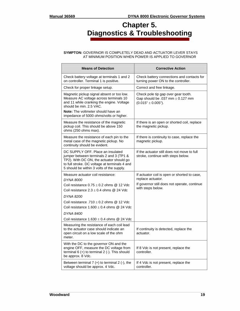
Chapter 5. Diagnostics & Troubleshooting
SYMPTON: GOVERNOR IS COMPLETELY DEAD AND ACTUATOR LEVER STAYS
AT MINIMUM POSITION WHEN POWER IS APPLIED TO GOVERNOR
Means of Detection Corrective Action
Check battery voltage at terminals 1 and 2 on controller. Terminal 1 is positive.
Check battery connections and contacts for turning power ON to the controller.
Check for proper linkage setup. Correct and free linkage.
Magnetic pickup signal absent or too low. Measure AC voltage across terminals 10 and 11 while cranking the engine. Voltage should be min. 2.5 VAC.
Note: The voltmeter should have an
impedance of 5000 ohms/volts or higher.
Check pole tip gap over gear tooth.
Gap should be .037 mm 0.127 mm
(0.015" 0.005").
Measure the resistance of the magnetic pickup coil. This should be above 150 ohms (250 ohms max).
If there is an open or shorted coil, replace the magnetic pickup.
Measure the resistance of each pin to the metal case of the magnetic pickup. No continuity should be evident.
If there is continuity to case, replace the magnetic pickup.
DC SUPPLY OFF. Place an insulated jumper between terminals 2 and 3 (TP1 & TP2). With DC ON, the actuator should go to full stroke. DC voltage at terminals 4 and 5 should be within 3 volts of the supply.
If the actuator still does not move to full stroke, continue with steps below.
Measure actuator coil resistance:
DYNA 8000
Coil resistance 0.75 0.2 ohms @ 12 Vdc
Coil resistance 2.3 0.4 ohms @ 24 Vdc
DYNA 8200
Coil resistance .710 0.2 ohms @ 12 Vdc
Coil resistance 1.600 0.4 ohms @ 24 Vdc
DYNA 8400
Coil resistance 1.630 0.4 ohms @ 24 Vdc
If actuator coil is open or shorted to case, replace actuator.
If governor still does not operate, continue with steps below.
Measuring the resistance of each coil lead to the actuator case should indicate an open circuit on a low scale of the ohm meter.
If continuity is detected, replace the actuator.
With the DC to the governor ON and the engine OFF, measure the DC voltage from terminal 6 (+) to terminal 2 (-). This should be approx. 8 Vdc.
If 8 Vdc is not present, replace the controller.
Between terminal 7 (+) to terminal 2 (-), the voltage should be approx. 4 Vdc.
If 4 Vdc is not present, replace the controller.

Manual 36569 DYNA 8000 Electronic Governor Systems
Woodward 20
SYMPTON: ACTUATOR GOES TO FULL STROKE WHEN DC POWER IS TURNED ON
(ENGINE IS NOT OPERATING)
Means of Detection Corrective Action
Check magnetic pickup leads for proper shielded wire or open shield.
Verify and correct wiring as necessary.
Be sure there is no jumper between terminals 2 and 3.
Verify and correct wiring as necessary.
Failsafe circuit in the controller may be damaged or defective.
Replace controller.
With DC power OFF remove leads at actuator. Check continuity of each terminal to case. There should be no continuity between any terminal and case of the controller.
If continuity is detected, replace the controller.
If remote speed potentiometer has been connected to terminals 6, 7 and 9 of the controller, DISCONNECT THESE LEADS.
Turn DC power ON to the governor if the actuator is now normal. Proceed to Improper operation from Remote Speed Potentiometer Table, Step 1 on the next page.
SYMPTON: IMPROPER OPERATION FROM REMOTE SPEED POTENTIOMETER
Means of Detection Corrective Action
Investigate wiring to remote speed potentiometer for open or shorted circuits.
Check wiring.
If the leads at terminals 6 and 7 to the remote speed potentiometer are reversed, speed control by the remote speed potentiometer will be reversed.
Correct wiring.
Lead wire to remote speed setting potentiometer should be 3-wire shielded cable.
Verify that the drain shield wire is isolated from ground at the potentiometer.
If terminal 7 lead to the remote speed potentiometer is open, engine speed will go high.
Correct the wiring.
If lead 9 (wiper lead to remote potentiometer) is open, there will be no control by the remote speed potentiometer.
Verify and correct wiring.
If lead 6 to the clockwise terminal of the remote speed potentiometer is open, speed will remain at the value set in the controller.
Manual 36569 DYNA 8000 Electronic Governor Systems
Woodward 21
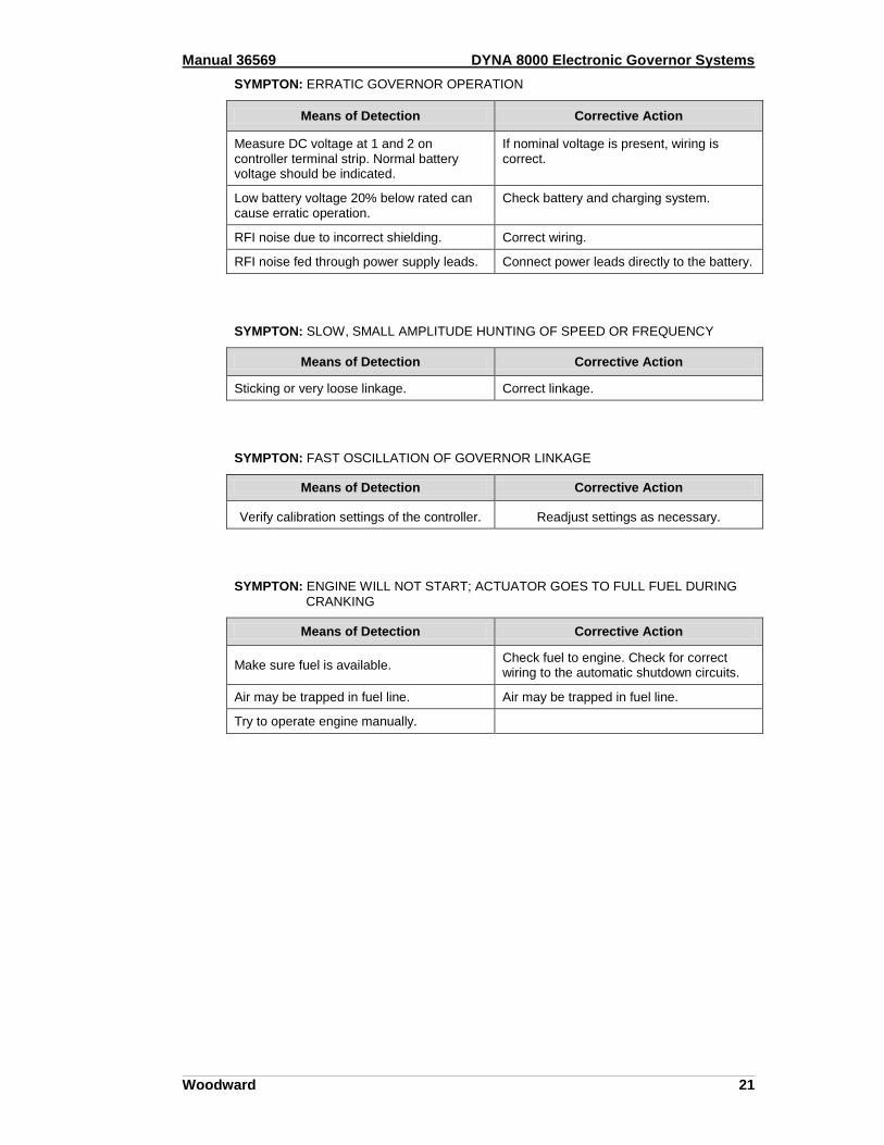
SYMPTON: ERRATIC GOVERNOR OPERATION
Means of Detection Corrective Action
Measure DC voltage at 1 and 2 on controller terminal strip. Normal battery voltage should be indicated.
If nominal voltage is present, wiring is correct.
Low battery voltage 20% below rated can cause erratic operation.
Check battery and charging system.
RFI noise due to incorrect shielding. Correct wiring.
RFI noise fed through power supply leads. Connect power leads directly to the battery.
SYMPTON: SLOW, SMALL AMPLITUDE HUNTING OF SPEED OR FREQUENCY
Means of Detection Corrective Action
Sticking or very loose linkage. Correct linkage.
SYMPTON: FAST OSCILLATION OF GOVERNOR LINKAGE
Means of Detection Corrective Action
Verify calibration settings of the controller. Readjust settings as necessary.
SYMPTON: ENGINE WILL NOT START; ACTUATOR GOES TO FULL FUEL DURING
CRANKING
Means of Detection Corrective Action
Make sure fuel is available. Check fuel to engine. Check for correct wiring to the automatic shutdown circuits.
Air may be trapped in fuel line. Air may be trapped in fuel line.
Try to operate engine manually.

Manual 36569 DYNA 8000 Electronic Governor Systems
Woodward 22
Chapter 6. Service Options
Product Service Options
If you are experiencing problems with the installation, or unsatisfactory performance of a Woodward product, the following options are available:
Consult the troubleshooting guide in the manual.
Contact the manufacturer or packager of your system.
Contact the Woodward Full Service Distributor serving your area.
Contact Woodward technical assistance (see ―How to Contact Woodward‖ later in this chapter) and discuss your problem. In many cases, your problem can be resolved over the phone. If not, you can select which course of action to pursue based on the available services listed in this chapter.
OEM and Packager Support: Many Woodward controls and control devices are installed into the equipment system and programmed by an Original Equipment Manufacturer (OEM) or Equipment Packager at their factory. In some cases, the programming is password-protected by the OEM or packager, and they are the best source for product service and support. Warranty service for Woodward products shipped with an equipment system should also be handled through the OEM or Packager. Please review your equipment system documentation for details. Woodward Business Partner Support: Woodward works with and supports a global network of independent business partners whose mission is to serve the users of Woodward controls, as described here:
A Full Service Distributor has the primary responsibility for sales, service, system integration solutions, technical desk support, and aftermarket marketing of standard Woodward products within a specific geographic area and market segment.
An Authorized Independent Service Facility (AISF) provides authorized service that includes repairs, repair parts, and warranty service on Woodward's behalf. Service (not new unit sales) is an AISF's primary mission.
A Recognized Engine Retrofitter (RER) is an independent company that does retrofits and upgrades on reciprocating gas engines and dual-fuel conversions, and can provide the full line of Woodward systems and components for the retrofits and overhauls, emission compliance upgrades, long term service contracts, emergency repairs, etc.
A Recognized Turbine Retrofitter (RTR) is an independent company that does both steam and gas turbine control retrofits and upgrades globally, and can provide the full line of Woodward systems and components for the retrofits and overhauls, long term service contracts, emergency repairs, etc.
A current list of Woodward Business Partners is available at
www.woodward.com/support.

Manual 36569 DYNA 8000 Electronic Governor Systems
Woodward 23
Woodward Factory Servicing Options The following factory options for servicing Woodward products are available through your local Full-Service Distributor or the OEM or Packager of the equipment system, based on the standard Woodward Product and Service Warranty (5-01-1205) that is in effect at the time the product is originally shipped from Woodward or a service is performed:
Replacement/Exchange (24-hour service)
Flat Rate Repair
Flat Rate Remanufacture Replacement/Exchange: Replacement/Exchange is a premium program designed for the user who is in need of immediate service. It allows you to request and receive a like-new replacement unit in minimum time (usually within 24 hours of the request), providing a suitable unit is available at the time of the request, thereby minimizing costly downtime. This is a flat-rate program and includes the full standard Woodward product warranty (Woodward Product and Service Warranty 5-01-1205). This option allows you to call your Full-Service Distributor in the event of an unexpected outage, or in advance of a scheduled outage, to request a replacement control unit. If the unit is available at the time of the call, it can usually be shipped out within 24 hours. You replace your field control unit with the like-new replacement and return the field unit to the Full-Service Distributor. Charges for the Replacement/Exchange service are based on a flat rate plus shipping expenses. You are invoiced the flat rate replacement/exchange charge plus a core charge at the time the replacement unit is shipped. If the core (field unit) is returned within 60 days, a credit for the core charge will be issued. Flat Rate Repair: Flat Rate Repair is available for the majority of standard products in the field. This program offers you repair service for your products with the advantage of knowing in advance what the cost will be. All repair work carries the standard Woodward service warranty (Woodward Product and Service Warranty 5-01-1205) on replaced parts and labor. Flat Rate Remanufacture: Flat Rate Remanufacture is very similar to the Flat Rate Repair option with the exception that the unit will be returned to you in ―like-new‖ condition and carry with it the full standard Woodward product warranty (Woodward Product and Service Warranty 5-01-1205). This option is applicable to mechanical products only.

Manual 36569 DYNA 8000 Electronic Governor Systems
Woodward 24
Returning Equipment for Repair
If a control (or any part of an electronic control) is to be returned for repair, please contact your Full-Service Distributor in advance to obtain Return Authorization and shipping instructions. When shipping the item(s), attach a tag with the following information:
return number;
name and location where the control is installed;
name and phone number of contact person;
complete Woodward part number(s) and serial number(s);
description of the problem;
instructions describing the desired type of repair. Packing a Control Use the following materials when returning a complete control:
protective caps on any connectors;
antistatic protective bags on all electronic modules;
packing materials that will not damage the surface of the unit;
at least 100 mm (4 inches) of tightly packed, industry-approved packing material;
a packing carton with double walls;
a strong tape around the outside of the carton for increased strength.
To prevent damage to electronic components caused by improper handling, read and observe the precautions in Woodward manual 82715, Guide for Handling and Protection of Electronic Controls, Printed Circuit Boards, and Modules.
Replacement Parts
When ordering replacement parts for controls, include the following information:
the part number(s) (XXXX-XXXX) that is on the enclosure nameplate;
the unit serial number, which is also on the nameplate.

Manual 36569 DYNA 8000 Electronic Governor Systems
Woodward 25
Engineering Services Woodward offers various Engineering Services for our products. For these services, you can contact us by telephone, by email, or through the Woodward website.
Technical Support
Product Training
Field Service Technical Support is available from your equipment system supplier, your local Full-Service Distributor, or from many of Woodward’s worldwide locations, depending upon the product and application. This service can assist you with technical questions or problem solving during the normal business hours of the Woodward location you contact. Emergency assistance is also available during non-business hours by phoning Woodward and stating the urgency of your problem. Product Training is available as standard classes at many of our worldwide locations. We also offer customized classes, which can be tailored to your needs and can be held at one of our locations or at your site. This training, conducted by experienced personnel, will assure that you will be able to maintain system reliability and availability. Field Service engineering on-site support is available, depending on the product and location, from many of our worldwide locations or from one of our Full-Service Distributors. The field engineers are experienced both on Woodward products as well as on much of the non-Woodward equipment with which our products interface. For information on these services, please contact us via telephone, email us, or use our
website and reference www.woodward.com/support, and then Customer Support.
How to Contact Woodward For assistance, call one of the following Woodward facilities to obtain the address and phone number of the facility nearest your location where you will be able to get information and service.
Electrical Power Systems
FACILITY PHONE NUMBER
Brazil ------------- +55 (19) 3708 4800
China ------------ +86 (512) 6762 6727
Germany:
Kempen --- +49 (0) 21 52 14 51
Stuttgart ----- +49 (711) 78954-0
India --------------- +91 (129) 4097100
Japan -------------- +81 (43) 213-2191
Korea--------------- +82 (51) 636-7080
Poland -------------- +48 12 295 13 00
United States----- +1 (970) 482-5811
Engine Systems
FACILITY PHONE NUMBER
Brazil ------------- +55 (19) 3708 4800
China ------------ +86 (512) 6762 6727
Germany:
Stuttgart ----- +49 (711) 78954-0
India --------------- +91 (129) 4097100
Japan -------------- +81 (43) 213-2191
Korea--------------- +82 (51) 636-7080
The Netherlands - +31 (23) 5661111
United States----- +1 (970) 482-5811
Turbine Systems
FACILITY PHONE NUMBER
Brazil ------------- +55 (19) 3708 4800
China ------------ +86 (512) 6762 6727
India --------------- +91 (129) 4097100
Japan -------------- +81 (43) 213-2191
Korea--------------- +82 (51) 636-7080
Poland -------------- +48 12 295 13 00
The Netherlands - +31 (23) 5661111
United States----- +1 (970) 482-5811
You can also contact the Woodward Customer Service Department or consult our
worldwide directory on Woodward’s website (www.woodward.com/support) for the
name of your nearest Woodward distributor or service facility. For the most current product support and contact information, please refer to the latest
version of publication 51337 at www.woodward.com/publications.
Manual 36569 DYNA 8000 Electronic Governor Systems
Woodward 26
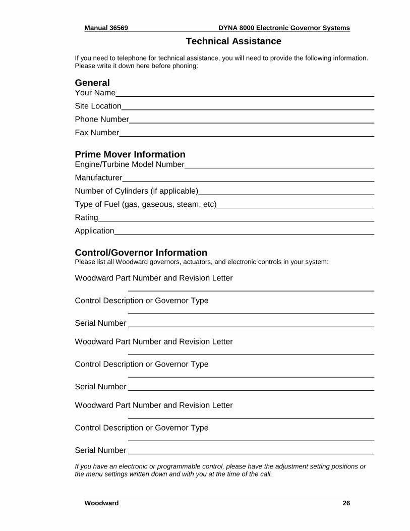
Technical Assistance If you need to telephone for technical assistance, you will need to provide the following information. Please write it down here before phoning:
General Your Name
Site Location
Phone Number
Fax Number
Prime Mover Information Engine/Turbine Model Number
Manufacturer
Number of Cylinders (if applicable)
Type of Fuel (gas, gaseous, steam, etc)
Rating
Application
Control/Governor Information Please list all Woodward governors, actuators, and electronic controls in your system:
Woodward Part Number and Revision Letter
Control Description or Governor Type
Serial Number Woodward Part Number and Revision Letter
Control Description or Governor Type
Serial Number Woodward Part Number and Revision Letter
Control Description or Governor Type
Serial Number If you have an electronic or programmable control, please have the adjustment setting positions or the menu settings written down and with you at the time of the call.

Manual 36569 DYNA 8000 Electronic Governor Systems
Woodward 27

We appreciate your comments about the content of our publications.
Send comments to: [email protected]
Please reference publication 36569.
PO Box 1519, Fort Collins CO 80522-1519, USA 1000 East Drake Road, Fort Collins CO 80525, USA
Phone +1 (970) 482-5811 Fax +1 (970) 498-3058
Email and Website—www.woodward.com
Woodward has company-owned plants, subsidiaries, and branches, as well as authorized distributors and other authorized
service and sales facilities throughout the world.
Complete address / phone / fax / email information for all locations is available on our website.
2010/9/Skokie