
DX5e Quick Start Guide -...
26
The Spektrum trademark is used with permission of Bachmann Industries, Inc. DX5e Quick Start Guide 1. Install Receiver Example of AR500 installed in E-flite ® Apprentice Though in general it is non-critical, optimum installation of the antenna is to orient the tip of the long antenna perpendicular to the short antenna. The tip on the long antenna should be a least 2 inches from the short antenna. Example of AR500 installed in Hangar 9 ® Pulse ™ XT 60 2. Install AA Size Heavy-Duty or Alkaline Batteries Note: Observe polarity when installing batteries. 3. Bind Receiver A. Plug the bind plug into the receiver’s BATT/BIND port. In systems utiliz- ing a separate battery pack and 3-wire switch, plug the bind plug into the charge jack. B. Power up the receiver. The LED on the receiver will be flashing. C. Move the sticks and switches on the transmitter to the desired failsafe positions (low throttle and neutral control positions). D. Pull and hold the Trainer Switch on the transmitter while turning the transmitter on. Release the trainer switch once the LEDs on the front of the transmitter flash. E. The LED on the receiver will go solid amber and the system will connect after several seconds. F. Remove the bind plug from the charge jack or bind port. Typical Electric - Rx uses the ESC for power. Typical Glow/Gas - uses receiver pack and 3-wire switch. 4. Test System Battery Voltage Lack of power to the receiver and servos is a leading cause of failure. If you are using a receiver pack, ensure that it is properly charged and check the voltage under load (HAN172). Do not fly if voltage is below 4.8V for a 4-cell pack. In systems using a BEC, ensure that you are not driving more than the man- ufacturer’s recommended number of servos for your BEC/Speed control. If at anytime, the voltage should fall below the receiver’s operating threshold, an interruption in the link may occur followed by a blinking light on the receiver. A more accurate way to test a questionable setup is to measure the voltage per the instructions on page 17. Note: If the receiver power is cycled without cycling the transmitter, a blink- ing light will also occur. In this case, this does not indicate a problem. Cycle the Tx power, and then the Rx, to reset the light. 5. Control Surface Check Turn on the transmitter followed by the receiver and check that the direction of each channel is correct. Use the servo reversing switches on the front of the transmitter to change the direction if necessary. 6. Re-Bind the System After you’ve set up your model, it’s important to re-bind the system so the true low throttle position is stored. If the signal is lost, the throttle servo will drive to a low throttle safe position. 7. Range Check How to Range Check 1. With the model resting on the ground, stand 30 paces (approximately 90 feet/28 meters) away from the model. 2. Face the model with the transmitter in your normal flying position and pull and hold the Trainer Switch while toggling the HI/LO Rate Switch four times. The LEDs will flash and the alarm will sound indicating the system is in range check mode. 3. You should have total control of the model with the Trainer Switch pulled at 30 paces (90 feet/28 meters). 4. If control issues exist, call the Horizon Support Team at 1-877-504-0233 or go to horizonhobby.com to find a local Spektrum distributor in your country of service. Revised 12/08 13639.1 Pull and hold the Trainer Switch 30 paces (90 feet/28 meters) Elevator Stick UP Elevator Stick DOWN Aileron Stick LEFT Aileron Stick RIGHT Rudder Stick LEFT Rudder Stick RIGHT Leaders in Spread Spectrum Technology Tape antenna in place. Do not allow tip to touch metal. A. Insert Bind Plug Receiver pack and 3-wire switch B. Apply power to system A, B. Insert bind plug into charge jack, apply power C, D. Pull trainer switch, turn power on Note: Continuing to hold the trainer switch during the binding process will prevent preset failsafe positions from being learned by the receiver.
Transcript of DX5e Quick Start Guide -...

The Spektrum trademark is used with permission of Bachmann Industries, Inc.
DX5e Quick Start Guide 1. Install Receiver
Example of AR500 installed in E-flite® Apprentice Though in general it is non-critical, optimum installation of the antenna is to orient the tip of the long antenna perpendicular to the short antenna. The tip on the long antenna should be a least 2 inches from the short antenna.
Example of AR500 installed in Hangar 9® Pulse™ XT 60
2. Install AA Size Heavy-Duty or Alkaline Batteries Note: Observe polarity when installing batteries.
3. Bind Receiver A. Plug the bind plug into the receiver’s BATT/BIND port. In systems utiliz-
ing a separate battery pack and 3-wire switch, plug the bind plug into the charge jack.
B. Power up the receiver. The LED on the receiver will be flashing. C. Move the sticks and switches on the transmitter to the desired failsafe
positions (low throttle and neutral control positions). D. Pull and hold the Trainer Switch on the transmitter while turning the
transmitter on. Release the trainer switch once the LEDs on the front of the transmitter flash.
E. The LED on the receiver will go solid amber and the system will connect after several seconds.
F. Remove the bind plug from the charge jack or bind port.
Typical Electric - Rx uses the ESC for power. Typical Glow/Gas - uses receiver pack and 3-wire switch.
4. Test System Battery Voltage Lack of power to the receiver and servos is a leading cause of failure. If you
are using a receiver pack, ensure that it is properly charged and check the voltage under load (HAN172). Do not fly if voltage is below 4.8V for a 4-cell pack. In systems using a BEC, ensure that you are not driving more than the man-ufacturer’s recommended number of servos for your BEC/Speed control. If at anytime, the voltage should fall below the receiver’s operating threshold, an interruption in the link may occur followed by a blinking light on the receiver. A more accurate way to test a questionable setup is to measure the voltage per the instructions on page 17.
Note: If the receiver power is cycled without cycling the transmitter, a blink-
ing light will also occur. In this case, this does not indicate a problem. Cycle the Tx power, and then the Rx, to reset the light.
5. Control Surface Check Turn on the transmitter followed by the receiver and check that the direction of each channel is correct. Use the servo reversing switches on the front of the transmitter to change the direction if necessary.
6. Re-Bind the System After you’ve set up your model, it’s important to re-bind the system so the true low
throttle position is stored. If the signal is lost, the throttle servo will drive to a low throttle safe position.
7. Range Check
How to Range Check1. With the model resting on the ground, stand 30 paces
(approximately 90 feet/28 meters) away from the model.2. Face the model with the transmitter in your normal flying position
and pull and hold the Trainer Switch while toggling the HI/LO Rate Switch four times. The LEDs will flash and the alarm will sound indicating the system is in range check mode.3. You should have total control of the model with the Trainer Switch pulled
at 30 paces (90 feet/28 meters). 4. If control issues exist, call the Horizon Support Team at 1-877-504-0233 or go to horizonhobby.com to find a local Spektrum distributor in your country of service.
Revised 12/08 13639.1
Pull and hold the Trainer Switch
30 paces (90 feet/28 meters)
Elevator Stick UP Elevator Stick DOWN
Aileron Stick LEFT Aileron Stick RIGHT
Rudder Stick LEFT Rudder Stick RIGHT
Leaders in Spread Spectrum Technology
Tape antenna in place. Do not allow tip to touch metal.
A. Insert Bind Plug Receiver pack and 3-wire switch
B. Apply power to system A, B. Insert bind plug into charge jack, apply power
C, D. Pull trainer switch, turn power on
Note: Continuing to hold the trainer switch during the binding process will prevent preset failsafe positions from being learned by the receiver.

5-Channel Full Range DSM2™ 2.4GHz Radio System
Leaders in Spread Spectrum Technology

2 SPEKTRUM DX5e • RADIO USER’S GUIDE 3SPEKTRUM DX5e • RADIO USER’S GUIDE
TRAnSMITTER COnTROl IDEnTIfICATIOn
On/Off Switch
Reversing Switches
Trainer Port
Channel 5 Switch
Throttle andAileron Stick
Rudder andElevator Stick
Elevator Trim
Throttle Trim
Aileron Trim
RudderTrim
HI/LO Rate Switch
Charge Jack
Trainer Switch
Mix Switch
Antenna
Mode 1
On/Off Switch
Reversing Switches
Trainer Port
Channel 5 Switch
Throttle andRudder Stick Aileron and
Elevator Stick
Rudder TrimElevator Trim
Throttle Trim
Aileron Trim
HI/LO Rate Switch
Charge Jack
Trainer Switch
Mix Switch
Antenna
Mode 2
TAblE Of COnTEnTSSpektrum’s DX5e 5-channel DSM2
Full Range System ..................................... 2DSM2 DuaLink® Technology ............................ 4Receiver Compatibility ..................................... 4Installing the Transmitter Batteries................... 5Charging Batteries ............................................ 5Digital Trims ..................................................... 6Low Battery Alarm ........................................... 6Trainer .............................................................. 7Receiver Installation ......................................... 7Binding ............................................................. 8How to Range Test the DX5e ............................ 9AR500 Failsafe ............................................... 10HOW AR500 FAILSAFE WORKS ..................... 10Servo Reversing ............................................. 10Hi/Lo Rate ...................................................... 10Elevon/ Delta mixing ...................................... 11Receiver Power System Requirements .......... 11Tips on Using 2.4GHz Systems ...................... 12General Information ....................................... 13Warranty Information ..................................... 15Instructions for Disposal of WEEE by
Users in the European Union .................... 17Optional Accessories ...................................... 18
SPEKTRUM’S DX5E 5-ChAnnEl DSM2 fUll RAnGE SySTEMSpektrum’s DX5e 5-channel system incorporates 2.4GHz DSM2 technology offering full beyond-the-limits-of-sight range and is ideal for sport-sized electric, gas and glow-powered 5-channel or fewer airplanes. No longer will you have to wait for a frequency pin or be concerned that someone may inadvertently turn on to your same frequency. With Spektrum DSM2 technology, when you’re ready to fly simply turn on, and go flying!

4 SPEKTRUM DX5e • RADIO USER’S GUIDE 5SPEKTRUM DX5e • RADIO USER’S GUIDE
DSM2 DUAlInK® TEChnOlOGyYour DX5e transmits on the 2.4GHz band and utilizes DSM2™ second-generation Digital Spread Spectrum Modulation, giving beyond-visual range in all types and sizes of aircraft. Unlike conventional narrow band systems, Spektrum’s 2.4GHz digital DuaLink technology is virtually immune to internal and external radio interference.
Included with your DX5e is an AR500 5-channel full-range sport receiver. The DX5e transmitter simultaneously transmits on two frequencies and the AR500 receives both frequencies, creating dual RF paths. This dual path redundancy creates a bulletproof RF link. The AR500 features two aileron outputs making it convenient when using airplanes with two aileron servos.
RECEIvER COMPATIbIlITyThe DX5e is compatible with all current Spektrum™ and JR® brands of DSM® aircraft receivers. However, when using the DX5e with one of the Spektrum park flyer receivers, like the AR6000, AR6100, AR6100E, etc., it is imperative that these receivers be limited to flying Parkflyer-type aircraft.
PARK flyER RECEIvERS
•AR6000 •AR6100
•AR6100E •AR6300
fUll RAnGE DSM2 AIRCRAfT RECEIvERS
•AR6200 •AR7000 •AR9000
•AR7100 •AR7100R •AR9100
InSTAllInG ThE TRAnSMITTER bATTERIESThe DX5e requires 4 heavy duty or alkaline AA batteries.
bATTERy InSTAllATIOn
Remove the battery door and install 4 AA batteries. Make sure the polarity of each corresponds with the diagram in the battery holder. Replace the battery door.
note: Optional NiCd or NiMH 1.2-volt AA rechargeable batteries can also be used. A charge jack is located on the right side of the transmitter for convenient recharging. Spektrum offers optional replacement NiMH rechargeablebatteries,partnumberSPM9525.
ChARGInG bATTERIESIf using rechargeable batteries (optional), it is imperative that you fully charge the transmitter prior to each flying session. To do so, using the optional wall charger, leave the charger and batteries connected overnight (16 hours).
Theoptionalcharger(SPM9526)isdesignedtorechargeyour batteries at a rate of 150mA for the transmitter and 150mA for the receiver battery pack. Do not use this charger for equipment other than Spektrum transmitters that use 4-cell battery packs. The charging plug polarity may not be the same and equipment damage can result. During the charging operation, the charger’s temperature is slightly elevated. This is normal.
Charger Pigtail for Transmitter
Spektrum Transmitter Charge Jack Polarity
BLACK TO POSITIVE
BLACK W/WHITE STRIPE TO NEGATIVE
- +
A charging jack is located on the right side of the transmitter. If rechargeable batteries are used they can be conveniently charged without removing them from the transmitter using the charge jack.

6 SPEKTRUM DX5e • RADIO USER’S GUIDE 7SPEKTRUM DX5e • RADIO USER’S GUIDE
IMPORTAnT: All Spektrum charge jacks are center-pin negative. This is the opposite of many chargers. Before using a charger make sure the connector is center-pin negative. This can be done using a voltmeter. Also unlike conventional radio systems that use 8 cells to power the transmitter, the DX5e uses 4 cells. This is due to the electronics being more efficient. When charging, be sure to use a charger designed for a 4-cell 4.8-volt battery pack when charging the transmitter.
TRAnSMITTER POlARITyThe center pin on all Spektrum transmitters is negative. Therefore, the center pin on all Spektrum chargers is negative, not positive. This is different from many other manufacturers’ chargers and radio systems. Beware of improper connections based on “color coded” wire leads, as they may not apply in this instance. You must make sure that the center pin of your Spektrum transmitter is always connected to the negative voltage of your charger for correct polarity hookup.
DIGITAl TRIMSThe DX5e features digital trims. Each time a trimmer is moved the servo output will change one step. If the trimmer is held, the output will scroll in that direction until the trimmer is released or the output reaches its end.
Rudder Trim
Elevator TrimThrottle Trim
Aileron Trim
Mode 2
Rudder Trim
Throttle TrimElevator Trim
Aileron Trim
Mode 1
lOw bATTERy AlARMWhenthebatteryvoltagedropsbelow4.7volts,analarmwill sound and the voltage LEDs will flash.
TRAInERThe DX5e offers a trainer function that allows the transmitter to operate as a master or slave. The trainer switch is located on the back left of the transmitter. When using the trainer function, plug the trainer cord (SPM6805) into the trainer port in both the master (controlling) and the slave (training) transmitters. The master transmitter must have the power turned on and the slave transmitter must have the power turned off.
note: The DX5e trainer system is compatible with all JR and Spektrum transmitters.
MASTERThe DX5e transmitter can be used as a master but the slave transmitter must have the same programming (i.e. reverse switch positions) as the master.
SlAvEWhen using the DX5e transmitter as a slave with another DX5e, it’s necessary to match all the reverse switch positions.
RECEIvER InSTAllATIOnThe AR500 incorporates dual receiver antennas, offering the security of dual path RF redundancy. By locating these antennas in slightly different locations in the aircraft, each antenna is exposed to its own RF environment, greatly improving path diversity (the ability for the receiver to see the signal in all conditions). The receiver features two aileron outputs making it convenient when installing the receiver in airplanes that have two aileron servos.
RECEIvER InSTAllATIOn
Install the receiver using the same method you would use to install a conventional receiver in your aircraft. Typically, wrap the receiver in protective foam and fasten it in place using rubber bands or hook and loop straps. Alternately, in electric models, it’s acceptable to use thick double-sided foam tape to fasten the main receiver in place.
Mount the antennas such that the tip of the feeder (long) antennaisperpendicular(90degrees)totheshortantennaand the antennas are at least 2 inches apart. Essentially, each antenna sees a different RF environment and this is key to maintaining a solid RF link.

8 SPEKTRUM DX5e • RADIO USER’S GUIDE 9SPEKTRUM DX5e • RADIO USER’S GUIDE
bInDInGThe AR500 receiver must be bound to the transmitter before it will operate. Binding is the process of teaching the receiver the specific code of the transmitter so it will only connect to that specific transmitter.
note: RTF and Radio Systems are pre-bound at the factory. Rebinding is necessary if any settings are changed to ensure proper failsafe settings are achieved.
1. To bind an AR500 to a DSM2 transmitter, insert the BATT/BIND port in the charge plug receptacle.
note: To bind an aircraft with an electronic speed controller that powers the receiver through the throttle channel (ESC/BEC), insert the bind plug into the BATT/BIND port in the receiver and the throttle lead into the throttle port. Proceed to Step #2.
2. Power the receiver by plugging in a receiver battery in any port on the receiver. Note that the LED on the receiver should be flashing, indicating that the receiver is in bind mode and ready to be bound to the transmitter.
Shown above using a separate receiver pack
note: When binding using a switch harness and separate receiver pack, a three-wire switch harness mustbeusedsuchasSPM9530.(Notshown)YoumayneedtopurchasetheMale/FemalebindplugSPM6803in addition to the switch harness.
Shown above using an ESC/bEC and a flight pack
3. Movethesticksandswitchesonthetransmittertothe desired AR500 failsafe positions (low throttle and neutral control positions).
4. Pull and hold the trainer switch on the top of the transmitter while turning on the power switch. Release the trainer switch once the LEDs on the front of the transmitter flash, and a series of tones are heard. Within a few seconds the system should connect. Once connected the LED on the receiver will go solid indicating the system is connected.
note: Continuing to hold the trainer switch during the binding process will prevent preset failsafe positions from being learned by the receiver.
5. Remove the bind plug from the BATT/BIND port on the receiver before you power off the receiver and store it in a convenient place.
6. After you’ve set up your model, it’s important to rebind the system so the true low throttle and neutral control surface positions are programmed.
hOw TO RAnGE TEST ThE DX5EBefore each flying session, and especially with a new model, it is important to perform a range check. The DX5e incorporates a range testing system which, when placed in the RANGE CHECK mode with the trainer switch activated and held, reduces the output power, allowing a range check.
RAnGE TESTInG ThE DX5E1. Withthemodelrestrainedontheground,stand30
paces(approx.90feet/28meters)awayfromthemodel.
note: Prior to performing the range check ensure the correct failsafe stick positions are established.
2. Face the model with the transmitter in your normal flying position. Pull and hold the trainer switch while toggling the HI/LO Rate Switch four times. The LEDs will flash and the alarm will sound indicating the system is in range check mode.
note: The trainer switch must be held the entire time during the range check process; releasing the trainer switch will exit the range check mode.
HI/LO Rate Switch
Trainer Switch
3. Youshouldhavetotalcontrolofthemodelwiththetrainerswitchpulledat30paces(90feet/28meters).
4. If control issues exist, call the Horizon Product SupportTeamat18775040233orgotohorizonhobby.com to find a local Spektrum distributor for service in your country.
30 paces (90 feet/28 meters)

10 SPEKTRUM DX5e • RADIO USER’S GUIDE 11SPEKTRUM DX5e • RADIO USER’S GUIDE
AR500 fAIlSAfE• Preventsunintentionalelectricmotorresponseon
start-up.• Eliminatesthepossibilityofover-drivingservoson
start-up.• Establisheslow-throttlefailsafeiftheRFsignalislost.• TheAR500removesservooutputpulsestoallchannels
except the throttle channel during failsafe.• TheAR500throttlefailsafepositionisstoredviathe
throttle stick position on the transmitter.
hOw AR500 fAIlSAfE wORKS
RECEIvER POwER Only
• Inelectricaircraft,whenthereceiveronlyisturnedon(no transmitter signal is present), the throttle channel has no output, to avoid operating or arming the electronic speed control.
• Inglow-poweredmodels,thethrottleservoreceivesnoinput so it remains in its current position.
note: Some analog servos will coast slightly even though there is no signal present. This is normal.
• Allotherchannelswillmovetothepositionsset during binding
AfTER COnnECTIOn
• Whenthetransmitteristurnedon,andafterthereceiverconnects to the transmitter, normal control of all channels occurs.
• Afterthesystemmakesaconnection,iflossofsignaloccurs, the AR500 failsafe drives the throttle servo only to its preset failsafe position (low throttle) that was set during binding.
• Allotherchannelsreceivenooutputpulses/commands,and are not active during failsafe.
SERvO REvERSInGThe DX5e features servo reversing on channels 1-4. The switches are located at the lower front of the transmitter and are used to select the direction of each channel. Use a small screwdriver to change the switch position to normal or reverse.
hI/lO RATEThe DX5e offers a high/low rate function on aileron, elevator and rudder. When the HI/LO rate switch is in the upper position or “HI” position, 100% travel is achieved on the aileron, elevator and rudder channels. When the switchisinthelowerpositionareducedtravelof70%isachieved on the aileron, elevator and rudder channels. This is useful allowing the aircraft to have a high control rate (switch in the “HI” position) for aggressive maneuvers and a low control rate (switch in “LO” position) for smooth, precise maneuvers.
• High100%rateonaileron,elevatorandrudder• Low70%rateonaileron,elevatorandrudder
ElEvOn/ DElTA MIXInGThe DX5e offers an Elevon mix. Elevon (also called delta wing) mixing combines the function of ailerons with the function of the elevator to allow precise control of both roll and pitch for delta wing aircraft. To activate the Elevon mix, move the mix switch to the on (up) position.
AILE Servo Port(Left Elevon)
ELEV Servo Port(Right Elevon)
Elevon Wing Type Connection
• ELEVservoport(rightaileron)• AILEservoport(leftaileron)
note: If proper servo direction cannot be achieved with the servo reversing switches, swap the servo input leadsfromAILEtoELEVorviceversa.
RECEIvER POwER SySTEM REqUIREMEnTSWith all radio installations, it is vital the onboard power system provides adequate power without interruption to the receiver even when the system is fully loaded (servos at maximum flight loads). This becomes especially critical with giant-scale models that utilize multiple high-torque/ high-current servos. Inadequate power systems that are unable to provide the necessary minimum voltage to the receiver during flight loads have become the number-one cause of in-flight failures. Some of the power system components that affect the ability to properly deliver adequate power include: the selected receiver battery pack (number of cells, capacity, cell type, state of charge), switch harness, battery leads, regulator (if used) and, unless it’s a regulator, power bus (if used).
While a Spektrum receiver’s minimum operational voltage is 3.5volts,itishighlyrecommendedthesystem be tested per the guidelines below to a minimum acceptable voltage of 4.8 volts during ground testing. This will provide head room to compensate for battery discharging or if the actual flight loads are greater than the ground test loads.
RECOMMEnDED POwER SySTEM GUIDElInES
1. When setting up large or complex aircraft with multiple high-torque servos, it’s highly recommended that a currentandvoltmeter(Hangar9HAN172)beused.Plugthe voltmeter in an open channel port in the receiver and, with the system on, load the control surfaces (apply pressure with your hand) while monitoring the voltage at the receiver. The voltage should remain above 4.8 volts even when all servos are heavily loaded.
2. With the current meter in line with the receiver battery lead, load the control surfaces (apply pressure with your hand) while monitoring the current. The maximum continuous recommended current for a single heavy-duty servo/battery lead is three amps while short-duration current spikes of up to five amps are acceptable. Consequently, if your system draws more than three amps continuous or five amps for short durations, a single battery pack with a single switch harness plugged into the receiver for power will be inadequate. It will be necessary to use multiple packs with multiple switches and multiple leads plugged into the receiver.

12 SPEKTRUM DX5e • RADIO USER’S GUIDE 13SPEKTRUM DX5e • RADIO USER’S GUIDE
3. Ifusingaregulator,it’simportanttheabovetestsaredone for an extended period of 5 minutes. When current passes through a regulator, heat is generated. This heat causes the regulator to increase resistance, which in turn causes even more heat to build up (thermal runaway). While a regulator may provide adequate power for a short duration, it’s important to test its ability over time as the regulator may not be able to maintain voltage at significant power levels.
4. For really large aircraft or complex models (for example 35%andlargerorjets),multiplebatterypackswithmultiple switch harnesses are necessary or in many cases one of the commercially available power boxes/ busses is recommended. No matter what power systems you choose, always carry out test #1 above making sure that the receiver is constantly provided with 4.8 volts or more under all conditions.
5. The latest generation of Nickel-Metal Hydride batteries incorporates a new chemistry mandated to be more environmentally friendly. These batteries, when charged with peak detection fast chargers, have a tendency to false peak (not fully charge) repeatedly. These include all brands of NiMH batteries. If using NiMH packs be especially cautious when charging making absolutely sure that the battery is fully charged. It is recommended to use a charger that can display total charge capacity. Note the number of mAh put into a discharged pack to verify it has been charged to full capacity.
TIPS On USInG 2.4Ghz SySTEMSYour DSM2 equipped 2.4GHz system is intuitive to operate, functioning nearly identically to FM systems. Following are a few common questions from customers:
1. Q: Which do I turn on first, the transmitter or the receiver?
A: It doesn’t matter, although it is suggested to turn the transmitter on first. If the receiver is turned on first, the throttle channel doesn’t put out a pulse position at this time, preventing the arming of electronic speed controllers, or in the case of an engine powered aircraft, the throttle servo remains in its current position. When the transmitter is then turned on the transmitter scans the 2.4GHz band and acquires two open channels. Then the receiver that was previously bound to the transmitter scans the band and finds the GUID (Globally Unique Identifier code) stored during binding. The system then connects and operates normally. If the transmitter is turned on first, the transmitter scans the 2.4GHz band and acquires two open channels. When the receiver is turned on, the receiver scans the 2.4GHz band looking for the previously stored GUID. When it locates the specific GUID code and confirms uncorrupted repeatable packet information, the system connects and normal operation takes place. Typically this takes 2 to 6 seconds.
2. Q: Sometimes the system takes longer to connect and sometimes it doesn’t connect at all. Why?
A In order for the system to connect (after the receiver is bound), the receiver must receive a large number of continuous (one after the other) uninterrupted perfect packets from the transmitter. This process is purposely critical of the environment ensuring that it’s safe to fly when the system does connect. If the transmitter is too close to the receiver (less that 4 feet) or if the transmitter is located near metal objects (metal transmitter case, the bed of a truck, the top of a metal work bench, etc.) connection will take longer. In some cases connection will not occur as the system is receiving reflected 2.4GHz energy from itself and is interpreting this as unfriendly noise. Moving the system away from metal objects or moving the transmitter away from the receiver and powering the system up again will cause a connection to occur. This only happens during the initial connection. Once connected the system is locked, and should a loss of signal occur (failsafe), the system connects immediately (4ms) when signal is regained.
3. Q:I’veheardthattheDSMsystemislesstolerantoflowvoltage. Is this correct?
A: All DSM receivers have an operational voltage range of 3.5to9volts.Withmostsystemsthisisnotaproblemasinfactmostservosceasetooperateataround3.8volts. When using multiple high-current draw servos with a single or inadequate battery/ power source, heavy momentary loads can cause the voltage to dip below this3.5-voltthresholdcausingtheentiresystem(servosand receiver) to brown out. When the voltage drops belowthelowvoltagethreshold(3.5volts),theDSMreceiver must reboot (go through the start up process of scanning the band and finding the transmitter) and this can take several seconds.
4. Q: Sometimes my receiver loses its bind and won’t connect, requiring rebinding. What happens if the bind is lost in flight?
A: The receiver will never lose its bind unless it’s instructed to. It’s important to understand that during the binding process the receiver not only learns the GUID (code) of the transmitter but the transmitter learns and stores the type of receiver that it’s bound to. If the trainer switch is pulled on the transmitter at any time and the transmitter is turned on, the transmitter looks for the binding protocol signal from a receiver. If no signal is present, the transmitter no longer has the correct information to connect to a specific receiver and in essence the transmitter has been “unbound” from the receiver. We’ve had several customers using transmitter stands or trays that unknowingly depress the bind button. The system is then turned on, losing the necessary information to allow the connection to take place. We’ve also had customers that didn’t fully understand the range test process and pull the trainer switch before turning on the transmitter, also causing the system to “lose its bind.” If the system fails to connect, one of the following has occurred:
• Thetransmitterisnearconductivematerial(transmittercase, truck bed, etc.) and the reflected 2.4GHz energy is preventing the system from connecting. (See #2 above)
• Thetrainerswitchwaspulledandtheradiowaspreviously turned on knowingly (or unknowingly), causing the transmitter to no longer recognize the receiver.
GEnERAl InfORMATIOn
FCC InformationThis device complies with part 15 of the FCC rules. Operation is subject to the following two conditions: (1) This device may not cause harmful interference, and (2) this device must accept any interference received, including interference that may cause undesired operation.
Caution: Changes or modifications not expressly approved by the party responsible for compliance could void the user’s authority to operate the equipment.
This product contains a radio transmitter with wireless technology which has been tested and found to be compliant with the applicable regulations governing a radio transmitter inthe2.400GHzto2.4835GHzfrequencyrange.
Servo Precautions• Donotlubricateservogearsormotors.• Donotoverloadretractservosduringretractedor
extended conditions. Make sure they are able to travel their full deflection. Overloading or stalling a servo can cause excessive current drain.
• Makesureallservosmovefreelythroughtheir rotations and no linkages hang up or bind. A binding control linkage can cause a servo to draw excessive current. A stalled servo can drain a battery pack in a matter of minutes.
• Correctanycontrolsurface“buzz”or“flutter”assoonas it is noticed in flight, as this condition can destroy the feedback potentiometer in the servo. It may be extremely dangerous to ignore such “buzz” or “flutter.”
• Usethesuppliedrubbergrommetsandbrassservoeyelets when mounting your servos. Do not over-tighten the servo mounting screws, as this negates the dampening effect of the rubber grommets.
• Ensuretheservohornissecurelyfastenedtotheservo.Use only the servo arm screws provided; the size is different from other manufacturers.
• Discontinuetouseservoarmswhentheybecome“yellowed” or discolored. Such servo arms may be brittle and can snap at any time, possibly causing the aircraft to crash.
• Checkallrelatedmountingscrewsandlinkagesfrequently. Aircraft often vibrate, causing linkages and screws to loosen.

14 SPEKTRUM DX5e • RADIO USER’S GUIDE 15SPEKTRUM DX5e • RADIO USER’S GUIDE
General NotesRadio controlled models are a great source of pleasure. Unfortunately, they can also pose a potential hazard if not operated and maintained properly.
It is imperative to install your radio control system correctly. Additionally, your level of piloting competency must be high enough to ensure that you are able to control your aircraft under all conditions. If you are a newcomer to radio controlled flying, please seek help from an experienced pilot or your local hobby store.
Safety Do’s and Don’ts for Pilots• Ensurethatyourbatterieshavebeenproperlycharged
prior to your initial flight.• Keeptrackofthetimethesystemisturnedonsoyou
will know how long you can safely operate your system.• Performagroundrangecheckpriortotheinitialflight
of the day. See the “Daily Flight Checks Section” for information.
• Checkallcontrolsurfacespriortoeachtakeoff.• Donotflyyourmodelnearspectators,parkingareasor
any other area that could result in injury to people or damage of property.
• Donotflyduringadverseweatherconditions.Poorvisibility can cause disorientation and loss of control of your aircraft. Strong winds can cause similar problems.
• Donotpointthetransmitterantennadirectlytowardthemodel. The radiation pattern from the tip of the antenna is inherently low.
• Donottakechances.Ifatanytimeduringflightyouobserve any erratic or abnormal operation, land immediately and do not resume flight until the cause of the problem has been ascertained and corrected. Safety can never be taken lightly.
Federal Aviation Administration
PurposeThis advisory outlines safety standards for operations of model aircraft. We encourage voluntary compliance with these standards.
BackgroundAttention has been drawn to the increase in model aircraft operation. There is a need for added caution when operating free flight and radio controlled craft in order to avoid creating a noise nuisance or a potential hazard to full-scale aircraft and persons and/or property on the surface.
Operating StandardsModelers generally are concerned with safety and exercise good judgment when flying model aircraft. However, in the interest of safer skies, we encourage operators of radio controlled and free flight models to comply with the following standards:
a. Exercise vigilance in locating full-scale aircraft (get help if possible) so as not to create a collision hazard.
b. Select an operating site at sufficient distance from populated areas so you do not create a noise problem or a potential hazard.
c. Do not fly higher than 400 feet above the surface.d. Always operate more than three miles from the
boundary of an airport unless you are given permission to be closer by the appropriate air traffic control facility in the case of an airport for which a control zone has been designated or by the airport manager in the case of other airports.
e. Do not hesitate to ask for assistance in complying with these guidelines at the airport traffic control tower or air route traffic control center nearest the site of your proposed operation.
Information Provided ByDirector, Air Traffic Service Federal Aviation Administration, Washington, D.C.
Daily Flight Checks1. Check the battery voltage on both the transmitter and
thereceiverbatterypacks.Donotflybelow4.7Vonthetransmitterorbelow4.7Vonthereceiver.Todosocancrash your aircraft.
note: When you check these batteries, ensure that you have the polarities correct on your expanded scale voltmeter.
2. Check all hardware (linkages, screws, nuts, and bolts) prior to each day’s flight. Be sure that binding does not occur and that all parts are properly secured.
3. Ensurethatallsurfacesaremovinginthepropermanner.
4. Perform a ground range check before each day’s flying session.
5. Prior to starting your aircraft, turn off your transmitter, then turn it back on. Do this each time you start your aircraft. If any critical switches are on without your knowledge, the transmitter alarm will warn you at this time.
6. Check that all trim levers are in the proper location.7. Allservopigtailsandswitchharnessplugsshould
be secured in the receiver. Make sure that the switch harness moves freely in both directions.
wARRAnTy InfORMATIOn
Warranty PeriodHorizon Hobby, Inc., (Horizon) warranties that the Products purchased (the “Product”) will be free from defects in materials and workmanship at the date of purchase by the Purchaser.
Limited Warranty(a) This warranty is limited to the original Purchaser (“Purchaser”) and is not transferable. REPAIR OR REPLACEMENTASPROVIDEDUNDERTHISWARRANTYISTHEEXCLUSIVEREMEDYOFTHEPURCHASER.Thiswarranty covers only those Products purchased from an authorized Horizon dealer. Third party transactions are not covered by this warranty. Proof of purchase is required for warranty claims. Further, Horizon reserves the right to change or modify this warranty without notice and disclaims all other warranties, express or implied.
(b) Limitations- HORIZON MAKES NO WARRANTY OR REPRESENTATION, EXPRESS OR IMPLIED, ABOUT NON-INFRINGEMENT, MERCHANTABILITY OR FITNESS FOR A PARTICULAR PURPOSE OF THE PRODUCT. THE PURCHASERACKNOWLEDGESTHATTHEYALONEHAVEDETERMINED THAT THE PRODUCT WILL SUITABLY MEET THE REQUIREMENTS OF THE PURCHASER’S INTENDED USE.
(c) Purchaser Remedy- Horizon’s sole obligation hereunder shall be that Horizon will, at its option, (i) repair or (ii) replace, any Product determined by Horizon to be defective. In the event of a defect, these are the Purchaser’s exclusive remedies. Horizon reserves the right to inspect any and all equipment involved in a warranty claim. Repair or replacement decisions are at the sole discretion of Horizon. This warranty does not cover cosmetic damage or damage due to acts of God, accident, misuse, abuse, negligence, commercial use, or modification of or to any part of the Product. This warranty does not cover damage due to improper installation, operation, maintenance, or attempted repair by anyone other than Horizon. Return of any goods by Purchaser must be approved in writing by Horizon before shipment.

16 SPEKTRUM DX5e • RADIO USER’S GUIDE 17SPEKTRUM DX5e • RADIO USER’S GUIDE
Damage LimitsHORIZON SHALL NOT BE LIABLE FOR SPECIAL, INDIRECT OR CONSEQUENTIAL DAMAGES, LOSS OF PROFITS OR PRODUCTION OR COMMERCIAL LOSS IN ANY WAY CONNECTED WITH THE PRODUCT, WHETHER SUCH CLAIM IS BASED IN CONTRACT, WARRANTY, NEGLIGENCE, OR STRICT LIABILITY. Further, in no event shall the liability of Horizon exceed the individual price of the Product on which liability is asserted. As Horizon has no control over use, setup, final assembly, modification or misuse, no liability shall be assumed nor accepted for any resulting damage or injury. By the act of use, setup or assembly, the user accepts all resulting liability.
If you as the Purchaser or user are not prepared to accept the liability associated with the use of this Product, you are advised to return this Product immediately in new and unused condition to the place of purchase.
Law: These Terms are governed by Illinois law (without regard to conflict of law principals).
Safety PrecautionsThis is a sophisticated hobby Product and not a toy. It must be operated with caution and common sense and requires some basic mechanical ability. Failure to operate this Product in a safe and responsible manner could result in injury or damage to the Product or other property. This Product is not intended for use by children without direct adult supervision. The Product manual contains instructions for safety, operation and maintenance. It is essential to read and follow all the instructions and warnings in the manual, prior to assembly, setup or use, in order to operate correctly and avoid damage or injury.
Questions, Assistance and RepairsYour local hobby store and/or place of purchase cannot provide warranty support or repair. Once assembly, setup or use of the Product has been started, you must contact Horizon directly. This will enable Horizon to better answer your questions and service you in the event that you may need any assistance. For questions or assistance, please direct your email to [email protected], or call877.504.0233tollfreetospeaktoaProductSupport.
Inspection or RepairsIf this Product needs to be inspected or repaired, please call for a Return Merchandise Authorization (RMA). Pack the Product securely using a shipping carton. Please note that original boxes may be included, but are not designed to withstand the rigors of shipping without additional protection. Ship via a carrier that provides tracking and insurance for lost or damaged parcels, as Horizon is not responsible for merchandise until it arrives and is accepted at our facility. A Service Repair Request is available at www.horizonhobby.com on the “Support” tab. If you do not have internet access, please include a letter with your complete name, street address, email address and phone number where you can be reached during business days, your RMA number, a list of the included items, method of payment for any non-warranty expenses and a brief summary of the problem. Your original sales receipt must also be included for warranty consideration. Be sure your name, address, and RMA number are clearly written on the outside of the shipping carton.
Warranty Inspection and RepairsTo receive warranty service, you must include your original sales receipt verifying the proof-of-purchase date. Provided warranty conditions have been met, your Product will be repaired or replaced free of charge. Repair or replacement decisions are at the sole discretion of Horizon Hobby.
Non-Warranty RepairsShould your repair not be covered by warranty the repair will be completed and payment will be required without notification or estimate of the expense unless the expense exceeds 50% of the retail purchase cost. By submitting the item for repair you are agreeing to payment of the repair without notification. Repair estimates are available upon request. You must include this request with your repair. Non-warranty repair estimates will be billed a minimum of ½ hour of labor. In addition you will be billed for return freight. Please advise us of your preferred method of payment. Horizon acceptsmoneyordersandcashierschecks,aswellasVisa,MasterCard, American Express, and Discover cards.
If you choose to pay by credit card, please include your credit card number and expiration date. Any repair left unpaidorunclaimedafter90dayswillbeconsideredabandoned and will be disposed of accordingly. Please note: non-warranty repair is only available on electronics and model engines.
UnITED STATES
Electronics and engines requiring inspection or repair should be shipped to the following address:
Horizon Service Center 4105 Fieldstone Road
Champaign, Illinois 61822
All other products requiring warranty inspection or repair should be shipped to the following address:
Horizon Support Team 4105 Fieldstone Road
Champaign, Illinois 61822
Pleasecall877.504.0233ore-mailusatproductsupport@horizonhobby.com with any questions or concerns regarding this product or warranty.
UnITED KInGDOM
Electronics and engines requiring inspection or repair should be shipped to the following address:
Horizon Hobby UK Units 1-4 Ployters Rd
Staple Tye Southern Way
Harlow EssexCM187NS United Kingdom
[email protected] any questions or concerns regarding this product or warranty.
GERMAny
Electronics and engines requiring inspection or repair should be shipped to the following address:
Horizon Technischer Service OttoHahnStr.9a 25337Elmshorn
Germany
[email protected] with any questions or concerns regarding this product or warranty.
USA: Please call 1 877 504 0233 or visit horizonhobby.com to find our distributor for your country for support with any questions or concerns regarding this product or warranty.
UK: Please call +44 1279 641 097 or [email protected] with any questions or concerns regarding this product or warranty.
Germany: Please call +49 4121 46199 66 or [email protected] with any questions or concerns regarding this product or warranty.
InSTRUCTIOnS fOR DISPOSAl Of wEEE by USERS In ThE EUROPEAn UnIOnThis product must not be disposed of with other waste. Instead, it is the user’s responsibility to dispose of their waste equipment by handing it over to a designated collection point for the recycling of waste electrical and electronic equipment. The separate collection and recycling of your waste equipment at the time of disposal will help to conserve natural resources and ensure that it is recycled in a manner that protects human health and the environment. For more information about where you can drop off your waste equipment for recycling, please contact your local city office, your household waste disposal service or where you purchased the product.

18 SPEKTRUM DX5e • RADIO USER’S GUIDE 19SPEKTRUM DX5e • RADIO USER’S GUIDE
OPTIOnAl ACCESSORIES
bATTERIES
SPM9520 ................1100MAH4.8VNICDRECEIVERPACK
SPM9525 ................1500MAH NI-MH AA 4PK
SPMB1500NM ........1500MAH4.8VNIMHRECEIVERPACK
SPMB1650NM ........1650MAH6.0VNIMHRECEIVERPACK
SPMB2150NM ........2150MAH6.0VNIMHRECEIVERPACK
SPMB2700NM ........2700MAH6.0VNIMHRECEIVERPACK
SPMB4500NM ........4500MAH6.0VNIMHRECEIVERPACK
ChARGERS
SPM9526 ................150MA WALL CHARGER W/TX ADAPTER
REMOTE RECEIvER EXTEnSIOnS
SPM9010 ................REMOTERECEIVER EXTENSION 6-INCH
SPM9011 ................REMOTERECEIVER EXTENSION9-INCH
SPM9012 ................REMOTERECEIVER EXTENSION 12-INCH
SPM9013 ................REMOTERECEIVER EXTENSION 24-INCH
SPM9014 ................REMOTERECEIVER EXTENSION36-INCH
SERvOS & SERvO ACCESSORIES
SPMDSP .................DIGITALSERVOPROGRAMMER
SPMDSP60 .............6.0G SUPER SUB-MICRO DIGITAL PROGRAMMABLESERVO
SPMDSP60J ...........6.0G SUPER SUB-MICRO DIGITAL PROGRAMMABLESERVOJST
SPMDSP601 ...........GEAR SET DSP60
SPMDSP602 ...........CASE SET DSP60
SPMDSP603 ...........STD ARM SET W/SCREWS, FINE SPLINE DSP60
SPMDSP604 ...........3DARMSETW/SCREWS, FINE SPLINE DSP60
SPMDSP75 .............7.5GMSUPERSUB-MICRO DIGITALPROGRAMMABLESERVO
SPMDSP751 ...........GEARSETDSP75
SPMDSP752 ...........CASESETDSP75
SPMDSP753 ...........STD ARM SET W/SCRWS FINE SPLINEDSP75
SPMDSP754 ...........3DARMSETW/SCREWFINE SPLINEDSP75
vOlTAGE REGUlATORS & ACCESSORIES
SPMVR5203 ...........VR5203DUALOUTPUTREGULATOR
SPMVR6010 ...........VR6010VOLTAGE REGULATOR10A,6V
SPM6820 ................SOFTSWITCH:AR9100,VR6010
SPM6821 ................CHARGEADAPT:VR6010,AR7100/R
SPM6822 ................COOLINGFAN:VR6010
SwITCh hARnESSES
SPM9530 ................3WIRESWITCHHARNESS
SPM9531 ................DUALI/O3WIRESWITCHHARNESS

US Address:4105 Fieldstone Road
Champaign, Illinois 61822(877)504-0233
Leaders in Spread Spectrum Technology
13118.2
© 2008 DSM and DSM2 are trademarks or registered trademarks of Horizon Hobby, Inc. The Spektrum™ trademark is used with permission of Bachmann Industries, Inc.
Spektrum radios and accessories are exclusively available from Horizon Hobby, Inc.
UK Address:Horizon Hobby UK
Units 1–4 Ployters RdStaple Tye
Southern Way Harlow
EssexCM187NSUnitedKingdom+441279641097
www.horizonhobby.co.uk
© 2008 Horizon Hobby, Inc. www.horizonhobby.com www.spektrumrc.com
German Address:Horizon Deutschland GmbH
OttoHahnStrasse9AElmshorn, Germany+4941214619960
www.horizonhobby.de

ParkZone® products are distributed exclusively by Horizon Hobby, Inc.
4105 Fieldstone Road Champaign, IL 61822
Horizon Hobby UK Units 1-4 Ployters Rd
Staple Tye Southern Way
Harlow Essex CM18 7NS United Kingdom
Horizon Hobby Deutschland GmbH Otto Hahn Str. 9a 25337 Elmshorn
Germany
The Spektrum trademark is used with permission of Bachmann Industries, Inc.© 2008 Horizon Hobby, Inc.
parkzone.com13253
RTFInstruction Manual
Wingspan: 78.74 in (2 meters)Length: 44.7 in (1137mm)Weight w/Battery: 30 ozRadio: Spektrum DX5e w/AR500 full range receiverBattery: 11.1V 1300mAh Li-PoMotor: PKZ 480-size, 960Kv brushless outrunnerESC: E-flite 30A brushless ESC with Switch-Mode BEC
Charge-and-Fly™ Park Flyer

3 4
The experience of flying just got better. The ParkZone® Radian™ encompasses all the benefits that ParkZone pilots have known to love. Experience the true essence of flight while quietly gliding on thermals of air—only using the motor to regain altitude, making for much longer flight times than traditional electric aircraft.
This eco-friendly alternative provides less noise for a relaxing day out at your local park or the great outdoors. The Radian is constructed from durable Z-Foam™ for the perfect balance of weight and durability. Its design boasts a large 2-meter wingspan and plug-in wings for easy transportation and storage. The Radian comes equipped with a 480 brushless motor, Spektrum™ DX5e transmitter and AR500 full range receiver for the ultimate soaring experience.
The Radian’s large wingspan and elliptical dihedral design improves flight performance and visibility from the ground, while the 3-channel control allows for the ultimate in precision when controlling throttle, rudder, and elevator. With 2.4GHz radio technology, you can fly without worry or risk of interference.
Lightweight Z-Foam construction also ensures durability, making repairs simple and quick. Of course, every ParkZone plane comes out of the box ready to fly.
The Radian delivers the great looks and the immediate gratification ParkZone plane owners have grown to love, while Spektrum’s innovative radio technology provides you with the control and reliability required to keep you flying at the greatest heights.
Radian Instruction Manual
FCC Statement This device complies with part 15 of the FCC rules. Operation is subject to the following two conditions: (1) This device may not cause harmful interference, and (2) this device must accept any interference received, including interference that may cause undesired operation.
Caution! Changes or modifications not expressly approved by the party responsible for compliance could void the user’s authority to operate the equipment.
Instructions for Disposal of WEEE by Users in the European UnionThis product must not be disposed of with other waste. Instead, it is the user’s responsibility to dispose of their waste equipment by handing it over to a designated collections point for the recycling of waste electrical and electronic equipment. The separate collection and recycling of your waste equipment at the time of disposal will help to conserve natural resources and ensure that it is recycled in a manner that protects human health and the environment. For more information about where you can drop off your waste equipment for recycling, please contact your local city office, your household waste disposal service or where you purchased the product.

5 6
One of the most fascinating and interesting segments of RC flying is Soaring. Finding a thermal and rising without power to unlimited heights is both exhilarating and rewarding. Once the Radian is up to altitude, one will be able to soar for hours relying only on thermal currents and wind to stay aloft. With the current trend towards an eco-friendly society, thermal soaring is free energy and fits well with the environmentally conscious consumer.
Gliders were actually man’s first step to powered flight. The Wright brothers used gliders extensively to gather the much needed flight data that allowed them to eventually achieve powered flight. In essence, a glider is defined by the fact it continually descends. NASA space shuttles are in fact gliders by definition. Many of the troop carriers in World War II were also classified as gliders. Often gliders are confused with sailplanes, yet they have completely different functions. A sailplane is similar to a glider, however, there is one primary difference. A sailplane can actually soar—meaning it can rise above its initial launch height.
In the late 1920s and early ’30s, Germany led the world with sailplane designs. This was partly due to restrictions placed on them from World War I, when they could not produce powered aircraft. Due to this, some wonderful innovations in sailplane designs were made, and some argue that it was this period that led to our current sailplane designs and theories. With modern sailplane designs, it is not uncommon for full-size sailplanes to stay aloft for up to 8 hours and cover 1000 miles while averaging over 100 mph. Smaller model sailplanes can fly for long periods using similar flight theories that full-size sailplanes use. If you have never experienced thermal soaring with a sailplane before, you’re really going to enjoy the Radian’s great soaring capabilities and experience the wonderful sport of RC thermal soaring.
What Are Thermals?The first step to thermal flying is to have a basic understanding of what thermals are and how they work. If you have some concept of how a thermal works it will help you know where to search for them. A thermal is basically rising air. The temperature of the ground is not consistent. Different textures, colors and even weather conditions can cause uneven ground temperature. The warmer ground temperatures heat up and form a warm air bubble. At this stage, the bubble will hug the ground until something breaks the surface tension to release it, much like a soap bubble breaking away from the water’s surface. Once tripped,
perhaps by a tree line or building, the thermal bubble then rises up, continuing to gain energy until it is fully developed many thousands of feet above. Thermals are typically stronger later in the day because the ground has had more time to generate heat. There are still thermals in the morning and evening, but they behave differently. Morning thermals are very narrow, meaning they have a small diameter, and do not typically go very high (20–400 feet). However, there are many small thermals in the morning, and it is recommended that you learn at this time of the day. Morning thermals are very defined yet are safe, as they typically don’t go too high and are not as violent as fully developed thermals. Another benefit is there are many smaller thermals close together in the morning and this will allow you to hop from one thermal to another with ease. Evening thermals are typically large warm air masses, meandering through the sky. They are usually very smooth with soft edges. The middle of the day (noon to 4 p.m.) is when the thermals are at their strongest. The downside is that with every thermal there is also sink. Sink is the surrounding air that is left by the thermal leaving the ground. Typically sink is on the upwind side of the thermal. Sink is created when the warm air has been displaced; colder descending air will fill the area when the warm air has receded. Sink is not necessarily a bad thing—because where there is sink there is also lift close by. The trick is to find lift before you have to land.
How to Catch a ThermalAlways have a planned search pattern when looking for thermals. Even the most seasoned thermal competition pilot will have a search plan before launching. This is one of the basics of thermal flying. If you have a plan, based on good sound thermal logic, chances are you will more than likely find a thermal.
Thermals don’t typically stay in the same location for long, so maintaining a consistent pattern is important to ensure as much ground as possible is covered before landing. Many people just fly straight upwind. Working in an “S” pattern will increase the searched surface. Keep working the Radian upwind to cover a lot more sky for the same loss of height. Also, be on the lookout for ground markers. Although thermals cannot be seen, things that identify them can. Wind direction and velocity are great thermal indicators. Often the colder descending air filling in the hole that the thermal created when it left the ground will be a good indication as to where thermals may be. If the wind has a distinct change of direction, there is a good chance of a nearby
thermal. The same would apply if the wind shifted to blow from the right. There would be a good chance the thermal would be to the left and slightly behind you. If you feel the wind strength increase, yet it continues blowing straight into your face, then the thermal is directly behind you. Finally, if the wind reduces in velocity, or even stops from a steady breeze, then the thermal is either ahead of you or right above you. Basically the thermal will be in the direction that the wind is blowing towards. Always pay attention to the general wind direction and look for changes in both its direction and velocity as signs for thermals. Other ground signs are birds. Many birds are capable of soaring, and you will often see them soaring on the thermals. Before launching, always check for birds. Pay close attention to how they are flying or if they are flapping hard—chances are they are also looking for lift. If they are soaring without flapping, then there is a good chance they are in lift. Birds also like to feed on small insects. As thermals initiate from the ground, often they will suck up small insects into the air. Birds will often feed on these insects and indicate another sign that there is lift. If you see birds flying in circles, almost in a feeding frenzy, there is a chance that lift is in their proximity. Another idea that works well is to fly over areas that are darker. Often a freshly plowed field, a parking lot, dirt—anything with a dark color will generate more heat—could also be a good source of generating thermals. One little test you may like to do is to paint various colors on a sheet of paper and place it in the sun. After 30 minutes or so, go and check which colors have created the most heat. Once you know what colors make the most heat, look for natural areas on the ground that match these colors and use those as locations for thermal hunting.
What to Do When You Find a ThermalThe first thing one needs to be absolutely sure of is that a lift has truly been found. Often a sailplane may find what is called a stick thermal, meaning you may have been carrying some additional speed and the model will climb by pitching upward. One of the best signals when the model is truly in lift is it will slightly speed up and the nose of the aircraft will be down slightly. The model will feel more agile and responsive. Once lift is found, start circling in a moderate circle (50–75 foot radius). Then determine the size of the thermal. If the Radian drops on one side of the thermal and is more buoyant on the other as it circles, it has reached the boundary of the thermal. The parameters of most thermals are clearly marked by the downward flowing air. The center has fast rising air and the outside has downward rolling air (often called the edge of the thermal or the thermal wall). In the middle of the day
when thermals are at their strongest, the thermal wall can be very distinct and violent, yet in the morning and late evening they are much softer. The objective is to make sure one is completely inside the thermal. This is called centering or coring the thermal. You will need to constantly make adjustments to keep in the center of the thermal. Maintain climb all the way around each 360-degree circle. Often, especially if it is a windy day, thermals will drift with the wind. Most will travel directly downwind. One thing to remember is your Radian will also drift with the wind, especially when circling, so once the core of the thermal is established, the Radian will naturally drift with the thermal. One mistake people make is they don’t allow their model to drift with the thermal, hence falling out of the front or side of the thermal as it drifts downwind.
Slope and Alpine LiftAnother form of soaring is slope lift. This lift is caused by wind rushing over a hill, cliff or any solid land mass that has more than 30 degrees of slope. As the air hits the hill or slope, it is redirected in an upward motion, thus creating lift. The best example of this is hang gliders that are soaring on the cliff faces. They maintain flight by soaring on the updrafts created by the sea breezes hitting the cliffs and creating what is known as slope lift. This sort of soaring is a lot of fun with your Radian, as you can always motor back to a safe landing if the lift falls away. The important thing to understand with slope-type lift is the wind must be almost directly blowing up the face of the hill or slope. Any more than a 20-degree variation may cause more turbulence than actual lift.
Alpine soaring has been popular in Europe and is also becoming popular in the US. It is the extreme end of thermal soaring. As thermals develop deep on the valley floor, they rise up the mountainside reaching their climax at the top of the mountain. This is often marked by a strong breeze blowing at the top of the mountain, which is in fact a fully developed thermal. One of the benefits of the Radian is that it has power assistance. Even though it does have an electric motor that will allow quite a steep climb, the primary purpose of the motor is a launch device so if the lift does go away, the Radian can motor back to a safe landing point.
We hope you enjoy your Radian and, more importantly, experience the art of thermal soaring. As this may be your first electric-powered sailplane, we hope this document has given you the basic ingredients to enhance your enjoyment with this wonderful product. We wish you all the best and happy thermal hunting.
Simple Soaring
7 8
Step 1
Install Transmitter Batteries1. Install the 4 new AA batteries (supplied) into the
transmitter, observing proper polarity.
2. Turn the switch on and check for the glowing green LED to ensure the batteries have been installed correctly.
3 Replace the transmitter batteries when the low battery alarm sounds and the LED lights begin to flash.
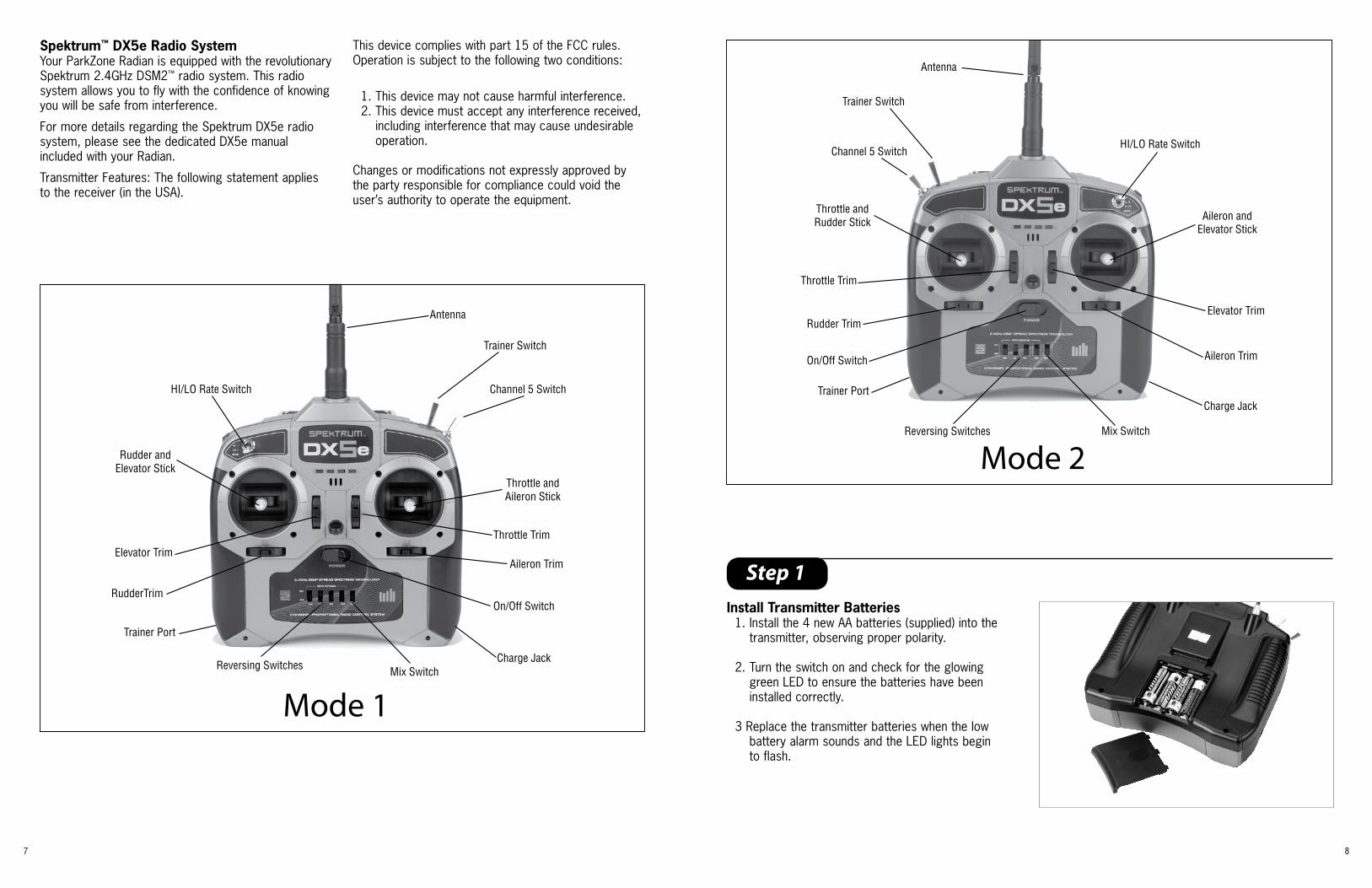
Spektrum™ DX5e Radio SystemYour ParkZone Radian is equipped with the revolutionary Spektrum 2.4GHz DSM2™ radio system. This radio system allows you to fly with the confidence of knowing you will be safe from interference.
For more details regarding the Spektrum DX5e radio system, please see the dedicated DX5e manual included with your Radian.
Transmitter Features: The following statement applies to the receiver (in the USA).
This device complies with part 15 of the FCC rules. Operation is subject to the following two conditions:
1. This device may not cause harmful interference. 2. This device must accept any interference received,
including interference that may cause undesirable operation.
Changes or modifications not expressly approved by the party responsible for compliance could void the user’s authority to operate the equipment.
On/Off Switch
Reversing Switches
Trainer Port
Channel 5 Switch
Throttle andRudder Stick Aileron and
Elevator Stick
Rudder TrimElevator Trim
Throttle Trim
Aileron Trim
HI/LO Rate Switch
Charge Jack
Trainer Switch
Mix Switch
Antenna
Mode 2
On/Off Switch
Reversing Switches
Trainer Port
Channel 5 Switch
Throttle andAileron Stick
Rudder andElevator Stick
Elevator Trim
Throttle Trim
Aileron Trim
RudderTrim
HI/LO Rate Switch
Charge Jack
Trainer Switch
Mix Switch
Antenna
Mode 1

9 10
Step 3
Attaching the WingIn order to attach the wing of your Radian, please follow these simple instructions:
1. Locate the wing spar, as well as the left and right wing panels.
2. Slide the wing spar into the socket located in either the left or right wing panel. Confirm the wing spar is fully seated in the socket.
Note: Use caution when inserting the wing spar into the sockets of the left and right wing panels. Pushing too hard will damage the wing panels.
3. Slide the wing spar and panel through the opening in the fuselage. Slide the wing panel into the fuselage, making sure it is fully seated.
4. Slide the opposite wing panel onto the wing spar. Press the remaining wing panel into the fuselage until it is fully seated. The wing panels are keyed to “lock” when the wing is installed.
Step 2
Charging the Flight BatteryThe Radian comes with a 12V 2-3 cell DC balancing charger and 3S 11.1V 1300mAh Li-Po battery. You must charge the included Li-Po battery pack with a Li-Po specific charger only (such as the included charger). Never leave the battery and charger unattended during the charge process. Failure to follow the instructions properly could result in a fire. When charging, make certain the battery is on a heat-resistant surface.
DC Li-Po Balancing Charger Features• Charges 2- and 3-cell Lithium Polymer
battery packs• Automatically detects incorrect cell count selection• Simple single push-button operation• LED charge status indicator• LED cell balance indicator• Audible beeper indicates power and charge status• 12V accessory outlet input cord
Specifications• Input power: 12V DC, 2A• Charges 2- to 3-cell Li-Po packs with minimum
capacity of 300mA• Variable charge rates from 300mAh to 2 amps
3S 11.1V 1300mAh Li-Po Battery PackThe ParkZone 3S Li-Po battery pack features a balancing lead that allows you to more safely charge your battery pack when used with the included ParkZone Li-Po balancing charger.
To Complete the Charging Process1. Attach the input cord of the charger to the
appropriate power supply (12V accessory outlet), or use the HBZ6513 (optional) and attach to 12V AC power supply. Once your charger has been correctly powered up, there will be an approximate 3-second delay and then you will hear an audible “beep” and the green (ready) LED will flash.
2. Refer to the chart below to select the appropriate charge rates:
Note: When charging the included 1300mAh battery, set the charge rate dial to 1.3A or lower. Selecting a charge rate higher than 1x battery capacity may cause a fire.
3. Select the proper number of cells that you will be charging, either 2 or 3 cells. In the case of the 1300mAh battery included with the Radian, you will select 3 cells.
4. Locate the safety charge lead on the battery pack. The charge lead of a 3-cell Li-Po battery will plug into the larger 4-pin port on the bottom right of the charger. A 2-cell pack will need to plug into the 3-pin port on the bottom left of the charger. Once the battery is properly plugged into the correct port, it will beep 3 times if it is a 3-cell, and twice if it is a 2-cell pack. Once this is done, you are ready to proceed to charge the battery pack.
5. Push the start button to begin the charging process. Once this is done, the charger will make an audible beep that matches the cell count, and then the red (charge) LED will begin to flash. Do not adjust the current once the charger has begun to charge.
Note: At times, the green LED may also flash during the charging process, indicating that the charger is balancing one or more of the cells at the same time it is charging the battery pack. When this is occurring, the red and green LEDs will both be flashing. It will not always be necessary for the cells to be balanced.
6. When the battery pack is fully charged, you will hear an audible beep for about 3 seconds, and the green LED will be solid. Always unplug the battery from the charger immediately upon completion. Failure to do so could cause a fire.
300—400mAh 300mAh500—1000mAh 500mAh1000—1500mAh 1A1500—2000mAh 1.5A2000mAh + 2.0A
BATTERY CAPACITY MAX. CHARGE RATE

11 12
Note: To make trim adjustments to the elevator or rudder:
a. Turn on the transmitter.
b. Plug the fully charged 11.1V 1300mAh battery into the ESC.
c. Use elevator or rudder trim of the transmitter by moving the trim up or down to achieve the tail to be at neutral when the gimbal is also at neutral. If these changes are not sufficient, center the transmitter elevator or rudder trims. Loosen the spool from the control horn and move the control surface back to neutral. Re-tighten the spool.
Warning: Always keep hands and all objects away from the propeller in case the motor is engaged. A moving propeller can cause severe injury and damage.
Attaching the Horizontal Stabilizer1. Locate the horizontal stabilizer.
2. Slide the horizontal stabilizer through the slot between the fuselage and the rudder. Make sure the control horn installed in the elevator will properly align with the pushrod exiting the left side of the fuselage.
3. When you are certain the tail is centered correctly, use the tape provided to properly secure the horizontal stabilizer to the fuselage as shown. Use the tape on the top and bottom of each side of the tail (total of 4 applications).
4. Turn on the transmitter, confirming the throttle stick is in the full down/idle position.
5. Remove the canopy from the fuselage (attached with magnets). Plug the blue EC3 connector installed on the battery into the EC3 device connector installed on the speed control.
6. Install the pushrod through the hole in the keeper. Move the elevator to the neutral position and tighten the keeper. The pushrod keeper comes pre-installed in the outermost hole of the control horn. It is recommended to fly the Radian with the pushrods installed in the default positions until you become more comfortable with the controls.
Step 4 Step 5
Connecting the Rudder Pushrod1. Loosen the pushrod keeper installed on the rudder
control horn. The pushrod keeper comes pre-installed one hole in from the outermost of the control horn.
2. Insert the rudder pushrod through the hole in the keeper. Move the rudder to the neutral position and tighten the keeper.
At this time, your Radian RTF is now complete.Once pre-flight control and range checks have beencompleted, the Radian is ready to fly.
Throttle
Elevator
Rudder
Left Stick
Up/Down
Right Stick
Up/Down
Right Stick
Left/Right
Right Stick
Up/Down
Left Stick
Up/Down
Right Stick
Left/Right
Mode 2 Mode 1

13 14
Step 7
Range TestYou will need two people to perform the range test: one to hold the plane and the other to give the transmitter input.
WARNING: The person holding the plane should hold it in such a way that the propeller does not come into contact with any part of their clothing or body.
To place the transmitter in range check mode, turn the transmitter on. Face the model with the transmitter in your normal flying position. Pull and hold the trainer switch while toggling the HI/LO Rate Switch four times. The LEDs will flash and the alarm will sound indicating the system is in range check mode.
1. One person holds the transmitter while the other person walks 30 paces away with the airplane.
2. Be sure the throttle is in the full down/idle position.
3. Plug the blue EC3 connector on the flight battery into the blue EC3 device connector installed on the speed control.
4. The propeller should spin quickly as soon as the throttle stick is advanced.
5. As the first person moves the transmitter controls, the other person watches to be sure the airplane’s motor and tail controls operate smoothly.
6. Once the range check has been completed, simply release the trainer switch and the transmitter will exit range check mode.
Step 6
Replacing the Propeller1. Using a #0 screwdriver, remove the two screws
installed in the front of the spinner. Remove the spinner cone and place it aside so it does not get lost.
2. Remove the pins installed in the prop blades. Set them aside with the spinner cone so they do not become lost.
3. Replace the prop blades and reinstall the pins. Make sure the pins are flush when installed, otherwise the spinner cone will not install.
4. Reinstall the spinner and confirm it is properly seated. Reinstall the screws in the front of the spinner.

15 16
Step 9
Step 10
30A ESC InstructionsThe E-flite 30A Pro Brushless ESC is a lightweight, high-quality, efficient sensorless brushless electronic speed control with an integrated Switch-Mode BEC. It can oper ate without the need for a separate receiver battery to power your servos and receivers, saving you weight and complication. It is capable of up to 30 amps continuous current when using 3- to 4-series Li-Po battery packs. You can drive up to 5 analog or 4 digital sub-micro-sized servos with the BEC on any recommended input voltage. This ESC also features safe power arming along with advanced programmable features such as low voltage cutoff, braking, timing, throttle input range, and more, making this truly a ‘pro series’ speed control.
Flying the RadianAlways choose a wide-open space for flying your ParkZone Radian. It is ideal for you to fly at an AMA sanctioned flying field. If you are not flying at an AMA approved site, always avoid flying near houses, trees, wires and buildings. You should also be careful to avoid flying in areas where there are many people, such as busy parks or school yards. Always follow local ordinances. We recommend only flying your Radian in light winds.
Prior to each flight• Always make sure your Radian is properly trimmed.• Always make sure the receiver, ESC and battery
are properly secured.• Always verify the propeller is on securely.• Always ensure the servo reversing switches on the
transmitter are set correctly.• Always verify the dual rates switch is set at where
you plan on flying. We recommend LOW rates for your initial flying. The Radian is very maneuverable on high rates and requires a lot of experience to handle properly.
Note: Your Radian 30A ESC comes preprogrammed with the brake on (for proper propeller folding), and the auto-cut set for 3S to match the included battery. For detailed programming instructions, please refer to the E-flite 30A ESC instruction sheet included with the Radian.
Note: ALWAYS assume the motor and the propeller are live. ALWAYS keep clear of the propeller at all times. The high rpm of the brushless motor can cause severe injury.
Center of Gravity LocationThe center of gravity on your Radian should be located approximately 2-1/2 inches (63mm) behind the leading edge of the wing, when measured against the fuselage. This CG location has been determined with the ParkZone 1300mAh 11.1V Li-Po battery installed.
Note: The power system installed in the Radian is designed for climbing use in bursts (50% operating time or less). It is not intended to run full throttle for long periods of time. Not following this direction may result in reduced life of the power system.
After flying, it is important to recharge the Li-Po battery pack included with the Radian. The Li-Po battery pack should always be stored at least 70% charged to prevent damage to the battery pack.
Step 8
ReceiverYour Radian comes equipped with the Spektrum AR500 full range 2.4GHz DSM receiver. The following are the channels that are programmed in the receiver:
Bind Port: Ch. 1: Throttle Ch. 2: Aileron Port #1 Ch. 3: Elevator Ch. 4: Rudder Ch. 5: Gear Ch. 6: Aileron Port #2
Note: This port sends out a duplicate of the aileron signal.
Make certain you plug in the servo leads to the correct corresponding channel. Always perform a function check prior to flying to ensure this.
BindingThe Spektrum DX5e transmitter and AR500 receiver have been bound for you. Should you have a need to re-bind the AR500 to the DX5e or another DSM2
transmitter, please follow the provided instructions.
1. Confirm the flight battery has been unplugged from the ESC and the transmitter is powered off.
2. Insert the bind plug into Batt/Bind port on the AR500 receiver.
3. Connect the blue EC3 connector on the battery to the ESC. The orange LED on the AR500 should begin to blink.
4. Pull forward on the trainer switch located on the DX5e transmitter while powering on the transmitter. The transmitter will emit a series of beeps to confirm it has entered Bind mode. Release the trainer switch.
5. The orange LED will turn to solid when the bind process has completed. Remove the bind plug from the AR500, disconnect the flight battery and power the transmitter off.

17 18
Warranty and Follow-Up ProceduresWarranty Period: Exclusive Warranty- Horizon Hobby, Inc., (Horizon) warranties that the Products purchased (the “Product”) will be free from defects in materials and workmanship at the date of purchase by the Purchaser.
Limited Warranty (a) This warranty is limited to the original Purchaser (“Purchaser”) and is not transferable. REPAIR OR REPLACEMENT AS PROVIDED UNDER THIS WARRANTY IS THE EXCLUSIVE REMEDY OF THE PURCHASER. This warranty covers only those Products purchased from an authorized Horizon dealer. Third party transactions are not covered by this warranty. Proof of purchase is re-quired for warranty claims. Further, Horizon reserves the right to change or modify this warranty without notice and disclaims all other warranties, express or implied.
(b) Limitations- HORIZON MAKES NO WARRANTY OR REPRESENTATION, EXPRESS OR IMPLIED, ABOUT NON-INFRINGEMENT, MERCHANTABILITY OR FITNESS FOR A PARTICULAR PURPOSE OF THE PRODUCT. THE PURCHASER ACKNOWLEDGES THAT THEY ALONE HAVE DETERMINED THAT THE PRODUCT WILL SUITABLY MEET THE REQUIREMENTS OF THE PURCHASER’S INTENDED USE.
(c) Purchaser Remedy- Horizon’s sole obligation hereun-der shall be that Horizon will, at its option, (i) repair or (ii) replace, any Product determined by Horizon to be defective. In the event of a defect, these are the Purchaser’s exclusive remedies. Horizon reserves the right to inspect any and all equipment involved in a warranty claim. Repair or replacement decisions are at the sole discretion of Horizon. This warranty does not cover cosmetic damage or damage due to acts of God, accident, misuse, abuse, negligence, commercial use, or modification of or to any part of the Product. This warranty does not cover damage due to improper installation, operation, maintenance, or attempted repair by anyone other than Horizon. Return of any goods by Purchaser must be approved in writing by Horizon before shipment.
Damage Limits: HORIZON SHALL NOT BE LIABLE FOR SPECIAL, INDIRECT OR CONSEQUENTIAL DAMAGES, LOSS OF PROFITS OR PRODUCTION OR COMMERCIAL LOSS IN ANY WAY CONNECTED WITH THE PRODUCT, WHETHER SUCH CLAIM IS BASED IN CONTRACT, WARRANTY, NEGLIGENCE, OR STRICT LIABILITY. Further, in no event
shall the liability of Horizon exceed the individual price of the Product on which liability is asserted. As Horizon has no control over use, setup, final assembly, modification or misuse, no liability shall be assumed nor accepted for any resulting damage or injury. By the act of use, setup or assembly, the user accepts all resulting liability.
If you as the Purchaser or user are not prepared to accept the liability associated with the use of this Product, you are advised to return this Product immediately in new and unused condition to the place of purchase.
Law: These Terms are governed by Illinois law (without regard to conflict of law principals).
Safety Precautions: This is a sophisticated hobby Product and not a toy. It must be operated with caution and common sense and requires some basic mechanical ability. Failure to operate this Product in a safe and responsible manner could result in injury or damage to the Product or other property. This Product is not intended for use by children without direct adult supervision. The Product manual contains instructions for safety, operation and maintenance. It is essential to read and follow all the instructions and warnings in the manual, prior to assembly, setup or use, in order to operate correctly and avoid damage or injury.
Questions, Assistance, and Repairs: Your local hobby store and/or place of purchase can-not provide warranty support or repair. Once assembly, setup or use of the Product has been started, you must contact Horizon directly. This will enable Horizon to better answer your questions and service you in the event that you may need any assistance. For questions or assistance, please direct your email to [email protected], or call 877.504.0233 toll free to speak to a service technician.
Inspection or Repairs If this Product needs to be inspected or repaired, please call for a Return Merchandise Authorization (RMA). Pack the Product securely using a shipping carton. Please note that original boxes may be included, but are not designed to withstand the rigors of shipping without additional protection. Ship via a carrier that provides tracking and insurance for lost or damaged parcels, as Horizon is not responsible for merchandise until it arrives and is accepted at our facility. A Service Repair
Replacement PartsMake sure that you keep your Radian flying. Replacement parts are available at your local hobby shop or from Horizon Hobby (www.horizonhobby.com). Please try your local hobby shop first. By supporting them, they will be there when you need them.
Item #: Description:PKZ1017 Propeller Blades: RadianPKZ1018 Prop Adapter & Spinner Set: RadianPKZ1033 11.1V 1300mAH LiPo BatteryPKZ1040 2-3 DC LiPo Balancing ChargerPKZ1060 SV80 3-Wire Sub-Micro Servo PKZ4703 Decal Sheet: RadianPKZ4713 Canopy: RadianPKZ4714 Firewall w/Screws: RadianPKZ4716 PKZ 480 Outrunner Brushless Motor: RadianPKZ4720 Main Wing with Spar: RadianPKZ4722 Pushrods with Clevis: RadianPKZ4725 Tail Wing Set: RadianPKZ4767 Bare Fuselage: RadianSPMAR500 DSM2 5CH Sport ReceiverEFLA1030 30-Amp Pro SB Brushless ESC
Option PartsItem #: Description:EFLB12503S 11.1V 1250mAh Li-Po BatteryEFLC505 1-5 Cell Li-Po Charger with BalancerHBZ6513 Alligator Clip: 12V AdapterTHP1205P AC to 12VDC, 5.0A Power Supply: EFLC505SPMP300 Spektrum Neck StrapSPM9525 Spektrum 1500mAh Ni-MH AA (4)SPM9526 Spektrum 150mA Wall Charger
Register your product and receive ParkZone updates at www.parkzone.com

19 20
Request is available at www.horizonhobby.com on the “Support” tab. If you do not have internet access, please include a letter with your complete name, street ad-dress, email address and phone number where you can be reached during business days, your RMA number, a list of the included items, method of payment for any non-warranty expenses and a brief summary of the problem. Your original sales receipt must also be included for warranty consideration. Be sure your name, address, and RMA number are clearly written on the outside of the shipping carton.
Warranty Inspection and Repairs To receive warranty service, you must include your original sales receipt verifying the proof-of-purchase date. Provided warranty conditions have been met, your Product will be repaired or replaced free of charge. Repair or replacement decisions are at the sole discretion of Horizon Hobby.
Non-Warranty Repairs Should your repair not be covered by the warranty, the repair will be completed and payment will be required without notification or estimate of the expense unless the expense exceeds 50% of the retail purchase cost. By submitting the item for repair you are agreeing to payment of the repair without notification. Repair estimates are available upon request. You must include this request with your repair. Non-warranty repair estimates will be billed a minimum of ½ hour of labor. In addition you will be billed for return freight. Please advise us of your preferred method of payment. Horizon accepts money orders and cashiers checks, as well as Visa, MasterCard, American Express, and Discover cards. If you choose to pay by credit card, please include your credit card number and expiration date. Any repair left unpaid or unclaimed after 90 days will be considered abandoned and will be disposed of accordingly. Please note: non-warranty repair is only available on electronics and model engines.
United States: Electronics and engines requiring inspection or repair should be shipped to the following address:
Horizon Service Center 4105 Fieldstone Road
Champaign, Illinois 61822
All other products requiring warranty inspection or repair should be shipped to the following address:
Horizon Support Team 4105 Fieldstone Road
Champaign, Illinois 61822
Please call 877.504.0233 or e-mail us at [email protected] with any questions or concerns regarding this product or warranty.
United Kingdom: Electronics and engines requiring inspection or repair should be shipped to the following address:
Horizon Hobby UK Units 1-4 Ployters Rd
Staple Tye Southern Way
Harlow Essex CM18 7NS United Kingdom
Please call +44 1279 641 097 or [email protected] with any questions or concerns regarding this product or warranty.
Germany:Electronics and engines requiring inspection or repair should be shipped to the following address:
Horizon Technischer Service Otto Hahn Str. 9a 25337 Elmshorn
Germany
Please call +49 4121 46199 66 or [email protected] with any questions or concerns regarding this product or warranty.

• LithiumIonenAkkuSicherheitsrichtlinien
• Directivesdesécuritésurlesaccuslithium-ion
• Indicazionidisicurezzaperlabatteriaagliionilitio
Lithium Ion Battery Safety Guidelines
ENALLINSTRUCTIONANDPRECAUTIONSMUSTBE
READANDFOLLOWEDEXACTLY.
WARNING:PROCEDURES,WhIChIFNOTPROPERLYFOLLOWED,CREATEThEPROBABILITYOFPROPERTYDAMAGE,COLLATERALDAMAGEANDSERIOUS
INjURYORCREATEAhIGhPROBABILITYOFSUPERFICIALINjURY.
Failuretoexercisecarewhileusingthisproductandcomplywiththefollowingconditionsandguidelinescouldresultinproductmalfunction,excessiveheat,fire,propertydamage,andultimatelyinjury.
LithiumIonbatteriesarenottoys.ForthepurposesofthisdocumentLi-Ion,Li-PoorLi-Febatterieswillbedescribedas“Batteries.”
Handling and Storage• Neveralter,punctureorimpactBatteriesor
relatedcomponents.• Donotdirectlyconnecttheterminalswithmetal
objects.Thiswillshort-circuitBatteries,resultinginheatandelectricaldischarge.
• NeverstorelooseBatteriestogether,theBatteries’terminalsmaycontactoneanothercausingashortcircuit.
• NeverexposeBatteriestoextremetemperaturesordirectsunlight.Thetemperaturerangemustbebetween40–120°F(4–49°C).
• AlwaysverifyvoltageofBatteriesthathavebeenoutofserviceforgreaterthansix(6)months.
• AlwaysdisconnectBatterieswhennotinuseandstoreBatteriesinanon-conductiveandfireproofcontainer.
• Forbestresults,storeBatteriesatapproximately1/2ofthecapacitylistedontheBatteries’label.
Before the First Charge• Makeavisualandphysicalinspectionof
Batteriesforanydamagedorlooseleadsorconnectors,damagedpackaging,orotherirregularitieswhichmaycauseashortcircuitandeventualfire.
• VerifythatthepositiveterminaloftheBatteriesisconnectedtothepositiveterminalofthecharger.Confirmpolaritywithavoltmeterifunsure.
• CheckthevoltageofBatteriesusingavoltmetertomakesureBatterieshavethevoltageofthecapacitylistedonBatteries’label.
Charging
Formorecompletechargingguidelinespleaserefertoyourcharger’smanual;however,thewarningsandguidelineslistedbelowmustbefollowedtoavoidpropertydamageandinjury.• Alwaysuseacompatiblebalancedmode
charger,specificallydesignedforthechemistryofbatteryyouareusing.
• AlwayschargeBatteriesinanopenareaawayfromflammablematerials,liquidsandsurfaces.
• NeverchargeBatteriesinsideofthemodel.• NeverchargeBatteriesthatarehottothetouch
(above100°F).DONOThandleBatteriesuntiltheyarecool.
• Alwayssetthechargertothepropercellcountand/orvoltagelistedonBatteries’labels.
• AlwayssetthechargertotheampchargerateaslistedonBatteries’labels.ThechargershouldneverbesettochargeBatteriesatarategreaterthan1C(One(1)timesthecapacityofBatteriesinamphours)unlessanotherCrateisspecified
inthemanufacturer’sproductdocumentationortherateispresetaspartofaspecificbatteryandchargercombination.DONOTalterthechargerateoncecharginghasbegun.
• AlwayscheckthevoltageofBatteriesbeforeeachchargesessioninordertoensuretheyareatorabovetheminimumsafestartingvoltage.IfstartingvoltageisbelowrecommendedlevelsthenBatterieshavebeenoverdischargedorhaveexperiencedafailureandshouldNOTbecharged.
• NeveroverchargeBatteriesbeyondthecapacitylistedonBatteries’labels.
• Alwaysensureyourbatteryhasabalancingleadandthatitisinsertedinthecorrectportofyourchargerbeforecharging.
Thepreinstalled2-pinjST,EC3orEC5connectorsandwiregaugesonyourbatterieshavebeentestedandmatchedtotypicalusageinradiocontrolapplications,thoughthebatteriesmayhavehighercapacities.Theseconnectorsdohavepowerlimitationsinthatyourbatterymayproducemorepowerundercertaincircumstancesthanwhattheconnectorisabletowithstand.Ifyouwillbeusingahorizonhobbybatteryinanyapplicationthatwillexceedtheconnector’spowercapabilities,itisyourresponsibilitytoensurethatyoureplacetheconnectorwithaproductbettersuitedtothehigherratingsyouareusing.
Safety
IfatanytimeBatteriesbecomedamaged,hot,orbegintoballoonorswell,discontinuecharging(ordischarging)immediately.Quicklyandsafelydisconnectthecharger.ThenplacetheBatteriesand/orchargeinasafe,openareaawayfromflammablematerialsinanapprovedLi-Pobagtoobserve.Afteronehour,removetheBatteriesfromservice.DONOTcontinuetohandle,attempttouse,orshiptheBatteries.FailuretofollowtheseprocedurescancausedamagetoBatteries,personalpropertyorcauseseriousinjury.
DamagedorswollenBatteriescanbeunstableandveryhot.DONOTtouchBatteriesuntiltheyhavecooled.DisposeofBatteriesinthemannerrequiredbyyourcity,county,stateorcountry.ContacttheappropriatehorizonProductSupportofficetospeaktoaservicetechnicianformoreinformation.
Intheeventoffire,aClassD,drychemicalfireextinguishermustbeusedthenbatteriesmustbeplacedinsideofanapprovedLi-Pobag.
Discharging• NeverdischargeBatteriesatamperagerates
higherthanspecifiedonBatteries’labels.• NeverallowthetemperatureofBatteriesto
exceed160°Fduringdischarge.AdequatecoolingforBatteriesisrequired,especiallywhendischargingatornearmaximumrates.
• NeverdischargeBatteriestovoltagebelowwhichtheyareratedbythemanufacturerwhenmeasuredunderload(connectedtothevehicleorachargercapableofdischarge).Batteriesdischargedtoavoltagelowerthanthelowestapprovedvoltagemaybedamaged,resultinginlossofperformanceandpotentialfirewhenBatteriesarecharged.
Additional Guidelines and Warnings
Intheeventofacrash,alwaysquicklyandsafelydisconnectandremoveBatteriesfromthemodel.Thenfollowthepreviouslylistedsafetyprocedures.• IftheinternalcontentsofBatteriescomeinto
contactwithyourskin,washtheaffectedarea(s)withsoapandwaterimmediately.Ifitcomesintocontactwithyoureye(s),flushthemwithgenerousamountsofwaterfor15minutesandseekimmediatemedicalattention.
Battery Limited Warranty
Allinstructions,warrantiesandothercollateraldocumentsaresubjecttochangeatthesolediscretionofhorizonhobby,Inc.Foruptodateproductliterature,visitwww.horizonhobby.com.
Warranty PeriodExclusiveWarranty-horizonhobby,Inc.,(horizon)warrantiesthattheProductspurchased(the“Product”)willbefreefromdefectsinmaterialsandworkmanshipatthedateofpurchasebythePurchaser.
Limited WarrantyHorizon reserves tHe rigHt to cHange or modify tHis warranty witHout notice and disclaims all otHer warranties, express or implied.
(a)ThiswarrantyislimitedtotheoriginalPurchaser(“Purchaser”)andisnottransferable.REPLACEMENTASPROVIDEDUNDERThISWARRANTYISThEEXCLUSIVEREMEDYOFThEPURChASERThiswarrantycoversonlythoseProductspurchasedfromanauthorizedhorizondealer.Thirdpartytransactionsarenotcoveredbythiswarranty.Proofofpurchaseisrequiredforwarrantyclaims.
(b)Limitations-hORIZONMAKESNOWARRANTYORREPRESENTATION,EXPRESSORIMPLIED,ABOUTNONIFRING-EMENT,MERChANTABILITYORFITNESSFORAPARTICULARPURPOSEOFThEPRODUCT.ThEPURChASERACKNOWL-EDGESThATThEYALONEhAVEDETER-MINEDThATThEPRODUCTWILLSUITABLYMEETThEREQUIREMENTSOFThEPURChASER’SINTENDEDUSE.
(c)PurchaserRemedy-horizon’ssoleobligationhereundershallbethathorizonwill,atitsoption,replaceanyProductdeterminedbyhorizontobedefectiveIntheeventofadefect,thisisthePurchaser’sexclusiveremedy.
Replacementdecisionsareatthesolediscretionofhorizon.ThiswarrantydoesnotcovercosmeticdamageordamageduetoactsofGod,accident,misuse,abuse,negligence,commercialuse,ormodificationofortoanypartoftheProduct.Thiswarrantydoesnotcoverdamageduetoimproperinstallation,operation,maintenanceorattemptedrepairbyanyone.HORIZON DOES NOT INSPECT OR REPAIR BATTERIES. NEvER SHIP BATTERIES TO HORIZON.
Damage Limits
hORIZONShALLNOTBELIABLEFORSPECIAL,INDIRECTORCONSEQUENTIALDAMAGES,LOSSOFPROFITSORPRODUCTIONORCOMMERCIALLOSSINANYWAYCONNECTEDWIThThEPRODUCT,WhEThERSUChCLAIMISBASEDINCONTRACT,WARRANTY,NEGLIGENCE,ORSTRICTLIABILITY.Further,innoeventshalltheliabilityofhorizonexceedtheindividualpriceoftheProductonwhichliabilityisasserted.Ashorizonhasnocontroloveruse,setup,finalassembly,modificationormisuse,noliabilityshallbeassumednoracceptedforanyresultingdamageorinjury.Bytheactofuse,setuporassemblytheuseracceptsallresultingliability.
IfyouasthePurchaseroruserarenotpreparedtoaccepttheliabilityassociatedwiththeuseofthisProduct,youareadvisedtoreturnthisProductimmediatelyinnewandunusedconditiontotheplaceofpurchase.
Law:TheseTermsaregovernedbyIllinoislaw(withoutregardtoconflictoflawprincipals).
Questions and Assistance
Yourlocalhobbystoreand/orplaceofpurchasecannotprovidewarrantysupportorreplacement.horizonwillreplaceProduct,freeofcharge,ifithasadefectinmaterialsorworkmanshipatthedateofpurchase.Ifthisisthecasecontacthorizonhobby.PleasedirectyouremailtoyournearestProductSupportrepresentative.
INSTRuCTIONS FOR DISPOSAL OF WEEE By uSERS IN THE EuROPEAN uNION.
Thisproductmustnotbedisposedofwithotherwaste.Instead,itistheuser’sresponsibilitytodisposeoftheirwasteequipmentbyhandingitovertoadesignatedcollectionpointfortherecycling
ofwasteelectricalandelectronicequipment.Theseparatecollectionandrecyclingofyourwasteequipmentatthetimeofdisposalwillhelptoconservenaturalresourcesandensurethatitisrecycledinamannerthatprotectshumanhealthandtheenvironment.Formoreinformationaboutwhereyoucandropoffyourwasteequipmentforrecycling,pleasecontactyourlocalcityoffice,yourhouseholdwastedisposalserviceorwhereyoupurchasedtheproduct.
DE WARNUNG
SIEMÜSSENALLEINSTRUKTIONENUNDSIChERhEITShINWEISESORGFÄLTIGDURChLESEN
UNDIhNENFOLGELEISTEN.
WARNUNG:TÄTIGKEITENDIENIChTWIEBESChRIEBENAUSGEFÜhRTWERDEN,
KöNNENZUBESChÄDIGUNGENANEIGENEMUNDFREMDENEIGENTUMFÜhRENSOWIEZU
SChWERENVERLETZUNGEN.
Falscher,nichtsachgemäßerUmgangoderdasNichtbefolgenodernichtlesendieserAnweisungen,kannFehlfunktionen,extremehitze,Feuer,SachbeschädigungoderVerletzungenzurFolgehabe.
LithiumIonenAkkussindkeineSpielzeuge.Begriffs/Wortwahl:IndiesemDokumentwerdenLi-Ion,Li-PoAkkusundLi-FeAkkusalsAkkusbezeichnet.
Lagerung und Gebrauch.• Stechen,DrückenoderBauenSieniemalsAkkus
oderdamitverbundenenKomponentenum.• BringenSiekeinemetallischenGegen-
ständeindenKontaktmitdemAkkupolenoderAnschlüssen.DiesewürdedenAkkukurzschließenundzueinerhitzeentwicklungundelektrischerEntladungführen.
• LagernSieniemalsloseAkkusmiteinander.DieAkkupolekönntensichdabeiberührenundeinenKurzschlußerzeugen.
• SetzenSieniemalsAkkusextremenTemperaturenoderdirekterSonneneinstrahlungaus.DerTemperaturbereichsolltezwischen4°-49°Celsiusliegen.
• ÜberprüfenSieimmerdieSpannungvonAkkusdielängeralssechs(6)Monatenichtgebrauchtwurden.
• TrennenSieimmerAkkuverbindungen,wenndiesenichtbenutztwerden.
• FürbesteErgebnisselagernSiedieAkkusmitderhälftederaufdemEtikettKapazität.
Richtlinien vor dem ersten Laden• ÜberprüfenSieobderAkkuoderdessen
Verpackungbeschädigtist.ÜberprüfenSieobdieAnschlüsseoderandereUrgelmäßigkeiten,diesonstzueinemKurzschlussoderFeuerführenkönnen.
• StellenSiesicherdassderPluspolanschlußdesAkkusmitdemPluspolanschlußdesLadegerätesverbundenist.ÜberprüfenSiediePolaritätdesAkkusmiteinemVoltmeter,wennSiesichnichtsichersind.
• ÜberprüfenSiemiteinemVoltmeter,obdieaufdemEtikettaufgedruckteSpannungdertatsächlichenentspricht.
Richtlinien für das Laden
FürausführlicheundkompletteRichtlinienzumLadenlesenSiebittedieBedienungsanleitungIhresLadegerätes.SiemüssendenfolgendenWarnungenundRichtlinienFolgeleistenumVerletzungenundSachbeschädigungenzuvermeiden.• VerwendenSieimmereinLadegerät,dasszu
demLadenderAkkusgeeignetist.• LadenSieimmerAkkusaufeinerfreienFläche,
weitwegvonbrennbarenFlüssikeitenoderOberflächen.
• LadenSieniemalsAkkusimModelloderimeinemechtenFahrzeug.
• LadenSieniemalsAkkusdiezuheißzumAnfassensind(über38°)LassenSiedieAkkusruhenbissieabgekühltsind.
• StellenSieimmerdasLadegerätaufdiekorrekteZellenzahlund/oderVoltzahlein,dieaufdemAkkuetikettbeschriebenist.
• StellenSiedenLadestromimmeraufdieAmperezahlein,dieaufdemAkkuetikettoderinderBedienungsanleitungvorgeschriebenwird.DasLadegerätsollteniemalsaufeinenLadestromgrößerals1C(1CentsprichtderAkkukapazitätinAh)eingestelltwerden,solangekeinandererLadestromaufdemEtikettoderBedienungsanleitungvorgeschriebenwird.VerändernSiedenLadestromnicht,wennderLadevorgangbegonnenhat.
• ÜberprüfenSievorderLadungimmerdieBatteriespannungumsicherzustellen,dassdiesenichtunterderMindestspannungist.SolltedieAkkuspannungunterderemfohlenenMindestspannungsein,istdieseeinErgebniseinerTiefentladungoderAusfall.TiefentladeneoderdefekteAkkusdürfennichtgeladenwerden.
• AkkusdürfennichtüberdieaufdemEtikettbeschriebenenKapazitätgeladenwerden.
• BittestellenSiesicherdassderAkkumiteinemBalancersteckerausgestattetunddieservordemLadenindenrichtigenAnschlußeingestecktwordenist.
Dervorinstallierte2PinjST,EC3oderEC5AkkuanschlußunddieKabelstärkesindfürdentypischenEinsatzinRCAnwendungenvorgesehenundgetestetworden,auchwenndieAkkushöhereKapazitätenhaben.DieseAnschlüssehabenLeistungsgrenzendievomAkkuunterbestimmenVoraussetzungen/Anwendungenübertroffenwerdenkönnen.SolltenSieeineAnwendunghabenfürdiedaszutreffendist,liegtesalleininihrerVerantwortungeinenAnschlußzuwählenderfürdiehöherenStrömebessergeeignetist.
Sicherheitsrichtlinien
SolltezuirgendeinemZeitpunktderAkkubeschädigtwerden,anfangenzuzischenoderzurauchenbeendenSiesofortdenBetrieb,dasEntladenoderLaden.
TrennenSiedenAkkuschnellundsichervomLadegerät.LegenSiezurBeobachtungdenAkkuundmitoderohneLadegerätaneinensicherenoffenenOrtineinenLiPoBeutel,weitwegvonentflammbarenMaterialien.NacheinerStundekannderAkkuentferntwerden.DieserAkkudarfnichtweiterverwendetwerden.hantierenSienichtweitermitdiesemAkkuundversendenSieihnnicht.EinNichtbefolgendieserAnweisungenkannweitereBeschädigungamAkku,FeueroderernsthafteVerletzungenzurFolgehaben.AufgeblähteodergeschwolleneAkkussindinstabilundsehrheiß.FassenSiedieseAkkusnichtanbissieabgekühltsind.EntsorgenSiedieAkkusgemäßderEntsorgungsrichtlinienihresLandesoderBundeslandesoderStadt.KontaktierenSiedentechnischenServicevonhorizonhobbyfürmehrInformation.
NutzenSieimBrandfalleinenKlasseDPulverFeuerlöscheroderplacierenSiedenAkkuineinemzugelassenLiPoBeutel.
Richtlinien zum Entladen
EntladenSieniemalsdenAkkumithöherenEntladeströmenalsaufdemEtikettangeben.• LassenSiewährenddemEntladenniemalsdie
Temperaturüber71°steigen.AufeineadäquateKühlungdesAkkusistachten,geradedannwennSiedenAkkuandenmaximalenEntladegrenzenbetreiben.
• EntladenSieniemalsdenAkkuunterdiemaximaleEntladespannungunterLast(BeidemBetrieboderwährenddesEntladensdurchdasLadegerät)TiefentladeneAkkuskönnendurchdieTiefentenladungbeschädigtsein,anLeistungverlierenundbeidemLadenFeuerfangen.
Zusätzliche Warnungen und Sicherheitshinweise• ImFalleeinesChrashoderAbsturzestrennen
SieschnellundsicherdenAkkuundentnehmenSieihndemModell.FolgenSiedanndenbeschriebenenSicheheitsrichtlinien.
• SolltenSiemitAkkuflüssigkeitinBerührungkommen,waschenSieunverzüglichdiebetreffendenhautpartiengründlichmitWasserundSeife.
Garantieeinschränkungen
AlleDokumente,AussagenundhinweisebezüglichGarantiebestimmungenunterliegenden
ÄnderungenderhorizonhobbyInc.FürdieneuestenProduktinformationenundGarantiebestimmungenkontaktierenSiebittewww.horizonhobby.com
Garantie Periode
ExklusiveGarantie-horizonhobbyIncgarantiert,dassdasvomKäufergekaufteProdukte(“dasProdukt”)freivonMaterial-undherstellungsfehlernist.
Eingeschränkte Garantie
horizonbehältsichdasRechtvor,dieseGarantiebestimmungzujedemZeitpunktohnevorherigeAnkündigungzuändern,wodurchallevorherigenBestimmungenihreGültigkeitverlieren.
(a)DieGarantiebeschränktsichaufdenErstkäuferundistnichtübertragbar.ErsatzlieferungenunterdieserGarantiebestimmungistalleinigerAnspruchdesErstkäufers.DieGarantieumfasstnurdieProdukte,diebeieinemautorisiertenhorizonhändlergekauftwurden.DrittverkäufesindvonjeglichemGarantieanspruchausgenommen.EinKaufnachweisisterforderlich.
(b)Einschränkungen-horizongibtkeineGarantie,ausgesprochenoderangenommen,aufNichtverletzungderNutzung,VerkaufsfähigkeitoderdenZustandfüreinebestimmteAnwendungdesProduktes.DerKäuferstimmtzu,dasseralleinüberdieerforderlicheVerträglichkeitdesProduktesmitseinerAnwendungbestimmt.
(c)AnsprüchedesKäufers-EsisthorizonseinzigeVerpflichtungnacheigenemErmessenundeigenerPrüfungdasProduktzuersetzen.DiesistimSchadensfalldereinzigeAnspruchdesKäufers.DieEntscheidung,Ersatzzuliefern,liegtausschließlichimErmessenvonhorizon.DieGarantieschließtkosmetischeSchädenaus,oderSchädendurchhöhereGewalt,Unfälle,Missbrauch,Zerstörung,Nicht-beachten,kommerziellenEinsatzoderModifikationenzuirgendeinemTeildesProduktes.HORIZON INSPIZIERT ODER REPARIERT AkkuS NICHT. SCHICkEN SIE NIEmALS AkkuS ZuRüCk.
Schadenseinschränkung
horizonistnichthaftbarfürspezielle,indirekteoderFolgeschäden,AusfallvonGewinnenoderProduktionoderkommerziellerVerluste,dieimZusammenhangmitdemProduktstehen,selbstwennderSchadensanspruchaufeinenVertrag,GarantieoderschlichtGewährleistungberuht.WeiterhinbeschränktsichderAnspruchaufmaximaldenindividuellenPreisdesProduktes.horizonhatkeinenEinflussaufdieAnwendung,denEinbauoderdieEndmontage,diefalscheAnwendungoderModifikationen.IndiesenFällenentfälltjederGarantieanspruchoderjeglicheAnnahmeeinessolchenoderAnsprüchebezüglichVerletzungoderFolgeschäden.DurchdieAnwendung,deinEinbauoderdieMontageselbstakzeptiertderKäuferdieseBestimmungen.
WennSiealsKäuferdieseGarantiebestimmungennichtakzeptierenundannehmenwollen,solltenSiedasProduktinseinerOriginalverpackungunbenutztIhremVerkäuferzurückgeben.
Fragen und HilfeWennIhrlokalerModellbauladenIhnennichtweiterhelfenkann,könnenSiesichanunswenden.horizonwirddasProduktbessernnacheigenemErmessenoderersetzen,sollteeinmaterialoderFabrikationsfehlervorliegen.WendenSiesichandentechnischenService.
ENTSORGuNG IN DER EuROPäISCHEN uNION
DiesesProduktdarfnichtüberdenhausmüllentsorgtwerden.EsistdieVerantwortungdesBenutzers,dassProduktaneinerregistriertenSammelstellefürElektroschrottabzugebendieseVerfahrenstelltsicher,dassdieUmweltgeschontwirdundnatürlicheRessourcennichtüberdieGebührbeanspruchtwerden.DadurchwirddasWohlergehendermenschlichenGemeinschaftgeschützt.FürweitereInformationen,woderElektromüllentsorgtwerdenkann,könnenSieIhrStadtbürooderIhrenlokalenEntsorgerkontaktieren.
FR AVERTISSEMENT
TOUTESLESINSTRUCTIONSETPRECAUTIONSDOIVENTETRELUESETRESPECTEES
SCRUPULEUSEMENT.
AVERTISSEMENT:LENON-RESPECTDESPROCÉDURESAUGMENTELERISQUEDEDÉGÂTSMATÉRIELS,DEDÉGÂTS
INDIRECTSETDEBLESSURESGRAVESOUSUPERFICIELLES.
L’absencedeprécautionsdurantl’utilisationdeceproduitetlenon-respectdesconditionsetdirectivessuivantespeuventprovoquerundysfonctionnementduproduit,unechaleurexcessive,unincendie,desdégâtsmatérielsoudesblessures.
Lesaccuslithium-ionnesontpasdesjouets.Pourlesbesoinsdecedocument,lesaccusLi-ion,Li-PoouLi-Fesontregroupéssousl’expression«accus».
Directives et avertissements liés à la manipulation et à la conservation• Lesaccusetcomposantssimilairesnedoivent
jamaisêtremodifiés,perforésouécrsés.• Nejamaismettrelesconnecteursdirectement
encontactavecdesobjetsmétalliques.Celacourtcircuiteraitl’accucausantunesurchauffeetunefortedécharge.
• Lesaccusnedoiventjamaisêtreconservésensemble,carleursbornespeuventsetoucheretprovoqueruncourt-circuit.
• Lesaccusnedoiventjamaisêtreexposésàdestempératuresextrêmesouàlalumièredirectedusoleil.Latempératuredoitêtrecompriseentre4et49°C(40-120°F).
• Vérifieztoujourslatensiondesaccusquin’ontpasétéutilisésdepuisplusdesix(6)mois.
• Lesaccusnonutilisésdoiventtoujoursêtredéconnectésetconservésdansuneboîtenonconductriceetignifugée.
• Pourdemeilleursrésultats,lesaccusdoiventêtreconservésàlamoitiéenvirondelacapacitéindiquéesurleurétiquette.
Directives et avertissements avant la p remière charge• Contrôlervisuellementlesaccusàlarecherche
decordonsouconnecteursendommagésoumalfixés,deboîtiersdétériorésoud’autresanomaliessusceptiblesdeprovoqueruncourt-circuitet/ouunincendie.
• VérifiezquelabornepositivedesaccusestraccordéeàlabornepositiveduchargeurConfirmezlapolaritéaumoyend’unvoltmètreencasdedoute.
• Mesurezlatensiondesaccusaumoyend’unvoltmètrepourvérifierqu’ellecorrespondàlacapacitéindiquéesurleurétiquette.
31457.2

Directives et avertissements liés à la charge
Pourdesdirectivespluscomplètesconcernantlacharge,reportez-vousaumanueldevotrechargeur;toutefois,lesavertissementsetdirectivesrépertoriéscidessousdoiventêtrerespectéspouréviterdesdégâtsmatérielset/oudesblessures.• Utiliseztoujoursunchargeuréquilibreur
compatiblespécialementconçupourchargercesaccus.Cesaccusnedoiventjamaisêtrechargésenrégimelent(sousintensitéfaible).
• Lesaccusdoiventtoujoursêtrechargésdansunespaceouvert,àl’écartdesmatières,liquidesetsurfacesinflammables.
• Lesaccusnedoiventjamaisêtrechargésàl’intérieurd’unmodèle.
• Nechargezjamaisd’accuschaudsautoucher(dontlatempératureestsupérieureà38°C[100°F]).LesaccusNEDOIVENTPASêtremanipuléstantqu’ilsn’ontpasrefroidi.
• Lechargeurdoittoujoursêtreréglésurlenombred’élémentset/oulatensioncorrectsindiquéssurl’étiquettedesaccus.
• Régleztoujourslechargeuravecletauxdechargeindiquésurl’étiquettedesbatteries.Ilnedoitpasêtreréglésurunechargesupérieureà1C(1foislacapacitédelabatterieenAmp/heure)tantqu’unautretauxdechargen’estpasspécifiédansladocumentationproduitduconstructeurouqueletauxestpré-réglépourunecombinaisondebatterieetdechargeurspécifique.NEPASmodifierletauxdechargedèsquelachargeacommencé.
• Vérifieztoujourslatensiondesaccusavantchaquechargepourvérifierqu’elleatteintoudépasselatensionminimalededébutdechargeensécurité.Silatensiondedébutdechargeestinférieureauniveaurecommandé,alorslesaccussonttropdéchargésoudétériorésetNEDOIVENTPASêtrechargés.
• Lesaccusnedoiventjamaisêtrechargésaudelàdelacapacitéindiquéesurleurétiquette.
• Toujoursvérifierquevotrebatteriepossèdeuneprised’équilibrageetqu’elleestinséréedansleportcorrespondantduchargeuravantdecommencerlacharge.
LasectiondescâblesetlesprisesjST,EC3ouEC5ontététestéetdimensionnépourlesapplicationsdansledomainedesmodèlesréduits,bienquelesbatteriesontdescapacitéssupérieures.Cesprisessontlimitéesniveaupuissance,labatteriepeuproduireplusd’énergiedanscertainescirconstancesetlapriseseracapablederésister.Sivoussouhaitezutiliserunebatteriehorizonhobbypouruneapplicationdépassantleslimitesdepuissancesupportéesparleconnecteur,ilestdevotreresponsabilitéderemplacerlapriseparunmodèlesurdimensionnécorrespondantàvotreutilisation.
Directives et avertissements liés à la sécurité
Siàunmomentquelconque,lesaccussedétériorent,s’échauffent,sedilatentougonflent,interrompezimmédiatementlacharge(ouladécharge).Débranchezrapidementlechargeurentoutesécurité.Placezensuitelesaccuset/oulechargeurenlieusûretouvert,àl’écartdesmatièresinflammables,dansunsachetspécialpouraccusLi-Popourobserverl’évolution.Aprèsuneheure,retirezlesaccus.LesaccusNEDOIVENTPLUSêtremanipulés,utilisésouexpédiés.Lenonrespectdecesprocédurespeutprovoquerdesdégâtsauxaccusetauxbiensoudesblessuresgraves.
Lesaccusdilatésougonfléspeuventêtreinstablesettrèschauds.LesaccusgonflésNEDOIVENTPASêtremanipuléstantqu’ilsn’ontpasrefroidi.Lesaccusdoiventêtreéliminésconformémentàlaréglementationdevotreville,comté,étatoupays.Pourdesinformationssupplémentaires,contactezlebureaud’assistanceproduithorizondevotrerégionpourconsulteruntechnicienduserviceaprèsvente.Encasd’incendie,unextincteuràpoudredeclasseDdoitêtreutilisé,oulesaccusdoiventêtreplacésdansunsachetspécialpouraccusLi-Po.
Directives et avertissements liés à la décharge• Nedéchargezjamaisd’accusàdesampérages
supérieursàceuxspécifiéssurleursétiquettes.• Latempératuredesaccusnedoitjamais
dépasser70°C(160°F)pendantladécharge.Lesaccusdoiventêtrerefroidisdemanièreadéquate,enparticulierlorsdesdéchargesàdestauxprochesdumaximum.
• Lesaccusnedoiventjamaisêtredéchargésjusqu’àunetensioninférieureàcelledéfinieparlefabricantlorsqu’elleestmesuréesouscharge(connectéeauvéhiculeouàunchargeurcapablededécharger).Lesaccusdéchargésjusqu’àunetensioninférieureàlatensionapprouvéelaplusfaiblepeuventêtreendommagésetentraînerunebaissedeperformance,voireunincendielorsquelesaccussontchargés.
Directives et avertissements supplémentaires• Encasd’accident,déconnectezlesaccus
rapidementetensécurité,puisretirez-lesdumodèle.Suivezensuitelesprocéduresdesécuritéci-dessus.
• Encasdecontactcutanéavecdelamatièreàl’intérieurdesaccus,rincezimmédiatementlaouleszonestouchéesàl’eausavonneuse.Encasdecontactaveclesyeux,rincez-lesabondammentàl’eaupendant15minutesetconsultezimmédiatementunmédecin.
Garantie limitée des accus
Touteslesinstructions,garantiesetautresdocumentssontsujetsàmodificationàlaseulediscrétiondehorizonhobby,Inc.Pourobtenirdeladocumentationproduitàjour,consultezlesiteWebwww.horizonhobby.com.
Durée de la garantie
Garantieexclusive-horizonhobby,Inc.(horizon)garantitqueleProduitacheté(le«Produit»)estexemptdevicedematièreetdefabricationàsadated’achatparl’Acheteur.
Garantie limitée
horizonseréserveledroitdemodifierlaprésentegarantiesansavispréalableetdésavouetouteautregarantie,expliciteouimplicite.
(a)Cettegarantieestlimitéeàl’acheteurinitial(«Acheteur)etn’estpastransférable.UNREMPLACEMENTCONFORMEMENTALAPRESENTEGARANTIECONSTITUELESEULRECOURSDEL’AChETEUR.CettegarantiecouvreuniquementlesProduitsachetésauprèsd’unrevendeurhorizonagréé.Lestransactionsentretiersnesontpascouvertesparcettegarantie.Unepreuved’achatestexigéepourlesréclamationsengarantie.(b)Restrictions-hORIZONNEDONNEAUCUNEGARANTIEEXPLICITEOUIMPLICITEQUANTALANONCONTREFACON,ALAQUALITEMARChANDEOUAL’APTITUDEDUPRODUITAUNEQUELCONQUEAPPLICATION.L’AChETEURRECONNAITQU’ILADETERMINE-SEULQUELEPRODUITREPONDRADEMANIEREAPPROPRIEEAUXEXIGENCESDEL’UTILISATIONQU’ILENENVISAGE.
(c)Recoursdel’Acheteur-Dansleprésentcadre,laseuleobligationd’horizonconsistera,àsadiscrétion,àremplacertoutProduitquiauraétéreconnudéfectueuxparsessoins.Ils’agitlàduseulrecoursdel’Acheteurencasdedéfaut.Lesdécisionsderemplacementrelèventdelaseulediscrétiond’horizon.Cettegarantienecouvrepaslesdommagesesthétiquesoulesdommagesdusàdescasdeforcemajeure,àdesaccidents,àuneutilisationincorrecteouabusive,àlanégligence,àuneutilisationcommercialeouàlamodificationd’unquelconqueélémentduProduit.Cettegarantienecouvrepaslesdommagesdusàuneutilisation,unemanipulationouunentretienincorrectsouencoreàunetentativederéparation.HORIZON NE CONTRÔLE PAS LES ACCuS ET NE LES REPARE PAS. N’ENvOyEZ jAmAIS ACCuS à HORIZON.
Limites des dommageshORIZONNESAURAITETRETENUPOURRESPONSABLED’UNQUELCONQUEPREjUDICESPECIAL,INDIRECTOUIMMATERIEL,MANQUEAGAGNER,BAISSEDEPRODUCTIONOUPERTECOMMERCIALELIED’UNEQUELCONQUEFACONAUPRODUITETCE,QU’UNETELLERECLAMATIONSOITFONDEESURUNCONTRAT,UNEGARANTIE,UNENEGLIGENCEOUUNERESPONSABILITEDIRECTE.Parailleurs,laresponsabilitéd’horizonnesauraitenaucuncasdépasserleprixunitaireduProduitpourlequelelleestengagée.Etantdonnéqu’horizonnepeutexercerdecontrôlequantàl’utilisation,auréglage,àl’assemblagefinal,àlamodificationouàl’utilisationincorrecteduProduit,horizondéclinetouteresponsabilitéencasdedommageoublessureenrésultant.Enutilisant,enréglantouenassemblantleProduit,l’utilisateuraccepted’endossertouteresponsabilitéendécoulant.
Si,entantqu’Acheteurouutilisateur,vousn’êtespasdisposéàaccepterlaresponsabilitéassociéeàl’utilisationdeceProduit,vousêtesinvitéàlerenvoyerimmédiatementenétatneufetnonutiliséaulieud’achat.Questions et assistanceVotremagasinlocald’articlesdeloisiret/oulevendeurduproduitnepeuventfournird’assistanceoud’échangesousgarantie.horizonremplaceleproduitsansfraisencasdevicedematièreoudefabricationàladated’achat.Sitelestlecas,contactezhorizonhobby.Adressezvotremessageélectroniqueaureprésentantdel’assistanceproduitleplusproche.
INSTRuCTIONS RELATIvES à L’éLImINATION DES D3E POuR LES uTILISATEuRS RéSIDANT DANS L’uNION EuROPéENNE
Ceproduitnedoitpasêtreéliminéavecd’autresdéchets.Ilincombeàl’utilisateurd’éliminerleséquipementsrebutésenlesremettantàunpointdecollectedésignéenvuedurecyclagedesdéchetsd’équipementsélectriquesetélectroniques.Lacollecteetlerecyclageséparésdevoséquipementsusagésaumomentdeleurmiseaurebutaiderontàpréserverlesressourcesnaturellesetàassurerlerecyclagedesdéchetsdemanièreàprotégerlasantéhumaineetl’environnement.Pourplusd’informationssurlespointsdecollectedevoséquipementsusagésenvuedurecyclage,veuillezcontactervotremairie,votreservicedecollectedesorduresménagèresoulemagasindanslequelvousavezachetéleproduit.
IT ATTENZIONE
LEGGEREESEGUIRESCRUPOLOSAMENTETUTTELEISTRUZIONIEPRECAUZIONI.
AVVERTENZA:LAMANCATAOSSERVANZADELLECORRETTEPROCEDURE,RENDEPROBABILIDANNIPATRIMONIALI,DANNI
COLLATERALIEGRAVILESIONIORENDONOMOLTOPROBABILILESIONISUPERFICIALI.
Senonsihacuradurantel’utilizzodiquestoprodottoenoncisiconformaallemseguenticondizionielineeguidapotrebberoverificarsimalfunzionamentidelprodotto,eccessivosviluppodicalore,incendi,dannipatrimonialieindefinitivalesioni.
Lebatterieallitiononsonogiocattoli.AifinidiquestodocumentolebatterieioniLi,PolimeriLitiooFe-Lisarannochiamatesemplicemente“Batterie”.
Linee guida e avvertenze per l’utilizzo e l’immagazzinaggio• Nonmodificaremai,perforareourtarelebatterie
oirelativicomponenti.• Nonconnetteremaiiterminalidellebatterie
adoggettimetallici.Questorisulterebbenelcortocircuitodellabatteriaconpossibilitàdiincendioedeldanneggiamentodellabatteriastessa.
• Nonimmagazzinaremaiassiemebatterienonfissateperchéiterminalidellebatteriepotrebberovenireacontattol’unoconl’altroprovocandouncortocircuito.
• Nonesporremailebatterieatemperatureestremeoallalucedirettadelsole.Latemperaturadeveesseresemprenell’intervallotra40–120°F(4–49°C).
• Verificaresemprelatensionedellebatteriechesonorimastefuoriservizioperpiùdisei(6)mesi.
• Scollegaresemprelebatteriequandononsonoutilizzateeimmagazzinarleinuncontenitorenon-conduttivoeresistentealfuoco.
• Perottenereirisultatimigliori,immagazzin-arelebatterieacircalametàdellacapacitàdicaricanominaleriportatasull’etichettadellebatteriestesse.
Linee guida e avvertenze per il primo caricamento• Effettuareuncontrollovisivoefisicodelle
batterieperverificarelapresenzadifiliconcapioconnettoriallentatiodanneggiati,didanninell’involucroodialtreanomaliechepotrebberoprovocareuncortocircuitoeuneventualeincendio.
• Verificarecheilterminalepositivodellebatteriesiacollegatoconilterminalepositivodelcaricabatterie.Verificarelapolaritàconunvoltmetroincasodidubbi.
• Verificarelatensionedellebatterieutilizzandounvoltmetroperesseresicurichelatensionedellebatteriesiaquellariportatasull’etichetta.
Linee guida e avvertenze per il caricamento
Lineeguidapiùcompleteperilcaricamentositrovanonelmanualedelcaricabatterie;tuttavia,perevitarelesioniodannialleproprietà,ènecessarioseguireleavvertenzeelelineeguidaelencatediseguito.• Utilizzaresempreuncaricabatteriecompatibile
inmodalitàbilanciataindicatoespressamentepercaricarequestebatterie.Nonutilizzaremaiilcaricamentodimantenimentoperquestebatterie.
• Caricaresemprequestebatterieinunospazioapertolontanodamateriali,liquidiesuperficiinfiammabili.
• Nocaricaremailebatteriechesitrovanoall’internodelmodello.
• Noncaricaremaibatteriechescottano(sopra100gradiFahrenheit).NONmaneggiarelebatteriefinchénonsisonoraffreddate.
• Impostaresempreilcaricabatterieconilnumerodicellee/olatensioneindicatisull’etichettadellebatterie.
• Caricaresemprelebatterieallatensioneeamperaggiodescrittisull’etichetta.Ilcaricabatterienondovrebbeesseremaisettatonelcaricarelabatteriaapiùdi1C(uno)moltiplicatoperlacapacitàdellabatteriainampamenochequestononsiaspecificatamenteindicatonelladocumentazionefornitadalproduttoredellabatteria.Nonvariarel’intensità’dellacaricaunavoltacheilprocessoe’statoavviato.
• Verificaresemprelatensionedellebatterieprimadiunasessionedicaricamentoinmododagarantirechesiaaldisopradellatensioneminimadiavvioinsicurezza.SelatensionediavvioèaldisottodeilivelliconsigliatialloralebatteriesisonoscaricateeccessivamenteohannosubitounguastoeNONdevonoesserecaricate.
• Noncaricaremailebatterieoltrelecapacitàindicatesull’etichetta.
• Primadellacaricaverificaresemprechelabatteriaabbiailcavettodibilanciamentoechequestosiacollegatocorrettamenteall’appositaportadelcaricabatterie.
IconnettoriaduepolijST,EC3oEC5eildiametrodeifilidellabatteriasonostatiprovatieadattatiperl’usotipiconelleapplicazionidiradiocomando,ancheselebatteriepotrebberoaverecapacitàpiùalte.Questiconnettorihannolimitazionidipotenzainquantolebatterie,incertesituazioni,potrebberoerogarepiùpotenzadiquantanepossanosopportareiconnettori.Sesivolesseusareunabatteriahorizonhobbyinqualcheapplicazionelacuipotenzasuperilecapacitàdelconnettore,èresponsabilitàdell’utilizzatoresostituireilconnettoreconunopiùadattoallealtecorrentiincuilosistausando.
Linee guida e avvertenze per la sicurezza
Seinqualsiasimomentolebatterierisultanodanneggiate,caldeoinizianoaingrossarsieagonfiarsi,interrompereimmediatamenteilcaricamento(oloscaricamento).Staccaresubitoilcaricabatterieinsicurezza.Quindimetterelebatteriee/oilcaricabatterieinunluogosicuro,all’aperto,lontanodamaterialiinfiammabilisottoosservazioneinuncontenitoreomologatoperbatterieLi-po.Dopoun’ora,estrarrelebatteriecessandodiutilizzarle.NONcontinuareamaneggiare,cercarediutilizzareospedirelebatterie.Ilmancatorispettodiquesteprocedurepuòprovocaredanniallebatterie,alleproprietàopuòprovocaregravilesioni.
Lebatterieingrossateogonfiepossonoessereinstabiliemoltocalde.NONtoccarelebatteriegonfiefinchénonsisonoraffreddate.Smaltirelebatterienelmodorichiestodall’amministrazionecomunale,provinciale,regionaleostatale.Peravereulterioriinformazioni,rivolgersialserviziodiassistenzaprodottodihorizonperparlareconuntecnico.
Incasodiincendio,utilizzareunestintorechimicoasecco,ClasseD,oriporrelebatterieinuncontenitoreLi-poomologato.
Linee guida e avvertenze per lo scaricamento• Nonlasciaremaiscaricarelebatterieaun
amperaggiosuperioreaquellonominaleindicatosull’etichetta.
• Nonlasciaremaichelatemperaturadellebatteriesuperi160gradiFahrenheitduranteloscaricamento.Ènecessarioraffreddareinmodoadeguatolebatterie,inparticolareduranteloscaricamentoavelocitàprossimeaquellamassima.
• Nonlasciaremaiscaricarelebatterieaunatensioneinferioreaquellanominalesottocaricoindicatadalproduttore(cioèquandoècollegataalveicolooauncaricabatteriechepuòfarlascaricare).Lebatteriescaricateaunatensioneinferioreaquellapiùbassaconsentitapossonoesseredanneggiate,conconseguentiprestazioniinferioriepericolod’incendioquandovengonocaricate.
ulteriori linee guida e avvertenze• Incasodiurto,staccaresubitoinsicurezza
lebatterieedestrarledalmodello.Quindiseguireleproceduredisicurezzaindicateprecedentemente.
• Seilliquidocontenutonellebatterieentraacontattoconlapelle,lavareimmediatamentelazonainteressataconacquaesapone.Seilliquidoentraacontattocongliocchi,sciacquarliconacquaabbondanteper15(quindici)minutierichiederel’immediatointerventodiunmedico.
Garanzia limitata della batteria
Tutteleistruzioni,garanzieetuttiidocumentiaccessorisonosoggettiarevisioneeesclusivadiscrezionedihorizonhobby,Inc.Pervisionareilmaterialeaggiornato,visitareilsitohttp://www.horizonhobby.com.
Periodo di garanzia
L’esclusivagaranziadihorizonhobby,Inc.,(horizon)garantiscecheiprodottiacquistati(il“Prodotto”)sonoprivididifettirelativiamaterialiemanodoperaalladatadiacquistodeglistessi.
Garanzia limitata
Inoltre,horizonsiriservaildirittodicambiareomodificareiterminidiquestagaranziasenzaalcunpreavvisoediescluderetuttelealtregaranzie,espresseoimplicite.
(a)Questagaranziaèlimitataall’acquirenteoriginale(“Acquirente”)enonètrasferibile.LERIPARAZIONI,PREVISTEINBASEAQUESTAGARANZIA,COSTITUISCONOL’UNICORISARCIMENTOPERL’ACQUIRENTE.Lagaranziacopresoloiprodottiacquistatipressounrivenditoreautorizzatohorizon.Altretransazioniditerzepartinonsonocopertedaquestagaranzia.Perireclamiingaranziaènecessariopresentarelaprovadiacquisto.
(b)Limitazioni-hORIZONESCLUDEQUALSIASIGARANZIAODIChIARAZIONE,ESPRESSAOIMPLICITA,RIGUARDANTELANONVIOLAZIONEDIDIRITTIALTRUI,LACOMMERCIABILITA’OL’IDONEITA’DELPRODOTTOPERUNPARTICOLARESCOPO.L’ACQUIRENTERICONOSCEDIAVERSTABILITOAUTONOMAMENTEChEILPRODOTTOÈINGRADODISODDISFAREADEGUATAMENTEIREQUISITIPERL’USOPREVISTODALL’ACQUIRENTESTESSO.
(c)L’unicoobbligodihorizonneiconfrontidell’acquirentesarà,adiscrezionedihorizon,quellodisostituirequalsiasiprodottoconsideratodifettosodahorizonstessa.Incasodidifetto,questoèl’unicorisarcimentodovutoall’Acquirente.
Ledecisionirelativeallasostituzionesonoaesclusivadiscrezionedihorizon.Questagaranzianoncopredanniesterioriodannidovutiacausediforzamaggiore,incidenti,usoerratodelprodotto,cattivouso,negligenza,usoaifinicommercialiomodifichedioaqualsiasipartedelprodotto.Questagaranzianoncopredannidovutiainstallazone,utilizzo,manutenzionenoncorrettioatentatividiriparazionedapartedichiunque.HORIZON NON CONTROLLA Né RIPARA LE
BATTERIE. NON SPEDIRE mAI BATTERIE DANNEGGIATE A HORIZON.
Limiti al risarcimento danni
hORIZONNONSARÀRITENUTARESPONSABILEPERDANNISPECIALI,INDIRETTIOCONSEQUENZIALI;PERDITADIPROFITTIODIPRODUZIONE;PERDITACOMMERCIALECOLLEGATAINQUALSIASIMODOALPRODOTTO,INDIPENDENTEMENTEDALFATTOChETALERIChIESTADIINDENNIZZOSIBASISUCONTRATTO,GARANZIA,NEGLIGENZAORESPONSABILITÀINCONDIZIONATA.Inoltre,innessuncasolaresponsabilitàdihorizonsupereràilprezzounitariodelProdottoperilqualevienefattavalerelaresponsabilità.Poichèhorizonnonhaalcuncontrollosull’utilizzo,sullaconfigurazione,sulmontaggiofinale,sullemodificheosull’usoerratodelprodotto,essanonsiassumenéaccettaalcunaresponsabilitàperdanniolesioniderivantidatalicircostanze.Conl’utilizzo,laconfigurazioneeilmontaggiodelProdottol’utenteaccettaqualsiasiresponsabilitàchenederiva.
Sel’Acquirenteol’utentenonèdispostoadaccettarelaresponsabilitàassociataall’utilizzodiquestoProdotto,siconsigliadirestituireimmediatamentequestoProdottointattoenonutilizzatonelpostodiacquisto.Domande e assistenzaIlvostronegoziolocalee/oluogodiacquistononpossonoforniregaranziediassistenzaosostituzione.horizonsostituiràilprodotto,senzaaddebito,incasodidifettidovutiamaterialiomanodoperaalladatadiacquisto.Inquestocaso,rivolgersiahorizonhobby.Inviareunmessaggiodipostaelettronicadirettamentealpiùvicinotecnicodiassistenzaalprodotto.ISTRuZIONI DI RAEE PER LO SmALTImENTO DA
PARTE DI uTENTI DELL’uNIONE EuROPEA
Questoprodottonondeveesseresmaltitoassiemeairifiutidomestici.Alcontrario,
èresponsabilitàdell’utentelosmaltimentoditalirifiuti,chedevonoessereportatiinuncentrodiraccoltadesignatoperilriciclaggiodirifiutielettricieapparecchiatureelettroniche.Almomentodellosmaltimento,laraccoltadifferenziataeilriciclaggiodeirifiutiderivantidaapparecchiaturecontribuisconoapreservarelerisorsenaturaliegarantisconounriciclaggioadattoaproteggerelasaluteel’ambiente.Permaggioriinformazionisuipuntidiriciclaggiosipregadicontattareilproprioufficiolocale,ilserviziodismaltimentorifiutioilnegoziopressoilqualeèstatoacquistatoilprodotto.
country of purchase Horizon Hobby address phone number/email address
UnitedStatesofAmerica
horizonProductSupport
4105FieldstoneRdChampaign,Illinois61822USA
UnitedKingdom horizonhobbyLimited
Units1-4PloytersRdStapleTyeharlow,EssexCM187NSUnitedKingdom
+44(0)[email protected]
Deutschland horizonTechnischerService
Christian-junge-Straße125337ElmshornGermany
+49(0)[email protected]
Francias horizonhobbySAS14RueGustaveEiffelZoned’ActivitéduRéveilMatin91230Montgeron
+33(0)[email protected]
Shanghai horizonhobby-ChinaRoom506,No.97,ChangshouRd.Shanghai,China200060
+86(021)[email protected]
Revised02/12
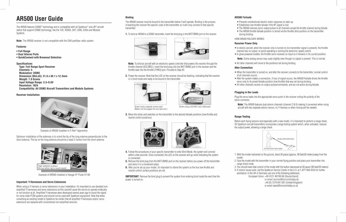
Binding
The AR500 receiver must be bound to the transmitter before it will operate. Binding is the process of teaching the receiver the specific code of the transmitter so it will only connect to that specific transmitter.
1. To bind an AR500 to a DSM2 transmitter, insert the bind plug in the BATT/BIND port on the receiver.
Note: To bind an aircraft with an electronic speed controller that powers the receiver through the throttle channel (ESC/BEC), insert the bind plug into the BATT/BIND port in the receiver and the throttle lead into the throttle (THRO) port. Proceed to Step #2.
2. Power the receiver. Note that the LED on the receiver should be flashing, indicating that the receiver is in bind mode and ready to be bound to the transmitter.
3. Move the sticks and switches on the transmitter to the desired failsafe positions (low throttle and neutral control positions).
4. Follow the procedures of your specific transmitter to enter Bind Mode, the system will connect within a few seconds. Once connected, the LED on the receiver will go solid indicating the system is connected.
5. Remove the bind plug from the BATT/BIND port on the receiver before you power off the transmitter and store it in a convenient place.
6. After you’ve set up your model, it’s important to rebind the system so the true low throttle and neutral control surface positions are set.
IMPORTANT: Remove the bind plug to prevent the system from entering bind mode the next time the power is turned on.
AR500 User GuideThe AR500 features DSM2™ technology and is compatible with all Spektrum™ and JR® aircraft radios that support DSM2 technology, like the 12X, X9303, DX7, DX6i, DX5e and Module Systems.
Note: The AR500 receiver is not compatible with the DX6 parkflyer radio system.
Features
• Full Range• Dual Aileron Ports• QuickConnect with Brownout Detection
Specifications: Type: Full Range Sport Receiver Channels: 5 Modulation: DSM2 Dimension (WxLxH): 21.6 x 30.1 x 12.3mm Weight: 7.0 Grams Input Voltage Range: 3.5–9.6V Resolution: 1024 Compatibility: All DSM2 Aircraft Transmitters and Module Systems
Receiver Installation
Example of AR500 installed in E-flite® Apprentice
Optimum installation of the antennas is to orient the tip of the long antenna perpendicular to the short antenna. The tip on the long antenna should be a least 2 inches from the short antenna.
Example of AR500 installed in Hangar 9® Pulse XT 60
Important: Y-Harnesses and Servo Extensions
When using a Y-harness or servo extensions in your installation, it’s important to use standard non- amplified Y-harnesses and servo extensions as this can/will cause the servos to operate erratically or not function at all. Amplified Y-harnesses were developed several years ago to boost the signal for some older PCM systems and should not be used with Spektrum equipment. Note that when converting an existing model to Spektrum be certain that all amplfied Y-harnesses and/or servo extensions are replaced with conventional non-amplified versions.
Tape antenna in place. Do not allow tip to touch metal.
AR500 Failsafe
�� •�Prevents�unintentional�electric�motor�response�on�start-up.� •�Establishes�low-throttle�failsafe�if�the�RF�signal�is�lost.� •��The AR500 removes servo output pulses to all channels except the throttle channel during failsafe.� •��The�AR500�throttle�failsafe�position�is�stored�via�the�throttle�stick�position�on�the�transmitter�
during binding.
HOW AR500 FAILSAFE WORKS
Receiver Power Only
•��In�electric�aircraft,�when�the�receiver�only�is�turned�on�(no�transmitter�signal�is�present),�the�throttle�channel has no output, to avoid operating or arming the electronic speed control.
•��In�glow-powered�models,�the�throttle�servo�receives�no�input�so�it�remains�in�its�current�position.�
Note: Some analog servos may coast slightly even though no signal is present. This is normal.
•�All�other�channels�will�move�to�the�positions�set�during�binding.
After Connection
•��When�the�transmitter�is�turned�on,�and�after�the�receiver�connects�to�the�transmitter,�normal�control�of all channels occurs.
•��After�the�system�makes�a�connection,�if�loss�of�signal�occurs,�the�AR500�Failsafe�drives�the�throttle�servo only to its preset failsafe position (low throttle) that was set during binding.
•�All�other�channels�receive�no�output�pulses/commands,�and�are�not�active�during�failsafe.�
Plugging in the Leads
Plug the servo leads into the appropriate servo ports in the receiver noting the polarity of the servo connector.
Note: The AR500 features dual aileron channels (channel 2 & 6) making it convenient when using aircraft with two separate aileron servos, no Y-harness or when mixing will be needed.
Range Testing
Before each flying session and especially with a new model, it is important to perform a range check. All Spektrum aircraft transmitters incorporate a range testing system which, when activated, reduces the output power, allowing a range check.
1. With the model restrained on the ground, stand 30 paces (approx. 90 feet/28 meters) away from the model.
2. Face the model with the transmitter in your normal flying position and place your transmitter into range check mode.
3. You should have total control of the model with the button depressed at 30 paces (90 feet/28 meters). 4. If control issues exist, call the Spektrum Service Center in the U.S. at 1-877-504-0233 for further
assistance. In the UK or Germany use one of the following addresses. European Union: +49 4121 46199 66 (Deutschland) or email [email protected]
+44 (0) 1279 641 097 (United Kingdom) or email [email protected]
Shown using a ESC/BEC and a flight pack.Shown using a separate receiver pack. (Battery can be plugged into any open port.)
Pull and hold the Trainer Switch
30 paces (90 feet/28 meters)

Receiver Power System Requirements
Inadequate power systems that are unable to provide the necessary minimum voltage to the receiver during flight have become the number one cause of in-flight failures. Some of the power system components that affect the ability to properly deliver adequate power include:
•�Receiver�battery�pack�(number�of�cells,�capacity,�cell�type,�state�of�charge)�
•�The�ESC’s�capability�to�deliver�current�to�the�receiver�in�electric�aircraft
•�The�switch�harness,�battery�leads,�servo�leads,�regulators�etc.
The AR500 has a minimum operational voltage of 3.5 volts; it is highly recommended the power system be tested per the guidelines below.
Recommended Power System Test Guidelines
If a questionable power system is being used (e.g. small or old battery, ESC that may not have a BEC that will support high current draw, etc.), it is recommended that a voltmeter be used to perform the following tests.
Note: The Hangar 9 Digital Servo & Rx Current Meter (HAN172) or the Spektrum Flight Log (SPM9540) are the perfect tools to perform the test below.
Plug the voltmeter into an open channel port in the receiver and with the system on, load the control surfaces (apply pressure with your hand) while monitoring the voltage at the receiver. The voltage should remain above 4.8 volts even when all servos are heavily loaded.
Note: The latest generations of Nickel-Metal Hydride batteries incorporate a new chemistry mandated to be more environmentally friendly. These batteries when charged with peak detection fast chargers have tendencies to false peak (not fully charge) repeatedly. These include all brands of NiMH batteries. If using NiMH packs, be especially cautious when charging, making absolutely sure that the battery is fully charged. It is recommended to use a charger that can display total charge capacity. Note the number of mAh put into a discharged pack to verify it has been charged to full capacity.
QuickConnect™ With Brownout Detection
Your AR500 features QuickConnect with Brownout Detection. •��Should�an�interruption�of�power�occur�(brownout),�the�system�will�reconnect�immediately�when�
power is restored (QuickConnect). •�The�LED�on�the�receiver�will�flash�slowly�indicating�a�power�interruption�(brownout)�has�occurred.�•��Brownouts�can�be�caused�by�an�inadequate�power�supply�(weak�battery�or�regulator),�a�loose�
connector, a bad switch, an inadequate BEC when using an Electronic speed controller, etc. •��Brownouts�occur�when�the�receiver�voltage�drops�below�3.5�volts�thus�interrupting�control�as�the�
servos and receiver require a minimum of 3.5 volts to operate. How QuickConnect With Brownout Detection Works
•�When�the�receiver�voltage�drops�below�3.5�volts�the�system�drops�out�(ceases�to�operate).�•��When�power�is�restored�the�receiver�immediately�attempts�to�reconnect�to�the�last�two�frequencies�
that it was connected to. •��If�the�two�frequencies�are�present�(the�transmitter�was�left�on)�the�system�reconnects�typically�within�
one second.
QuickConnect with Brownout Detection is designed to allow you to fly safely through most short duration power interruptions, however, the root cause of these interruptions must be corrected before the next flight to prevent a crash.
Note: If a brownout occurs in flight it is vital that the cause of the brownout be determined and corrected.
Antenna Polarization
For optimum RF link performance it’s important that the antennas be mounted in an orientation that allows for the best possible signal reception when the aircraft is in all possible attitudes and positions. This is known as antenna polarization. The antennas should be oriented perpendicular to each other; typically one vertical and one horizontal (see Receiver Installation). The long antenna can be mounted in a position perpendicular at least 2 inches away from the short antenna using tape.
14226
Tips on Using Spektrum 2.4GHz
ModelMatch™ Some Spektrum and JR transmitters offer a patent-pending feature called ModelMatch. ModelMatch prevents the possibility of operating a model using the wrong model memory, potentially preventing a crash. With ModelMatch each model memory has its own unique code (GUID) and during the binding process the code is programmed into the receiver. Later, when the system is turned on, the receiver will only connect to the transmitter if the corresponding model memory is programmed on screen.
Note: If at any time you turn on the system and it fails to connect, check to be sure the correct model memory is selected in the transmitter. Please note that the DX5e and Aircraft Modules do not have ModelMatch.
While your DSM equipped 2.4GHz system is intuitive to operate, functioning nearly identically to 72MHz systems, following are a few common questions from customers:
1. Q: Which do I turn on first, the transmitter or the receiver? A: If the receiver is turned off first —all servos except for the throttle will be driven to their preset
failsafe positions set during binding. At this time the throttle channel doesn’t output a pulse position preventing the arming of electronic speed controllers or in the case of an engine powered aircraft the throttle servo remains in its current position. When the transmitter is then turned on the transmitter scans the 2.4GHz band and acquires two open channels. Then the receiver that was previously bound to the transmitter scans the band and finds the GUID (Globally Unique Identifier code) stored during binding. The system then connects and operates normally. If the transmitter is turned on first—the transmitter scans the 2.4GHz band and acquires two open channels. When the receiver is then turned on for a short period (the time it takes to connect) all servos except for the throttle are driven to their preset failsafe positions while the throttle has no output pulse. The receiver scans the 2.4GHz band looking for the previously stored GUID and when it locates the specific GUID code and confirms uncorrupted repeatable packet information, the system connects and normal operation takes place. Typically this takes 2 to 6 seconds.
2. Q: Sometimes the system takes longer to connect and sometimes it doesn’t connect at all?
A: In order for the system to connect (after the receiver is bound) the receiver must receive a large number of consecutive uninterrupted perfect packets from the transmitter in order to connect. This process is purposely critical of the environment ensuring that it’s safe to fly when the system does connect. If the transmitter is too close to the receiver (less that 4 ft.) or if the transmitter is located near metal objects (metal TX case, the bed of a truck, the top of a metal work bench, etc.) connection will take longer and in some cases connection will not occur as the system is receiving reflected 2.4GHz energy from itself and is interpreting this as unfriendly noise. Moving the system away from metal objects or moving the transmitter away from the receiver and powering the system again will cause a connection to occur. This only happens during the initial connection. Once connected the system is locked in and should a loss of signal occur (failsafe) the system connects immediately (4ms) when signal is regained.
3. Q: I’ve heard that the DSM system is less tolerant of low voltage. Is this correct? A: All DSM receivers have an operational voltage range of 3.5 to 9 volts. With most systems this is
not a problem as in fact most servos cease to operate at around 3.8 volts. When using multiple high-current draw servos with a single or inadequate battery/ power source, heavy momentary loads can cause the voltage to dip below this 3.5-volt threshold thus causing the entire system (servos and receiver) to brown out. When the voltage drops below the low voltage threshold (3.5 volts), the DSM receiver must reboot (go through the startup process of scanning the band and finding the transmitter) and this can take several seconds. Please read the receiver power requirement section as this explains how to test for and prevent this occurrence.
4. Q: Sometimes my receiver loses its bind and won’t connect requiring rebinding. What happens if the bind is lost in flight?
A: The receiver will never lose its bind unless it’s instructed to. It’s important to understand that during the binding process the receiver not only learns the GUID (code) of the transmitter but the transmitter learns and stores the type of receiver that it’s bound to. If the transmitter is placed into bind mode, the transmitter looks for the binding protocol signal from a receiver. If no signal is present, the transmitter no longer has the correct information to connect to a specific receiver and in essence the transmitter has been “unbound” from the receiver. We’ve had several DX7 customers that use transmitter stands or trays that unknowingly depress the bind button and the system is then turned on losing the necessary information to allow the connection to take place. We’ve also had DX7 customers that didn’t fully understand the range test process and pushed the bind button before turning on the transmitter also causing the system to “lose its bind.”
FCC InformationThis device complies with part 15 of the FCC rules. Operation is subject to the following two conditions: (1) This device may not cause harmful interference, and (2) this device must accept any interference received, including interference that may cause undesired operation.
Caution: Changes or modifications not expressly approved by the party responsible for compliance could void the user’s authority to operate the equipment.This product contains a radio transmitter with wireless technology which has been tested and found to be compliant with the applicable regulations governing a radio transmitter in the 2.400GHz to 2.4835GHz frequency range.The associated regulatory agencies of the following countries recognize the noted certifications for this product as authorized for sale and use:
Declaration of Conformity(in accordance with ISO/IEC 17050-1)
No. HH20080903
Product(s): AR500 ReceiverItem Number(s): SPMAR500
The object of declaration described above is in conformity with the requirements of the specifica-tions listed below, following the provisions of the European R&TTE directive 1999/5/EC:
EN 301 489-1, 301 489-17 General EMC requirements for Radio equipment
Signed for and on behalf of: Horizon Hobby, Inc. Champaign, IL USA Sept. 03, 2008
Steven A. Hall Vice President International Operations and Risk Management Horizon Hobby, Inc.


![[XLS]sdoig/knight/NSF Awards in MA.xlsx · Web view2050000 399999 87004 33555 195574 155990 25000 404924 308230 1300000 67887 600000 467000 400183 393681 99999 1011712 867040 524999](https://static.fdocuments.us/doc/165x107/5aef09f37f8b9ac2468c27fe/xls-sdoigknightnsf-awards-in-maxlsxweb-view2050000-399999-87004-33555-195574.jpg)