DVS 204 front cover rev C - Extron...
52
DVS 204 Digital Video Scaler series DVS 204, DVS 204 D, DVS 204 12V, DVS 204 D 12V 68-605-01 Rev. C 01 05
-
Upload
truongkiet -
Category
Documents
-
view
214 -
download
0
Transcript of DVS 204 front cover rev C - Extron...

DVS 204Digital Video Scaler series
DVS 204, DVS 204 D, DVS 204 12V, DVS 204 D 12V
68-605-01 Rev. C01 05

This symbol is intended to alert the user of important operating and maintenance(servicing) instructions in the literature provided with the equipment.
This symbol is intended to alert the user of the presence of uninsulated dangerousvoltage within the product's enclosure that may present a risk of electric shock.
CautionRead Instructions • Read and understand all safety and operating instructions before using the
equipment.
Retain Instructions • The safety instructions should be kept for future reference.
Follow Warnings • Follow all warnings and instructions marked on the equipment or in the userinformation.
Avoid Attachments • Do not use tools or attachments that are not recommended by the equipmentmanufacturer because they may be hazardous.
WarningPower sources • This equipment should be operated only from the power source indicated on the
product. This equipment is intended to be used with a main power system with a grounded(neutral) conductor. The third (grounding) pin is a safety feature, do not attempt to bypass ordisable it.
Power disconnection • To remove power from the equipment safely, remove all power cords fromthe rear of the equipment, or the desktop power module (if detachable), or from the powersource receptacle (wall plug).
Power cord protection • Power cords should be routed so that they are not likely to be stepped on orpinched by items placed upon or against them.
Servicing • Refer all servicing to qualified service personnel. There are no user-serviceable partsinside. To prevent the risk of shock, do not attempt to service this equipment yourself becauseopening or removing covers may expose you to dangerous voltage or other hazards.
Slots and openings • If the equipment has slots or holes in the enclosure, these are provided toprevent overheating of sensitive components inside. These openings must never be blocked byother objects.
Lithium battery • There is a danger of explosion if battery is incorrectly replaced. Replace it onlywith the same or equivalent type recommended by the manufacturer. Dispose of used batteriesaccording to the manufacturer's instructions.
Ce symbole sert à avertir l’utilisateur que la documentation fournie avec le matérielcontient des instructions importantes concernant l’exploitation et la maintenance(réparation).
Ce symbole sert à avertir l’utilisateur de la présence dans le boîtier de l’appareil de tensions dangereuses non isolées posant des risques d’électrocution.
AttentionLire les instructions• Prendre connaissance de toutes les consignes de sécurité et d’exploitation avant
d’utiliser le matériel.
Conserver les instructions• Ranger les consignes de sécurité afin de pouvoir les consulter à l’avenir.
Respecter les avertissements • Observer tous les avertissements et consignes marqués sur le matériel ouprésentés dans la documentation utilisateur.
Eviter les pièces de fixation • Ne pas utiliser de pièces de fixation ni d’outils non recommandés par lefabricant du matériel car cela risquerait de poser certains dangers.
AvertissementAlimentations• Ne faire fonctionner ce matériel qu’avec la source d’alimentation indiquée sur
l’appareil. Ce matériel doit être utilisé avec une alimentation principale comportant un fil deterre (neutre). Le troisième contact (de mise à la terre) constitue un dispositif de sécurité :n’essayez pas de la contourner ni de la désactiver.
Déconnexion de l’alimentation• Pour mettre le matériel hors tension sans danger, déconnectez tousles cordons d’alimentation de l’arrière de l’appareil ou du module d’alimentation de bureau (s’ilest amovible) ou encore de la prise secteur.
Protection du cordon d’alimentation • Acheminer les cordons d’alimentation de manière à ce quepersonne ne risque de marcher dessus et à ce qu’ils ne soient pas écrasés ou pincés par desobjets.
Réparation-maintenance • Faire exécuter toutes les interventions de réparation-maintenance par untechnicien qualifié. Aucun des éléments internes ne peut être réparé par l’utilisateur. Afind’éviter tout danger d’électrocution, l’utilisateur ne doit pas essayer de procéder lui-même à cesopérations car l’ouverture ou le retrait des couvercles risquent de l’exposer à de hautes tensionset autres dangers.
Fentes et orifices • Si le boîtier de l’appareil comporte des fentes ou des orifices, ceux-ci servent àempêcher les composants internes sensibles de surchauffer. Ces ouvertures ne doivent jamaisêtre bloquées par des objets.
Lithium Batterie • Il a danger d'explosion s'll y a remplacment incorrect de la batterie. Remplaceruniquement avec une batterie du meme type ou d'un ype equivalent recommande par leconstructeur. Mettre au reut les batteries usagees conformement aux instructions du fabricant.
Safety Instructions • English
Consignes de Sécurité • Français
Sicherheitsanleitungen • Deutsch
Este símbolo se utiliza para advertir al usuario sobre instrucciones importantes deoperación y mantenimiento (o cambio de partes) que se desean destacar en elcontenido de la documentación suministrada con los equipos.
Este símbolo se utiliza para advertir al usuario sobre la presencia de elementos convoltaje peligroso sin protección aislante, que puedan encontrarse dentro de la cajao alojamiento del producto, y que puedan representar riesgo de electrocución.
PrecaucionLeer las instrucciones • Leer y analizar todas las instrucciones de operación y seguridad, antes de usar
el equipo.
Conservar las instrucciones • Conservar las instrucciones de seguridad para futura consulta.
Obedecer las advertencias • Todas las advertencias e instrucciones marcadas en el equipo o en ladocumentación del usuario, deben ser obedecidas.
Evitar el uso de accesorios • No usar herramientas o accesorios que no sean especificamenterecomendados por el fabricante, ya que podrian implicar riesgos.
AdvertenciaAlimentación eléctrica • Este equipo debe conectarse únicamente a la fuente/tipo de alimentación
eléctrica indicada en el mismo. La alimentación eléctrica de este equipo debe provenir de unsistema de distribución general con conductor neutro a tierra. La tercera pata (puesta a tierra) esuna medida de seguridad, no puentearia ni eliminaria.
Desconexión de alimentación eléctrica • Para desconectar con seguridad la acometida dealimentación eléctrica al equipo, desenchufar todos los cables de alimentación en el panel traserodel equipo, o desenchufar el módulo de alimentación (si fuera independiente), o desenchufar elcable del receptáculo de la pared.
Protección del cables de alimentación • Los cables de alimentación eléctrica se deben instalar enlugares donde no sean pisados ni apretados por objetos que se puedan apoyar sobre ellos.
Reparaciones/mantenimiento • Solicitar siempre los servicios técnicos de personal calificado. En elinterior no hay partes a las que el usuario deba acceder. Para evitar riesgo de electrocución, nointentar personalmente la reparación/mantenimiento de este equipo, ya que al abrir o extraer lastapas puede quedar expuesto a voltajes peligrosos u otros riesgos.
Ranuras y aberturas • Si el equipo posee ranuras o orificios en su caja/alojamiento, es para evitar elsobrecalientamiento de componentes internos sensibles. Estas aberturas nunca se deben obstruircon otros objetos.
Batería de litio • Existe riesgo de explosión si esta batería se coloca en la posición incorrecta. Cambiaresta batería únicamente con el mismo tipo (o su equivalente) recomendado por el fabricante.Desachar las baterías usadas siguiendo las instrucciones del fabricante.
Instrucciones de seguridad • Español
Precautions
Dieses Symbol soll dem Benutzer in der im Lieferumfang enthaltenenDokumentation besonders wichtige Hinweise zur Bedienung und Wartung(Instandhaltung) geben.
Dieses Symbol soll den Benutzer darauf aufmerksam machen, daß im Inneren desGehäuses dieses Produktes gefährliche Spannungen, die nicht isoliert sind unddie einen elektrischen Schock verursachen können, herrschen.
AchtungLesen der Anleitungen • Bevor Sie das Gerät zum ersten Mal verwenden, sollten Sie alle Sicherheits-und
Bedienungsanleitungen genau durchlesen und verstehen.
Aufbewahren der Anleitungen • Die Hinweise zur elektrischen Sicherheit des Produktes sollten Sieaufbewahren, damit Sie im Bedarfsfall darauf zurückgreifen können.
Befolgen der Warnhinweise • Befolgen Sie alle Warnhinweise und Anleitungen auf dem Gerät oder inder Benutzerdokumentation.
Keine Zusatzgeräte • Verwenden Sie keine Werkzeuge oder Zusatzgeräte, die nicht ausdrücklich vomHersteller empfohlen wurden, da diese eine Gefahrenquelle darstellen können.
VorsichtStromquellen • Dieses Gerät sollte nur über die auf dem Produkt angegebene Stromquelle betrieben
werden. Dieses Gerät wurde für eine Verwendung mit einer Hauptstromleitung mit einemgeerdeten (neutralen) Leiter konzipiert. Der dritte Kontakt ist für einen Erdanschluß, und stellteine Sicherheitsfunktion dar. Diese sollte nicht umgangen oder außer Betrieb gesetzt werden.
Stromunterbrechung • Um das Gerät auf sichere Weise vom Netz zu trennen, sollten Sie alleNetzkabel aus der Rückseite des Gerätes, aus der externen Stomversorgung (falls dies möglichist) oder aus der Wandsteckdose ziehen.
Schutz des Netzkabels • Netzkabel sollten stets so verlegt werden, daß sie nicht im Weg liegen undniemand darauf treten kann oder Objekte darauf- oder unmittelbar dagegengestellt werdenkönnen.
Wartung • Alle Wartungsmaßnahmen sollten nur von qualifiziertem Servicepersonal durchgeführtwerden. Die internen Komponenten des Gerätes sind wartungsfrei. Zur Vermeidung eineselektrischen Schocks versuchen Sie in keinem Fall, dieses Gerät selbst öffnen, da beim Entfernender Abdeckungen die Gefahr eines elektrischen Schlags und/oder andere Gefahren bestehen.
Schlitze und Öffnungen • Wenn das Gerät Schlitze oder Löcher im Gehäuse aufweist, dienen diesezur Vermeidung einer Überhitzung der empfindlichen Teile im Inneren. Diese Öffnungen dürfenniemals von anderen Objekten blockiert werden.
Litium-Batterie • Explosionsgefahr, falls die Batterie nicht richtig ersetzt wird. Ersetzen Sieverbrauchte Batterien nur durch den gleichen oder einen vergleichbaren Batterietyp, der auchvom Hersteller empfohlen wird. Entsorgen Sie verbrauchte Batterien bitte gemäß denHerstelleranweisungen.

Quick Start — DVS 204
InstallationStep 1Refer to the application examples at the end of thispage. Turn off power to the scaler and input andoutput devices, and remove power cords fromthem.
Step 2Install the four rubber feet on the bottom of theDVS 204 scaler, or mount the scaler in a rack.
Step 3Attach input devices to the scaler.
Rear panel video inputsInput 1: Composite video
Input 2: Composite/S-video/Component
Input 3: S-video
Input 4: RGB pass-through/RGBS/RGBcS
SDI input
Attach an SDI source to this BNC (204 Dmodel only).
Step 4Attach output devices to the scaler.
Rear panel video outputsOutput BNC connectors
Output 15-pin HD connector
You can connect both outputs simultaneouslyto two different displays. The sync format isthe same for both outputs.
Laptop Computer
DVD Player
INPUTS
R-Y
50/60 Hz
1
2 3 4
Y/VID
B-Y/C
H
R/R-Y
V
G/Y
S
B/B-Y
VIDEO REMOTE
RGB/R-Y,Y,B-Y
RGBPASS - THRU
RGBcvSS-VIDEO
SDIOUTPUTS100-240V 0.3A
DVS 204 D
VCR
Document Camera
RS-232 Control
LCD Projector
Plasma Display
Application examples
1
VIDEO
R-Y
2
Y/VID
B-Y/C
R-Y
2
Y/VID
B-Y/C
Composite Video Component Video (R-Y, Y, B-Y)S-video (Y/C)
R-Y
2
Y/VID
B-Y/C
3
S-VIDEO
4
RGBPASS - THRU/
RGBS/RGBcvS
SDI
H
R/R-Y
V
G/Y
S
B/B-Y
OUTPUTS
H
R/R-Y
V
G/Y
S
B/B-Y
OUTPUTS
H
R/R-Y
V
G/Y
S
B/B-Y
OUTPUTS
H
R/R-Y
V
G/Y
S
B/B-Y
OUTPUTS
Component Video (R-Y, Y, B-Y)
RGBHV RGBS
RGsB
Step 5Plug the DVS 204, and input and output devicesinto a grounded AC source, and turn on the inputand output devices.
Step 6Use the LCD menu screens or RS-232programming to configure the scaler. See chaptertwo for installation and operation procedures, andsee chapter three for programming information.
RGB/R-Y,Y,B-Y
INPUTS
R-Y
POWER12V 1.5A DC
1
2 3 4
Y/VID
B-Y/C
H
R/R-Y
V
G/Y
S
B/B-Y
VIDEO REMOTE
RGB/R-Y,Y,B-Y
RGBPASS - THRU
RGBS/RGBcvSS-VIDEO
SDIOUTPUTS
Laptop Computer
DVD Player
Power Supply
DVS 204 D 12V
VCR
Document Camera
RS-232 Control
Monitor
LCD Projector

Quick Start — DVS 204, cont’d

iDVS 204 • Table of Contents
Table of Contents
Chapter 1 • Introduction ...................................................................................................... 1-1
About this Manual ............................................................................................................ 1-2
About the DVS 204 ........................................................................................................... 1-2What is the DVS 204? ....................................................................................................... 1-2Controlling the DVS 204 digital video scaler ................................................................ 1-2
Features and Options ...................................................................................................... 1-2Features .............................................................................................................................. 1-2Options and accessories ................................................................................................... 1-3
Chapter 2 • Installation and Operation ...................................................................... 2-1
Mounting the Scaler ........................................................................................................ 2-2Tabletop/desktop placement ........................................................................................... 2-2Rack mounting .................................................................................................................. 2-2Application diagram ........................................................................................................ 2-3
Rear Panel Features .......................................................................................................... 2-4
Front Panel Features ........................................................................................................ 2-7Input selection buttons .................................................................................................... 2-7Picture adjustment buttons ............................................................................................. 2-7Menu button ..................................................................................................................... 2-8Next button ....................................................................................................................... 2-8LCD menu display and controls ...................................................................................... 2-8
Optimizing the System for a DVD ........................................................................... 2-8Setting up a DVD source .................................................................................................. 2-8
Menus, Configuration, and Adjustments ............................................................ 2-9Moving through menus by using front panel controls ............................................... 2-9Menu overview ................................................................................................................. 2-9Input Configuration ....................................................................................................... 2-10
Input 2 Video Type............................................................................................................. 2-11Input 4 Video Type............................................................................................................. 2-11SDI Input (SDI IN) ............................................................................................................... 2-11
Output Configuration .................................................................................................... 2-11Resolution and refresh rates ............................................................................................ 2-12Output Signal ..................................................................................................................... 2-12Sync Polarity ...................................................................................................................... 2-12H Format ............................................................................................................................ 2-13
Blanking Configuration ................................................................................................. 2-13Top and bottom blanking ................................................................................................. 2-13
Memory Preset ................................................................................................................ 2-13Save (SAVE) memory preset ............................................................................................. 2-14Clear (CLR) memory preset ............................................................................................... 2-14Recalling a preset .............................................................................................................. 2-15
Advanced Configuration ................................................................................................ 2-15Detail control ..................................................................................................................... 2-15Filter mode ........................................................................................................................ 2-15Blue mode .......................................................................................................................... 2-16
ii DVS 204 • Table of Contents
Table of Contents, cont’d
Autoswitch (Autosw) mode .............................................................................................. 2-16Enhanced (Enh) mode ....................................................................................................... 2-162:2 Pulldown detection (PAL Film mode detect) submenu ............................................. 2-16RGB delay (Triple Action Switching) .................................................................................. 2-16
Exit Menu ........................................................................................................................ 2-17
Image Adjustments ........................................................................................................ 2-17Color, tint, brightness, contrast, centering, sizing ..................................................... 2-17
Input Reset .......................................................................................................................... 2-18
System Reset ...................................................................................................................... 2-18
Front Panel Security Lockout (Executive Mode) ............................................ 2-19
IR 901 Infrared Remote Control .............................................................................. 2-20Aspect ratio presets ........................................................................................................ 2-20Freezing an input ........................................................................................................... 2-20Selecting an input .......................................................................................................... 2-20Size and center ............................................................................................................... 2-20Image adjustments ......................................................................................................... 2-20
Troubleshooting ............................................................................................................... 2-21Operating problems ....................................................................................................... 2-21
Chapter 3 • Serial Communication ................................................................................ 3-1
RS-232 Programmer’s Guide ........................................................................................ 3-2Host-to-scaler communications ....................................................................................... 3-2
Scaler-initiated messages ................................................................................................... 3-2Error responses ................................................................................................................... 3-2Using the command/response tables ................................................................................. 3-3Command/response table for SIS commands ..................................................................... 3-4Command/response table for special function SIS commands .......................................... 3-7
Control Software for Windows ................................................................................. 3-8Installing the software ..................................................................................................... 3-8Using the control program .............................................................................................. 3-8Using the help program ................................................................................................... 3-9
Appendix A • Appendix ........................................................................................................ A-1
Specifications ..................................................................................................................... A-2
Part Numbers and Accessories ................................................................................. A-4Included parts .................................................................................................................. A-4Accessories ........................................................................................................................ A-4
Firmware Upgrade Installation ................................................................................. A-5
Serial Digital Interface (SDI) Card Installation ............................................... A-7
68-605-01 Rev. C01 05
All trademarks mentioned in this manual are the properties of their respective owners.

DVS 204
1Chapter One
Introduction
About this Manual
About the DVS 204
Features and Options

DVS 204 • Introduction1-2
Introduction
About this ManualThis manual discusses how to install, configure, and operate the Extron DVS 204digital video scaler and how to operate the optional IR 901 infrared remotecontrol (part #70-152-01).
Throughout this manual the terms “DVS”, “digital video scaler”, and “scaler”are used interchangeably to refer to the same product.
About the DVS 204
What is the DVS 204?The DVS is a series of high performance digital video scalers that offers 56output rates, including HDTV, and provides scaling solutions for boardrooms,conference rooms, and home theaters, as well as rental and staging applications.
The scalers come in four models, two of which offer a serial digital interface (SDI)input connector: DVS 204 (no SDI), DVS 204 D (SDI), DVS 204 12V (12 voltexternal power supply, no SDI), and DVS 204 D 12V (12 volt external powersupply, SDI).
To enable superior scaling performance, the DVS 204 features several of Extron’spatented and patent-pending technologies, including Dynamic MotionInterpolation (DMI™) technology, and 3:2 and 2:2 pulldown detection. DMI isan advanced motion detection and compensation method that enables imageenhancement with no loss of image fidelity.
The DVS 204 scales composite video, S-video, and component video up tocomputer-video (RGBHV/RGBS/RGsB) or HD component, which can be outputto two display devices via individually buffered BNC and 15-pin HD connectors.
Controlling the DVS 204 digital video scalerThe DVS 204 can be controlled using one or more of the following methods:
• The front panel controls.
• A computer, a touch screen panel, or any other device that can send andreceive the serial communications through the RS-232 port. Extron’sSimple Instruction Set (SIS™) is a set of simple keystroke commands thatcan be used with any such devices, and Extron’s control software forWindows provides a graphical interface for controlling the scaler from acomputer.
• The optional IR 901 remote control, which has most of the front panel controls.
Features and OptionsFeatures
Four video inputs• Input 1 — One BNC connector on the rear panel accepts composite video.• Input 2 — Three BNC connectors on the rear panel accept composite,
component, or S-video.• Inputs 3 — One 4-pin DIN connector accepts an S-video signal.• Input 4 — One 15-pin HD connector accepts an RGB pass-through
(RGBHV, RGBS, RGsB), RGBS, or RGBcvS video signal.
SDI video input (optional) — One BNC connector on the rear panel accepts SDIvideo.

1-3DVS 204 • Introduction
Buffered video outputs — Six rear-panel BNC connectors and one VGA-type15-pin HD connector provide connections for RGB output. Both outputs(the BNCs or the 15-pin HD connector) are active at all times forsimultaneous output.
Three ways to control the scaler — The scaler’s front panel, a computer or otherRS-232 control device, or the optional IR 901 remote control can all be usedto control the scaler.
Scaled outputs — The DVS 204 offers 59 different output rates.
RS-232 configuration — The DVS 204 can be configured by using the Extroncontrol software for Windows, or by using a third party control system.
Accu-RATE Frame Lock™ — The Extron Accu-RATE Frame Lock™ eliminatesartifacts from scaled motion video by eliminating frame rate conversion. Itlocks the output frame rate to the input frame rate of the active input. Theresult is a switching system that eliminates image tears and other artifactsfrom motion video.
Dynamic Motion Interpolation™ (DMI™) — This video processing technique isan advanced motion prediction and compensation method that treatsmotion content and still content with different algorithms to yield highfidelity images.
3:2 pulldown detection for NTSC and 2:2 film detection for PAL video sources— These advanced film mode processing features help maximize imagedetail and sharpness for video sources that originated from film. Whenfilm is converted to NTSC video, the film frame rate has to be matched tothe video frame rate in a process called 3:2 pulldown. Jaggies and otherimage artifacts can result if conventional deinterlacing techniques are usedon film-source video. The DVS 204’s advanced film mode processingrecognizes signals that originated from film. The DVS 204 then appliesvideo processing algorithms that optimize the conversion of video that wasmade with the 3:2 pulldown process. This results in richly detailed imageswith sharply defined lines. A similar process is used for PAL film-sourcevideo.
Versatile mounting options — The DVS 204 is 1U high, and a half rack wide. Itis rack mountable, or it can be placed on a table or other furniture. Rubberfeet are included.
Options and accessoriesThe DVS 204’s optional equipment includes:
• IR 901 remote control — Extron’s IR 901 (part #70-152-01) is an infraredremote control which replicates all of the front panel controls of theDVS 204 except the Menu and Next buttons.
• SDI input card — Serial digital interface (SDI) input can be added to theDVS 204 model by the installation of an SDI input card (part #70-168-01).
• Rack shelf mounting kit — The 1U high, half rack width DVS 204 can be rackmounted using the rack shelf mounting kit (part #60-190-01).

Introduction, cont’d
DVS 204 • Introduction1-4

DVS 204
2Chapter Two
Installation and Operation
Mounting the Scaler
Rear Panel Features
Front Panel Features
Optimizing the System for a DVD
Menus, Configuration, and Adjustments
Image Adjustments
Input Reset
System Reset
Front Panel Security Lockout (Executive Mode)
IR 901 Infrared Remote Control
Troubleshooting

Installation and Operation
DVS 204 • Installation and Operation2-2
Mounting the ScalerTabletop/desktop placement
For tabletop or desktop placement only, install the self-adhesive rubber feet/pads(provided) onto the four corners of the bottom of the enclosure.
Rack mounting1. If feet were installed on the bottom of the DVS 204, remove them.
2. Place the DVS 204 on one half of the 1U (one unit high, one unit wide)rack shelf (part #60-190-01). Align the front of the DVS 204 with thefront of the shelf, and align the threaded holes on the bottom of theDVS 204 with the holes in the rack shelf.
3. Attach the DVS to the rack shelf with the two provided 4-40 x 3/16"machine screws. Insert the screws from the underside of the shelf, andsecurely fasten them into diagonally-opposite corners.
Rack mounting the DVS 204
4. Attach the false front panel (provided with the rack shelf) to theunoccupied side of the rack (as shown above), or install a second half-rack-width device in that side by repeating steps 1–3.
5. Attach the rack shelf to the rack using four 10-32 x ¾" bolts (provided).Insert the bolts through #10 beveled washers, then through the holes inthe rack ears and rack, as shown above.
(2) 4-40 x 3/16" Screws
Use 2 mounting holes onopposite corners.
False front paneluses 2 front holes.
COMPOSITE
1
DVS 204
DIGITAL VIDEO SCALER
YUV
2
S-VIDEO
3
RGB
4
BRT/CONT
COL/TNT
SIZE
CENTERMENU
NEXT
ADJUST
IR

2-3DVS 204 • Installation and Operation
Application diagramThe diagram shown below is an example of a typical DVS 204 application withcable connections.
Application diagram example of the DVS 204
Document CameraVCR
Monitor
RS-232 Control
LCD Projector
Laptop ComputerDVD Player
DVS 204
INPUTS
R-Y
1
2
3Y
B-Y
/C
SDIH
R
V
G
S
B
VIDEO
REMOTE
RGB/R-Y,Y,B-Y
RGB
PASS-THRU/
RGBcS
OUTPUTS

Installation and Operation
DVS 204 • Installation and Operation2-4
Rear Panel FeaturesThe rear panels of the DVS 204 D and DVS 204 D 12V models, as shown below,contain all of the possible connectors available on the DVS 204 series of scalers(the DVS 204 and DVS 12V models do not come with an SDI input connector).
DVS 204 D rear panel connectors
DVS 204 D 12V rear panel power connector
The rear panel connectors of the 12V DC models are identical to those of theAC models, except for the 12 volt power input connector.
1 AC power connector — Plug a standard IEC power cord into thisconnector to connect the scaler to a 100 to 240 VAC, 50 Hz or 60 Hz powersource. The front panel control and input selection LEDs will light duringpower-up.
1a 12V DC power connector — Plug the included 12 V power supply into thisinput jack (DVS 204 12V and DVS 204 D 12V models only). The front panelcontrol and input selection LEDs will light during power-up.
2 Video input 1: Composite video — A composite video signal isinput through the female BNC connector.
3 Video input 2: Composite/S-video/Component — This input,consisting of 3 female BNC connectors, accepts composite video, S-video,and component video signals. Connect cables for the appropriate signaltype, as shown here.
R-Y
2
Y/VID
B-Y/C
R-Y
2
Y/VID
B-Y/C
Composite Video Component Video (R-Y, Y, B-Y)S-video (Y/C)
R-Y
2
Y/VID
B-Y/C
INPUTS
R-Y
50/60 Hz
1
2 3 4
Y/VID
B-Y/C
H
R/R-Y
V
G/Y
S
B/B-Y
VIDEO REMOTE
RGB/R-Y,Y,B-Y
RGBPASS - THRU/
RGBS/RGBcvSS-VIDEO
SDIOUTPUTS100-240V 0.3A
1
2
3
5
4 6 8
9
7
INPUTS
R-Y
POWER12V 1.5A DC
1
2 3 4
Y/VID
B-Y/C
H
R/R-Y
V
G/Y
S
B/B-Y
VIDEO REMOTE
RGB/R-Y,Y,B-Y
RGBPASS - THRU
RGBS/RGBcvSS-VIDEO
SDIOUTPUTS
1a
1
VIDEO

2-5DVS 204 • Installation and Operation
4 Video input 3: S-video — Connect an S-video signal to this 4-pinmini-DIN female connector.
5 SDI (serial digital interface) input connector — Connect an SDIsignal to this female BNC connector.
Only the DVS 204 D and DVS 204 D 12V models have an SDI connector.
6 Video input 4: RGB pass-through, RGBS, or RGBcvS —Connect an RGB pass-through (RGBHV, RGBS, RGsB), RGBS,or RGBcvS video signal to this 15-pin HD connector. Thepass-through signals are not scalable.
Equipment following the SCART interconnection standardmay be connected to the RGBcvS input cabling configuration.
7 RGB (RGBHV, RGBS, RGsB) or HD component (R-Y, Y, B-Y) video BNCoutput — Connect coaxial cables from a display device to these BNCs for ascaled or pass-through RGB or a scaled component video output. Theoutput can be scaled to 56 different output rates. The scaled inputs (1-3) areoutput, as shown below.
The default for the “H” BNC connector is always horizontal sync. See thefollowing section “RGB pass-through”, for the only exception to this rule.
H
R/R-Y
V
G/Y
S
B/B-Y
OUTPUTS
H
R/R-Y
V
G/Y
S
B/B-Y
OUTPUTS
H
R/R-Y
V
G/Y
S
B/B-Y
OUTPUTS
H
R/R-Y
V
G/Y
S
B/B-Y
OUTPUTS
Component Video (R-Y, Y, B-Y)
RGBHV* RGBS
RGsB
Outputs 7 and 8 are both buffered and can be connected simultaneouslyto two different displays. For RGB inputs, the output signal’s sync format isbased on the format of the incoming RGB signal. For all other types ofinputs, the user selects the output sync format. The sync format will be thesame for both outputs.
RGB pass-through — An RGB pass-through signal with composite sync(“RGB” is selected for input 4; see the Input Configuration section in thischapter) will always output composite sync through the “H” BNC outputconnector, as shown in the following illustration.
If both an RGB pass-through signal with composite sync and a scaled videoinput (1-3) are output as RGBS, the H Format must be set to “HV”(composite sync). This will cause the scaled video input to output compositesync on the same connector (the “H” BNC) as the pass-through signalinstead of the “S” BNC. See the H Format section in this chapter.
For scaled inputs on input 4 (RGBS or RGBcvS), the H Format will nothave to be set to “HV” since those inputs will be output like inputs 1-3, asshown in the previous connection diagram.
3
S-VIDEO
4
RGBPASS - THRU/
RGBS/RGBcvS
SDI

Installation and Operation, cont’d
DVS 204 • Installation and Operation2-6
S
R/R-Y
V
G/Y
H
B/B-Y
OUTPUTS
RGBS from RGBS pass-through input
8 RGB or HD component (R-Y, Y, B-Y) 15-pin HD video output — Connectan RGB video display or HD component video display to this connector.
9 Remote (RS-232/contact closure) 9-pin port — This connector provides fortwo-way RS-232 communication and contact closure control. See chapterthree, “Serial Communication”, for information on how to install and usethe control software and SIS commands.
The default protocol is 9600 baud, 1 stop bit, no parity, and no flow control.
The rear panel RS-232 9-pin D female connector has the following pinassignments:
Pin RS-232 function Description
1 Input #1 Contact closure2 Tx Transmit data3 Rx Receive data4 Input #2 Contact closure5 Gnd Signal ground6 Input #3 Contact closure7 Input #4 Contact closure8 – No connection9 Hardwired IR IR input
The Remote connector also provides a way to select an input using a remotecontact closure device. Contact closure control uses pins on the Remoteconnector that are not used by the RS-232 interface (see preceding table).
To select a different input number using a contact closure device,momentarily short the pin for the desired input number to logic ground(pin 5). To force one of the inputs to be always selected, leave the short tologic ground in place. The short overrides front panel input selections.

2-7DVS 204 • Installation and Operation
Front Panel FeaturesThe front panel buttons, controls, LCD, and infrared sensor of the DVS 204, asshown below, are found on all models of the DVS 204 scaler series. The LEDsabove each input button will light green and the LEDs above/below each picturecontrol button will light amber when the button is pressed.
1
DVS 204DIGITAL VIDEO SCALER
2 3 4
BRT/CONT
COL/TNT
SIZE
CENTER MENU
NEXT
ADJUST
IR
1 32 4
7
5
6
8 9 10 11
12
DVS 204 front panel
Input selection buttons1 Composite input button — This button selects composite video input
(Input 1).
2 Composite/YC/component input button — This button selects compositevideo, YC, or component video input (Input 2).
3 S-video input button — This button selects the S-video input (Input 3).
4 RGB pass-through/RGBS/RGBcvS input button — This button selects theRGB pass-through (RGBHV, RGBS, RGsB), RGBS (15 kHz), or RGBcvSinput (Input 4).
An SDI input signal can be assigned to any of the inputs (Inputs 1 through4).
Picture adjustment buttonsPressing these buttons successively will toggle between the different pictureadjustment functions and light the LEDs above and below each button.
These buttons have no effect on the RGB pass-through inputs (Input 4).
5 Color/Tint control button (Col/Tnt) — This button controls the color andtint adjustment on the display by using the Adjust horizontal and Adjustvertical adjustment knobs. The adjustment range of both color and tint is 0to 255. See the “Image Adjustments” section in this chapter.
The tint control is not available if the input is component video.
Brightness/Contrast control button (Brt/Cont) — This button controls thebrightness and contrast adjustment on the display by using the Adjusthorizontal and Adjust vertical adjustment knobs. The adjustment range ofboth brightness and tint is 0 to 255. See the “Image Adjustments” section inthis chapter.
6 Center control button — This button controls the centering adjustment onthe output display by using the Adjust horizontal and Adjust verticaladjustment knobs. The adjustment range of both horizontal and verticalcentering is 0 to +255. See the “Image Adjustments” section in this chapter.

Installation and Operation, cont’d
DVS 204 • Installation and Operation2-8
Size control button — This button controls the size adjustment on thedisplay by using the Adjust horizontal and Adjust vertical adjustmentknobs. See the “Image adjustments” section in this chapter.
Menu button7 Menu button — Use this button to enter and move through the main menu
system in the DVS 204. See the “Menus, Configuration, and Adjustments”section in this chapter for details.
Next button8 Next button — Use this button to step through the submenus in the
DVS 204 menu system. See the “Menus, Configuration, and Adjustments”section in this chapter for details.
LCD menu display and controls9 LCD — Displays configuration menus and status information. See the
“Menus, Configuration, and Adjustments” section in this chapter fordetails.
10 Adjust horizontal ( ) knob — In the menu system, rotate this knob toscroll through menu options and make adjustments.
11 Adjust vertical ( ) knob — In the menu system, rotate this knob to scrollthrough menu options and make adjustments.
12 Infrared sensor — This sensor is used to receive infrared (IR) signals fromthe IR-901 remote control. See the “IR 901 Infrared Remote Control” sectionin this chapter.
Optimizing the System for a DVDFor optimal performance, follow the steps in this section in order when settingup the DVS 204 for a DVD.
Setting up a DVD sourceTo get the best results when using a DVD as a video source, Extron recommendsthat the DVD player itself be setup to output an aspect ratio of 16:9 and not 4:3.Because all DVDs are mastered as 16:9, having them set up for anything else willcause the player to internally scale and compress the signal. This scaling/compression by the DVD player will defeat the advantage of having 3:2pulldown detection in the DVS 204.
All sizing adjustments to correct aspect ratio should be done using the DVS 204.
To change the output aspect ratio of most DVD players,
1. Enter the DVD player’s Setup or Action menu while the disc is stopped.
2. Select a 16:9 aspect ratio.

2-9DVS 204 • Installation and Operation
Menus, Configuration, and AdjustmentsScaler configuration and adjustments can be performed by using the Windows-based control program (see chapter three for details) or by using the front panelcontrols and the menus that are displayed on the DVS 204’s LCD screen. Thesemenus are used primarily when the scaler is first set up.
Moving through menus by using front panel controlsMenu button — Press the Menu button to activate menus and to scroll to the six
main menus.
Next button — Press the Next button to move between the submenus of aselected main menu. Pressing the Next button during input configurationcauses the current input’s number and format type to be displayed on theLCD
Adjust ( , ) knobs — In configuration mode, rotate the Adjust horizontal ( )knob and Adjust vertical ( ) knob to scroll through submenu options and tomake adjustment selections. Refer to the flowcharts in this chapter and tospecific sections for explanations on knob adjustments.
Image adjustment buttons: Col/Tnt, (color/tint) Brt/Cont (brightness/contrast),Size, and Center — When one of these buttons is pressed successively, thecorresponding image adjustment menu appears on the LCD screen.Adjustments can then be made by rotating the Adjust horizontal ( ) knobor the Adjust vertical ( ) knob. Settings and adjustments are stored innonvolatile memory.
Menu overviewThe default menus appear on the LCD when no adjustments are actively beingmade. They cycle between the screen showing the model of the scaler (DVS 204or DVS 204 D) and the screen that shows the active input’s number and videoformat, as shown below.
Poweron
EXTRONDVS204D
2 sec.
2 sec.
INPUT 1CMPOSITE
852 x480 @60 2 sec. 2 sec.
NOSIGNAL
2 sec.
* The No Signal default menu only occurs if there is no signal present at the currently selected input connector.
Default menus
From any menu or submenu, after ten seconds of inactivity the DVS 204will save all adjustment settings and time-out to the default menus.
The main menus are as shown in the following flowchart. Use the Menu key toscroll between them.
The No Signal default menu only occurs if there is no signal present at thecurrently selected input connector.

Installation and Operation, cont’d
DVS 204 • Installation and Operation2-10
Main menus
To return to the default screens, let the DVS 204 time-out for 10 seconds, orpress the Menu button until the Exit Menu menu appears, then press the Nextbutton.
Submenus are accessed from a main menu by pressing the Next button. Ifyou press the Menu button while a submenu is active, the next main menuwill become active. For example, the menu will change from the InputConfiguration menu or its submenus to the Output Configuration mainmenu.
Input ConfigurationThe following flowchart provides an overview of the Input Configurationsubmenus and the options for each setting.
EXTRONDVS204D
INPUTCONFIG
MENU
NEXTINPUT 2
COMPNENTINPUT 4RGBcvS
SDI IN* 1 2 3 <4>NEXT NEXT NEXT
Input 2 video types• Composite• S-video• Component (default)
Assign SDI to Input #• 1, 2, 3, 4, * (none)
Input 4 video types• RGB pass-through (default)• RGBS• RGBcvS NOTE The SDI input can be assigned
to any input. Once assigned to a specific input, only an SDI signal can be accepted on that input. SDI can be disabled by selecting the *.
NOTE Input 1 can only accept composite video. Input 3 can only accept S-video. Only Inputs 2 and 4 can be configured for different video types, although an SDI input can be assigned from any Input Configuration menu.
INPUTCONFIG
MENU
MENU
OUTPUTCONFIG
MENU
BLANKINGCONFIG
MENU
MEMORYPRESET
MENU
ADVANCEDCONFIG
MENUNEXT
MENU
EXITMENU
Poweron
EXTRONDVS204D
2 sec.
2 sec.
INPUT 1CMPOSITE
852 x480 @60 2 sec. 2 sec.
NOSIGNAL
2 sec.
* The No Signal default menu only occurs if there is no signal present at the currently selected input connector.

2-11DVS 204 • Installation and Operation
Input 1 can only input composite video, and Input 3 can only input S-video,no other video types are selectable for these inputs. Only Inputs 2 and 4offer selectable video types. From the Input Configuration menu, pressingthe Next key successively will display submenus with the input video typesfor Inputs 2 and 4. The SDI input (if any) can be assigned to any input fromthe Input Configuration submenus.
Input 2 Video TypeRotate either the Adjust horizontal ( ) knob or Adjust vertical ( ) knob while inthe Input 2 submenu to select the appropriate video format (composite, S-video,component) for Input 2. The default is component video.
Input 4 Video TypeRotate the Adjust horizontal ( ) knob while in the Input 4 submenu to select theappropriate video format (RGB pass-through, RGBS, RGBcvS) for Input 4. Thedefault is RGB pass-through.
SDI input (SDI IN)Rotate either the Adjust horizontal ( ) knob or Adjust vertical ( ) knob while inthe SDI Input submenu to select the input # for the SDI input. The SDI input canbe assigned to Inputs 1, 2, 3, 4, or none (*). The default is none.
After the SDI input is no longer assigned to an input, either because it hasbeen assigned to a new input or is set to none, the input reverts back to thelast video type that was assigned to it.
Output ConfigurationThe following flowchart provides an overview of the Output Configurationsubmenus and the options for each setting.
ExtronDVS204D
OUTPUTCONFIG
MENU
NEXT640 x
480 @ 60SIGNAL
RGBH SYNC V
NEG POSNEXT NEXT NEXT
INPUTCONFIG
MENU
Scaler output rates• See the scaler output table in this
chapter for available combinations of resolutions and refresh rates.
Default: 1024 x 768 @60 Hz
Output video types• RGB (default)• YUV• RGsB
Sync polarity combinations• H-/V- (default)• H-/V+
• H+/V-• H+/V+
NOTE This submenu is only active if RGB is selected as the output video type. If the signal type was specified as
RGsB or YUV in the previous submenu, the sync polarity submenu will not display.
H FORMAT<H> HV
Select where to output composite sync • H (default) – outputs horizontal sync through the "H" BNC• HV – outputs composite sync through the "H" BNC
NEXT
NOTE See the section "RGB pass-through" under the Rear Panel Features section of this chapter for further details.

Installation and Operation, cont’d
DVS 204 • Installation and Operation2-12
Resolution and refresh ratesRotate the Adjust horizontal ( ) knob while in this submenu to select one of theavailable combinations of output resolutions and refresh (vertical scanning)rates.
Rotate the Adjust vertical ( ) knob while in this submenu to select one of theavailable refresh rates. Selecting @60L (Lock) refresh rate enables the ExtronAccu-RATE Frame Lock™ (AFL™) (patent pending) feature. Accu-RATE FrameLock eliminates image tearing and other artifacts of scaling motion video byeliminating frame rate conversion. It exactly matches the output rate of theDVS 204’s scaler to the frame rate of the active input. Select this feature if youwill be using motion video sources with a display that is capable of a variety ofrefresh rates.
Available Scaler Output Resolutions and Rates Resolution 50 Hz 56 Hz 60 Hz 75 Hz Lock @ 50/60* True 72/100* 640 x 480 X X X X X 800 x 600 X X X X X 848 x 480 X X X X X 852 x 480 X X X X X 1024 x 768 X X X X X 1280 x 768 X X X 1280 x 1024 X X X X ** 1360 x 765 X X X X X 1365 x 1024 X X X X ** 1400 x 1050 X X X X X HDTV 480p X X HDTV 576p X X HDTV 720p X X HDTV 1080p X X HDTV 1080i X X X *Rate is autoselected based on input ** NTSC only; no 100 Hz rate
The default resolution and rate is 1024 x 768 @ 60Hz.
Output SignalUsing either the Adjust horizontal ( ) or Adjust vertical ( ) knob, select theoutput video format required by the display: RGB (default), YUV, or RGsB.
Sync PolarityThe display or projector may require a particular combination of horizontal (H)and vertical (V) sync signal polarities. Select the appropriate combination ofpositive or negative H and V sync by rotating either the Adjust horizontal ( ) orAdjust vertical ( ) knob.
If the previous output signal was specified as RGsB or YUV, this submenuwill not be displayed because this menu is only active for RGBHV.

2-13DVS 204 • Installation and Operation
H FormatFor RGBS pass-through input (RGB is selected for Input 4), composite sync isoutput on the “H” BNC. See “RGB pass-through” under “Rear Panel Features”in this chapter.
To output composite sync on the “H” BNC (for scaled video inputs only, notpass-through), the H Format must be specified as “HV”.
Select either H or HV by rotating either the Adjust horizontal ( ) or Adjustvertical ( ) knob. The default is “H”.
Blanking ConfigurationThe following flowchart provides an overview of the Blanking submenu and theoptions for each setting.
ExtronDVS204D
OUTPUTCONFIG
MENU
MENUBLANKING
CONFIGTOP BTM000 000NEXT NEXT
INPUTCONFIG
MENU
Top and bottom blanking• Top blanking ranges from 000 (default) to 127• Bottom blanking ranges from 000 (default) to 127
Top and bottom blankingTo remove noise or extraneous material, such as closed captioning, remove scanlines at either the top or bottom of the screen. Rotate the Adjust horizontal ( )knob to adjust the top blanking from 0 to 127 lines. The default is 0. Rotate theAdjust vertical ( ) knob to adjust the bottom blanking from 0 to 127 lines. Thedefault is 0.
Memory PresetThe following flowchart provides an overview of the Memory Preset submenusand the options for each setting.
The presets will only save the Sizing and Centering information, but willnot save information for the pass-through input, i.e., RGB at Input 4.
Installation and Operation, cont’d
DVS 204 • Installation and Operation2-14
EXTRONDVS204D
OUTPUTCONFIG
MENU
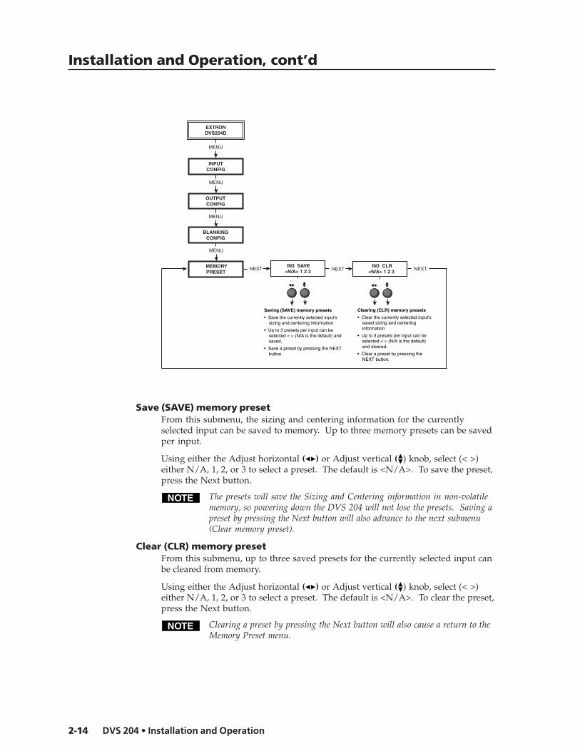
NEXT IN3 SAVE <N/A> 1 2 3
IN3 CLR <N/A> 1 2 3NEXT NEXT
INPUTCONFIG
MENU
Saving (SAVE) memory presets
• Save the currently selected input's sizing and centering information
• Up to 3 presets per input can be selected < > (N/A is the default) and saved.
• Save a preset by pressing the NEXT button.
Clearing (CLR) memory presets
• Clear the currently selected input's saved sizing and centering information
• Up to 3 presets per input can be selected < > (N/A is the default) and cleared.
• Clear a preset by pressing the NEXT button.
BLANKINGCONFIG
MENU
MEMORYPRESET
MENU
Save (SAVE) memory presetFrom this submenu, the sizing and centering information for the currentlyselected input can be saved to memory. Up to three memory presets can be savedper input.
Using either the Adjust horizontal ( ) or Adjust vertical ( ) knob, select (< >)either N/A, 1, 2, or 3 to select a preset. The default is <N/A>. To save the preset,press the Next button.
The presets will save the Sizing and Centering information in non-volatilememory, so powering down the DVS 204 will not lose the presets. Saving apreset by pressing the Next button will also advance to the next submenu(Clear memory preset).
Clear (CLR) memory presetFrom this submenu, up to three saved presets for the currently selected input canbe cleared from memory.
Using either the Adjust horizontal ( ) or Adjust vertical ( ) knob, select (< >)either N/A, 1, 2, or 3 to select a preset. The default is <N/A>. To clear the preset,press the Next button.
Clearing a preset by pressing the Next button will also cause a return to theMemory Preset menu.

2-15DVS 204 • Installation and Operation
Recalling a presetRecalling a saved preset requires that the desired input be currently selected andthat the input button be pressed successively to activate each saved preset (up tothree). Each saved preset will display the LCD message “Input #X Memory Y”where “X” refers to the input (1 to 4) and “Y” refers to the preset (1 to 3).
The absence of any saved presets will not display the “Input #X Memory Y”LCD message for the absent preset.
The presets are specific to a selected output rate. If the output rate issubsequently changed, the previously saved preset will have no effect on thevideo output. However, if the original output rate is later restored for asaved preset, the preset will again apply to that output rate.
Advanced ConfigurationThe following flowchart provides an overview of the Advanced Configurationsubmenus and the options for each setting.
Detail controlThis submenu allows adjustment of the image detail (sharpness) of the outputdisplay. The adjustment ranges from 0 to 63. The default is 16.
Using either the Adjust horizontal ( ) or Adjust vertical ( ) knob, adjust thedetail while observing the output display.
Filter modeThe Filter mode, when set “On”, reduces or eliminates aliasing and the resultant“jail bar” effect. For digital displays, set the filter “On” to reduce or eliminatehigh frequency noise. For CRT output, set the filter “Off”.
Use either the Adjust horizontal ( ) or Adjust vertical ( ) knob to specify thismode as “On” or “Off”. The default is “On”.
EXTRONDVS204D
OUTPUTCONFIG
MENU
INPUTCONFIG
MENU
BLANKINGCONFIG
MENU
MEMORYPRESET
MENU
ENH MODE <OFF> ON
NEXT
ADVANCEDCONFIG
MENU
DETAIL 016
NEXT
FILTER OFF <ON>
NEXT
BLUEMODE <OFF> ON
NEXT
AUTOSW <OFF> ON
NEXT
NEXT
Either Adjust knob is usedto adjust the submenus
Detail (sharpness)• Ranges from 0 to 63. (default is 16)
Filter• On (default)• Off
Display blue and sync only• On• Off (default)
Autoswitch mode• On• Off (default)
Enhanced mode (gain control)• Off (default)• On
RGB DLY 0.0 SEC
RGB delay time• 0.0 to 5.0 seconds in 0.5 sec. increments. (default is 0.0)
2:2 PLDN <OFF> ON
PAL film mode (2:2 pulldown detection)• On• Off (default)
DETAIL 016
Detail (sharpness)• Ranges from 0 to 63. (default is 16)
NEXT
NEXT

Installation and Operation, cont’d
DVS 204 • Installation and Operation2-16
Blue modeTo aid in setup of the scaler’s color and tint, the Blue mode can be set from thissubmenu to “On” so that only sync and blue video signals will be passed to thedisplay.
Use either the Adjust horizontal ( ) or Adjust vertical ( ) knob to specify thismode. The default is “Off”.
The Blue mode will be effective for YUV input signals. YC input signalswill pass Y, but not C, so the output display will be black-and-white only.
Autoswitch (Autosw) modeThe Autoswitch mode causes the highest numbered input that has a signalpresent to be automatically selected. For example, if both Inputs 1 and 3 haveactive input signals, Input 3 will be selected.
From this submenu, use either the Adjust horizontal ( ) or Adjust vertical ( )knob to specify this mode as “On” or “Off”. The default is “Off”.
The Autoswitch mode ignores the presence of an SDI input signal, so anyinput which is assigned an active SDI signal will not be selected.
Enhanced (Enh) modeWhen the Enhanced mode is set “On”, automatic gain control of the video inputsignal is enabled. If the input signal level is too weak, the signal gain will beincreased, and if the input signal level is excessive, the signal gain will bedecreased.
From this submenu, use either the Adjust horizontal ( ) or Adjust vertical ( )knob to specify this mode as “On” or “Off”. The default is “Off”.
The Enhanced mode will only be effective on composite and S-video inputsignals.
2:2 Pulldown detection (PAL Film mode detect) submenuFor the currently selected input, set this feature to “On” if the source is PAL videothat originated in film. For standard PAL video sources, such as cameras, set thisfeature to “Off” (default).
This feature does not apply to NTSC video sources since filmmode (3:2 pulldown) is automatically detected for those signals.
From this submenu, use either the Adjust horizontal ( ) knob or Adjust vertical( ) knob to specify this mode as “On” or “Off”.
RGB delay (Triple-Action Switching)With Triple-Action Switching, the DVS 204 switches to the new sync signalbefore switching RGB (video) signals. RGB delay allows the display device toadjust to the new sync timing after a brief delay (during which the display isblanked) before displaying the new picture, which will appear without glitches.Triple-Action Switching is also known as video mute switching.
Use the Adjust horizontal ( ) knob or Adjust vertical ( ) knob to select theblanking period (RGB delay time) from 0 seconds (default) to 5 seconds in0.5 second steps.

2-17DVS 204 • Installation and Operation
Exit MenuFrom this submenu, press the Next button to return to the Default menu cycle, orpress the Menu button to return to the Input Configuration menu.
EXTRONDVS204D
BLANKINGCONFIG
MENU
INPUTCONFIG
MENU
MEMORY PRESET
MENU
ADVANCED CONFIG
MENU
EXITMENU
MENU
MENU
NEXT
Image AdjustmentsImage adjustments apply to scaled video output only; RGB signals are passedthrough without adjustments. Sizing and centering image adjustments can bestored in memory as a preset (see the “Memory Preset” section in this chapter)and can be set separately for each input.
Color, tint, brightness, contrast, centering, sizingTo adjust an image for color, tint, brightness, contrast, centering, or sizing followthe steps below. An example of making color adjustments, shown in thefollowing flowchart, demonstrates the process, which is similar for all the otherimage adjustments.
1. Press the input selection button of the input you wish to adjust.
2. Toggle the appropriate image adjustment button (Color/Tint, Brightness/Contrast, Centering, and Sizing). The LCD display will show the name ofthe adjustments and the value of the current setting.
Col Tint128 114
Inputselectionbutton
COL/TNT
INPUT 3S-VIDEO
10 sec.timeout
NOTE The Adjust horizontal knob and the Adjust vertical knob are used to adjust the image settings on the left and
right sides of the LCD screen, respectively.
Poweron
EXTRONDVS204D
2 sec.
2 sec.
INPUT 1CMPOSITE
852 x480 @60 2 sec. 2 sec.
NOSIGNAL
2 sec.
* The No Signal default menu only occurs if there is no signal present at the currently selected input connector.
Installation and Operation, cont’d
DVS 204 • Installation and Operation2-18
3. Rotate the Adjust horizontal knob ( ) or Adjust vertical knob ( ) to select alevel from the following adjustment ranges:
The Adjust knobs have no mechanical limits to their rotation.
• Color and Tint (Col/Tnt): 0 to 255 (see note below)
• Brightness and Contrast (Brt/Cont): 0 to 255
• Centering (Center): 0 to 255
• Sizing (Size)
Rotating the horizontal Adjustment knob ( ) clockwise orcounterclockwise will increase or decrease, respectively, the horizontalsizing. Rotating the vertical Adjustment knob ( ) clockwise orcounterclockwise will increase or decrease, respectively, the verticalsizing. The visual indicator on the LCD will stop moving when theupper or lower sizing limit has been reached.
The scaler will time-out to the default menu after 10 seconds.
4. Repeat steps 2 and 3 for each image adjustment to be made for that input.
The LCD display will indicate that a Tint adjustment is not available (N/A)for Input 2 (component) or Input 4 (RGB, RGBS, RGBcvS).
Input ResetEach input of the DVS 204 scaler can be reset to its default centering and sizingvalues by holding down the specific input button until the Input # Reset messageis displayed on the LCD screen.
System ResetThe DVS 204 can be reset to all of its default values by holding down the Input 1button while simultaneously plugging in the power cord. The System Resetmessage will be displayed on the LCD screen.

2-19DVS 204 • Installation and Operation
EXTRONDVS204D
2 sec.
2 sec.
INPUT 1CMPOSITE
852 x480 @60 2 sec. 2 sec.
NOSIGNAL
2 sec.
* The No Signal default menu only occurs if there is no signal present at the currently selected input connector.
COL/TNT
10 sec.timeout
Press for2 seconds*
CENTER
EXE MODEENABLED
EXTRONDVS204D
2 sec.
2 sec.
INPUT 1CMPOSITE
852 x480 @60 2 sec. 2 sec.
NOSIGNAL
2 sec.
* The No Signal default menu only occurs if there is no signal present at the currently selected input connector.
COL/TNT
10 sec.timeout
Press for2 seconds*
CENTER
EXE MODEDISABLED
Enable Executive Mode
Disable Executive Mode
Front Panel Security Lockout (Executive Mode)To prevent accidental changes to settings, press the Col/Tnt and Center buttonssimultaneously for 2 seconds to enable the DVS 204’s Executive mode. Executivemode locks all front panel functions. The menu system will still return to theDefault menu when 10 seconds have elapsed. The IR 901 will still be able tocontrol the scaler after Executive mode has been enabled. When Executive modeis active, all functions and adjustments can still be made through RS-232 control.For details on RS-232 control, see chapter three.
To disable the Executive mode, press the Col/Tnt and Center buttonssimultaneously for 2 seconds.

Installation and Operation, cont’d
DVS 204 • Installation and Operation2-20
IR 901 Infrared Remote ControlThe IR 901, shown at right, replicates all of the frontpanel controls except the Menu and Next buttons. IfExecutive mode has been enabled on the DVS 204,input selection and adjustments can still be made fromthe IR 901. You must use the DVS 204’s front panel orthe Windows-based control program (via an RS-232device) to configure and program the scaler. Seechapter three, “Serial Communication”, for details.
The topmost part of the IR 901 features three AspectRatio Preset buttons, a Freeze button and four inputselection buttons (1, 2, 3, 4). Inputs 5 and 6, and theTake button are not functional. The middle portion ofthe IR 901 features the size and centering buttons. Thebottom part contains the adjustment controls for color,tint, brightness, contrast, and detail adjustments. Thesharpness buttons are not functional.
Aspect ratio presetsUp to three saved memory presets of sizing andcentering information may be recalled selecting thesebuttons. See the “Memory Preset” section earlier inthis chapter.
Freezing an inputTo freeze the input being displayed, press the FreezeOn/Off button. To unfreeze the input, press the Freezebutton again.
Selecting an inputTo select an input source, press an input button (1 through 4).
Size and centerUse the Size and Center buttons to adjust the sizing and centering aspects of adisplayed image.
Image adjustmentsThe color, tint, brightness, contrast, and detail of a displayed image may beincreased or decreased by using the appropriate Image Adjustment buttons at thebottom of the IR 901.
DVS Remote

2-21DVS 204 • Installation and Operation
TroubleshootingThis section gives recommendations on what to do if you have problemsoperating the DVS 204, and it provides examples and descriptions for someimage problems you might encounter.
The following are some tips to help you in troubleshooting.
1. Some symptoms may resemble others, so you may want to look through allof the examples before attempting to solve the problem.
2. Be prepared to backtrack in case the action taken doesn’t solve the problem.
3. It may help to keep notes and sketches in case the troubleshooting processgets lengthy. This will also give you something to discuss if you call fortechnical support.
4. Try simplifying the system by eliminating components that may haveintroduced the problem or made it more complicated.
5. For sync-related problems: Portable digital projectors are designed tooperate close to the video source. Sync problems may result from usinglong cables or from improper termination. A sync adapter, such as Extron’sASTA (active sync termination adapter), may help solve these problems.
6. For LCD and DLP projectors and plasma displays: In addition to the sync-related information above, check the user’s manual that came with theprojector for troubleshooting tips, as well as for settings and adjustments.Each manufacturer may have its own terms, so look for terms like “autosetup”, “auto sync”, “pixel phase”, and “tracking”.
Operating problemsThe table below shows some common operating problems and their solutions.
Problem Cause Solution
No image appears. The input signal is Attach an input device that isincompatible. compatible with NTSC 3.58,
NTSC 4.43, PAL, or SECAM.Freeze mode was Deactivate freeze modeentered when theimage was black.The scaled output Change the scaled output to arate is too high for compatible resolution.the display.
The image is frozen. Freeze mode is on. Deactivate freeze mode.If that does not work, unplug thepower cord from the scaler, thenplug it back in.
The image is flashing. The scaled output Change the scaled output to arate is too high for compatible resolution.the display.
The image is green. The output sync Turn off sync on green.is configured forsync on green.
The image is too soft. The detail level Change the detail level.needs to bechanged.

Installation and Operation, cont’d
DVS 204 • Installation and Operation2-22

DVS 204
3Chapter Three
Serial Communication
RS-232 Programmer’s Guide
Control Software for Windows

DVS 204 • Serial Communication3-2
Serial Communication
The DVS 204 can be remotely controlled via a host computer or other device(such as a control system) attached to the rear panel Remote connector. Thecontrol device (host) can use either Extron’s Simple Instruction Set (SIS)commands or the graphical control program for Windows.
The scaler uses a protocol of 9600 baud, 1 stop bit, no parity, and no flow control.
The rear panel RS-232 9-pin D connector has the following pin assignments:
Pin RS-232 function Description
1 Input #1 Contact closure2 Tx Transmit data3 Rx Receive data4 Input #2 Contact closure5 Gnd Signal ground6 Input #3 Contact closure7 Input #4 Contact closure8 – No connection9 Hardwired IR IR input
RS-232 Programmer’s Guide
Host-to-scaler communicationsSIS commands consist of one or more characters per field. No special charactersare required to begin or end a command sequence. When the DVS 204determines that a command is valid, it executes the command and sends aresponse to the host device. All responses from the scaler to the host end with acarriage return and a line feed (CR/LF = ), which signals the end of theresponse character string. A string is one or more characters.
It is also possible to send several SIS commands back-to-back in sequence.
Scaler-initiated messagesWhen a local event such as a front panel selection or adjustment takes place, theDVS 204 scaler responds by sending a message to the host. No response isrequired from the host. The scaler-initiated messages are listed here(underlined).
(C) Copyright 2002, Extron Electronics, DVS 204, Vx.xx The DVS 204 sends the copyright message when it first powers on. Vx.xx is thefirmware version number.
C hn X1 (where X1 is the input number)The DVS 204 sends this response when an input is switched.
Error responsesWhen the scaler receives a valid SIS command, it executes the command andsends a response to the host device. If the DVS 204 is unable to execute thecommand because the command is invalid or it contains invalid parameters, itreturns an error response to the host.
The error response codes and their descriptions are as follows:
E01 – Invalid input channel number (the number is too large)E10 – Invalid commandE11 – Invalid preset numberE13 – Invalid value (the number is out of range/too large)E17 – Illegal command for this signal type.
DB9 Pin LocationsFemale
5 1
9 6

3-3DVS 204 • Serial Communication
Using the command/response tablesThe command/response tables on the next page list valid command ASCII codes,the scaler’s responses to the host, and a description of the command’s functionor the results of executing the command. Upper and lower case characters may beused interchangeably in the command field.
The ASCII to HEX conversion table at left is for use with thecommand/response tables.
ASCII to Hex conversion table
ASCII to HEX Conversion Table
•
X12 = Detected input signal standard (0 through 4)0 = none1 = NTSC 3.582 = PAL3 = NTSC 4.434 = SECAM– = not applicable (occurs when the input is
set for RGB, YUV, or progressive YUV)
X13 = Detail level (0 through 63)
X14 = Adjustment range (0 through 127)
X16 = Executive mode status (0 through 2)0 = disabled (executive mode off, normal mode on)1 = enabled, image adjustments are locked
X17 = Blanking adjustment range (0 through 127 lines)
X19 = Input configuration preset (1 through 3)
X20 = Scaler refresh rate1 = 50 Hz2 = 56 Hz (1280x768 only)3 = 60 Hz4 = 75 Hz5 = AFL* (50 Hz for PAL or 59.94 Hz for
NTSC)6 = True rate (72 Hz for NTSC or 100 Hz for
PAL)
*NOTE: Lock or AFL is Accu-RATE Frame Lock™
The command/response tables use symbols (defined below) to represent variables.
Symbol definitions= CR/LF (carriage return/line feed) (hex 0D 0A)
• = Space
Esc = Escape key
X1 = Specific input number (0 through 4)0 = no input1 = input 1, 2 = input 2, and so forth
X2 = 0 = off, 1 = on
X4 = Video signal type (1 through 7)1 = composite video2 = YC3 = YUV4 = RGB5 = RGBS6 = RGBcvS7 = SDI (serial digital interface)
X5 = Input (1 to 4)
X8 = Controller firmware version (listed totwo decimal places e.g.: x.xx)
X10 = Picture adjustment range (0 through 255)
X11 = Scaler resolution1 = 640x4802 = 800x6003 = 848x4804 = 852x4805 = 1024x7686 = 1280x7687 = 1280x10248 = 1360x7659 = 1365x102410 = 480p11 = 720p12 = 1080p13 = 1080i14 = 1400x105015 = 576p

Serial Communication, cont’d
DVS 204 • Serial Communication3-4
Command/response table for SIS commands
Command ASCII Command Response Additional description(host to scaler) (scaler to host)
Input selectionSelect video input X5 ! C X5 Video Input X1 .
Example: 3! C3 Example: select video Input 3.
Memory presetRecall input configuration preset X19 . Rpre X19 Recall input preset X19 .Save input configuration preset X19 , Spre X19 Save to input preset X19 .
Input video type (Inputs 2 and 4 only)Set video signal type X5 * X4 \ X5 Typ X4 Select Input X5 (Inputs 2 and 4
only) and assign it a video typeX4 . Video type X4 is defined tobe: 1 = video, 2 = S-video, 3 = YUV, 4 =RGB, 5 = RGBS, 6 = RGBcvS, and SDI.For SDI input, substituteX5 with X1 where the SDI inputcan be assigned to Input X1 (0,1, 2, 3, or 4 with 0 meaningthere is no SDI input).
Example: 2*3\ 2Typ3 Example: set Input 2 to 3 (YUV)View the video signal type X5 \ X5 Typ X4 Show the video signal type.
Example: 2\ 2Typ3 Example: show Input 2 video type = 3.
ColorSet a specific color value X10 C Col X10 Specify a color adjustment level.
Example: 47C Col047 Example: set the color adjustment to 47.
Increment +C Col X10 Increase color adjustment level.Decrement -C Col X10 Decrease color adjustment level.View the color value C Col X10 Show the color adjustment.
TintSet a specific tint value X10 T Tin X10 Specify a tint adjustment level.
Example: 176T Tin176 Example: set the tint to 176.Increment +T Tin X10 Increase tint adjustment level.Decrement -T Tin X10 Decrease tint adjustment level.View the tint value T Tin X10 Show the tint adjustment.
ContrastSet a specific contrast value X10 ^ Con X10 Specify the contrast adjustment.Increment +^ Con X10 Increase the contrast.Decrement -^ Con X10 Decrease the contrast.View the contrast value ^ Con X10 Show the contrast setting.
BrightnessSet a specific value X10 Y Brt X10 Specify the brightness
adjustment.Increment +Y Brt X10 Increase the brightness.Decrement -Y Brt X10 Decrease the brightness.View the brightness value Y Brt X10 Show the brightness setting.
Detail modeSet the detail level X13 D Det X13 Specify the detail level.View the detail value D Det X13 Show the detail setting.Increment +D Det X13 Increase detail level.Decrement -D Det X13 Decrease detail level.
3-5DVS 204 • Serial Communication
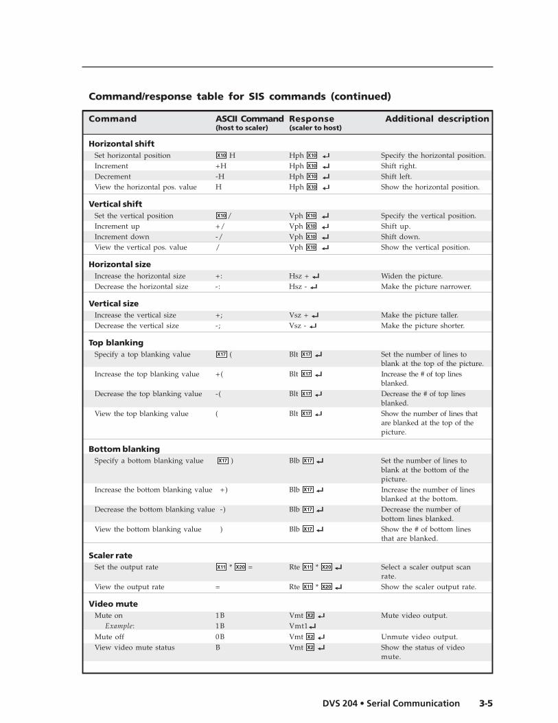
Horizontal shiftSet horizontal position X10 H Hph X10 Specify the horizontal position.Increment +H Hph X10 Shift right.Decrement -H Hph X10 Shift left.View the horizontal pos. value H Hph X10 Show the horizontal position.
Vertical shiftSet the vertical position X10 / Vph X10 Specify the vertical position.Increment up +/ Vph X10 Shift up.Increment down -/ Vph X10 Shift down.View the vertical pos. value / Vph X10 Show the vertical position.
Horizontal sizeIncrease the horizontal size +: Hsz + Widen the picture.Decrease the horizontal size -: Hsz - Make the picture narrower.
Vertical sizeIncrease the vertical size +; Vsz + Make the picture taller.Decrease the vertical size -; Vsz - Make the picture shorter.
Top blankingSpecify a top blanking value X17 ( Blt X17 Set the number of lines to
blank at the top of the picture.Increase the top blanking value +( Blt X17 Increase the # of top lines
blanked.Decrease the top blanking value -( Blt X17 Decrease the # of top lines
blanked.View the top blanking value ( Blt X17 Show the number of lines that
are blanked at the top of thepicture.
Bottom blankingSpecify a bottom blanking value X17 ) Blb X17 Set the number of lines to
blank at the bottom of thepicture.
Increase the bottom blanking value +) Blb X17 Increase the number of linesblanked at the bottom.
Decrease the bottom blanking value -) Blb X17 Decrease the number ofbottom lines blanked.
View the bottom blanking value ) Blb X17 Show the # of bottom linesthat are blanked.
Scaler rateSet the output rate X11 * X20 = Rte X11 * X20 Select a scaler output scan
rate.View the output rate = Rte X11 * X20 Show the scaler output rate.
Video muteMute on 1B Vmt X2 Mute video output.
Example: 1B Vmt1Mute off 0B Vmt X2 Unmute video output.View video mute status B Vmt X2 Show the status of video
mute.
Command/response table for SIS commands (continued)
Command ASCII Command Response Additional description(host to scaler) (scaler to host)
Serial Communication, cont’d
DVS 204 • Serial Communication3-6
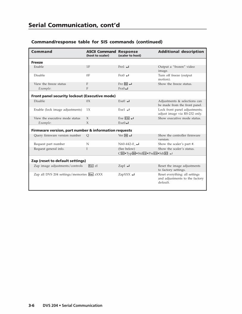
FreezeEnable 1F Frz1 Output a “frozen” video
image.Disable 0F Frz0 Turn off freeze (output
motion).View the freeze status F Frz X2 Show the freeze status.
Example: F Frz0
Front panel security lockout (Executive mode)Disable 0X Exe0 Adjustments & selections can
be made from the front panel.Enable (lock image adjustments) 1X Exe1 Lock front panel adjustments;
adjust image via RS-232 only.View the executive mode status X Exe X16 Show executive mode status.
Example: X Exe0
Firmware version, part number & information requestsQuery firmware version number Q Ver X8 Show the controller firmware
version.Request part number N N60-442-0_ Show the scaler’s part #.
Request general info. I (See below) Show the scaler’s status.C X1 •Typ X4 •Std X12 •Pre X19 •Sdi X1
Zap (reset to default settings)Zap image adjustments/controls Esc zI ZapI Reset the image adjustments
to factory settings.Zap all DVS 204 settings/memories Esc zXXX ZapXXX Reset everything: all settings
and adjustments to the factorydefault.
Command/response table for SIS commands (continued)
Command ASCII Command Response Additional description(host to scaler) (scaler to host)

3-7DVS 204 • Serial Communication
The syntax for setting a special function is X? * X! # where X? is the function number and X! is thevalue. To view a function’s setting, use X? # where X? is the function number. In the following table thevalues of the X? variable are different for each command/function. These values are given in therightmost column.
Command/response table for special function SIS commands
Command ASCII Command Response X! values(host to scaler) (scaler to host) and additional descriptions
Enhanced modeEnhanced mode 12 * X! # Enh X! 0 = off,
1 = on,Example: 12*1# Enh1 Example: enable enhanced mode.
Scaler settingsOutput signal 6 * X! # Syn X! 0 = RGB
1 = YUV2 = RGsB (sync on green, SOG)
Example: 6*0# Syn0 Example: RGB sync output
Scaler output polarity 7 * X! # Pol X! 0 = H-/V- (default)1 = H-/V+2 = H+/V-3 = H+/V+
Example: 7*1# Pol1 Example: H-/V+ sync polarity
Blue screenBlue screen (blue & sync output only) 8* X! # Blu X! 0 = off (default) (RGB & sync output)
1 = on (blue video & sync output only)
Example: 8*1# Blu1 Example: blue & sync output for
setup.
Auto switchAuto switch mode 10* X! # Aut X! 0 = off (default), 1 = on
Example: 10*1# Aut1 Example: enable auto switch mode.
Reconstruction filterReconstruction filter 11* X! # Fil X! 0 = off, 1 = on (default)
Example: 11*1# Fil1 Example: enable the reconstruction
filter.
PAL Film mode (2:2 pulldown detection)PAL film mode detection 18* X! # Flm X! 0 = off (default), 1 = on
Example: 18*1# Flm1 Example: enable PAL film mode.
detection
H Format (sync output format for “H” connector)RGBS H format 15* X! # HFm X! 0 = H – horizontal sync (default)
1 = HV – composite syncExample: 15*1# HFm1 Example: Output composite sync
on “H” connector. See “H Format”and “RGB pass-through” sections inchapter two for a completedescription of this function.
RGB delay timesRGB delay 3 * X! # RGB X! 0 = 0.0 seconds (default),
1 = 0.5 seconds, 2 = 1.0seconds, ... in ½ second stepsup to 10 = 5.0 seconds
Example: 3*7# RGB07 Example: 3.5 second RGB delay

Serial Communication, cont’d
DVS 204 • Serial Communication3-8
Control Software for WindowsThe included Extron DVS 204 Control Program for Windows offers another wayto control the DVS 204 via RS-232 connection in addition to the SimpleInstruction Set commands. The control program’s graphical interface includesthe same functions as those on the scaler’s front panel and some additionalfeatures that are only available through the Windows-based software.
The control software is compatible with Windows 95/98, Windows NT, andWindows 2000. Extron’s DVS 204 Control Program is included with the scaler,and updates can be downloaded from the Extron Web site(http://www.extron.com).
Installing the softwareThe control program is contained on a set of 3.5-inch diskettes, and it requiresapproximately 2 MB (megabytes) of hard disk space.
To install the software on the hard drive:
1. Run SETUP.EXE from the floppy disk.2. Follow the instructions that appear on the screen.
By default the installation creates a C:\DVS 204 directory, and it places two icons(DVS 204 Control Pgm and DVS 204 Help) into a group or folder named “ExtronElectronics”.
Using the control programMany items found in the DVS 204 Control Program are also accessible via frontpanel controls and the LCD menus described in chapter two. Refer to chaptertwo for details on features and settings. The DVS 204 Help Program providesinformation on settings and on how to use the control program itself. Somefeatures, including the miscellaneous options, are only available via this controlprogram. These features are described in the sections of this chapter thatcorrespond to the parts of the control program where the features are found.
1. To run the control program, double-click on the DVS 204 Control Pgm iconin the Extron Electronics group or folder. The Comm menu appears on thescreen.
2. Click on the comm port that is connected to the DVS 204’s RS-232 port.The Extron DVS 204 Control Program windows appear.

3-9DVS 204 • Serial Communication
3. Click on the I/O Config button to configure the inputs from the I/OConfiguration Window.
Using the help programFor information on program features, press the F1 computer key, orclick on the Help menu from within the DVS 204 Control Program, ordouble-click on the DVS 204 Help icon in the Extron Electronics groupor folder.
For explanations of buttons or functions, click on the tabs in the help screen toreach the desired screen. Use a mouse or the Tab and Enter keys to select abutton/function. A description and tips on using the program will appear onscreen.

Serial Communication, cont’d
DVS 204 • Serial Communication3-10

DVS 204
AAppendix
Appendix
Specifications
Part Numbers and Accessories
Firmware Upgrade Installation
Serial Digital Interface (SDI) Card Installation

DVS 204 • AppendixA-2
Appendix
Specifications
Video inputNumber/signal type .................. 1 (RGBHV, RGBS, RGsB) pass-through, RGBS, RGBcvS
1 composite video, S-video, component video (Y, R-Y, B-Y)1 S-video, 1 SDI (optional, DVS 204D only)1 composite video
Connectors .................................. (1) 15-pin HD female .............. RGB pass-through, RGBS, RGBcvS3 BNC female .......................... component video, S-video, composite video1 BNC female .......................... SDI (DVS 204D, DVS 204D 12 V only)(1) 4-pin mini DIN female ...... S-video1 BNC female .......................... composite video
Nominal level ............................... 1 Vp-p for Y of component video and S-video, and for composite video0.7 Vp-p for RGB and for R-Y and B-Y of component video0.3 Vp-p for C of S-video
Minimum/maximum levels ...... Analog: 0.0 V to 1.0 Vp-p with no offsetImpedance ................................... 75 ohmsHorizontal frequency .................. NTSC 3.58, NTSC 4.43, PAL, SECAMVertical frequency ....................... NTSC 3.58, NTSC 4.43, PAL, SECAMResolution range .......................... NTSC 3.58, NTSC 4.43, PAL, SECAMReturn loss .................................... <-30 dB @ 5 MHzDC offset (max. allowable) ......... 1.5 V
Video processingDecoder ......................................... 9 bit digitalDigital sampling ........................... 24 bit, 8 bits per color; 13.5 MHz standardColors ............................................ 16.78 million
Video outputNumber/signal type .................. 1 scaled or pass-through RGBHV, RGBS, RGsB;
or scaled component video (Y, R-Y, B-Y)Connectors .................................. 6 female BNC
1 female 15-pin HDNominal level ............................... 1 Vp-p for Y of component video
0.7 Vp-p for RGB and for R-Y and B-Y of component videoMinimum/maximum levels ...... 0.0 V to 0.7 Vp-pImpedance .................................... 75 ohmsScaled resolutions ........................ 640x4801,3,4,5,6, 800x6001,3,4,5,6, 848x4801,3,4,5,6, 852x4801,3,4,5,6, 1024x7681,3,4,5,6,
1280x7682,5,6, 1280x10241,3,4,5,6, 1360x7651,3,4,5,6, 1365x10241,3,4,5,6,1400x10501,3,4,5,6, HDTV 480p3,5, 576p1,5, 720p3,5, 1080p3,5, and 1080i1,3,5
1 = at 50 Hz 2 = at 56 Hz 3 = at 60 Hz 4 = at 75 Hz5 = locked to the current input’s vertical refresh rate (Accu-RATE FrameLock)6 = True Rate
SyncInput type ..................................... (RGBHV, RGBS, RGsB) pass-through, RGBS, RGBcvSOutput type .................................. RGBHV, RGBS, RGsBStandards ...................................... NTSC 3.58, NTSC 4.43, PAL, SECAMInput level ..................................... 0 V to 1.0 Vp-pOutput level .................................. TTL: 5.0 Vp-p, unterminatedInput impedance .......................... 75 ohms

A-3DVS 204 • Appendix
Output impedance ....................... 75 ohmsMax input voltage ........................ 5 Vp-pMax. propagation delay .............. 20 nsPolarity .......................................... Positive or negative (switch-selectable)
Control/remote — decoder/scalerSerial control port ........................ RS-232, 9-pin female D connectorBaud rate and protocol ............... 9600 baud, 8 data bits, 1 stop bit, no paritySerial control pin configurations 1 = input 1 select
2 = TX3 = RX4 = input 2 select5 = GND6 = input 3 select7 = input 4 select8 = n/a9 = hardwired IR
Contact closure ............................ 9-pin female D connector (same as RS-232 connector)Contact closure pin configurations See pins 1, 4, 6, and 7 above.IR controller module ................... Extron IR 901 (optional)Program control .......................... Extron’s control/configuration program for Windows®
Extron’s Simple Instruction Set (SIS™)
GeneralPower
DVS 204, DVS 204D ......... 100VAC to 240VAC, 50/60 Hz, 30 watts, internal, autoswitchableDVS 204/204D 12VDC .... 100VAC to 240VAC, 50/60 Hz, 36 watts, external, autoswitchable; to 12
VDC,3 A power supply. Product requires 2 A.
Temperature/humidityAll models ......................... Storage: -40 to +158 °F (-40 to +70 °C) / 10% to 90%, noncondensingDVS 204, DVS 204D ......... Operating: +32 to +113 °F (0 to +45 °C) / 10% to 90%, noncondensingDVS 204/204D 12VDC .... Operating: +32 to +122 °F (0 to +50 °C) / 10% to 90%, noncondensing
Rack mount .................................. Yes, with optional rack shelf, part #60-190-01Enclosure type .............................. MetalEnclosure dimensions ................. 1.75" H x 8.75" W x 9.5" D (1U high, half rack wide)
4.4 cm H x 22.2 cm W x 24.1 cm D(Depth excludes connectors and knobs. Width excludes rack ears.)
Product weight ............................. 3.3 lbs (1.5 kg)Shipping weight ........................... 6 lbs (3 kg)Vibration ....................................... ISTA 1A in carton (International Safe Transit Association)Listings .......................................... UL, CULCompliances ................................. CE, FCC Class A, VCCI, AS/NZS, ICESMTBF ............................................. 30,000 hoursWarranty ....................................... 3 years parts and labor
All nominal levels are at ±10%.
Specifications are subject to change without notice.

Appendix, cont’d
DVS 204 • AppendixA-4
Part Numbers and Accessories
Included partsThese items are included in each order for a DVS 204 scaler:
Included parts Part number
DVS 204, 204 D, 204 12V, 204 D 12V (1) 60-442-01, -02, -11, -12
Rubber feet (self-adhesive) (4) 25-020-02
IEC power cord
Tweeker (small screwdriver)
DVS 204 User’s Manual
DVS 406 Windows-based control program
AccessoriesThese items can be ordered separately:
Accessories Part number
IR 901 remote control 70-152-01
Rack shelf mounting kit 60-190-01
SDI video input card 70-168-01

A-5DVS 204 • Appendix
Firmware Upgrade InstallationIn some cases, the DVS 204’s firmware may require replacement with an updatedversion. There are three user-replaceable firmware chips: U41 — the mainmicrocontroller, U38, and U17. The numbers are printed on the circuit board. Werecommend that you send the unit to Extron for service and updates.
Changes to firmware must be performed by authorized service personnelonly. Some DVS 204 firmware updates must be performed at theExtron factory.
Follow these steps to replace firmware in the scaler.
1. Disconnect the AC or 12 VDC power cord from the DVS 204 to removepower from the unit.
To prevent electric shock or damage, always unplug the DVS 204 scalerfrom the AC or DC power source before opening the enclosure.
2. Remove the scaler from the rack or furniture.
3. Remove the cover of the scaler (the top half of the enclosure) by removingthe screws, then lifting the cover straight up.
COMPOSITE
1
DVS 204
DIGITAL VIDEO SCALER
YUV
2
S-VIDEO
3
RGB
4
BRT/CONT
COL/TNT
SIZE
CENTERMENU
NEXT
ADJUST
IR
Lift CoverStraight Up.
Remove (4)Screws fromTop.
Do not touch any switches or other electronic components inside thescaler. Doing so could damage the scaler. Electrostatic discharge (ESD)can damage IC chips even though you cannot feel it. You must beelectrically grounded before proceeding with firmware replacement. Agrounding wrist strap is recommended.
4. Locate the firmware chip(s) to be replaced on the circuit board, as shown inthe following illustration.

Appendix, cont’d
DVS 204 • AppendixA-6
Locating the three firmware IC chips
5. After you are electrically grounded, the U17 IC chip orU38 IC chip may be removed by grasping it firmly withyour fingers and pulling it out, then continuing to step8.
Removal of the U41 IC chip requires a PLCC IC pullertool. To remove the U41 chip, align the hooks of aPLCC IC puller tool with the slots located in oppositeends of the U41 firmware chip.
6. Insert the hooks into the slots, and squeeze the toolgently to grasp the chip.
7. Pull the chip straight outof the socket, and set itaside.
8. For U17 and U38, alignthe notch of the newfirmware chip with thenotch of the socket in thesame orientation as the old chip.
For U41, align the angled corner of the firmware chip with the angledcorner of the socket.
9. Gently, but firmly, press the chip into place in the socket.
10. Replace the top cover on the DVS 204 scaler, and fasten it with the screwsthat were removed in step 3.
11. Rack/furniture mount the scaler, and reconnect the AC or DC power cord.
U41Align Notches
U41
U17
U38

A-7DVS 204 • Appendix
Serial Digital Interface (SDI) Card InstallationThe optional SDI card may be installed in the scaler if it does not already have aninput for a serial digital interface signal. We recommend that you send the unitin to Extron for service and updates.
Changes to electronic components must be performed by authorizedservice personnel only.
Follow these steps to install an SDI card in the DVS 204.
1. Disconnect the AC or DC power cord from the DVS 204 to remove powerfrom the unit.
To prevent electric shock, always unplug the DVS 204 scaler from theAC power source before opening the enclosure.
2. Remove the scaler from the rack or furniture.
3. Remove the cover of the scaler (the top half of the enclosure) by removingthe screws, then lifting the cover straight up. See the top cover removaldiagram in the “Firmware Upgrade Installation” section.
Do not touch any switches or other electronic components inside thescaler. Doing so could damage the scaler. Electrostatic discharge (ESD)can damage IC chips even though you cannot feel it. You must beelectrically grounded before proceeding with any electronic componentreplacement. A grounding wrist strap is recommended.
4. Locate the SDI card standoff located near the middle rear portion of themain circuit board (looking from above with the front panel nearest to you).
5. Remove the adhesive SDI cover from the rear SDI connector opening of thescaler and position the SDI card at an angle with the SDI connectorprotruding from the rear SDI connector opening.
6. The SDI card has a 20-pin socket on the underside which should align withthe 20 pins on the main circuit board. Be sure to align the pins properly, in
SDI connector opening
SDI card standoff

Appendix, cont’d
DVS 204 • AppendixA-8
order to prevent bending the pins, before pressing the SDI card firmly inplace against the standoff. The mounting hole on the SDI card should nowbe directly over the standoff.
7. Insert the card’s installation screw through the SDI card’s mounting holeand gently tighten it into the standoff.
8. Install the SDI connector’s hex nut and keep the SDI card from twisting asthe nut is tightened.
9. Replace the top cover on the DVS 204 scaler, and fasten it with the screwsthat were removed in step 3.
10. Rack/furniture mount the scaler, and reconnect the AC power cord.
20-pin socket onback of SDI card
20-pin connectoron main board

FCC Class A NoticeNote: This equipment has been tested and found to comply with the limits for a Class A digital device,pursuant to part 15 of the FCC Rules. These limits are designed to provide reasonable protectionagainst harmful interference when the equipment is operated in a commercial environment. Thisequipment generates, uses and can radiate radio frequency energy and, if not installed and used inaccordance with the instruction manual, may cause harmful interference to radio communications.Operation of this equipment in a residential area is likely to cause harmful interference, in which casethe user will be required to correct the interference at his own expense.
Note: This unit was tested with shielded cables on the peripheral devices. Shielded cables must beused with the unit to ensure compliance.
Extron’s WarrantyExtron Electronics warrants this product against defects in materials and workmanship for a period ofthree years from the date of purchase. In the event of malfunction during the warranty periodattributable directly to faulty workmanship and/or materials, Extron Electronics will, at its option,repair or replace said products or components, to whatever extent it shall deem necessary to restoresaid product to proper operating condition, provided that it is returned within the warranty period,with proof of purchase and description of malfunction to:
USA, Canada, South America, Europe, Africa, and the Middle East:and Central America:
Extron Electronics Extron Electronics, Europe1230 South Lewis Street Beeldschermweg 6CAnaheim, CA 92805, USA 3821 AH Amersfoort
The Netherlands
Asia: Japan:
Extron Electronics, Asia Extron Electronics, Japan135 Joo Seng Road, #04-01 Kyodo BuildingPM Industrial Bldg. 16 IchibanchoSingapore 368363 Chiyoda-ku, Tokyo 102-0082
Japan
This Limited Warranty does not apply if the fault has been caused by misuse, improper handling care,electrical or mechanical abuse, abnormal operating conditions or non-Extron authorized modificationto the product.
If it has been determined that the product is defective, please call Extron and ask for an ApplicationsEngineer at (714) 491-1500 (USA), 31.33.453.4040 (Europe), 65.6383.4400 (Asia), or 81.3.3511.7655 (Japan)to receive an RA# (Return Authorization number). This will begin the repair process as quickly aspossible.
Units must be returned insured, with shipping charges prepaid. If not insured, you assume the riskof loss or damage during shipment. Returned units must include the serial number and adescription of the problem, as well as the name of the person to contact in case there are anyquestions.
Extron Electronics makes no further warranties either expressed or implied with respect to theproduct and its quality, performance, merchantability, or fitness for any particular use. In no eventwill Extron Electronics be liable for direct, indirect, or consequential damages resulting from anydefect in this product even if Extron Electronics has been advised of such damage.
Please note that laws vary from state to state and country to country, and that some provisions ofthis warranty may not apply to you.

© 2005 Extron Electronics. All rights reserved.
Extron Electronics, USA1230 South Lewis StreetAnaheim, CA 92805USA714.491.1500 Fax 714.491.1517
Extron Electronics, EuropeBeeldschermweg 6C3821 AH AmersfoortThe Netherlands+31.33.453.4040 Fax +31.33.453.4050
Extron Electronics, Asia135 Joo Seng Road, #04-01PM Industrial BuildingSingapore 368363+65.6383.4400 Fax +65.6383.4664
Extron Electronics, JapanKyodo Building16 IchibanchoChiyoda-ku, Tokyo 102-0082 Japan +81.3.3511.7655 Fax +81.3.3511.7656www.extron.com