
WS0-GCC1 - User's Manual (CC-Link Interface Module) SH(NA)-080909-A (03.10)

- 1 -
Digital Surveillance System
User’s Manual Triplex DVR
Vx1.3

- 2 -
Contents
Trademarks ................................................................................................................. 4 Precautions for Safety .............................................................................................. 4 Package Contents ..................................................................................................... 4 Chapter 1 Introduction ........................................................................................... 5 Chapter 2 Physical Unit ......................................................................................... 6 2.1 Front Panel……………………………………………………………………..7 2.2 Rear Panel………………………………………………………………………9 2.3 Remote controller……………………………………………………………11
Chapter 3 Getting Started .................................................................................... 12 Chapter 4 Hardware Setup .................................................................................. 13 4.1 Hard disk driver installation(for embedded)……………………………13 4.2 Hard disk driver installation(for removable HDD)……………………..14 4.3 Monitor Connection ............................................................................ 146 4.4 Camera Connection .............................................................................. 16 4.5 Sensor Connection ............................................................................. 177 4.6 Alarm Connection ............................................................................... 188 4.7 RS485 Singal Line Connection ........................................................... 18 4.8 Network Connection ........................................................................... 198 4.9 Mouse Connection ................................................................................ 19 4.10 USB Port Connection ........................................................................... 19 4.11 DVR Power Connection ....................................................................... 20 4.12 Power on the DVR ............................................................................... 20
Chapter 5 Main Menu ........................................................................................... 21 5.1 Enabling Triplex Functionality ............................................................ 22 5.2 Camera .................................................................................................... 22 5.3 Record .................................................................................................... 23 5.4 Sensor ..................................................................................................... 25 5.5 Motion Detection ................................................................................... 26 5.6 Screen ..................................................................................................... 27 5.7 Audio ....................................................................................................... 28 5.8 System .................................................................................................... 29 5.9 Language ................................................................................................ 36 5.10 Exit .......................................................................................................... 36
Chapter 6 Playback with Time Search Function ............................................. 37

- 3 -
Chapter 7 Backup via flash disk ...................................................................... 38 Chapter 8 Player & Viewer .................................................................................. 40 8.1 Player ........................................................................................................... 40
8.1.1 Menu Description .............................................................................. 40 8.1.2 Icon Description ............................................................................... 41 8.1.3 Playback with Saved Video Data ..................................................... 42 8.1.4 Convert Video Stream as Standard AVI Format ............................ 45
8.2 NetViewer Option for DVR Connection via Network ........................... 47 8.2.1 Menu Description .............................................................................. 47
8.3 Install and Set up the Remote Surveillance from IE Browser ..... 52 DDNS setup procedure………………........................................................................57 How to set up 2 DVRs under the same router for DDNS ….…….…………….66 Appendix……………………………………………………………………………………...73

- 4 -
Trademarks Any products, names and trademarks mentioned in this manual belong to their registered
legal companies.
Precautions for Safety 1. Do not install the equipment in a place with a great deal of moisture, dust or soot. 2. Do not install the equipment in a location subject to direct sunlight, or a location near
heat sources. 3. Keep the equipment away from vibration or materials with strong magnetic forces. 4. Normal range of working temperature is 5°C ~ 40°C. 5. Avoid a place of high temperature and humidity. 6. Operate in a place with steady foundation and good ventilation. 7. Avoid mechanical shock to the equipment. 8. Power must be switched off and unplugged before installation to prevent electric
shock or damage to the equipment. 9. Do not place any liquid such as water, coffee or other beverages on the equipment. 10. Maintain a suitable gap around the equipment for ventilation, which is necessary for
safe operation.
Package Contents 1. DVR Main Unit 2. Remote Controller with AAA battery * 2 (Option) 3. Power Adaptor 4. Software CD for installation If there is any damage, shortage or inappropriate item in the package, please contact with your local dealer.
- 5 -
Chapter 1 Introduction
This is a triplex digital video recorder (DVR) system for recording/retrieving video streams from 4 channels, 8 and up to 16CH at the same time. It adopts a digital image compression technology to compress the input channel video streams, and uses HDD to record the compressed video stream. The following operation guide explains how to operate/manage the DVR. Hope you enjoy it and use it to protect your home to be a SAFE HOME. The triplex DVR provides up to 16 channel and multi-user network digital surveillance system solutions supporting multiplex (playback/record/network/back-up) functionality. The main advantages of this equipement are as below: 1. True Triplex Functionality Simultaneously (Playback, Record, Network, and
USB/CD-RW/DVD-RW Media Back-up) 2. Supports 60fps/NTSC and 50fps/PAL for 4 and 8ch; 120fps/NTSC and 100fps/PAL
for 16ch 3. PS/2 mouse for 4, 8ch, USB mouse for 16ch interface. 4. Individual record frame adjustment for each channel. 5. Video Color Adjustment. 6. Event List. 7. Firmware Upgrade via USB. 8. Multi-user network monitoring and remote DVR controlling (up to 2 users). 9. Fast CD-RW/ DVD-RW (150KB/sec) &Host USB (avg. 300KB/sec) drive. 10. Audio Recording.

- 6 -
Chapter 2 Physical Unit
Triplex DVR Series with Chassis A
Triplex DVR Series with Chassis B for Removable HDD Rack or CD-RW/ DVD-RW Drive
Triplex DVR Series with Chassis B for Removable HDD Rack or CD-RW/ DVD-RW Drive
- 7 -
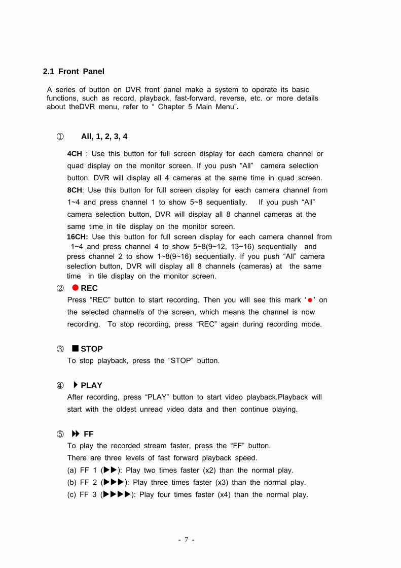
2.1 Front Panel
A series of button on DVR front panel make a system to operate its basic functions, such as record, playback, fast-forward, reverse, etc. or more details about theDVR menu, refer to “ Chapter 5 Main Menu”.
① � All, 1, 2, 3, 4
4CH : Use this button for full screen display for each camera channel or quad display on the monitor screen. If you push “All” camera selection button, DVR will display all 4 cameras at the same time in quad screen. 8CH: Use this button for full screen display for each camera channel from 1~4 and press channel 1 to show 5~8 sequentially. If you push “All” camera selection button, DVR will display all 8 channel cameras at the same time in tile display on the monitor screen. 16CH: Use this button for full screen display for each camera channel from 1~4 and press channel 4 to show 5~8(9~12, 13~16) sequentially and press channel 2 to show 1~8(9~16) sequentially. If you push “All” camera selection button, DVR will display all 8 channels (cameras) at the same time in tile display on the monitor screen.
② REC Press “REC” button to start recording. Then you will see this mark ‘ ’ on the selected channel/s of the screen, which means the channel is now recording. To stop recording, press “REC” again during recording mode.
③ STOP To stop playback, press the “STOP” button.
④ PLAY After recording, press “PLAY” button to start video playback.Playback will start with the oldest unread video data and then continue playing.
⑤ FF To play the recorded stream faster, press the “FF” button. There are three levels of fast forward playback speed.
(a) FF 1 ( ): Play two times faster (x2) than the normal play. (b) FF 2 ( ): Play three times faster (x3) than the normal play. (c) FF 3 ( ): Play four times faster (x4) than the normal play.

- 8 -
To change the fast forward play back speed level, press the “FF” button again.
⑥ REW To play the recorded stream backward, press the “REW” button. [NOTE]: The fast forward and reverse playback speeds will vary depending on the frame rate and record quality settings, as well as the number of channels recorded.
⑦ PAUSE To pause the video playback, press the “PAUSE” button. Then the video displaying will be stopped. To continue playback, push the play “PLAY” button.
⑧ Setup It displays menu option or go back to the previsou menu.
⑨ UP / DOWN
To change a menu field or change the DVR configuration values, use the “UP” or “DOWN” buttons.
⑩ SELECT
Use this button to change values on main menu or sub-menu setting.
⑪ ▂ Green LED Light
The DVR unit is powered up and running.
⑫ ▂Red LED Light
Hard disk drive is recording or reading.
⑬ IR Receiver Remote Controller is running.

- 9 -
⑭ Mobile Rack Mobile Rack for removable HDD or CD-RW/DVD-RW drive.
2.2 Rear Panel
1. POWER ON/ OFF SWITCH Use this button to turn on the DVR.
2. VIDEO OUT/ S-VIDEO OUT/ VGA Out Use this Video Out port to connect DVR to the CCTV monitor. Use this S-Video Out port to connect DVR to the TV set monitor. Use this VGA Out port to connect DVR to the computer monitor.
3. AUDIO IN & AUDIO OUT
1 2 2 23 4 5
6 10 7 8 9
11 5

- 10 -
Use “AUDIO IN” port for microphone connection and use “AUDIO OUT” port for speaker (mono) connect in.
4. CHANNEL in (VIDEO IN)
Use this BNC port to connect cameras to DVR system. You might need RCA adapter for each (CH1-CH8) camera connection.
5. LAN port/ USB port for 4, 8,16CH
The LAN port is for network connection between DVR and computer or router. The USB port is for the firmware upgrading and USB backup
6. PS/2 MOUSE PORT
Use this port for PS/2 mouse connection. If you have USB port mouse, use USB - PS/2 adapter to connect with this port.
7. SENSOR INPUT
You can use this sensor terminal block to install up to 4 motion sensors for 4CH DVR and 8 for 8CH into DVR. If you add the motion sensor devices to your DVR, the video recording can be triggered by motion detection.
8. ALARM (RELAY) OUTPUT
This is an alarm output terminal in case you need to attach an alarm device on the system.
9. RS485 SINGLE LINE TERMINAL
Use this terminal block for single line connection of PT camera.
10. AC-DC POWER ADAPTER JACK Connect the power adapter into DVR and plug the power cable into the wall. Some DVR models do not have a power adapter so you may not see this. In case, just plug power cable from the rear of the DVR into the wall.
11. USB MOUSE PORT for 16ch
Use this port for USB mouse connection.

- 11 -
2.3 Remote Controller (Option)
(for 4CH) (for 8CH) (for 16CH)
□ All DVR menu setting can be operated by either front panel buttons or remote controller.
□The functionality of each button both on remote controller and front panel is same.
□To stop recording during record mode, press “REC” button again. Then the
sytem will stop recording.

- 12 -
Chapter 3 Getting Started
Install a hard disk drive into your DVR. (Please refer to 4.1 for HDD installation and 4.1.1 for removable HDD installation) Connect DVR to monitor. (Please refer to 4.2 for monitor connection) Connect cameras to DVR. (Please refer to 4.3 for camera connection) Connect other peripheral devices (mouse, CD-RW/DVD-RW Drive, USB Drive, external motion sensors or alarm) if necessary. (Please refer to 4.4 & 4.5 for sensor & alarm connection) Plug the power cord into the power jack on the wall. Turn on the power switch of the back of the DVR. Start TV Monioring and Recording.
Make sure that a hard disk dirve and camera(s) are properly installed
The hard disk jumper setting must be set to “master “ jumper setting.
After installation of hard drive, the hard drive drawer must be locked with key, or the DVR will not recognize the hard drive.
If the power is turned off while recording (i.e. a power failure), the DVR will
enter “Power Recovery” mode at start up, detect that it has been shut down, and then reinitiate the recording process.

- 13 -
Chapter 4 Hardware Setup
4.1 Hard Disk Drive Installation (for Embedded)
Total max. capacity of HDD for DVR is 1TB(for 4,8ch) and 2T(for 16ch) , there is 8MB buffer no matter one or two HDDs have been installed.
Power off the DVR before HDD installation. Please make sure the Hard Disk Master and Slave jumper pin must be
correct, otherwis it makes DVR wor fault. (A) Make sure that HDD Jumper setting as “Master”
(B) Use the screw driver to remove the DVR cover to open the chassis.
(C) Connect the ribbon cable (IDE) cable & power cable
Before installing the hard drive, set jumper as “Master” (The master jumper setting varies depending on the hard drive manufactures. Refer to manufacture’s manual for master jumper setting.

- 14 -
(D) For IDE HDD:Plug in the IDE gray cable into the IDE connector of the main
board, and connect the HDD’s power cord. Please insert the HDD as shown in and set HDD Jumper setting as “Master” as Chassis A supports only one HDD.
For SATA HDD: Plug in the SATA gray cable into the SATA connector of the main board, and connect the HDD’s power cord. Chassis A supports only one HDD.
(E) After installing the HDD, slide in the chassis cover to replace the screw to fasten firmly.
4.2 Hard Disk Drive Installation (for Removable HDD)
Total maximal capacity of HDD for DVR is 1TB (for 4,8ch) and 2T (for 16ch); there is 8MB buffer no matter one or two HDDs have been installed.
Power off the DVR before HDD installation.

- 15 -
Please make sure the Hard Disk Master and Slave jumper pin already set up correct, otherwise it would make DVR work failed. (A) Plug out the mobile rack and install the removable HDD to fit in the rack,
connect the IDE gray cable to the slot of the rack and plug in the HDD’s power cord. If this removable HDD will be treated as master, please make sure the HDD Jumper setting as “Master” and the other HDD embedded in the chassis must set to be “slave” mode.
(B) Close the top cover of the rack and slide in the rack with HDD into your DVR firmly.
Before installing hard drive, set jumper as “Master” (The master jumper setting varies depending on the hard drive manufactures. Refer to manufacture’s manual for master jumper setting.
- 16 -
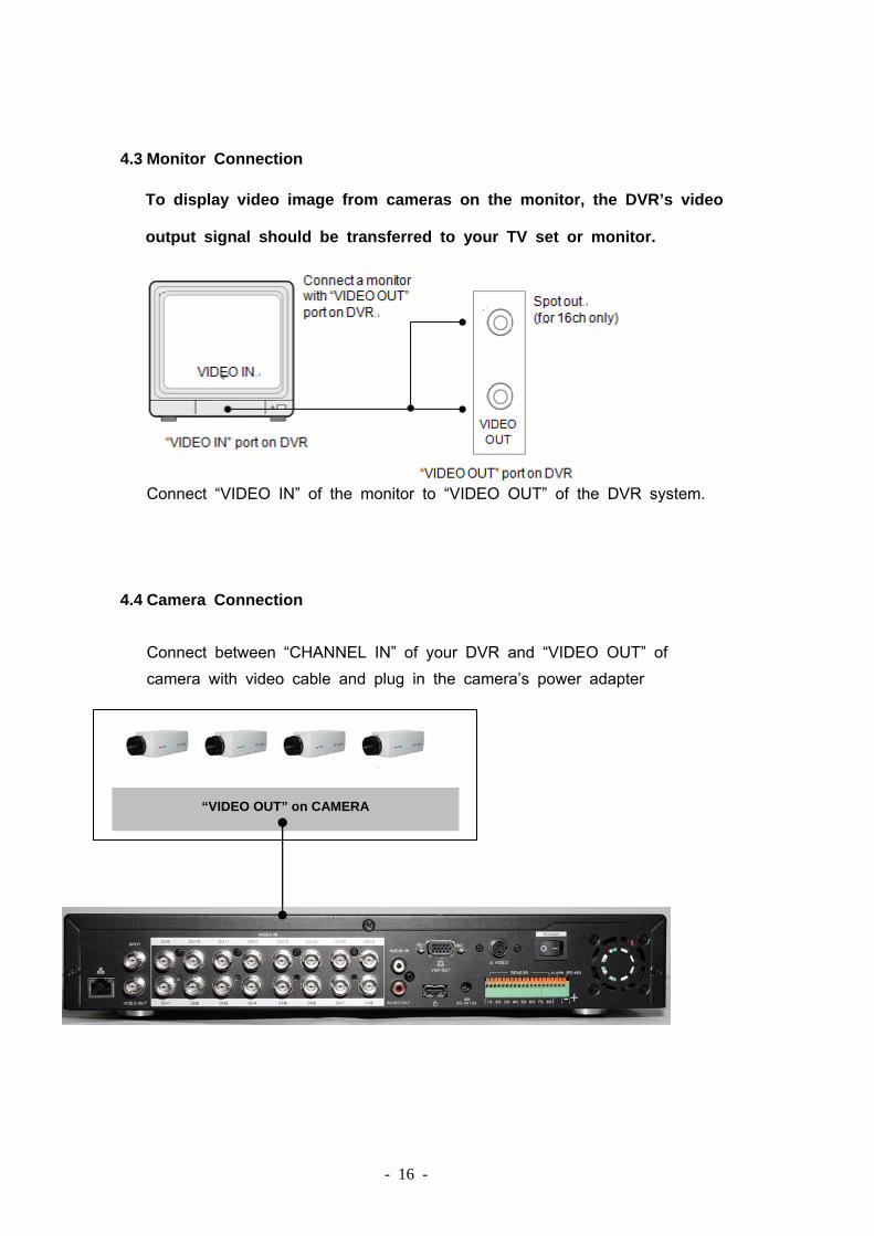
4.3 Monitor Connection To display video image from cameras on the monitor, the DVR’s video output signal should be transferred to your TV set or monitor.
Connect “VIDEO IN” of the monitor to “VIDEO OUT” of the DVR system.
4.4 Camera Connection Connect between “CHANNEL IN” of your DVR and “VIDEO OUT” of camera with video cable and plug in the camera’s power adapter
“VIDEO OUT” on CAMERA

- 17 -
4.5 Sensor Connection DVR can connect up to four sensos for 4ch DVR, 8 sensors for 8ch and 16ch.There are two steps for sensor in-stallation. (a) Connect the sensor signal lines to the signal input terminal. (b) Connect the sensor power lines to the appropriate power source. In general, there are three different types of sensors available in the homeelectrics store, where you can buy them. (1) Normal-Close (2) Normal-Open (3) Normal-Close & Open. Below is the brief diagram about how the each type of sensor is installed into DVR. The procedure for sensor installation is as shown below. * After you install sensor(s), change the recording mode as “S” on “RECORD SCHEDULE” in the DVR menu to enable sensor recording. * If the DVR system is in quad or tile mode and a sensor trips, all of the selected cameras will record. However, if you are in Each mode and a sensor trips, only the corresponding camera will record (i.e. sensor one corresponds with camera one).
(1) Normal-Close (2) Normal-Open (3) Normal Close & Open

- 18 -
4.6 Alarm Connection
The DVR has an internal switch for sounding alarm. The switch is normallyopen, but when the sensor is triggered, the alarm is activated as well. The circuitry is as follows. First, connect the alarm power lines to the alarm switch terminal.Second, connect the alarm power lines to the appropriate power source.
4.7 RS485 Singal Line Connection Use this port for RS485 Singal Line connection.
- + [RS485 Singal Line Terminal]
Power Adapter Alarm Device

- 19 -
4.8 Network Connection
Connect the LAN port with router for remote monitoring, recording,an dcontrolling DVR through internet or local area network. For direct connection with your computer and DVR,you need to use a cross-overcable. For conneciton with network hub, just use ordinary LAN cable.
[Ethernet Port]
4.9 Mouse Connection(4, 8ch) Connect PS/2 mouse with the port below on the sytem. If you have USB port mouse, use USB - PS/2 adapter to connect with this port. [PS/2 Mouse Port]
4.10 USB Port Connection Use this port for firmware upgrading and USB backup.
[USB Port]

- 20 -
USB Port Connection (for 16ch) Use this port for firmware upgrading and USB backup.
[USB Port]
4.11 DVR Power Connection
Connect a DVR power adapter to the adapter jack at the rear panel of DVR unit And turn the power switch on. It will boot up the system. If you install a new hard disk drive, it will ask for HDD formatting before a system starts to run. Choose format option pressing “PLAY” button.
4.12 Power on the DVR
After the DVR is properly installed, the DVR is ready to record and play. Then apply power and switch on. After the DVR is powered on, the DVRwill check HDD for several seconds, and then DVR will enter into real-time display mode shown as the following screen:

- 21 -
Chapter 5 Main Menu After installing a new hard drive on the system, press “PLAY” button to format the hard drive first. After system boot-up, press the MENU button to make any changes of DVR settings. You will see the screen below on the monitor.
You must enter a password first, the default password is”111111”

- 22 -
Press the “UP” or “DOWN” key on the DVR front panel or remote controller to move the cursor “►” . Press “SELECT” button on the front panel or remote controller in order to change the settings. In the MAIN MENU, the cursor “►” will be shown on the screen right next to each sub menu.
To go back to the previous menu, press “MENU” button on the front panel or remote controller. 5.1 Enabling Triplex Functionality
Use these buttons in sequence for simultanenous record, playback, and network. REC Playback By doing this, the system can playback, record, and external media backup (CD-RW/ DVD-RW USB) and network at the same time.
5.2 Camera
Use this option for video color adjustment for each channel. Go to DISPLAY option to enable or disable for screen display of each camera.

- 23 -
Video lose The Standalone DVR will beep by buzzer on main board or beep by relay of system when video loss. There are intermittent and continuous for alarm duration,and you can setup off、buzzer、alarm device(relay) for your require。
5.3 Record
Use this option to choose the channel for recording. Only selected channel will be recorded no matter how many camera channel are displayed on the screen. (Caution: Press “REC” button again and type password to stop manual recording)
[Resolution] You can set it as 640*224 or 320*224 (for 16ch only)

- 24 -
[RECORD Speed] Change the record speed for each channel. The higher the record frame,the more natural movement you will see while playback Independent each channel frame rate adjustment is possible. Press channel button 4 to increase the record frame rate for each channel. Press channel button 2 to decrease the record framerate for each channel. If you make the record speed off, the channel won’t record.
[ RECORD QUALITY] Chose record quality among LOW / NORMAL/ HIGH. The higher the record quality, the higher the video image quality while you playback. [EVENT RECORD DURATION] Using SELECT button, adjust the alarm duration time (5-30 seconds) when an alarm device goes off.

- 25 -
[RECORD SCHEDULE]
The numbers below indicate the hours of the day based on a 24-hour clock. The first
“T” equals the first hour of the day (Midnight - 1:00 am).
(--) No recording during this time period. (T) The system will continuously record unless the user disables the recording
schedule. (M) The sensor recording will be activated by the built-in motion sensor of the system. (See also the following chapter “ MOTION DETECTION”) (S) It will activate the sensor recording during this time of period. (The sensor device should be installed to enable this type of recording)
** The combination of these four types of record schedule also possible.
(M+S) The motion record and sensor record work simultaneously
5.4 Sensor Sensor detection It will beep by buzzer on main board or beep by relay of system when sensor detection.,you can setup buzzer or alarm device (relay) for your requirement. 16ch support 8 sensors only..
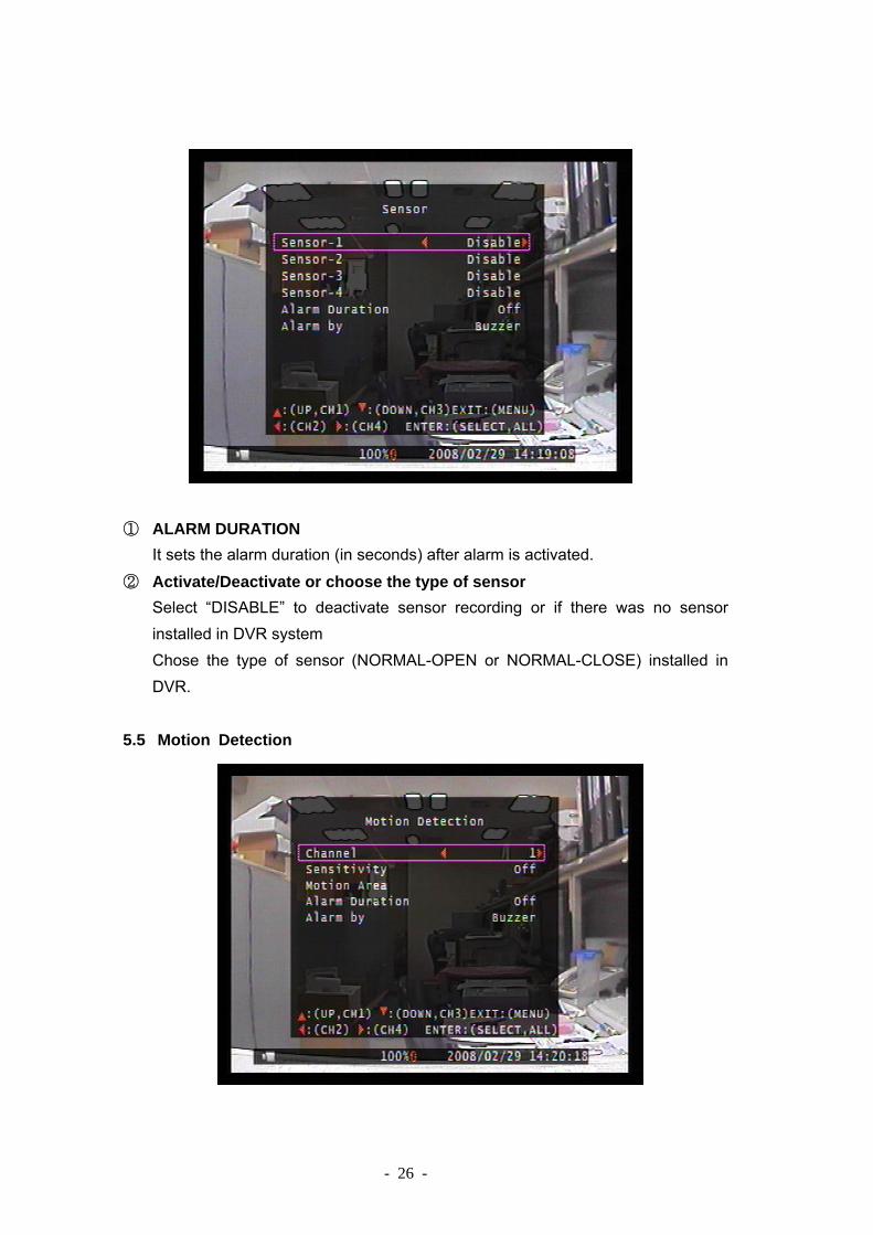
- 26 -
① ALARM DURATION It sets the alarm duration (in seconds) after alarm is activated.
② Activate/Deactivate or choose the type of sensor Select “DISABLE” to deactivate sensor recording or if there was no sensor installed in DVR system Chose the type of sensor (NORMAL-OPEN or NORMAL-CLOSE) installed in DVR.
5.5 Motion Detection

- 27 -
[CHANNEL] Select the channel (1~16) for recording mode by internal motion sensor. [SENSITIVITY] It adjusts the sensitivity of the built-in motion sensor on the DVR system while recording. The maximum sensitivity level is 4. [MOTION AREA ] Use this option to select the range of motion detection area. Use the keypad button, remote control button, or mouse click to assign the area. The keypad and mouse control instructions are below. [ Using keypad or remote control button ]
* ALL : Select or deselect the motion detection area
: Up / ch2: Left / : Down / ch4: Right [ Using Mouse button ]
While holding a left mouse click button, move the mouse to select, deselect, or reselect the motion detection area for recording.
[ALARM DURATION]
It will beep by buzzer on main board or beep by relay of system when motion detection.,you can setup buzzer or alarm device (relay) for your require。
5.6 Screen

- 28 -
[BORDER] You can make the white border line around each channel to appear or disappear by using this option to be on or off. [VIDEO ADJUSTMENT] You can move the entire video screen up, down, left, and right using this option. [Auto sequence] To setup how long to display each channel on full screen from 2~30sec. 5.7 Audio
Make the record “ON” to enable sound recording when a miccrophone device
- 29 -
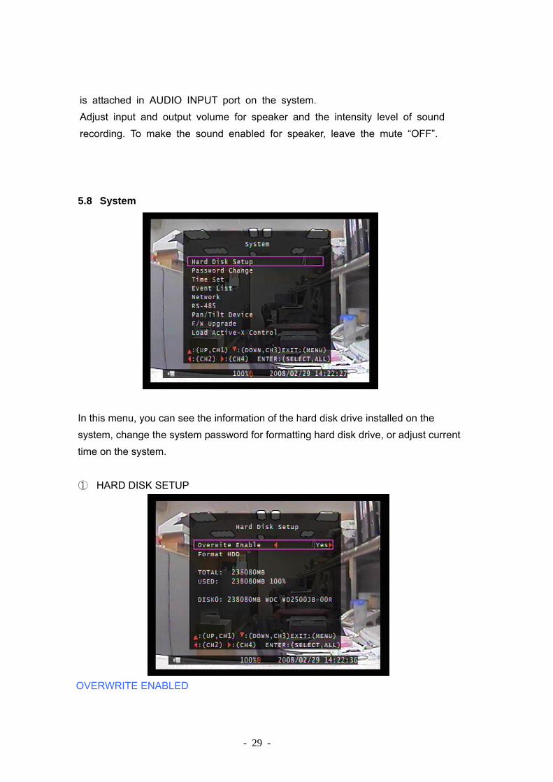
is attached in AUDIO INPUT port on the system. Adjust input and output volume for speaker and the intensity level of sound recording. To make the sound enabled for speaker, leave the mute “OFF”. 5.8 System
In this menu, you can see the information of the hard disk drive installed on the system, change the system password for formatting hard disk drive, or adjust current time on the system.
① HARD DISK SETUP
OVERWRITE ENABLED
- 30 -
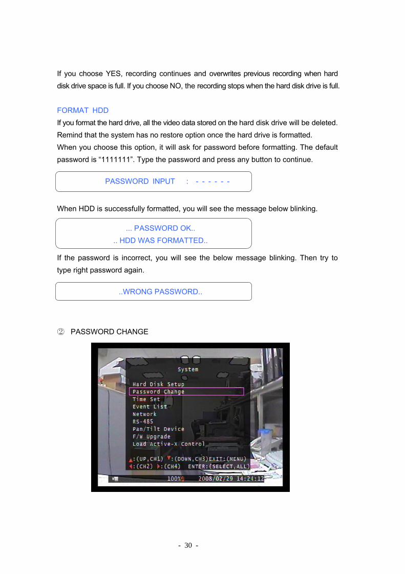
If you choose YES, recording continues and overwrites previous recording when hard disk drive space is full. If you choose NO, the recording stops when the hard disk drive is full. FORMAT HDD If you format the hard drive, all the video data stored on the hard disk drive will be deleted. Remind that the system has no restore option once the hard drive is formatted. When you choose this option, it will ask for password before formatting. The default password is “1111111”. Type the password and press any button to continue.
When HDD is successfully formatted, you will see the message below blinking. If the password is incorrect, you will see the below message blinking. Then try to type right password again.
② PASSWORD CHANGE
PASSWORD INPUT : - - - - - -
... P ASSWORD OK.. .. HDD WAS FORMATTED..
..WRONG PASSWORD..

- 31 -
You can change password for “Menu”、”Record”、”Format HDD” ,The default
password is 111111. The number corresponds with the number button for camera channel. For example, in order to input a numeric value “2”, press the channel number “2” button on DVR front panel. You can use a combination of any of the buttons on the DVR front panel to set a new password.
③ TIME SET You can adjust the current time, date, and year at any time by region. Set your region first and set the current time so that the video back-up data can be played without time shifting later on.
Date and Time format are below. *** 2008/02/29 = year/month/day *** 14:24:40 = hour : minute : second

- 32 -
To move the cursor on the screen, use “UP” and “DOWN” key on the DVR front panel and then press “SELECT” button to change the numeric value. Once you finish time setting, press “MENU” button. Then press “DOWN” key and “SELECT” button to apply the new time set.
④ EVENT LIST
EVENT LIST function enables playback by event. On the EVEN LIST menu, it shows all past activities of system operation such as power on/off, recording start/stop, sensor on/off and etc showing recording year/date/time in list.
To playback by EVEN LIST, using UP/DOWN or channel number (1 for UP or 3 for DOWN) key, select the event that you want to playback and press “PLAY” button. Then, the recording video data will be playback.
⑤ NETWORK

- 33 -
You need to use the network setting information above for real-time network viewing on PC using “Triplex Viewer” software for remote viewing through Ethernet connection. [Note] You’d need to use different IP address from DVR’s on TCP/IP setting under Windows operating system. However, type the same password on DVR when you remotely connect to DVR for PC software setting. There three different network connection types, which are supported by our DVR system.
1. STATIC 2. DHCP for dynamic IP. 3. PPPoE
You can choose either one of them above depending your network environment and make the remote monitoring, recording, and controlling through network connection to DVR.
⑥ RS485
Adjust the RS485 setting depending on the PT camera.
⑦ PAN/TILT DEVICE

- 34 -
[CHANNEL] Select a camera channel where PT camera is connected. To change channel umber, use number “4” and “2” button on keypad. [ID ] Assign the ID number of PT camera (The ID number can be found on the back of the camera). To increase the ID number, press number “4” key and decrease ID Number – Press number “2” key [MODEL] Currently, our system supports PELCO D and LI-LIN camera
[PAN/TILT TEST] You can control Pan and Tilt operation of PT camera (4, 8ch) or PTZ camera (16ch)
You can use PTZ function in Liveview mode(for 16ch only), In full screen on Liveview mode, if you press PAUSE key , the DVR go to PTZ control mode, In this mode, you can select functions like ZOOM, IRIS, FOCUS, MOVE with pressing SELECT key. And you can send commands with press CH1~4 key. If you press PAUSE again, the DVR will go to Live view mode
⑧ F/W UPGRADE This menu is for firmware upgrade of DVR system through USB host (USB flash disk) connection, you can simply upgrade the system once you connect the USB flash disk that contains a firmware file. [CAUTION ] Do not turn off the system while the system is upgrading. Otherwise, it will cause the breakdown of the system that needs to send back the DVR for a special recovery process.

- 35 -
9 Load Active-X Control Load “ Active-X Control” Driver from IE browse or CD to remote surveillance control on PC, IE security settings should be set to the default levels to allow the download of the control.
NOTE: Firewalls or other security programs/ devices may prevent downloading the Active-X control.

- 36 -
5.9 Language DVR supports multi-language OSD. You can choose the language you need for display menu on the screen. You can change it by pushing “SELECT” button on “LANGUAGE”.
5.10 Exit After you change setting on DVR menu, you need to confirm the changes under EXIT menu.

- 37 -
Chapter 6 Playback with Time Search Function
This is an enhanced playback option, which enables the user manually to adjust a specific starting time for playback. In order to playback with time search function, press "PLAY” button first. And then press “SELECT” key to change the value of the playback start date & time and press “PLAY” button again. The playback will start from the date & time indicated by the user.

- 38 -
Chapter 7 Backup via USB flash disk or internal CD-RW/ DVD-RW Drive
DVR has an enhanced backup feature so that it’s possible to transfer the video data image recorded on the hard drive to USB flash disk or internal CD- RW. Before you back up a stream of video data, have the USB flash disk to be ready and attach them into DVR system.
1. In order to save the video data with these backup devices, you should first
start with playback. And then press “MENU” button. Use “UP” key to set start time and “DOWN” key to the end time of the recorded video data, which will be saved in backup devices.
2. Press “SELECT” button to back up the video data on USB flash disk.
It will take a few minutes to write the video data on USB flash disk. The file size number is going up until it’s done with the message below. WRITING… Then it will show the following message on the screen. FIXATING… Take out the USB flash disk and attach it into your PC when it’s done.

- 39 -
3. Press “REC” button to back up the video data on CD First,you must stop all record state when star to back up CD
Following the above USB backup process, but finally press “ REC” button to copy the video data on CD. When it’s done, the CD will pop pout from the CD-RW/DVD- RW drive. Take out the CD and insert it in the CD-RW/DVD-RW driver on your computer. Press “ Menu” button to exit OSD menu to real-time display.
4. To view the video image saved on back-up devices on the computer, you need our client software provided in the software CD. After playback, press “MENU” button. Then using “UP” and “DOWN” key, set the time period of recorded video data that you want to save on the back-up devices.

- 40 -
Chapter 8 Player & Viewer
DVR comes with one software CD for remote monitoring, recording, DVR controlling or playback of backup video data on computer.
8.1 Player 8.1.1 Menu Description
[Main Menu on Player option]
Player: It is for playback of the video data (VVF format) that has been saved on PC.
Netviewer: The software will be switch to NetViewer Option for network connection between PC and DVR
Open File: Select the file (VVF format) to playback video file on computer Open Disk: Select this option to read the video data of the hard disk drive,
which is used for recording on DVR. [Note] To use this option, the hard drive used on DVR should be taken out first and attach it to computer via USB or IDE connection.
- 41 -
Export: Convert the VVF format of video data as AVI format to playback using standard MPEG player such as Windows Media Player.
Close: Close down Viewer. Show Time: Make the record year/date/time/seconds on or off on the
viewer screen while playback. Always On Top: Make the display screen on top all the time or make it off. Playback: Make different setting for playback such reverse playback, fast
forward, rewind, speed up/down, or show still video image by single frame. Capture: When you click this button while playback mode, it create a single
BMP file (image file like JPEG) and automatically save the video image on your PC. (Default file saving directory: C:\VxCapture)
Audio: You can make the audio volume up or down or make it mute. Full Screen: Make the video image full on the monitor. Maximize: Maximize the screen image. You still can see the control button
icon at the bottoms. Aspect Ratio: Change the display ration either between 640X448 and
640x554. Split Mode: Choose “Split 1” for full screen display of each channel. Chose
“split 4” for quad (4 -channel) display mode. Options: You can change some general settings such as DDNS
configuration, change the directory for saving the screen shot data (BMP format), etc.
About Viewer: It shows the version number. Exit: Exit viewer.
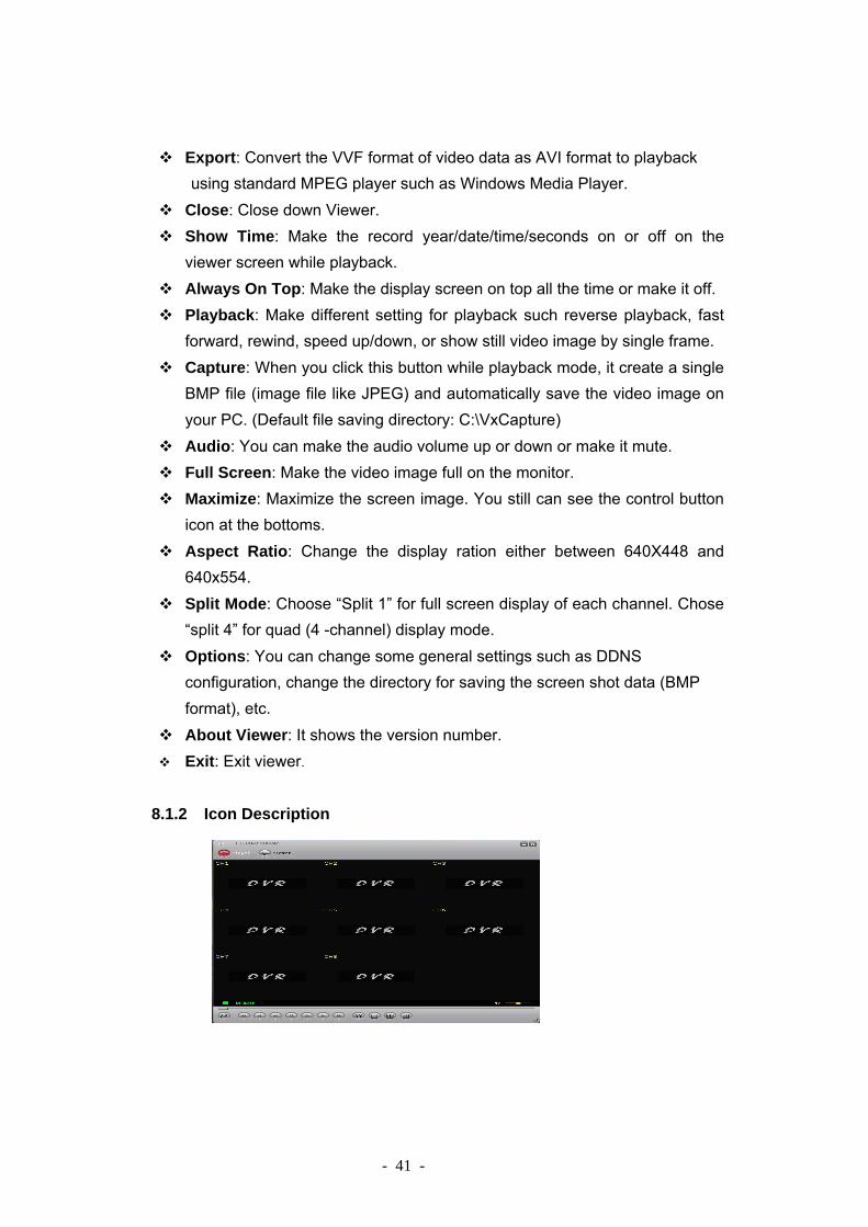
8.1.2 Icon Description

- 42 -
Use a mouse and click a list of icons at the bottom to window for different functionalities. [Icons]
8.1.3 Playback with Saved Video Data
After saving the video images on back-up devices, you may want to view the video stream image on PC. In order to do that, please follow the instruction below. a. Connect the USB flash disk to your PC or insert the back-up CD
into the CD/ DVD driver on computer.
Open and play saved video stream file
Go one frame backward and PAUSE
Pause
Playback
When you click this button, it will take a single frame of video image while playback and then it will automatically the image (BMP format) into the local PC directory. (Default Directory: “C:\DVRCapture”)
View in full screen mode
View in 4-channel screen mode
Adjust volume or enable speaker sound ON/OFF
Play Reverse
Rewind
Fast Forward
Go one frame forward and PAUSE
- 43 -
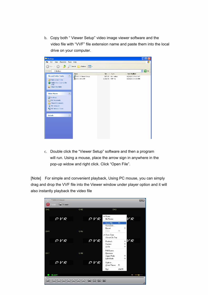
b. Copy both “ Viewer Setup” video image viewer software and the video file with “VVF” file extension name and paste them into the local drive on your computer.
c. Double click the “Viewer Setup” software and then a program will run. Using a mouse, place the arrow sign in anywhere in the pop-up widow and right click. Click “Open File”.
[Note] For simple and convenient playback, Using PC mouse, you can simply drag and drop the VVF file into the Viewer window under player option and it will also instantly playback the video file

- 44 -
d. Select the video image file which has been saved in USB e. Open up the file and it will show a stream of video image on your computer monitor.

- 45 -
8.1.4 Convert Video Stream as Standard AVI Format You can convert the existing backup file as AVI format to view with standard MPEG-4 player or windows media player. (1) Click Player > Export > AVI (Audio-Video Interleaved Files)
(2) Click “Browse” under “Input File” and select the file that you want to convert into AVI format.

- 46 -
(3) Click “Browse” and select the file that you want to convert into AVI format and click “Open”.
(4) Click “Browse” under Output File and select the directory where you want to save and name the file. And then “Select” for compression.

- 47 -
(5) Click “Select” and then select the type of convert format for compression.
(6) Click “OK”. Then it will take few minutes to convert. (7) Go to the directory where you’ve just saved AVI file and open the file with standard media player. We recommend GOM player when you play it back.
8.2 NetViewer Option for DVR Connection via Network Open up viewer and click “Viewer” option for remote monitoring, remote DVR controlling, and recording either on PC or DVR. 8.2.1 Menu Description
[Main Menu on NetViewer option]
- 48 -
Player: It is for playback of the video data (VVF format) that has been saved on PC.
Netviewer: The software will be switch to NetViewer Option for network connection between PC and DVR
Connect: Connect the DVR via network either via DHCP or Static. [Note: See next section for detail.]
DVR Control: You can control DVR operation remotely using this option. After network connection is made, all DVR controls can be made remotely via network.
Audio: You can make the audio volume up or down or make the sound off. Local Recording: Click “Star Local Recording” and it will start video
recording (VVF format) on your local PC. The default directory for saving is “C:\VxCapture”. Click “Stop Local Recording” when you want to stop recording the video on PC’s hard drive.
Always On Top: Make the display screen on top all the time or make it off. Full Screen: Make the video image full on the monitor. Maximize: Maximize the screen image. You still can see the control button
icon at the bottoms. Aspect Ratio: Change the display ration either between 640X448 and
640x544. Options: You can change some general settings such as DDNS
configuration, change the directory for saving the screen shot data (BMP format), etc. Check “Auto Reconnection” box and then it will automatically make the viewer to reconnect to DVR via network when the system reboot or physical connection line is plug in again.
About Viewer: It shows the version number. Exit: Close viewer program.

- 49 -
(1) DVR – PC connection through local area network (netowrk hub) <Step 1> Run Viewer and click “NetViewer” on toolbar. Then click “Connect” (Player is for viewing back-up video data on PC)
<Step 2> Type IP address (the same IP address on DVR) and password
(You can find the password on “Network Settings” MENU on DVR – Default Password: 111111). Then click “Login”.

- 50 -
(2) DVR – PC direct connection through cross-over cable. (A) Using cross-over cable connection between DVR and PC.
You might need to change TCP/IP setting under winows operating systems for direct cross-over cable connection between DVR and PC. Let’s suppose that your DVR IP setting are below.
Then, you also need to change the TCP/IP setting under XP windows operating system shown below. <Step 1> Go to TCP/IP setting under Local Area Connection Properties On Windows XP operating system.

- 51 -
<Step 2> Type the numeric the value under IP address/Subnet mask/ Default gateway setting according to DVR IP settings. The IP address should be the different from the one on DVR. Others should remain same on DVR settting. Leave the DNS server blank unless it’s necessary.
<Step 3> Click “OK” and run Viewer.

- 52 -
Type IP address (same IP address of DVR) and Password (Default Password: 111111). [Note] Type DVR ID for connection through Dynamic IP service).
Once you connect, you will see DVR monitor screen on your PC.
8.3 Install and Set up the Remote Surveillance from IE Browser (A) Install Active-X Control component
Please insert the DVR CD into CD-ROM, and also insert USB pen Driver to PC for backup, then copy the file “VXVSETUP.EXE” to USB pen driver from the folder of Active-X Control \4CH or 8CH DVR.
(B) Connect “USB pen driver“ to DVR USB Port

- 53 -
(C) Stop DVR all record status first then Press “Setup” option of DVR, then select “System” and enter “Load Active-X control”
(D) If it appears “USB Device is not exist” message that means USB pen driver is not connected to DVR well. Please insert again as process 8.3.2.
(E) If it appears the follwing message, please press “Paly“ button, then install
“Active-X component” to DVR

- 54 -
(F) Install “VXVSETUP.EXE” to PC Input DVR’s IP Address: [192.168.1.100] to URL as http://192.168.1.100 (The IP address is for the reference)
Please install this file to download “ VXVSETUP.EXE” if you can’t see a back black box as below:
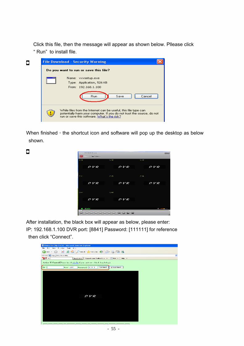
- 55 -
Click this file, then the message will appear as shown below. Pllease click “ Run” to install file.
�
When finished,the shortcut icon and software will pop up the desktop as below shown.
�
After installation, the black box will appear as below, please enter: IP: 192.168.1.100 DVR port: [8841] Password: [111111] for reference then click “Connect”.

- 56 -
While browsing, you can remote configure the DVR on you IE broswer

- 57 -
Why using DDNS, you must know: If you’re using dynamic IP from your ISP, or you have a demo room for your customer. Those complicated IP address is hardly to be remembered. So under the situation, DDNS brings much convenience for you / your customer to remember easily where your DVR’s location is, and connect to your DVR via IE browser or specified program at anytime and anywhere.
【PART I】Domain name application 1. Link to http://www.dyndns.com/services and ask an account for DDNS service
application.
2.Enter your relative information in this page,

- 58 -

- 59 -
3.Account created successful
4.Click the URL in your instant mail after registration to ensure your account taking effect.
5.Login with Account ID and Password at 2nd step.

- 60 -
6.Click the page’s ultra-link as following sequence.

- 61 -
7.Add new hostname
8.Enter the hostname corresponding to the IP address assigned from your ISP. If you have multiple IP from your ISP, input any one of them, the IP will be available automatically. (CAUTION: We strongly recommend the hostname definition no longer than 20 characters )

- 62 -
9.So far, we’ve already finished DDNS application.
10.Test whether the DDNS resolution success or not by ICMP protocol. Ping the hostname defined on DynDNS’s web site for verification.

- 63 -
【PART II】DVR Network configuration
Login DVR’s menu and directly enter to Network setting. <PATH> Menu >> System >> Network <OPTION> Enable YES
Enter to Local IP to select IP type (depend upon your ISP) <PATH> Menu >> System >> Network >> Local IP
Variant types for you selections to be compatible to your network environment. (1) Static IP
<OPTION>
IP address necessary information
Gateway necessary information

- 64 -
Net Mask necessary information
(If lack of the above information, please contact to your ISP)
(2) DHCP
Select this function, then save and exit.
It will detect available IP address from your DHCP server after reboot DVR.
(3) PPPoE
Relative information available from your ISP, please input them when using this
function.(including PPPoE ID & Password)

- 65 -
【PART III】DVR DDNS configuration
1. Login DVR’s menu and directly to DDNS setting. <PATH> Menu >> System >> Network >> DDNS setting <OPTION> Enable YES DNS IP ADDRESS Available automatically after booting DVR URL The hostname applied from DDNS supplier (For example: xcore-dvr.dyndns.org) User ID ID applied when login to DDNS supplier’s web Password Password applied when login to DDNS supplier’s web
After completing above configuration, DDNS setting finished.
2. Now, you can login Triplex Viewer (Please confirm Triplex Viewer installed first) and start to use with typing your favorite hostname.
.

- 66 -
How to set up 2 DVRs under the same router for DDNS: 1. First of all, connect these 2 DVRs to the same router and we can name them
as DVR1 & DVR2.
2. Difference of setup between DVR1 & DVR2: a. Local IP:while selecting DHCP, 192.168.1.XXX (this is allocated by router
so the no. will be different) b. Port:DVR1 set as 8841, DVR2 set as 8842 (you may change as you need
but these 2 DVRs should be set as different port no.) c. Mac address:DVR1 set as 12:34:56:78:9A:BC (default), DVR2 set as
12:34:56:78:9A:BD (this can be changed but should be different from DVR1.) d. After set up, you may check whether you can see from the DHCP Client List
or not. (the layout of the DHCP Client List may be varied to different router, but the function should be more or less the same.)
Picture shown as above, you'll see there're 2 DVRs in the list. If there're more than 2 DVRs, you may analogize with the same setup.
3. Then, enter the selection of NAT in router to set up the port of DVR1 & DVR2 to a designated IP of DVR in virtual server. The designated IP of the port 80
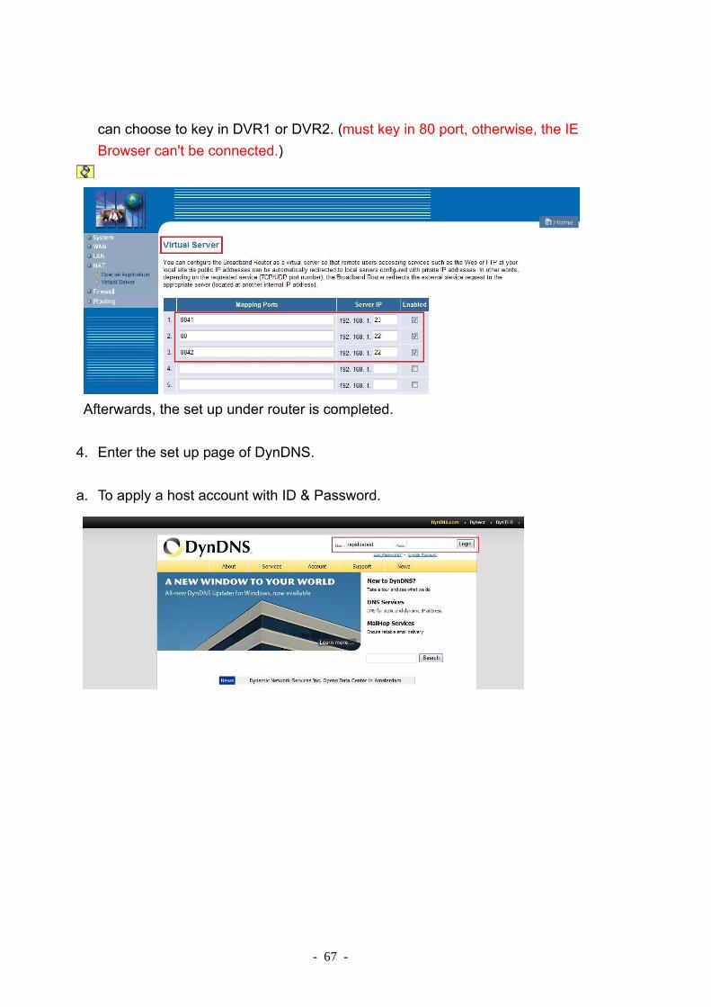
- 67 -
can choose to key in DVR1 or DVR2. (must key in 80 port, otherwise, the IE Browser can't be connected.)
Afterwards, the set up under router is completed.
4. Enter the set up page of DynDNS.
a. To apply a host account with ID & Password.
- 68 -
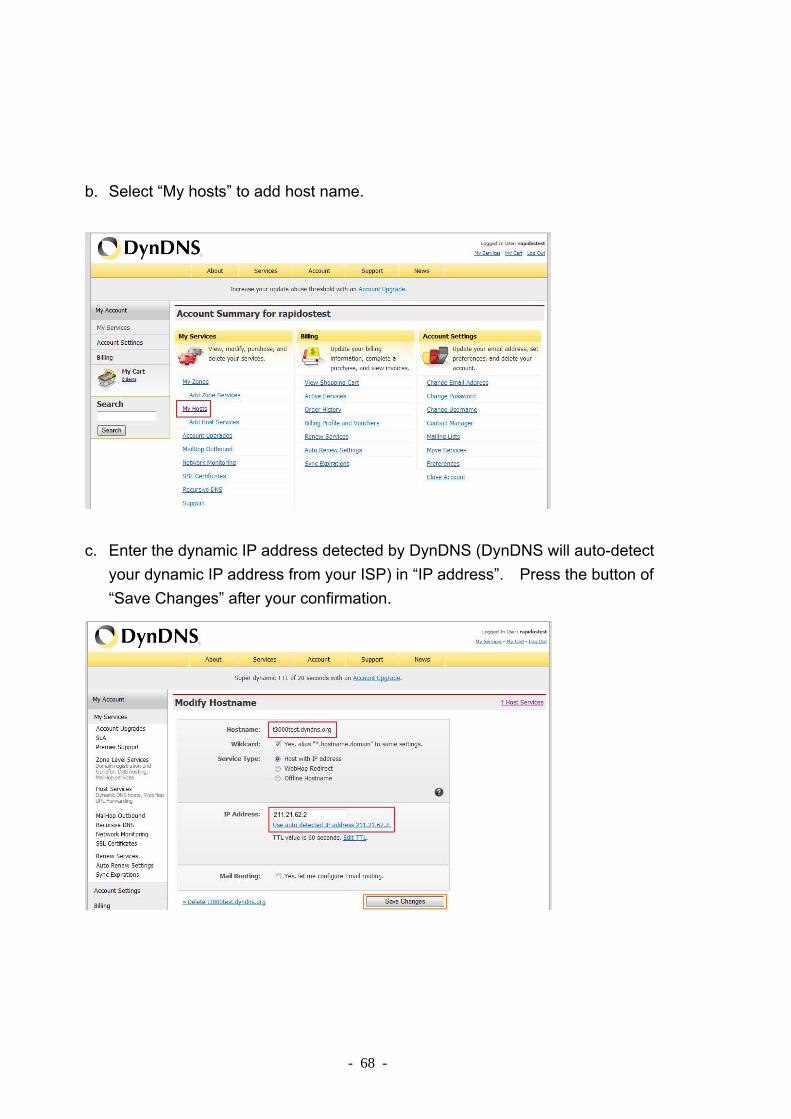
b. Select “My hosts” to add host name.
c. Enter the dynamic IP address detected by DynDNS (DynDNS will auto-detect
your dynamic IP address from your ISP) in “IP address”. Press the button of “Save Changes” after your confirmation.
- 69 -
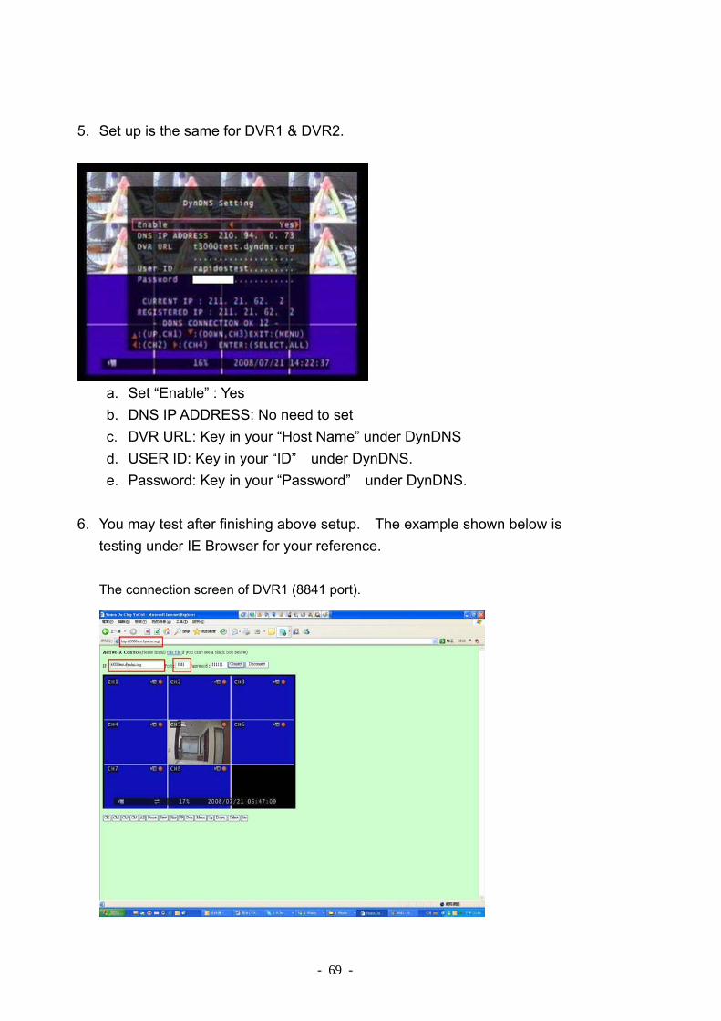
5. Set up is the same for DVR1 & DVR2.
a. Set “Enable” : Yes b. DNS IP ADDRESS: No need to set c. DVR URL: Key in your “Host Name” under DynDNS d. USER ID: Key in your “ID” under DynDNS. e. Password: Key in your “Password” under DynDNS.
6. You may test after finishing above setup. The example shown below is
testing under IE Browser for your reference. The connection screen of DVR1 (8841 port).

- 70 -
The connection screen of DVR2 (8842 port).
The connection screen by using Client Software.
The connection screen of DVR1 (8841 port).

- 71 -
- 72 -
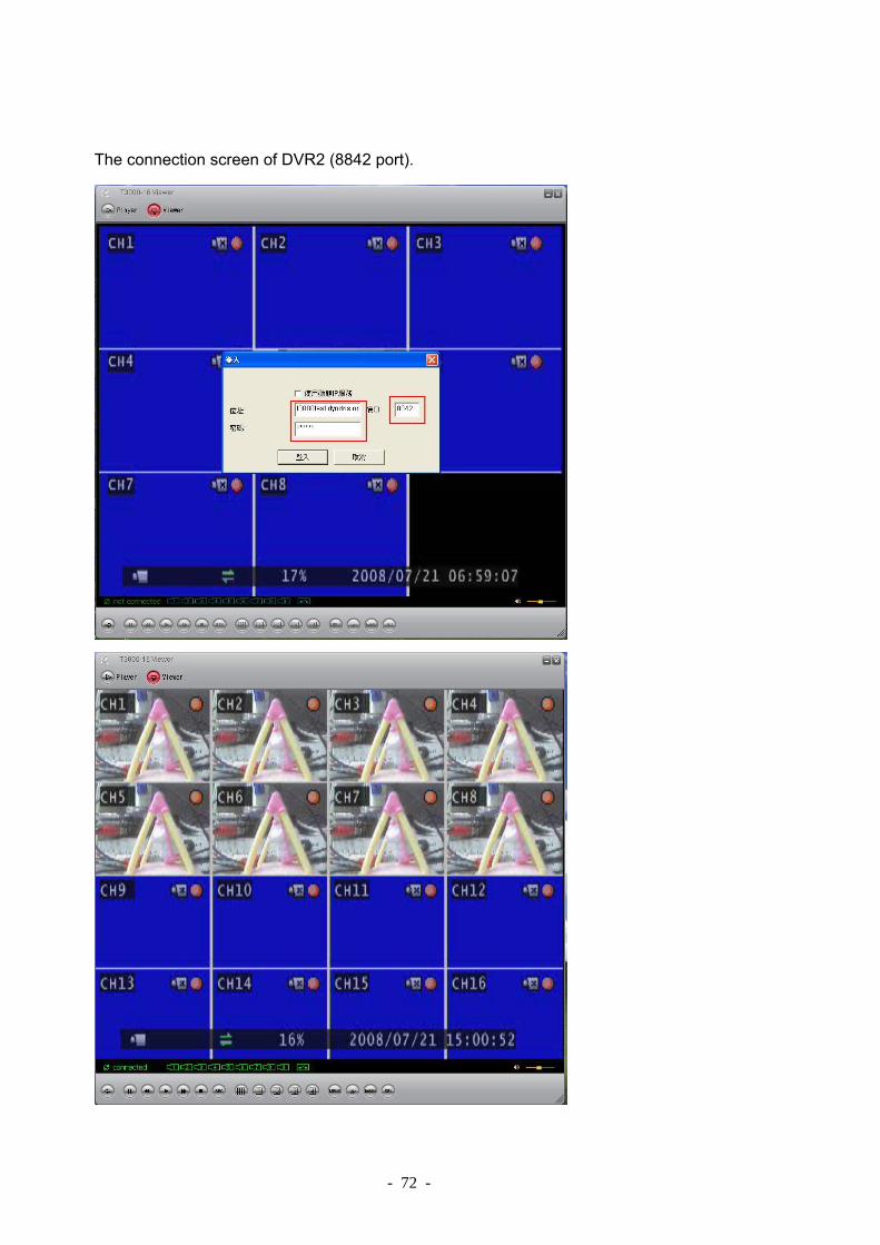
The connection screen of DVR2 (8842 port).

- 73 -
Appendix-Record Time Table
The recording hours is based on 250GB HDD for 4-Channel NTSC Format Frame/ Second
1 2 3 4 5 7 10 15 30
High 910 455 303 228 182 130 91 61 30
Mode Normal 1214 607 405 303 243 173 121 81 40
Low 3641 1820 1214 910 728 520 364 243 121 (By: Hours)
PAL Format Frame/ Second
1 2 3 4 6 8 12 25
High 910 455 303 228 152 114 76 36
Mode Normal 1214 607 405 303 202 152 101 49
Low 3641 1820 1214 910 607 455 303 146 (By: Hours)
The recording hours is based on 500GB HDD for 16-Channel [NTSC Format] (By: Hours)
Frame/ Second 1 2 3 4 5 7
MODE
High 455 228 152 114 91 65
Normal 607 303 202 152 121 87
Low 1820 910 607 455 364 260
[PAL Format] (By: Hours)
Frame/ Second 1 2 3 4 5 6
MODE
High 455 228 152 114 91 76
Normal 607 303 202 152 121 101
Low 1820 910 607 455 364 303


![Dali Dvr - User's Manual v1[1].1](https://static.fdocuments.us/doc/165x107/5477b1acb4af9f58108b495a/dali-dvr-users-manual-v111.jpg)