DV Gas Fireplace Heater 530ILN/ILP (logs), 530ICN/ICP ... Title PDF manuals/English/530... · DV...
48
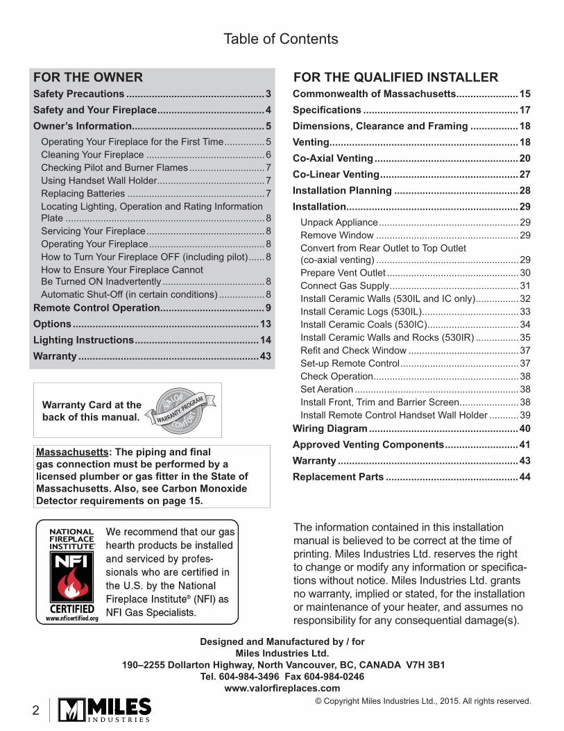
4001754-21 P ORTRAIT Installation & Owner’s Manual This manual contains instructions to install the EN- GINE ONLY. A front trim kit is REQUIRED to install the engine as it affects the framing cavity and posi- tion of the engine. A barrier screen is provided with the front or trim kit. Refer to the manual supplied with the front for framing and finishing. — Do not store or use gasoline or other flammable vapors and liquids in the vicinity of this or any other appliance. — WHAT TO DO IF YOU SMELL GAS ▪ Do not try to light any appliance. ▪ Do not touch any electrical switch; do not use any phone in your building. ▪ Leave the building immediately. ▪ Immediately call your gas supplier from a neighbor’s phone. Follow the gas supplier’s instructions. ▪ If you cannot reach your gas supplier, call the fire department. — Installation and service must be performed by a qualified installer, service agency or the gas supplier. Ce guide est disponible en français sur demande. This appliance is only for use with the type of gas indicated on the rating plate. This appliance is not convertible for use with other gases, unless a certified kit is used. This appliance is a domestic room-heating appliance. It must not be used for any other purposes such as drying clothes, etc. This appliance is suitable for installation in a bedroom or bed sitting room. This appliance may be installed in an after-market permanently located, manufactured (mobile) home where not prohibited by local codes. HOT GLASS WILL CAUSE BURNS. DO NOT TOUCH GLASS UNTIL COOLED. NEVER ALLOW CHILDREN TO TOUCH GLASS. DANGER ! A barrier designed to reduce the risk of burns from the hot viewing glass is provided with this appliance and shall be installed for the protection of children and other at-risk individuals. ! WARNING FIRE OR EXPLOSION HAZARD Failure to follow safety warnings exactly could result in serious injury, death, or property damage. INSTALLER Leave this manual with the appliance. CONSUMER Retain this manual for future reference. Please read this manual BEFORE installing and operating this appliance. DV Gas Fireplace Heater 530ILN/ILP (logs), 530ICN/ICP (coals), 530IRN/IRP (rocks) ©2015, Miles Industries Ltd. All rights reserved.
Transcript of DV Gas Fireplace Heater 530ILN/ILP (logs), 530ICN/ICP ... Title PDF manuals/English/530... · DV...
4001754-21
PORTRAIT
Installation & Owner’s Manual
This manual contains instructions to install the EN-GINE ONLY. A front trim kit is REQUIRED to install the engine as it affects the framing cavity and posi-tion of the engine. A barrier screen is provided with the front or trim kit. Refer to the manual supplied with the front for framing and fi nishing.
— Do not store or use gasoline or other fl ammable vapors and liquids in the vicinity of this or any other appliance.
— WHAT TO DO IF YOU SMELL GAS ▪ Do not try to light any appliance. ▪ Do not touch any electrical switch; do
not use any phone in your building. ▪ Leave the building immediately. ▪ Immediately call your gas supplier from
a neighbor’s phone. Follow the gas supplier’s instructions.
▪ If you cannot reach your gas supplier, call the fi re department.
— Installation and service must be performed by a qualifi ed installer, service agency or the gas supplier.
Ce guide est disponible en français sur demande.
This appliance is only for use with the type of gas indicated on the rating plate. This appliance is not convertible for use with other gases, unless a certifi ed kit is used.This appliance is a domestic room-heating appliance. It must not be used for any other purposes such as drying clothes, etc.This appliance is suitable for installation in a bedroom or bed sitting room.
This appliance may be installed in an after-market permanently located, manufactured (mobile) home where not prohibited by local codes.
HOT GLASS WILL CAUSE BURNS.
DO NOT TOUCH GLASS UNTIL COOLED.
NEVER ALLOW CHILDREN TO TOUCH GLASS.
DANGER!
A barrier designed to reduce the risk of burns from the hot viewing glass is provided with this appliance and shall be installed for the protection of children and other at-risk individuals.
! WARNINGFIRE OR EXPLOSION HAZARDFailure to follow safety warnings exactly could result in serious injury, death, or property damage.
INSTALLERLeave this manual with the appl iance.
CONSUMERRetain this manual
for future reference.
Please read this manual BEFORE installing and operating this appliance.
DV Gas Fireplace Heater530ILN/ILP (logs), 530ICN/ICP (coals),
530IRN/IRP (rocks)
©2015, Miles Industries Ltd. All rights reserved.
2
Table of Contents
Designed and Manufactured by / forMiles Industries Ltd.
190–2255 Dollarton Highway, North Vancouver, BC, CANADA V7H 3B1Tel. 604-984-3496 Fax 604-984-0246
www.valorfi replaces.com
The information contained in this installation manual is believed to be correct at the time of printing. Miles Industries Ltd. reserves the right to change or modify any information or specifi ca-tions without notice. Miles Industries Ltd. grants no warranty, implied or stated, for the installation or maintenance of your heater, and assumes no responsibility for any consequential damage(s).
Massachusetts: The piping and fi nal gas connection must be performed by a licensed plumber or gas fi tter in the State of Massachusetts. Also, see Carbon Monoxide Detector requirements on page 15.
FOR THE OWNER FOR THE QUALIFIED INSTALLER
Warranty Card at the back of this manual. WARRANTY PROGRAM
WARRANTY PROGRAM
VA
LOR
C O M F ORT
VA
LOR
C O M F ORT
VA
LOR
C O M F ORT
© Copyright Miles Industries Ltd., 2015. All rights reserved.
Safety Precautions .................................................3Safety and Your Fireplace ......................................4Owner’s Information ...............................................5
Operating Your Fireplace for the First Time ...............5Cleaning Your Fireplace ............................................6Checking Pilot and Burner Flames ............................7Using Handset Wall Holder ........................................7Replacing Batteries ...................................................7Locating Lighting, Operation and Rating Information Plate ..........................................................................8Servicing Your Fireplace ............................................8Operating Your Fireplace ...........................................8How to Turn Your Fireplace OFF (including pilot) ......8How to Ensure Your Fireplace Cannot Be Turned ON Inadvertently ......................................8Automatic Shut-Off (in certain conditions) .................8
Remote Control Operation .....................................9Options ..................................................................13Lighting Instructions ............................................14Warranty ................................................................43
Commonwealth of Massachusetts......................15Specifi cations .......................................................17Dimensions, Clearance and Framing .................18Venting ...................................................................18Co-Axial Venting ...................................................20Co-Linear Venting .................................................27Installation Planning ............................................28Installation .............................................................29
Unpack Appliance ....................................................29Remove Window .....................................................29Convert from Rear Outlet to Top Outlet (co-axial venting) .....................................................29Prepare Vent Outlet .................................................30Connect Gas Supply ................................................31Install Ceramic Walls (530IL and IC only) ................32Install Ceramic Logs (530IL) ....................................33Install Ceramic Coals (530IC) ..................................34Install Ceramic Walls and Rocks (530IR) ................35Refi t and Check Window .........................................37Set-up Remote Control ............................................37Check Operation ......................................................38Set Aeration .............................................................38Install Front, Trim and Barrier Screen ......................38Install Remote Control Handset Wall Holder ...........39
Wiring Diagram .....................................................40Approved Venting Components ..........................41Warranty ................................................................43Replacement Parts ...............................................44
3
Safety Precautions!
Children and adults should be ALERTED to the hazards of high surface temperature and should STAY AWAY to avoid burns or clothing ignition.YOUNG CHILDREN should be CAREFULLY SUPERVISED when they are in the same room as the appliance. Toddlers, young children and others may be susceptible to ACCIDENTAL CONTACT BURNS. A physical barrier is recommended if there are at-risk individuals in the house. To restrict access to a fi replace or stove, INSTALL AN ADJUSTABLE SAFETY GATE to keep toddlers, young children and other at-risk individuals out of the room and away from hot surfaces.
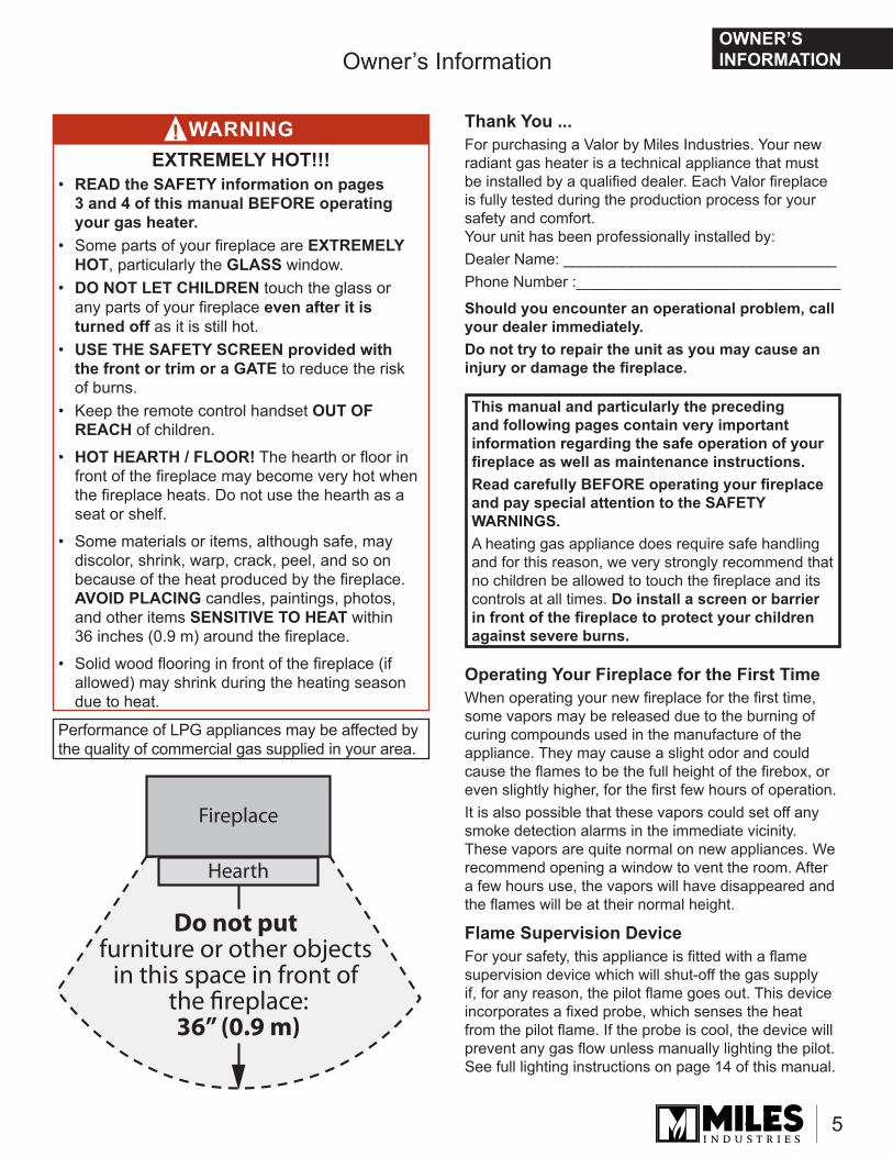
DO NOT place furniture or any other combustible household objects within 36” of the fi replace front.
READ and UNDERSTAND all instructions carefully before starting the installation. FAILURE TO FOLLOW these installation instructions may result in possible fi re hazard and will void the warranty.Prior to the fi rst fi ring of the fi replace, READ the Owner’s Information section of this manual.DO NOT USE this appliance if any part has been under water. Immediately, CALL a qualifi ed service technician to inspect the unit and to replace any part of the control system and any gas control that has been under water.THIS UNIT IS NOT FOR USE WITH SOLID FUEL.Installation and repair should be PERFORMED by a qualifi ed service person. The appliance and venting system should be INSPECTED before initial use and at least annually by a professional service person. More frequent cleaning may be required due to excessive lint from carpeting, bedding, etc. It is IMPERATIVE that the unit’s control compartment, burner, and circulating air passageways BE KEPT CLEAN to provide for adequate combustion and ventilation air.Always KEEP the appliance clear and free from combustible materials, gasoline, and other fl ammable vapors and liquids.NEVER OBSTRUCT the fl ow of combustion and ventilation air. Keep the front of the appliance CLEAR of all obstacles and materials for servicing and proper operation.
Due to the high temperature, the appliance should be LOCATED out of traffi c areas and away from furniture and draperies.Clothing or fl ammable material SHOULD NOT BE PLACED on or near the appliance.
This unit MUST be used with a vent system as described in this installation manual. NO OTHER vent system or components MAY BE USED.This gas fi replace and vent assembly MUST be vented directly to the outside and MUST NEVER be attached to a chimney serving a separate solid fuel burning appliance. Each gas appliance MUST USE a separate vent system. Common vent systems are PROHIBITED.INSPECT the external vent cap on a regular basis to make sure that no debris, plants, trees, shrubs are interfering with the air fl ow.
DO NOT OPERATE this appliance with the glass door removed, cracked, or broken. Replacement of the glass door should be performed by a licensed or qualifi ed service person. DO NOT strike or slam the glass door.The glass door assembly SHALL ONLY be replaced as a complete unit, as supplied by the fi replace manufacturer. NO SUBSTITUTE material may be used.
A BARRIER DESIGNED TO REDUCE THE RISK OF BURNS from the hot viewing glass is provided with this appliance and SHALL BE INSTALLED for the PROTECTION OF CHILDREN and other AT-RISK INDIVIDUALS.
DO NOT USE abrasive cleaners on the glass door assembly. DO NOT ATTEMPT to clean the glass door when it is hot.
If the barrier becomes damaged, the barrier SHALL BE REPLACED with the MANUFACTURER’S BARRIER for this appliance.
TURN OFF the gas before servicing this appliance. It is recommended that a qualifi ed service technician perform an appliance check-up at the beginning of each heating season.
Any safety screen, guard or barrier removed for ser-vicing the appliance, MUST BE REPLACED prior to operating the appliance.
BE CAREFUL not to put any decorating objects sensitive to heat to close above or around the fi replace as it gets very hot when operating.
DO NOT use this heater as a temporary source of heat during construction.
This appliance is a DOMESTIC ROOM-HEATING AP-PLIANCE. It must not be used for any other purposes such as drying clothes, etc.
State of California. Proposition 65 Warning. Fuels used in gas, wood-burning or oil fi red appliances, and the products of combustion of such fuels, contain chemicals known to the State of California to cause cancer, birth defects and other reproductive harm. California Health & Safety Code Sec. 25249.6.
The glass door assembly MUST be in place and sealed before the unit can be placed into safe operation.
4
Safety and Your Fireplace
Please Follow These Important Child Safety Precautions and Recommendations,• Parts of your Valor Fireplace become
extremely hot while in operation.
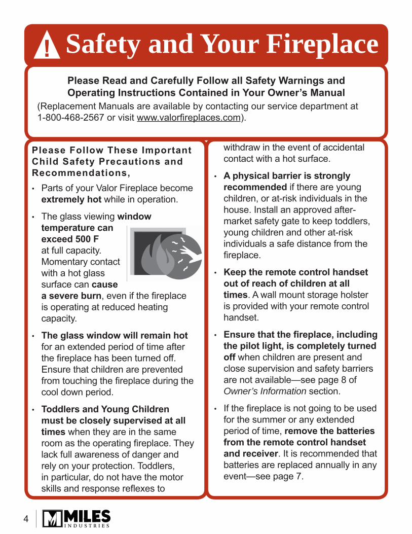
• The glass viewing window temperature can exceed 500 F at full capacity. Momentary contact with a hot glass surface can cause a severe burn, even if the fi replace is operating at reduced heating capacity.
• The glass window will remain hot for an extended period of time after the fi replace has been turned off. Ensure that children are prevented from touching the fi replace during the cool down period.
• Toddlers and Young Children must be closely supervised at all times when they are in the same room as the operating fi replace. They lack full awareness of danger and rely on your protection. Toddlers, in particular, do not have the motor skills and response refl exes to
withdraw in the event of accidental contact with a hot surface.
• A physical barrier is strongly recommended if there are young children, or at-risk individuals in the house. Install an approved after-market safety gate to keep toddlers, young children and other at-risk individuals a safe distance from the fi replace.
• Keep the remote control handset out of reach of children at all times. A wall mount storage holster is provided with your remote control handset.
• Ensure that the fi replace, including the pilot light, is completely turned off when children are present and close supervision and safety barriers are not available—see page 8 of Owner’s Information section.
• If the fi replace is not going to be used for the summer or any extended period of time, remove the batteries from the remote control handset and receiver. It is recommended that batteries are replaced annually in any event—see page 7.
Please Read and Carefully Follow all Safety Warnings and Operating Instructions Contained in Your Owner’s Manual
(Replacement Manuals are available by contacting our service department at 1-800-468-2567 or visit www.valorfi replaces.com).
Safety and Your Fireplace!
5
OWNER’S INFORMATION
Operating Your Fireplace for the First TimeWhen operating your new fi replace for the fi rst time, some vapors may be released due to the burning of curing compounds used in the manufacture of the appliance. They may cause a slight odor and could cause the fl ames to be the full height of the fi rebox, or even slightly higher, for the fi rst few hours of operation.It is also possible that these vapors could set off any smoke detection alarms in the immediate vicinity. These vapors are quite normal on new appliances. We recommend opening a window to vent the room. After a few hours use, the vapors will have disappeared and the fl ames will be at their normal height.
Flame Supervision DeviceFor your safety, this appliance is fi tted with a fl ame supervision device which will shut-off the gas supply if, for any reason, the pilot fl ame goes out. This device incorporates a fi xed probe, which senses the heat from the pilot fl ame. If the probe is cool, the device will prevent any gas fl ow unless manually lighting the pilot. See full lighting instructions on page 14 of this manual.
Owner’s Information
Performance of LPG appliances may be affected by the quality of commercial gas supplied in your area.
Do not put furniture or other objects
in this space in front of the fireplace:36” (0.9 m)
Fireplace
Hearth
WARNINGEXTREMELY HOT!!!
• READ the SAFETY information on pages 3 and 4 of this manual BEFORE operating your gas heater.
• Some parts of your fi replace are EXTREMELY HOT, particularly the GLASS window.
• DO NOT LET CHILDREN touch the glass or any parts of your fi replace even after it is turned off as it is still hot.
• USE THE SAFETY SCREEN provided with the front or trim or a GATE to reduce the risk of burns.
• Keep the remote control handset OUT OF REACH of children.
• HOT HEARTH / FLOOR! The hearth or fl oor in front of the fi replace may become very hot when the fi replace heats. Do not use the hearth as a seat or shelf.
• • Some materials or items, although safe, may Some materials or items, although safe, may discolor, shrink, warp, crack, peel, and so on discolor, shrink, warp, crack, peel, and so on because of the heat produced by the fi replace. because of the heat produced by the fi replace. AVOID PLACINGAVOID PLACING candles, paintings, photos, candles, paintings, photos, and other items and other items SENSITIVE TO HEAT SENSITIVE TO HEAT within 36 inches (0.9 m) around the fi replace.
• Solid wood fl ooring in front of the fi replace (if allowed) may shrink during the heating season due to heat.
This manual and particularly the preceding and following pages contain very important information regarding the safe operation of your fi replace as well as maintenance instructions.Read carefully BEFORE operating your fi replace and pay special attention to the SAFETY WARNINGS.A heating gas appliance does require safe handling and for this reason, we very strongly recommend that no children be allowed to touch the fi replace and its controls at all times. Do install a screen or barrier in front of the fi replace to protect your children against severe burns.
Thank You ...For purchasing a Valor by Miles Industries. Your new radiant gas heater is a technical appliance that must be installed by a qualifi ed dealer. Each Valor fi replace is fully tested during the production process for your safety and comfort.Your unit has been professionally installed by:Dealer Name: ________________________________Phone Number :_______________________________
Should you encounter an operational problem, call your dealer immediately.Do not try to repair the unit as you may cause an injury or damage the fi replace.
!
6
Cleaning Your Fireplace
Important - Glass cleaning - Mineral depositsOne of the by-products of the combustion process in a gas appliance is a mineral which can show up as a white fi lm on the ceramic glass of the viewing door.The composition of the deposit varies with location and time. It is believed to be associated with the varying sulfur content of the gas. You may have the problem intermittently.We have consulted with ceramic glass manufacturers and they cannot offer a defi nitive solution to this prob-lem. Dealers have tried various cleaning products with varying results. The following are recommendations only and are not meant to guarantee results.NOTE: This is a problem beyond Miles Industries’ control and is not covered under warranty.• Clean the glass regularly as soon as you notice
the buildup (white fi lm). If the fi lm is left for a longer period of time, it will etch into the glass. It is then much harder, if not impossible, to remove.
• NEVER use an abrasive cleaner on the ceramic glass. Any abrasion of the surface has the immediate effect of compromising the strength of the glass. An emulsion type cleaner is recommended.
• Use a soft damp cloth to apply the cleaner. Dry the glass with a soft, dry, preferably cotton cloth. Most paper towels and synthetic materials are abrasive to ceramic glass and should be avoided.
• Our dealers have had good results from the products listed below. We cannot, however, guarantee the results of these products.• Brasso, Polish Plus by Kelkem, Cook Top Clean
Creme by Elco, White Off by Rutland, Turtle WaxDo not clean the glass while it is hot!Always securely replace the window and the barrier screen before lighting.
If broken, the glass pane may only be replaced as a complete window unit as supplied by the manufacturer.If the barrier becomes damaged, the barrier shall be replaced with the manufacturer’s barrier for this appliance.
To remove the window for cleaning:1. Unhook the front and barrier
screen.2. Release the top of the
window by pulling forward and unhooking the two clamping bars at the top corners.
3. Unscrew the two spring-loaded bolts securing the bottom of the window.
4. Carefully lift the window. Keep the window and bolts in a safe place.
Clean the window following the guidelines in this section. Clean the trim or front with mild soap and water. Dust the barrier screen with a soft brush.Dust the fi rebox ceramic logs/rocks and walls with a soft brush. Dust can also be removed from the burner using a soft brush after removing the ceramic logs. When cleaning, make sure that no particles are brushed into the slots of the burner.
To refi t the window:1. Place the window centrally
against the engine unit resting it on the support at bottom front of the engine.
2. Pull the clamping bars forward and hook them to the window frame bracket to secure the top of the window.
3. Fit the two spring loaded bolts through the bottom of the window and tighten to secure the bottom of the window.
4. Pull the top of the window forward and release to ensure the springs return it in position.
5. Similarly check the bottom of the window by pulling it forward and releasing.
6. Apply light hand pressure against the window frame sides to bed in the window seal.
Owner’s Information
WARNINGDO NOT TOUCH THE GLASS WHILE IT IS HOT! Let the fi replace cool fi rst before cleaning it.
!
IMPORTANT: To ensure a safe operation, ensure that the spring-loaded mechanism functions properly.
OWNER’S INFORMATION
7
Owner’s Information
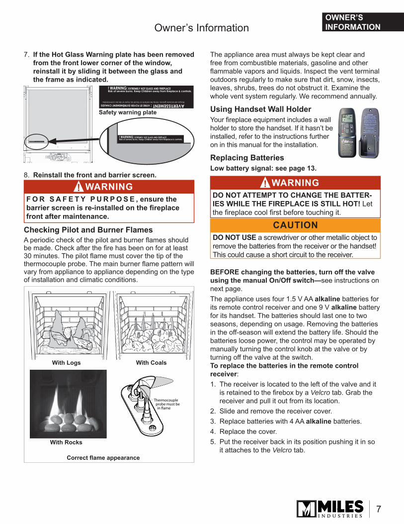
Thermocouple probe must be in flame
Correct fl ame appearance
With Logs With Coals
With Rocks
7. If the Hot Glass Warning plate has been removed from the front lower corner of the window, reinstall it by sliding it between the glass and the frame as indicated.
8. Reinstall the front and barrier screen.
Checking Pilot and Burner FlamesA periodic check of the pilot and burner fl ames should be made. Check after the fi re has been on for at least 30 minutes. The pilot fl ame must cover the tip of the thermocouple probe. The main burner fl ame pattern will vary from appliance to appliance depending on the type of installation and climatic conditions.
The appliance area must always be kept clear and free from combustible materials, gasoline and other fl ammable vapors and liquids. Inspect the vent terminal outdoors regularly to make sure that dirt, snow, insects, leaves, shrubs, trees do not obstruct it. Examine the whole vent system regularly. We recommend annually.
Using Handset Wall HolderYour fi replace equipment includes a wall holder to store the handset. If it hasn’t be installed, refer to the instructions further on in this manual for the installation.
Replacing BatteriesLow battery signal: see page 13.
BEFORE changing the batteries, turn off the valve using the manual On/Off switch —see instructions on next page.The appliance uses four 1.5 V AA alkaline batteries for its remote control receiver and one 9 V alkaline battery for its handset. The batteries should last one to two seasons, depending on usage. Removing the batteries in the off-season will extend the battery life. Should the batteries loose power, the control may be operated by manually turning the control knob at the valve or by turning off the valve at the switch.To replace the batteries in the remote control receiver: 1. The receiver is located to the left of the valve and it
is retained to the fi rebox by a Velcro tab. Grab the receiver and pull it out from its location.
2. Slide and remove the receiver cover.3. Replace batteries with 4 AA alkaline batteries.4. Replace the cover.5. Put the receiver back in its position pushing it in so
it attaches to the Velcro tab.
Safety warning plate
CAUTIONDO NOT USE a screwdriver or other metallic object to remove the batteries from the receiver or the handset! This could cause a short circuit to the receiver.
WARNINGDO NOT ATTEMPT TO CHANGE THE BATTER-IES WHILE THE FIREPLACE IS STILL HOT! Let the fi replace cool fi rst before touching it.
!WARNINGF O R S A F E T Y P U R P O S E , ensure the barrier screen is re-installed on the fi replace front after maintenance.
!
OWNER’S INFORMATION
8
ON
OFF
Wall Switch (optional)
Manual On/Off SwitchThermostatic Remote Control
Locating Lighting, Operation and Rating Information Plate
The Lighting, Operation and Rating information is located on a plate under the fi rebox.To access the plate, remove any fret or access panel and grab the plate and slide it out to read it. There is important information on both sides of the plate.
Servicing Your FireplaceIf your appliance require any attention, contact your supplier quoting the model number. It will be helpful if the appliance serial number can also be quoted. This is on the rating plate located under the fi rebox. The repair parts are shown in the separate repair parts leafl et. Please always quote part number and description when requesting spare parts.
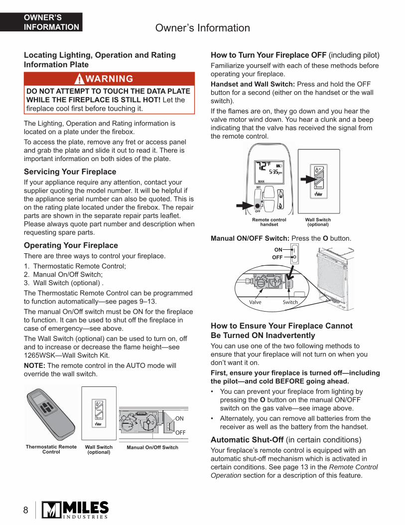
Operating Your FireplaceThere are three ways to control your fi replace.1. Thermostatic Remote Control;2. Manual On/Off Switch;3. Wall Switch (optional) .The Thermostatic Remote Control can be programmed to function automatically—see pages 9–13. The manual On/Off switch must be ON for the fi replace to function. It can be used to shut off the fi replace in case of emergency—see above.The Wall Switch (optional) can be used to turn on, off and to increase or decrease the fl ame height—see 1265WSK—Wall Switch Kit.NOTE: The remote control in the AUTO mode will override the wall switch.
Wall Switch(optional)
Remote control handset
Valve Switch
ONOFF
— OO
How to Turn Your Fireplace OFF (including pilot)Familiarize yourself with each of these methods before operating your fi replace.Handset and Wall Switch: Press and hold the OFF button for a second (either on the handset or the wall switch).If the fl ames are on, they go down and you hear the valve motor wind down. You hear a clunk and a beep indicating that the valve has received the signal from the remote control.
Manual ON/OFF Switch: Press the O button.
How to Ensure Your Fireplace Cannot Be Turned ON InadvertentlyYou can use one of the two following methods to ensure that your fi replace will not turn on when you don’t want it on. First, ensure your fi replace is turned off—including the pilot—and cold BEFORE going ahead.• You can prevent your fi replace from lighting by
pressing the O button on the manual ON/OFF switch on the gas valve—see image above.
• Alternately, you can remove all batteries from the receiver as well as the battery from the handset.
Automatic Shut-Off (in certain conditions)Your fi replace’s remote control is equipped with an automatic shut-off mechanism which is activated in certain conditions. See page 13 in the Remote Control Operation section for a description of this feature.
Owner’s Information
WARNINGDO NOT ATTEMPT TO TOUCH THE DATA PLATE WHILE THE FIREPLACE IS STILL HOT! Let the fi replace cool fi rst before touching it.
!
OWNER’S INFORMATION
9
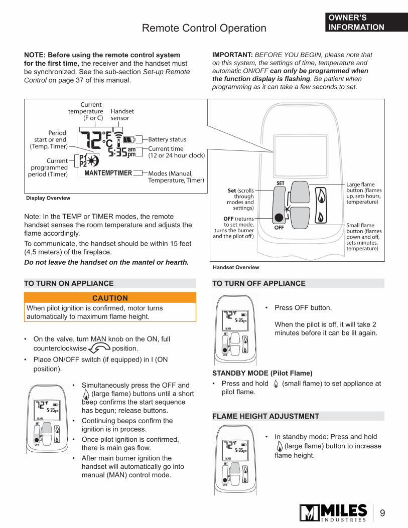
Remote Control Operation
When the pilot is off, it will take 2 minutes before it can be lit again.
TO TURN ON APPLIANCE TO TURN OFF APPLIANCE
FLAME HEIGHT ADJUSTMENT
• On the valve, turn MAN knob on the ON, full counterclockwise position.
• Place ON/OFF switch (if equipped) in I (ON position). STANDBY MODE (Pilot Flame)
• Press and hold (small fl ame) to set appliance at pilot fl ame.
• Simultaneously press the OFF and (large fl ame) buttons until a short beep confi rms the start sequence has begun; release buttons.
• Continuing beeps confi rm the ignition is in process.
• Once pilot ignition is confi rmed, there is main gas fl ow.
• After main burner ignition the handset will automatically go into manual (MAN) control mode.
• Press OFF button.
When the pilot is off, it will take 2 minutes before it can be lit again.
• In standby mode: Press and hold (large fl ame) button to increase fl ame height.
CAUTIONWhen pilot ignition is confi rmed, motor turns automatically to maximum fl ame height.
NOTE: Before using the remote control system for the fi rst time, the receiver and the handset must be synchronized. See the sub-section Set-up Remote Control on page 37 of this manual.
Set (scrollsthrough
modes andsettings)
OFF (returns to set mode,
turns the burner and the pilot off)
Large flame button (flamesup, sets hours,temperature)
Small flame button (flamesdown and off, sets minutes, temperature)
Current temperature
(F or C)
Current time (12 or 24 hour clock)
Modes (Manual, Temperature, Timer)
Handset sensor
Battery status
Current programmed
period (Timer)
Period start or end
(Temp, Timer)
Display Overview
Handset Overview
Note: In the TEMP or TIMER modes, the remote handset senses the room temperature and adjusts the fl ame accordingly. To communicate, the handset should be within 15 feet (4.5 meters) of the fi replace. Do not leave the handset on the mantel or hearth.
IMPORTANT: BEFORE YOU BEGIN, please note that on this system, the settings of time, temperature and automatic ON/OFF can only be programmed when the function display is fl ashing. Be patient when programming as it can take a few seconds to set.
OWNER’S INFORMATION
10
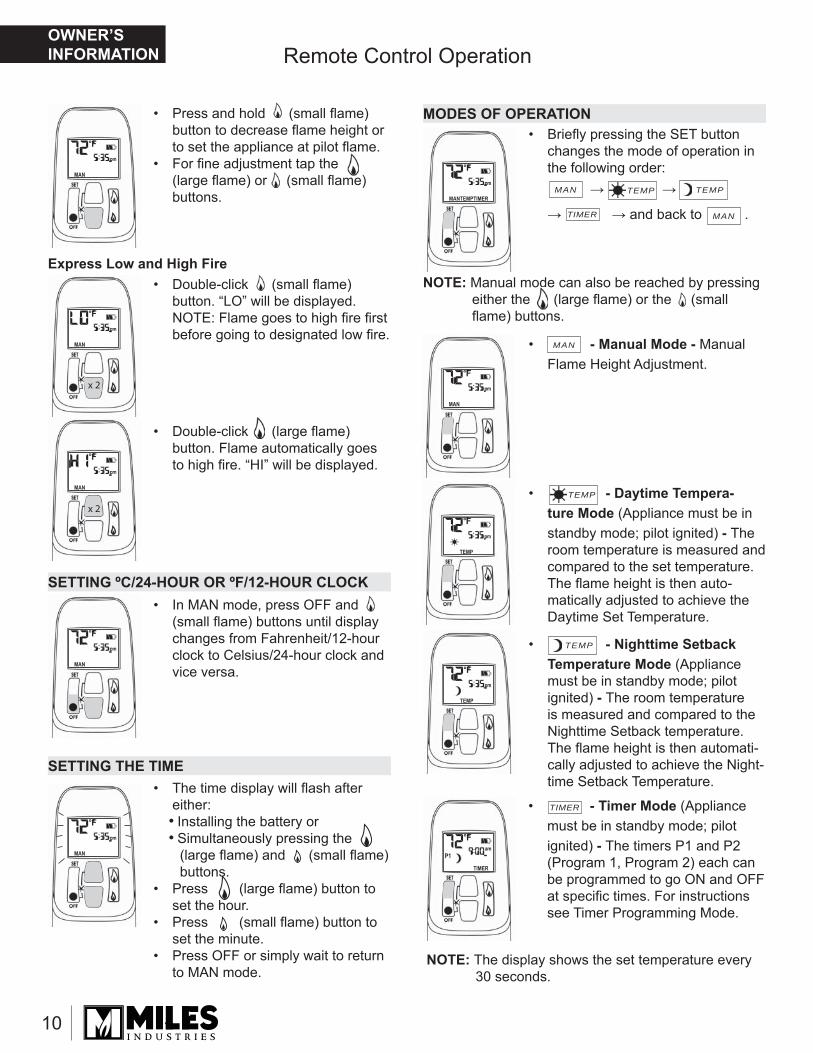
Remote Control Operation
SETTING THE TIME
SETTING ºC/24-HOUR OR ºF/12-HOUR CLOCK
MODES OF OPERATION
NOTE: Manual mode can also be reached by pressing either the (large fl ame) or the (small fl ame) buttons.
• Press and hold (small fl ame) button to decrease fl ame height or to set the appliance at pilot fl ame.
• For fi ne adjustment tap the (large fl ame) or (small fl ame) buttons.
• Briefl y pressing the SET button changes the mode of operation in the following order: → →
→ → and back to .
• Double-click (small fl ame) button. “LO” will be displayed.NOTE: Flame goes to high fi re fi rst before going to designated low fi re.
• In MAN mode, press OFF and (small fl ame) buttons until display changes from Fahrenheit/12-hour clock to Celsius/24-hour clock and vice versa.
• The time display will fl ash after either:• Installing the battery or• Simultaneously pressing the
(large fl ame) and (small fl ame) buttons.
• Press (large fl ame) button to set the hour.
• Press (small fl ame) button to set the minute.
• Press OFF or simply wait to return to MAN mode.
• Double-click (large fl ame) button. Flame automatically goes to high fi re. “HI” will be displayed.
• - Manual Mode - Manual Flame Height Adjustment.
Express Low and High Fire
• - Daytime Tempera-ture Mode (Appliance must be in standby mode; pilot ignited) - The room temperature is measured and compared to the set temperature. The fl ame height is then auto-matically adjusted to achieve the Daytime Set Temperature.
• - Nighttime Setback Temperature Mode (Appliance must be in standby mode; pilot ignited) - The room temperature is measured and compared to the Nighttime Setback temperature. The fl ame height is then automati-cally adjusted to achieve the Night-time Setback Temperature.
• - Timer Mode (Appliance must be in standby mode; pilot ignited) - The timers P1 and P2 (Program 1, Program 2) each can be programmed to go ON and OFF at specifi c times. For instructions see Timer Programming Mode.
NOTE: The display shows the set temperature every 30 seconds.
x 2
x 2
MAN
MAN
MAN
TEMPTEMP
TEMP
TIMER
TEMP
TIMER
OWNER’S INFORMATION
11
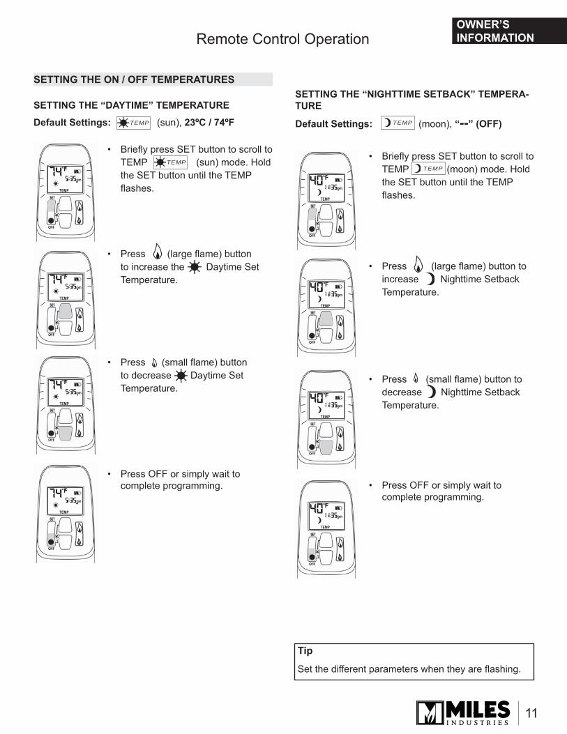
Remote Control Operation
SETTING THE ON / OFF TEMPERATURES
• Briefl y press SET button to scroll to TEMP (sun) mode. Hold the SET button until the TEMP fl ashes.
• Press (large fl ame) button to increase the Daytime Set Temperature.
• Press (small fl ame) button to decrease Daytime Set Temperature.
• Press OFF or simply wait to complete programming.
SETTING THE “DAYTIME” TEMPERATURESETTING THE “NIGHTTIME SETBACK” TEMPERA-TURE
Default Settings: (sun), 23ºC / 74ºF Default Settings: (moon), “--” (OFF)
• Press (large fl ame) button to increase Nighttime Setback Temperature.
• Press (small fl ame) button to decrease Nighttime Setback Temperature.
• Press OFF or simply wait to complete programming.
• Briefl y press SET button to scroll to TEMP (moon) mode. Hold the SET button until the TEMP fl ashes.
Tip
Set the different parameters when they are fl ashing.
TEMP
TEMP
TEMP
TEMP
OWNER’S INFORMATION
12
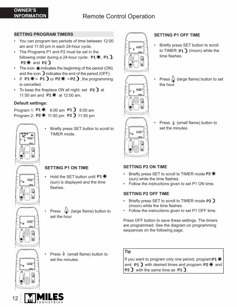
Remote Control Operation
SETTING PROGRAM TIMERS• You can program two periods of time between 12:00
am and 11:50 pm in each 24-hour cycle.• The Programs P1 and P2 must be set in the
following order during a 24-hour cycle: , , and .
• The icon indicates the beginning of the period (ON) and the icon indicates the end of the period (OFF).
• If = or = , the programming is cancelled.
• To keep the fi replace ON all night, set at 11:50 am and at 12:00 am.
Default settings:Program 1: 6:00 am 8:00 amProgram 2: 11:50 pm 11:50 pm
• Briefl y press SET button to scroll to TIMER mode.
• Hold the SET button until (sun) is displayed and the time fl ashes.
• Briefl y press SET button to scroll to TIMER (moon) while the time fl ashes.
• Press (large fl ame) button to set the hour.
• Press (large fl ame) button to set the hour.
• Press (small fl ame) button to set the minutes.
• Press (small fl ame) button to set the minutes.
SETTING P1 ON TIME SETTING P2 ON TIME• Briefl y press SET to scroll to TIMER mode
(sun) while the time fl ashes.• Follow the instructions given to set P1 ON time.
SETTING P2 OFF TIME• Briefl y press SET to scroll to TIMER mode
(moon) while the time fl ashes.• Follow the instructions given to set P1 OFF time.
Press OFF button to save these settings. The timers are programmed. See the diagram on programming sequences on the following page.
Tip
If you want to program only one period, program and with desired times and program and with the same time as .
SETTING P1 OFF TIME
P1
P1
P1
P1
P1P1
P2
P2
P2
P2
P2
P2
P1
P1
P1
P1
P1
P1
P2
P2
P2
P2
P2
OWNER’S INFORMATION
13
Options
AUTOMATIC TURN DOWN
AUTOMATIC SHUT OFF
LOW BATTERY INDICATION
HANDSET / RECEIVER MATCH
Remote handset: The battery icon will show when the battery needs to be replaced.Replace with one 9 V alkaline battery.
Receiver: Three short ‘beeps’ will sound when the motor turns when the batteries need to be replaced. Replace with four 1.5 V alkaline batteries.
The remote control handset and receiver are program-med to function together. In case of a replacement of the handset or the receiver, you will need to reset the receiver to allow them to function together. Contact your dealer for details.
• No communication. If there is no communication between the receiver and the handset for a period of 6 hours, the appliance goes into pilot mode.
• No change in fl ame height. If there is no change in fl ame height for a period of 6 hours, the appliance goes into pilot mode.NOTE: In TEMP or TIMER modes, the fl ame height will vary according to room temperature. The appli-ance will continue to work normally. However, if the room temperature remains the same for 6 hours, the appliance will go into pilot mode.
• Low batteries in the receiver. With low battery power in the receiver the system shuts off completely.NOTE: This does not apply when the power supply is interrupted.
• No change in pilot. The appliance shuts off completely when it is continually in pilot position—without any change—for a period of 5 days.
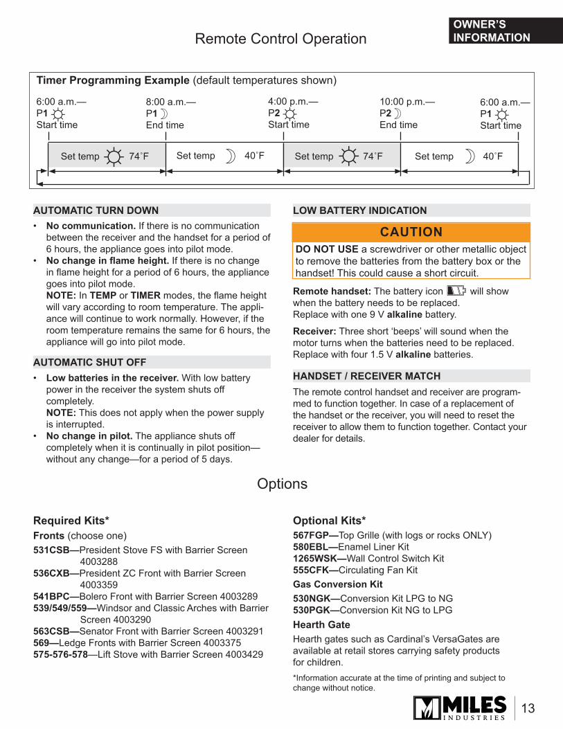
Timer Programming Example (default temperatures shown)
6:00 a.m.—P1 Start time
4:00 p.m.—P2 Start time
6:00 a.m.—P1 Start time
8:00 a.m.—P1 End time
10:00 p.m.—P2 End time
Set temp 74˚F Set temp 40˚FSet temp 74˚FSet temp 40˚F
☼ ☼ ☼
☼ ☼☽ ☽
☽ ☽
CAUTIONDO NOT USE a screwdriver or other metallic object to remove the batteries from the battery box or the handset! This could cause a short circuit.
Remote Control Operation
Required Kits*Fronts (choose one)531CSB—President Stove FS with Barrier Screen
4003288536CXB—President ZC Front with Barrier Screen
4003359541BPC—Bolero Front with Barrier Screen 4003289539/549/559—Windsor and Classic Arches with Barrier
Screen 4003290563CSB—Senator Front with Barrier Screen 4003291569—Ledge Fronts with Barrier Screen 4003375575-576-578—Lift Stove with Barrier Screen 4003429
Optional Kits*567FGP—Top Grille (with logs or rocks ONLY)580EBL—Enamel Liner Kit1265WSK—Wall Control Switch Kit555CFK—Circulating Fan KitGas Conversion Kit530NGK—Conversion Kit LPG to NG530PGK—Conversion Kit NG to LPGHearth GateHearth gates such as Cardinal’s VersaGates are available at retail stores carrying safety products for children.*Information accurate at the time of printing and subject to change without notice.
OWNER’S INFORMATION
14
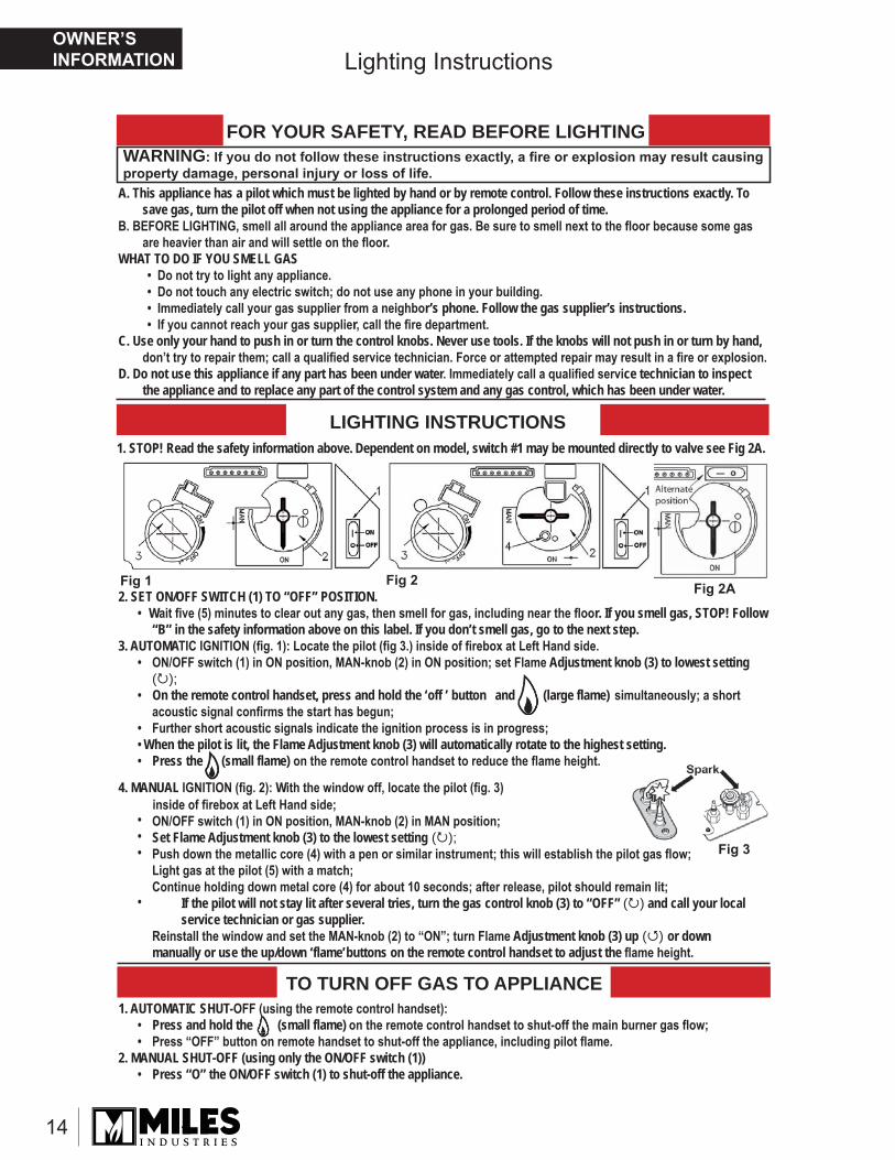
Lighting Instructions
WARNING: If you do not follow these instructions exactlyFOR YOUR SAFETY, READ BEFORE LIGHTING
A. This appliance has a pilot which must be lighted by hand or by remote control. Follow these instructions exactly. Tosave gas, turn the pilot off when not using the appliance for a prolonged period of time.
r.WHAT TO DO IF YOU SMELL GAS
r’s phone. Follow the gas supplier’s instructions.r
C. Use only your hand to push in or turn the control knobs. Never use tools. If the knobs will not push in or turn by hand,
D. Do not use this appliance if any part has been under water ce technician to inspect the appliance and to replace any part of the control system and any gas control, which has been under water.
LIGHTING INSTRUCTIONS1. STOP! Read the safety information above. Dependent on model, switch #1 may be mounted directly to valve see Fig 2A.
TO TURN OFF GAS TO APPLIANCE
2. SET ON/OFF SWITCH (1) TO “OFF” POSITION. W r. If you smell gas, STOP! Follow “B” in the safety information above on this label. If you don’t smell gas, go to the next step.
3. AUTOMAAdjustment knob (3) to lowest setting
( );On the remote control handset, press and hold the ‘off ’ button and (large flame)
When the pilot is lit, the Flame Adjustment knob (3) will automatically rotate to the highest setting.Press the (small flame)
4. MANUAL W
Set Flame Adjustment knob (3) to the lowest setting ( );
If the pilot will not stay lit after several tries, turn the gas control knob (3) to “OFF” ( ) and call your local service technician or gas supplier.
Adjustment knob (3) up ( ) or downmanually or use the up/down ‘flame’ buttons on the remote control handset to adjust the
1. AUTOMATIC SHUTPress and hold the (small flame)
2. MANUAL SHUT-OFF (using only the ON/OFF switch (1))Press “O” the ON/OFF switch (1) to shut-off the appliance.
OWNER’S INFORMATION
15
State of Massachusetts Carbon Monoxide Detector/Vent Terminal Signage RequirementsFor all side wall horizontally vented gas fueled equipment installed in every dwelling, building or structure used in whole or in part for residential purposes, including those owned or operated by the Commonwealth and where the side wall exhaust vent termination is less than seven (7) feet above fi nished grade in the area of the venting, including but not limited to decks and porches, the following requirements shall be satisfi ed:
1. INSTALLATION OF CARBON MONOXIDE DETECTORS. At the time of installation of the side wall horizontal vented gas fueled equipment, the installing plumber or gas fi tter shall observe that a hard wired carbon monoxide detector with an alarm and battery back-up is installed on the fl oor level where the gas equipment is to be installed. In addition, the installing plumber or gas fi tter shall observe that a battery operated or hard wired carbon monoxide detector with an alarm is installed on each additional level of the dwelling, building or structure served by the side wall horizontal vented gas fueled equipment. It shall be the responsibility of the property owner to secure the services of qualifi ed licensed professionals for the installation of hard wired carbon monoxide detectors.
a. In the event that the side wall horizontally vented gas fueled equipment is installed in a crawl space or an attic, the hard wired carbon monoxide detector with alarm and battery back-up may be installed on the next adjacent fl oor level.
b. In the event that the requirements of this subdivision can not be met at the time of completion of installation, the owner shall have a period of thirty (30) days to comply with the above requirements; provided, however, that during said thirty (30) day period, a battery operated carbon monoxide detector with an alarm shall be installed.
2. APPROVED CARBON MONOXIDE DETECTORS. Each carbon monoxide detector as required in accordance with the above provisions shall comply with NFPA 720 and be ANSI/UL 2034 listed and IAS certifi ed.
Commonwealth of Massachusetts
3. SIGNAGE. A metal or plastic identifi cation plate shall be permanently mounted to the exterior of the building at a minimum height of eight (8) feet above grade directly in line with the exhaust vent terminal for the horizontally vented gas fueled heating appliance or equipment. The sign shall read, in print size no less than one-half (1/2) inch in size, “GAS VENT DIRECTLY BELOW. KEEP CLEAR OF ALL OBSTRUCTIONS”.
4. INSPECTION. The state or local gas inspector of the side wall horizontally vented gas fueled equipment shall not approve the installation unless, upon inspection, the inspector observes carbon monoxide detectors and signage installed in accordance with the provisions of 248 CMR 5.08(2)(a)1 through 4.
(b) EXEMPTIONS: The following equipment is exempt from 248 CMR 5.08(2)(a)1 through 4:
1. The equipment listed in Chapter 10 entitled “Equipment Not Required To Be Vented” in the most current edition of NFPA 54 as adopted by the Board; and
2. Product Approved side wall horizontally vented gas fueled equipment installed in a room or structure separate from the dwelling, building or structure used in whole or in part for residential purposes.
(c) MANUFACTURER REQUIREMENTS - GAS EQUIPMENT VENTING SYSTEM PROVIDED. When the manufacturer of Product Approved side wall horizontally vented gas equipment provides a venting system design or venting system components with the equipment, the instructions provided by the manufacturer for installation of the equipment and the venting system shall include:
1. Detailed instructions for the installation of the venting system design or the venting system components; and
2. A complete parts list for the venting system design or venting system.
QUALIFIED INSTALLER

16
Commonwealth of Massachusetts
(d) MANUFACTURER REQUIREMENTS - GAS EQUIPMENT VENTING SYSTEM NOT PROVIDED. When the manufacturer of a Product Approved side wall horizontally vented gas fueled equipment does not provide the parts for venting the fl ue gases, but identifi es “special venting systems”, the following requirements shall be satisfi ed by the manufacturer:
1. The referenced “special venting system” instructions shall be included with the appliance or equipment installation instructions; and
2. The “special venting systems” shall be Product Approved by the Board, and the instructions for that system shall include a parts list and detailed installation instructions.
(e) A copy of all installation instructions for all Product Approved side wall horizontally vented gas fueled equipment, all venting instructions, all parts lists for venting instructions, and/or all venting design instructions shall remain with the appliance or equipment at the completion of the installation.
QUALIFIED INSTALLER
17
Specifi cations
Approvals and CodesThis appliance is certifi ed to ANSI Z21.88–2014/CSA 2.33–2014 American National Standard/CSA Standard for Vented Gas Fireplace Heaters for use in Canada and USA.The appliance complies with CSA P4.1-09, Testing method for measuring annual fi replace effi ciencies.The installation must conform with local codes or, in the absence of local codes with the National Fuel Gas Code, ANSI Z223.1or the Natural Gas and Propane Installation Code CAN/CGA-B149. Only qualifi ed licensed or trained personnel should install the appliance.The appliance, when installed, must be electrically grounded in accordance with local codes or, in the absence of local codes, with the National Electrical Code, ANSI/NFPA 70 or the Canadian Electrical Code, CSA C22.1.
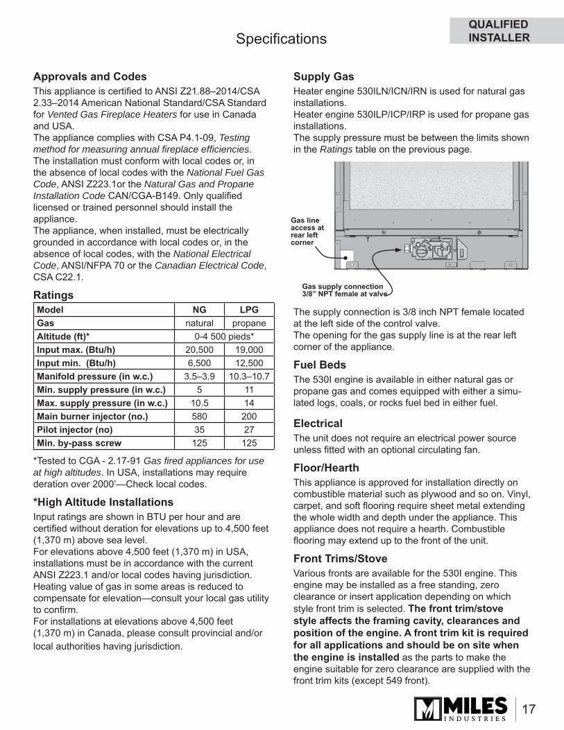
Ratings
*Tested to CGA - 2.17-91 Gas fi red appliances for use at high altitudes. In USA, installations may require deration over 2000’ —Check local codes.
*High Altitude InstallationsInput ratings are shown in BTU per hour and are certifi ed without deration for elevations up to 4,500 feet (1,370 m) above sea level.For elevations above 4,500 feet (1,370 m) in USA, installations must be in accordance with the current ANSI Z223.1 and/or local codes having jurisdiction. Heating value of gas in some areas is reduced to compensate for elevation—consult your local gas utility to confi rm.For installations at elevations above 4,500 feet (1,370 m) in Canada, please consult provincial and/or local authorities having jurisdiction.
Supply GasHeater engine 530ILN/ICN/IRN is used for natural gas installations.Heater engine 530ILP/ICP/IRP is used for propane gas installations.The supply pressure must be between the limits shown in the Ratings table on the previous page.
The supply connection is 3/8 inch NPT female located at the left side of the control valve.The opening for the gas supply line is at the rear left corner of the appliance.
Fuel BedsThe 530I engine is available in either natural gas or propane gas and comes equipped with either a simu-lated logs, coals, or rocks fuel bed in either fuel.
ElectricalThe unit does not require an electrical power source unless fi tted with an optional circulating fan.
Floor/HearthThis appliance is approved for installation directly on combustible material such as plywood and so on. Vinyl, carpet, and soft fl ooring require sheet metal extending the whole width and depth under the appliance. This appliance does not require a hearth. Combustible fl ooring may extend up to the front of the unit.
Front Trims/StoveVarious fronts are available for the 530I engine. This engine may be installed as a free standing, zero clearance or insert application depending on which style front trim is selected. The front trim/stove style affects the framing cavity, clearances and position of the engine. A front trim kit is required for all applications and should be on site when the engine is installed as the parts to make the engine suitable for zero clearance are supplied with the front trim kits (except 549 front).
Gas supply connection 3/8” NPT female at valve
Gas line access at rear left corner
Model NG LPGGas natural propaneAltitude (ft)* 0-4 500 pieds*Input max. (Btu/h) 20,500 19,000Input min. (Btu/h) 6,500 12,500Manifold pressure (in w.c.) 3.5–3.9 10.3–10.7Min. supply pressure (in w.c.) 5 11Max. supply pressure (in w.c.) 10.5 14Main burner injector (no.) 580 200Pilot injector (no) 35 27Min. by-pass screw 125 125
QUALIFIED INSTALLER
18
Dimensions, Clearance and Framing
The dimensions, clearances and framing vary with each applications and with the front trim installed. Refer to the installation instructions of the front trim chosen for more information.
Venting
WARNINGHOT HEARTH / FLOOR! The hearth or fl oor in front of the fi replace may become very hot when the fi replace heats. Do not use the hearth as a seat or shelf. Solid wood fl ooring in front of the fi replace (if allowed) may shrink during the heating season due to heat.
WARNINGSome materials or items, although safe, may discolor, shrink, warp, crack, peel, and so on because of the heat produced by the fi replace. Avoid placing candles, paintings, photos, and other items sensitive to heat around the fi replace.
! !
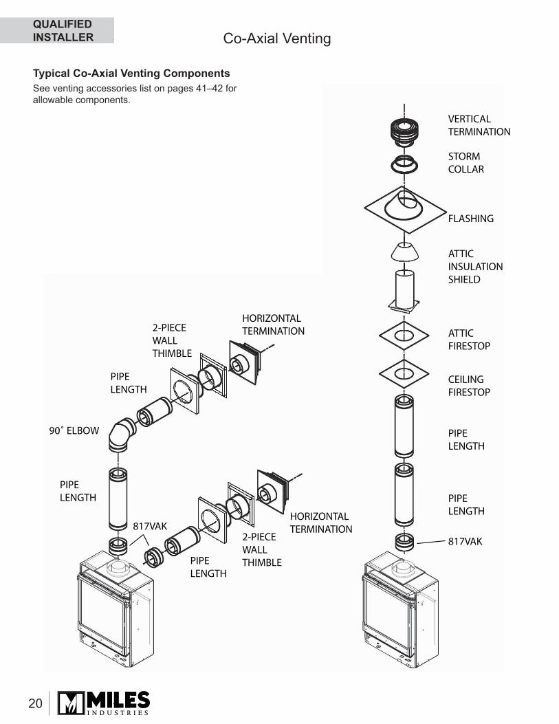
Top or Rear OutletThe 530I engine unit is supplied standard with a rear direct vent outlet and may be converted to a top direct vent outlet with no extra parts required—see Conversion to Top Outlet for Solid Direct Vent Co-axial Piping in the Appliance Preparation section further on in this manual.The 530 heater is supplied with a smooth 4-by-6-5/8-inch co-axial collar and will require an 817VAK Vent Adapter to convert the collar to a twist-lock type collar. All manufacturers’ components listed have designed their components to fi t this twist-lock type collar.Do not mix components from different manufacturers.Do not cut pipe lengths. Use adjustable lengths otherwise.
Vent MaterialThis unit is approved for installation using 4 x 6-5/8 inches approved co-axial direct vent pipes and acces-sories listed on pages 41–42 of this guide. Follow the installation instructions supplied with the individual venting accessories.This unit may also be converted to co-linear vent-ing with two 3-inch pipes for use in solid-fuel burning fi replaces and chimneys using approved adapters and accessories listed on pages 41–42 of this guide.
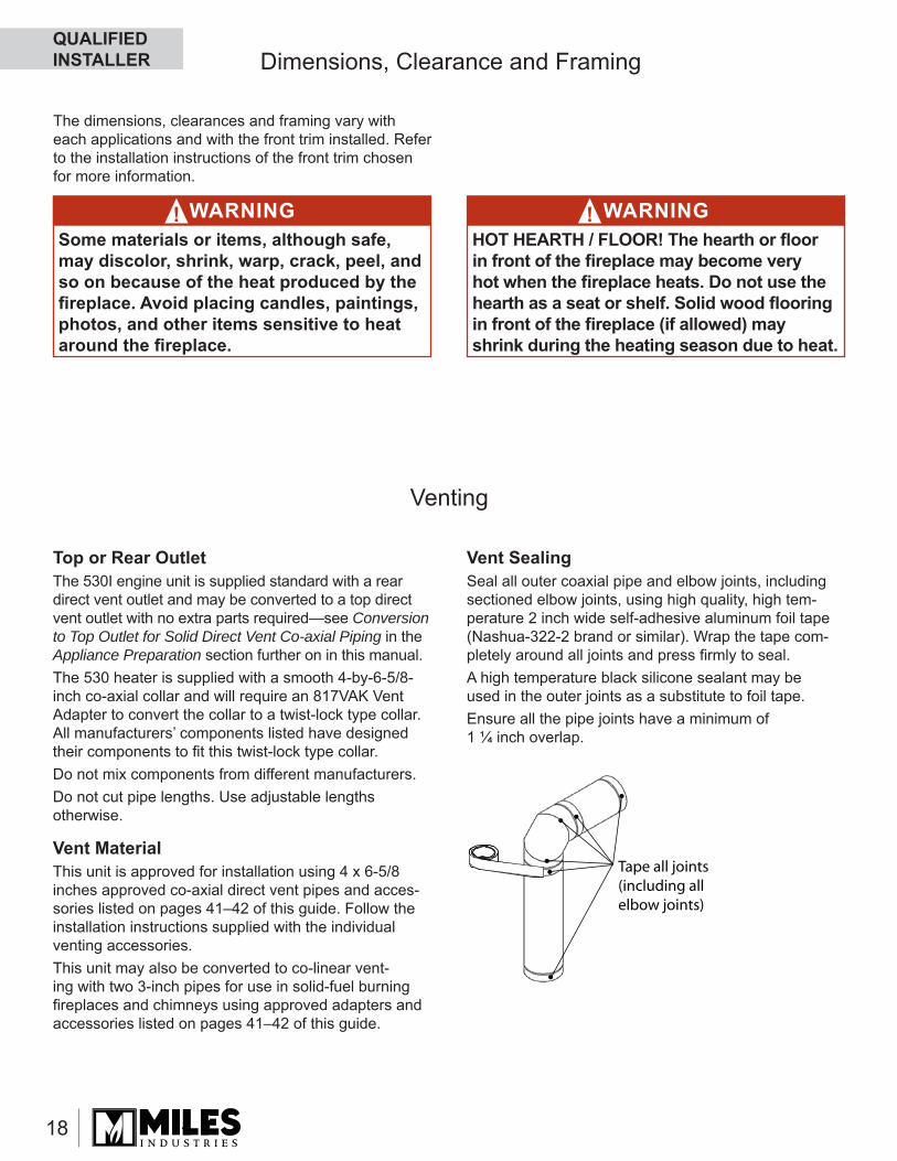
Tape all joints(including allelbow joints)
Vent SealingSeal all outer coaxial pipe and elbow joints, including sectioned elbow joints, using high quality, high tem-perature 2 inch wide self-adhesive aluminum foil tape (Nashua-322-2 brand or similar). Wrap the tape com-pletely around all joints and press fi rmly to seal. A high temperature black silicone sealant may be used in the outer joints as a substitute to foil tape.Ensure all the pipe joints have a minimum of 1 ¼ inch overlap.
QUALIFIED INSTALLER
19
Venting
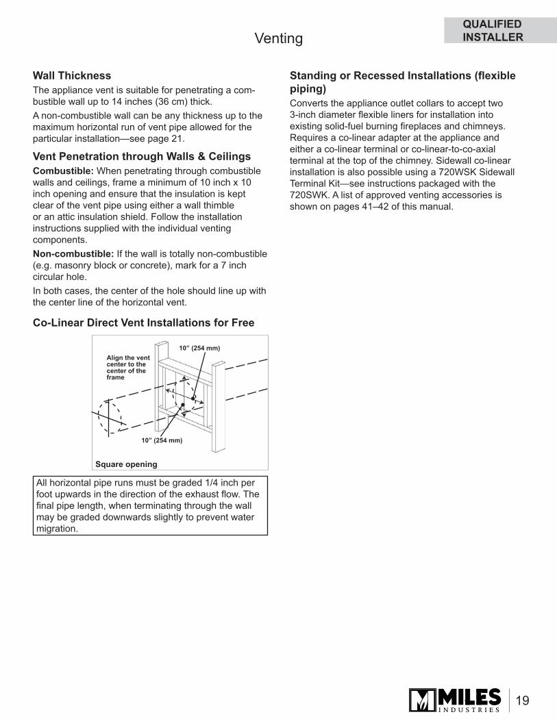
All horizontal pipe runs must be graded 1/4 inch per foot upwards in the direction of the exhaust fl ow. The fi nal pipe length, when terminating through the wall may be graded downwards slightly to prevent water migration.
10” (254 mm)
10” (254 mm)
Align the vent center to the center of the frame
Square opening
Wall ThicknessThe appliance vent is suitable for penetrating a com-bustible wall up to 14 inches (36 cm) thick.A non-combustible wall can be any thickness up to the maximum horizontal run of vent pipe allowed for the particular installation—see page 21.
Vent Penetration through Walls & CeilingsCombustible: When penetrating through combustible walls and ceilings, frame a minimum of 10 inch x 10 inch opening and ensure that the insulation is kept clear of the vent pipe using either a wall thimble or an attic insulation shield. Follow the installation instructions supplied with the individual venting components.Non-combustible: If the wall is totally non-combustible (e.g. masonry block or concrete), mark for a 7 inch circular hole. In both cases, the center of the hole should line up with the center line of the horizontal vent.
Co-Linear Direct Vent Installations for Free
Standing or Recessed Installations (fl exible piping)Converts the appliance outlet collars to accept two 3-inch diameter fl exible liners for installation into existing solid-fuel burning fi replaces and chimneys. Requires a co-linear adapter at the appliance and either a co-linear terminal or co-linear-to-co-axial terminal at the top of the chimney. Sidewall co-linear installation is also possible using a 720WSK Sidewall Terminal Kit—see instructions packaged with the 720SWK. A list of approved venting accessories is shown on pages 41–42 of this manual.
QUALIFIED INSTALLER
20
HORIZONTALTERMINATION2-PIECE
WALLTHIMBLE
HORIZONTALTERMINATION
2-PIECEWALLTHIMBLE
PIPELENGTH
PIPELENGTH
PIPELENGTH PIPE
LENGTH
817VAK
817VAK
PIPELENGTH
90˚ ELBOW
CEILINGFIRESTOP
ATTICFIRESTOP
ATTICINSULATIONSHIELD
FLASHING
STORMCOLLAR
VERTICALTERMINATION
Typical Co-Axial Venting Components
Co-Axial Venting
See venting accessories list on pages 41–42 for allowable components.
QUALIFIED INSTALLER
21
Important Installer Notice – Weather Sealing & Vapor BarriersIt is the installer’s responsibility to ensure that vent installations through exterior walls are caulked and weatherproofed in such a manner as to:
• Prevent rain water from entering the wall from the weather side by adequately caulking the outer vent plate to the exterior wall surface.
• Prevent moisture inside the home from penetrating into the wall structure by ensuring the inside wall plate is adequately sealed to the inside vapor barrier.
• Prevent rain water and moisture from entering the walls by sealing the joints between the outer vent tube and the inner and outer wall plates.
We recommend the use of a high quality polyurethane sealant.
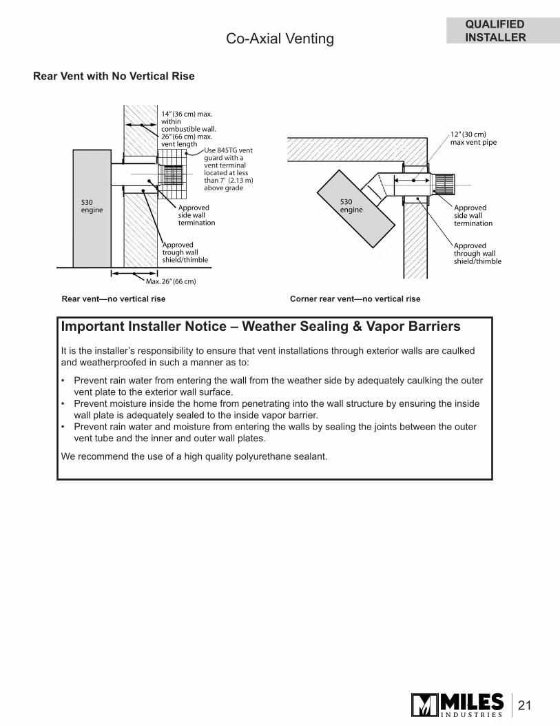
Co-Axial Venting
Rear Vent with No Vertical Rise
Approvedtrough wallshield/thimble
Approvedside walltermination
530engine
Max. 26” (66 cm)
14” (36 cm) max.withincombustible wall.26” (66 cm) max.vent length
Use 845TG vent guard with a vent terminallocated at less than 7’ (2.13 m) above grade
Rear vent—no vertical rise Corner rear vent—no vertical rise
Approvedthrough wallshield/thimble
Approvedside walltermination
530engine
12” (30 cm)max vent pipe
QUALIFIED INSTALLER
22
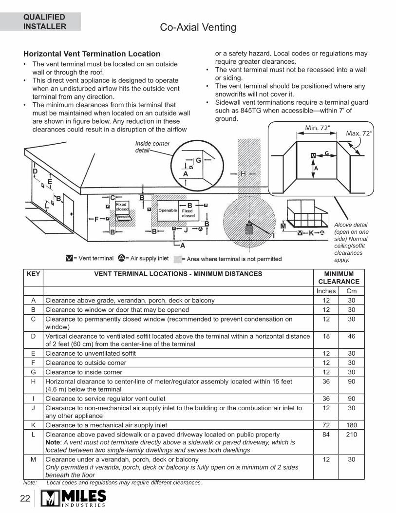
Horizontal Vent Termination Location• The vent terminal must be located on an outside
wall or through the roof.• This direct vent appliance is designed to operate
when an undisturbed airfl ow hits the outside vent terminal from any direction.
• The minimum clearances from this terminal that must be maintained when located on an outside wall are shown in fi gure below. Any reduction in these clearances could result in a disruption of the airfl ow
KEY VENT TERMINAL LOCATIONS - MINIMUM DISTANCES MINIMUM CLEARANCE
Inches CmA Clearance above grade, verandah, porch, deck or balcony 12 30B Clearance to window or door that may be opened 12 30C Clearance to permanently closed window (recommended to prevent condensation on
window) 12 30
D Vertical clearance to ventilated soffi t located above the terminal within a horizontal distance of 2 feet (60 cm) from the center-line of the terminal
18 46
E Clearance to unventilated soffi t 12 30F Clearance to outside corner 12 30G Clearance to inside corner 12 30H Horizontal clearance to center-line of meter/regulator assembly located within 15 feet
(4.6 m) below the terminal36 90
I Clearance to service regulator vent outlet 36 90J Clearance to non-mechanical air supply inlet to the building or the combustion air inlet to
any other appliance12 30
K Clearance to a mechanical air supply inlet 72 180L Clearance above paved sidewalk or a paved driveway located on public property
Note: A vent must not terminate directly above a sidewalk or paved driveway, which is located between two single-family dwellings and serves both dwellings
84 210
M Clearance under a verandah, porch, deck or balconyOnly permitted if veranda, porch, deck or balcony is fully open on a minimum of 2 sides beneath the fl oor
12 30
Note: Local codes and regulations may require different clearances.
V G
A
Min. 72”Max. 72”
Alcove detail (open on one side) Normal ceiling/soffi t clearances apply.
or a safety hazard. Local codes or regulations may require greater clearances.
• The vent terminal must not be recessed into a wall or siding.
• The vent terminal should be positioned where any snowdrifts will not cover it.
• Sidewall vent terminations require a terminal guard such as 845TG when accessible—within 7’ of ground.
Co-Axial VentingQUALIFIED INSTALLER
23
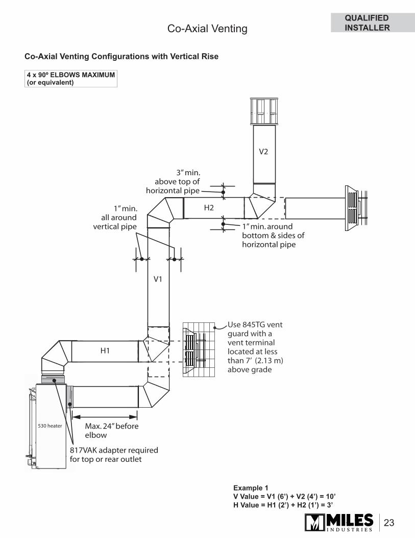
Use 845TG vent guard with a vent terminallocated at less than 7’ (2.13 m) above grade
V1
V2
H1
H21” min.all around
vertical pipe
3” min.above top of
horizontal pipe
1” min. aroundbottom & sides ofhorizontal pipe
817VAK adapter required for top or rear outlet
530 heater Max. 24” beforeelbow
4 x 90º ELBOWS MAXIMUM (or equivalent)
Co-Axial Venting Confi gurations with Vertical Rise
Example 1V Value = V1 (6’) + V2 (4’) = 10’H Value = H1 (2’) + H2 (1’) = 3’
Co-Axial VentingQUALIFIED INSTALLER
24
40
38
36
34
32
30
28
26
24
22
20
18
16
14
12
10
8
6
4
2
2 4 6 8 10 12 14 16
Top or Rear outlet
1
1
3 5
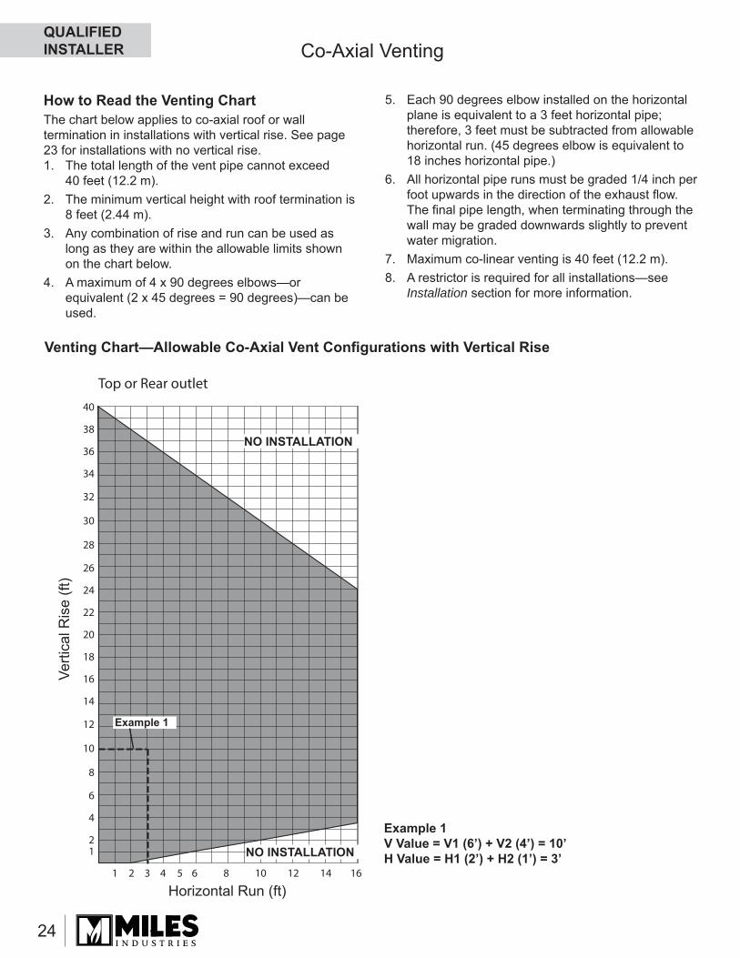
How to Read the Venting ChartThe chart below applies to co-axial roof or wall termination in installations with vertical rise. See page 23 for installations with no vertical rise.1. The total length of the vent pipe cannot exceed
40 feet (12.2 m).2. The minimum vertical height with roof termination is
8 feet (2.44 m).3. Any combination of rise and run can be used as
long as they are within the allowable limits shown on the chart below.
4. A maximum of 4 x 90 degrees elbows—or equivalent (2 x 45 degrees = 90 degrees)—can be used.
5. Each 90 degrees elbow installed on the horizontal plane is equivalent to a 3 feet horizontal pipe; therefore, 3 feet must be subtracted from allowable horizontal run. (45 degrees elbow is equivalent to 18 inches horizontal pipe.)
6. All horizontal pipe runs must be graded 1/4 inch per foot upwards in the direction of the exhaust fl ow. The fi nal pipe length, when terminating through the wall may be graded downwards slightly to prevent water migration.
7. Maximum co-linear venting is 40 feet (12.2 m).8. A restrictor is required for all installations—see
Installation section for more information.
Verti
cal R
ise
(ft)
Horizontal Run (ft)
NO INSTALLATION
NO INSTALLATION
Example 1
Co-Axial Venting
Venting Chart—Allowable Co-Axial Vent Confi gurations with Vertical Rise
Example 1V Value = V1 (6’) + V2 (4’) = 10’H Value = H1 (2’) + H2 (1’) = 3’
QUALIFIED INSTALLER
25
Co-Axial Venting
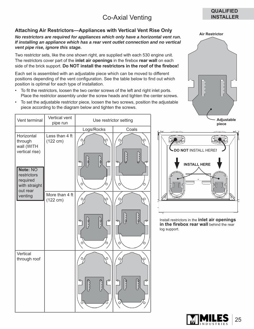
Attaching Air Restrictors—Appliances with Vertical Vent Rise OnlyNo restrictors are required for appliances which only have a horizontal vent run. If installing an appliance which has a rear vent outlet connection and no vertical vent pipe rise, ignore this stage.Two restrictor sets, like the one shown right, are supplied with each 530 engine unit. The restrictors cover part of the inlet air openings in the fi rebox rear wall on each side of the brick support. Do NOT install the restrictors in the roof of the fi rebox!Each set is assembled with an adjustable piece which can be moved to different positions depending of the vent confi guration. See the table below to fi nd out which position is optimal for each type of installation.• To fi t the restrictors, loosen the two center screws of the left and right inlet ports.
Place the restrictor assembly under the screw heads and tighten the center screws.• To set the adjustable restrictor piece, loosen the two screws, position the adjustable
piece according to the diagram below and tighten the screws.
Adjustable piece
DO NOT INSTALL HERE!
INSTALL HERE
Air Restrictor
Install restrictors in the inlet air openings in the fi rebox rear wall behind the rear log support.
Vent terminal Vertical vent pipe run Use restrictor setting
Logs/Rocks CoalsHorizontal through wall (WITH vertical rise)
Less than 4 ft (122 cm)
More than 4 ft (122 cm)
Vertical through roof
Note: NO restrictors required with straight out rear venting
QUALIFIED INSTALLER
26
‘H’
Horizontaloverhang
Verticalwall
Terminationcap
Stormcollar
Roofflashing
Plumber’s tapefixed to wall strap
Wall strap
Ceilingfirestop
Ceilingsupport
Offset elbows
Min.18”
Overhang should not extend beyondvent if within 48” of termination cap
Min. 24”(unvented soffit)Min. 36”(vented soffit)
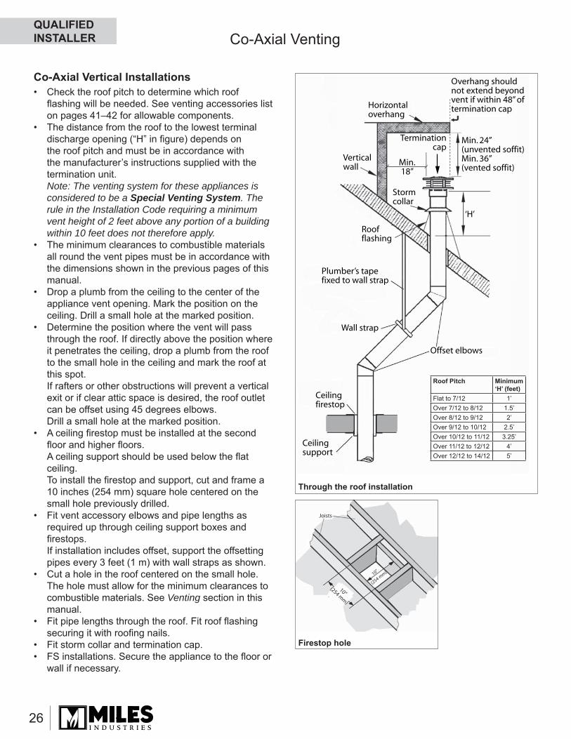
Roof Pitch Minimum ‘H’ (feet)
Flat to 7/12 1’Over 7/12 to 8/12 1.5’Over 8/12 to 9/12 2’Over 9/12 to 10/12 2.5’Over 10/12 to 11/12 3.25’Over 11/12 to 12/12 4’Over 12/12 to 14/12 5’
Joists
10”
(254 mm)
10”(254 m
m)
Co-Axial Venting
Co-Axial Vertical Installations• Check the roof pitch to determine which roof fl ashing will be needed. See venting accessories list on pages 41–42 for allowable components.
• The distance from the roof to the lowest terminal discharge opening (“H” in fi gure) depends on the roof pitch and must be in accordance with the manufacturer’s instructions supplied with the termination unit.Note: The venting system for these appliances is considered to be a Special Venting System. The rule in the Installation Code requiring a minimum vent height of 2 feet above any portion of a building within 10 feet does not therefore apply.
• The minimum clearances to combustible materials all round the vent pipes must be in accordance with the dimensions shown in the previous pages of this manual.
• Drop a plumb from the ceiling to the center of the appliance vent opening. Mark the position on the ceiling. Drill a small hole at the marked position.
• Determine the position where the vent will pass through the roof. If directly above the position where it penetrates the ceiling, drop a plumb from the roof to the small hole in the ceiling and mark the roof at this spot.If rafters or other obstructions will prevent a vertical exit or if clear attic space is desired, the roof outlet can be offset using 45 degrees elbows.Drill a small hole at the marked position.
• A ceiling fi restop must be installed at the second fl oor and higher fl oors.A ceiling support should be used below the fl at ceiling.To install the fi restop and support, cut and frame a 10 inches (254 mm) square hole centered on the small hole previously drilled.
• Fit vent accessory elbows and pipe lengths as required up through ceiling support boxes and fi restops.If installation includes offset, support the offsetting pipes every 3 feet (1 m) with wall straps as shown.
• Cut a hole in the roof centered on the small hole. The hole must allow for the minimum clearances to combustible materials. See Venting section in this manual.
• Fit pipe lengths through the roof. Fit roof fl ashing securing it with roofi ng nails.
• Fit storm collar and termination cap.• FS installations. Secure the appliance to the fl oor or
wall if necessary.
Through the roof installation
Firestop hole
QUALIFIED INSTALLER
27
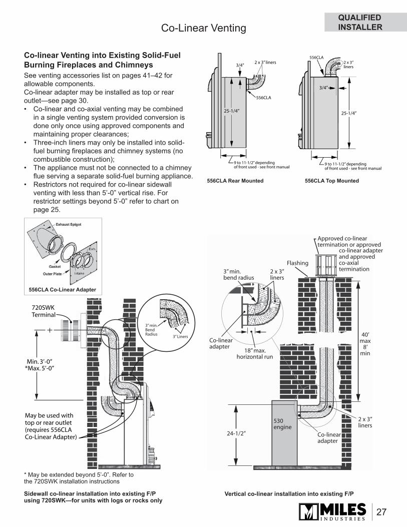
Co-Linear Venting
Co-linear Venting into Existing Solid-Fuel Burning Fireplaces and ChimneysSee venting accessories list on pages 41–42 for allowable components. Co-linear adapter may be installed as top or rear outlet—see page 30.• Co-linear and co-axial venting may be combined
in a single venting system provided conversion is done only once using approved components and maintaining proper clearances;
• Three-inch liners may only be installed into solid-fuel burning fi replaces and chimney systems (no combustible construction);
• The appliance must not be connected to a chimney fl ue serving a separate solid-fuel burning appliance.
• Restrictors not required for co-linear sidewall venting with less than 5’-0” vertical rise. For restrictor settings beyond 5’-0” refer to chart on page 25.
Flashing
2 x 3”liners
24-1/2”
3” min.bend radius
Co-linearadapter
2 x 3”liners
18” max.horizontal run
Co-linearadapter
530engine
40’max
8’min
Approved co-linear termination or approved
co-linear adapterand approvedco-axialtermination
2 x 3” liners3/4”
25-1/4”
556CLA
9 to 11-1/2” dependingof front used - see front manual
25-1/4”
3/4”
556CLA2 x 3”liners
9 to 11-1/2” dependingof front used - see front manual
Vertical co-linear installation into existing F/PSidewall co-linear installation into existing F/P using 720SWK—for units with logs or rocks only
556CLA Rear Mounted 556CLA Top Mounted
556CLA Co-Linear Adapter
Min. 3’-0”*Max. 5’-0”
May be used withtop or rear outlet(requires 556CLACo-Linear Adapter)
720SWK Terminal
3” Liners
3” min. BendRadius
* May be extended beyond 5’-0”. Refer to the 720SWK installation instructions
QUALIFIED INSTALLER
28
Co-Linear Venting
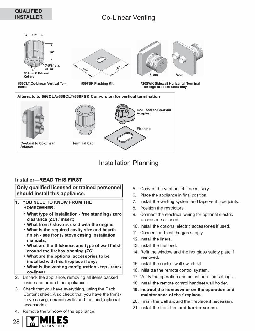
Alternate to 556CLA/559CLT/559FSK Conversion for vertical termination
Co-Axial to Co-Linear Adapter
10”
10”
3” Inlet & ExhaustCollars
7-5/8” dia.collar
559FSK Flashing Kit559CLT Co-Linear Vertical Ter-minal
Terminal Cap
Co-Linear to Co-Axial Adapter
Flashing
720SWK Sidewall Horizontal Terminal—for logs or rocks units only
Front Rear
Only qualifi ed licensed or trained personnel should install this appliance.
Installer—READ THIS FIRST
1. YOU NEED TO KNOW FROM THE HOMEOWNER:• What type of installation - free standing / zero
clearance (ZC) / insert;• What front / stove is used with the engine;• What is the required cavity size and hearth fi nish - see front / stove casing installation manuals;
• What are the thickness and type of wall fi nish around the fi rebox opening (ZC)
• What are the optional accessories to be installed with this fi replace if any;
• What is the venting confi guration - top / rear / co-linear
2. Unpack the appliance, removing all items packed inside and around the appliance.
3. Check that you have everything, using the Pack Content sheet. Also check that you have the front / stove casing, ceramic walls and fuel bed, optional accessories.
4. Remove the window of the appliance.
5. Convert the vent outlet if necessary.6. Place the appliance in fi nal position.7. Install the venting system and tape vent pipe joints.8. Position the restrictors.9. Connect the electrical wiring for optional electric
accessories if used.10. Install the optional electric accessories if used.11. Connect and test the gas supply.12. Install the liners.13. Install the fuel bed.14. Refi t the window and the hot glass safety plate if
removed.15. Install the control wall switch kit.16. Initialize the remote control system.17. Verify the operation and adjust aeration settings.18. Install the remote control handset wall holder.19. Instruct the homeowner on the operation and
maintenance of the fi replace.20. Finish the wall around the fi replace if necessary.21. Install the front trim and barrier screen.
Installation Planning
QUALIFIED INSTALLER
29
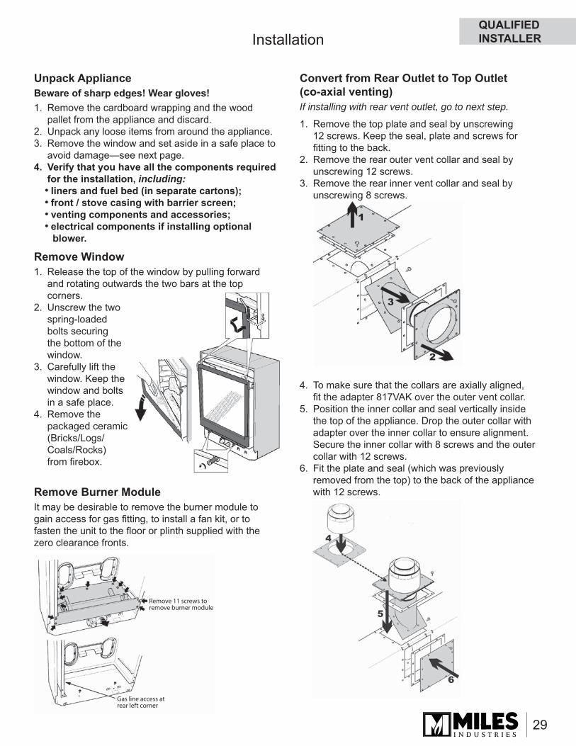
Convert from Rear Outlet to Top Outlet (co-axial venting)If installing with rear vent outlet, go to next step.
1. Remove the top plate and seal by unscrewing 12 screws. Keep the seal, plate and screws for fi tting to the back.
2. Remove the rear outer vent collar and seal by unscrewing 12 screws.
3. Remove the rear inner vent collar and seal by unscrewing 8 screws.
4. To make sure that the collars are axially aligned, fi t the adapter 817VAK over the outer vent collar.
5. Position the inner collar and seal vertically inside the top of the appliance. Drop the outer collar with adapter over the inner collar to ensure alignment. Secure the inner collar with 8 screws and the outer collar with 12 screws.
6. Fit the plate and seal (which was previously removed from the top) to the back of the appliance with 12 screws.
Installation
Unpack ApplianceBeware of sharp edges! Wear gloves!1. Remove the cardboard wrapping and the wood
pallet from the appliance and discard.2. Unpack any loose items from around the appliance.3. Remove the window and set aside in a safe place to
avoid damage—see next page.4. Verify that you have all the components required
for the installation, including:• liners and fuel bed (in separate cartons);• front / stove casing with barrier screen;• venting components and accessories;• electrical components if installing optional
blower.
Remove Window1. Release the top of the window by pulling forward
and rotating outwards the two bars at the top corners.
2. Unscrew the two spring-loaded bolts securing the bottom of the window.
3. Carefully lift the window. Keep the window and bolts in a safe place.
4. Remove the packaged ceramic (Bricks/Logs/Coals/Rocks) from fi rebox.
Remove Burner ModuleIt may be desirable to remove the burner module to gain access for gas fi tting, to install a fan kit, or to fasten the unit to the fl oor or plinth supplied with the zero clearance fronts.
Remove 11 screws to remove burner module
Gas line access atrear left corner
QUALIFIED INSTALLER
30
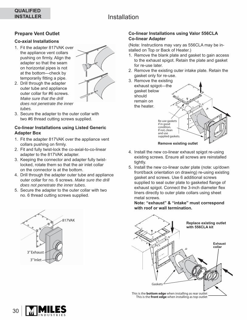
Prepare Vent OutletCo-axial Installations1. Fit the adapter 817VAK over
the appliance vent collars pushing on fi rmly. Align the adapter so that the seam on horizontal pipes is not at the bottom—check by temporarily fi tting a pipe.
2. Drill through the adapter outer tube and appliance outer collar for #6 screws. Make sure that the drill does not penetrate the inner tubes.
3. Secure the adapter to the outer collar with two #6 thread cutting screws supplied.
Co-linear Installations using Listed Generic Adapter Box1. Fit the adapter 817VAK over the appliance vent
collars pushing on fi rmly.2. Fit and fully twist-lock the co-axial-to-co-linear
adapter to the 817VAK adapter.3. Keeping the connector and adapter fully twist-
locked, rotate them so that the air inlet collar on the connector is at the bottom.
4. Drill through the adapter outer tube and appliance outer collar for no. 6 screws. Make sure the drill does not penetrate the inner tubes.
5. Secure the adapter to the outer collar with two no. 6 thread cutting screws supplied.
Co-linear Installations using Valor 556CLA Co-linear Adapter(Note: Instructions may vary as 556CLA may be in-stalled on Top or Back of Heater.)1. Remove the blank plate and gasket to gain access
to the exhaust spigot. Retain the plate and gasket for re-use later.
2. Remove the existing outer intake plate. Retain the gasket only for re-use.
3. Remove the existing exhaust spigot—the gasket below should remain on the heater.
4. Install the new co-linear exhaust spigot re-using existing screws. Ensure all screws are reinstalled tightly.
5. Install the new co-linear outer plate (note: up/down front/back orientation on drawing) re-using existing gasket and screws. Use 6 additional screws supplied to seal outer plate to gasketed fl ange of exhaust spigot. Connect the 3-inch diameter fl ex liners directly to outer plate collars using sheet metal screws.Note: “exhaust” & “intake” must correspond with roof or wall termination.
Gaskets
This is the bottom edge when installing as rear outletThis is the front edge when installing as top outlet
Installation
Re-use gaskets if in good condition. If not, clean and use supplied gaskets.
Remove existing outlet
Replace existing outlet with 556CLA kit
817VAK
3” Exhaust
3” Inlet
Exhaust collar
QUALIFIED INSTALLER
31
Installation
Connect Gas Supply• It’s preferable to rough-in the gas line at this point
before proceeding with the fi rebox installation.• The appliance is supplied for supply gas connection
at the control valve. Supply line connection to the control valve of the appliance is 3/8 inch NPT (female).Take care not to apply torque to the valve. An isolating valve may be fi tted within the appliance case. Be aware that the supply pipe should follow routing to clear the remote receiver or optional fan.
• Use only new black iron or steel pipes or copper tubing if acceptable—check local codes. Note that in USA, copper tubing must be internally tinned for protection against sulfur compounds.
• Unions in gas lines should be of ground joint type.• The gas supply line must be sized and installed
to provide a supply of gas suffi cient to meet the maximum demand of the appliance without undue loss of pressure.
• Sealant used must be resistant to the action of all gas constituents including LP gas. Sealant should be applied lightly to male threads to ensure excess sealant does not enter gas lines.
• The supply line should include a manual shut-off valve and union to allow the appliance to be disconnected for servicing.
• Pressure test the supply line for leaks.• The appliance and its individual shut-off valve
must be disconnected from the gas supply piping system during any pressure testing of that system at test pressures in excess of 1/2 psig (3.5kPa).
• The appliance must be isolated from the gas supply piping system by closing its individual manual shut-off valve during any pressure testing of the gas supply piping system at test pressures equal to or less than 1/2 psig (3.5kPa).
• Failure to either disconnect or isolate the appliance during pressure testing may result in regulator or valve damage. Consult your dealer in this case.
• The minimum supply pressure is given in Specifi cations section of this manual.
• All piping and connections must be tested for leaks after installation or servicing. All leaks must be corrected immediately.
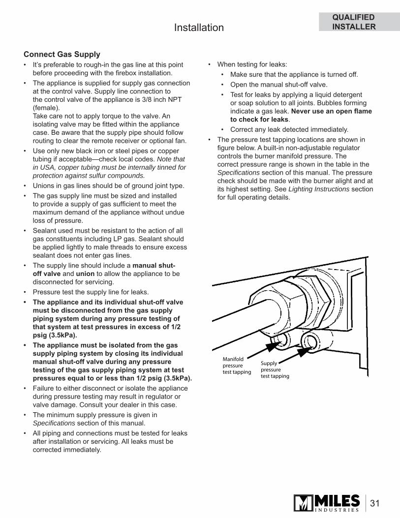
Supply pressuretest tapping
Manifold pressuretest tapping
• When testing for leaks:• Make sure that the appliance is turned off.• Open the manual shut-off valve.• Test for leaks by applying a liquid detergent
or soap solution to all joints. Bubbles forming indicate a gas leak. Never use an open fl ame to check for leaks.
• Correct any leak detected immediately.• The pressure test tapping locations are shown in fi gure below. A built-in non-adjustable regulator controls the burner manifold pressure. The correct pressure range is shown in the table in the Specifi cations section of this manual. The pressure check should be made with the burner alight and at its highest setting. See Lighting Instructions section for full operating details.
QUALIFIED INSTALLER
32
Installation
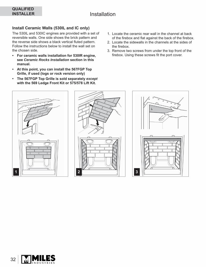
Install Ceramic Walls (530IL and IC only)The 530IL and 530IC engines are provided with a set of reversible walls. One side shows the brick pattern and the reverse side shows a black vertical fl uted pattern. Follow the instructions below to install the wall set on the chosen side. • For ceramic walls installation for 530IR engine,
see Ceramic Rocks Installation section in this manual.
• At this point, you can install the 567FGP Top Grille, if used (logs or rock version only)
• The 567FGP Top Grille is sold separately except with the 569 Ledge Front Kit or 575/578 Lift Kit.
1 32
1. Locate the ceramic rear wall in the channel at back of the fi rebox and fl at against the back of the fi rebox.
2. Locate the sidewalls in the channels at the sides of the fi rebox.
3. Remove two screws from under the top front of the fi rebox. Using these screws fi t the port cover.
QUALIFIED INSTALLER
33
Installation
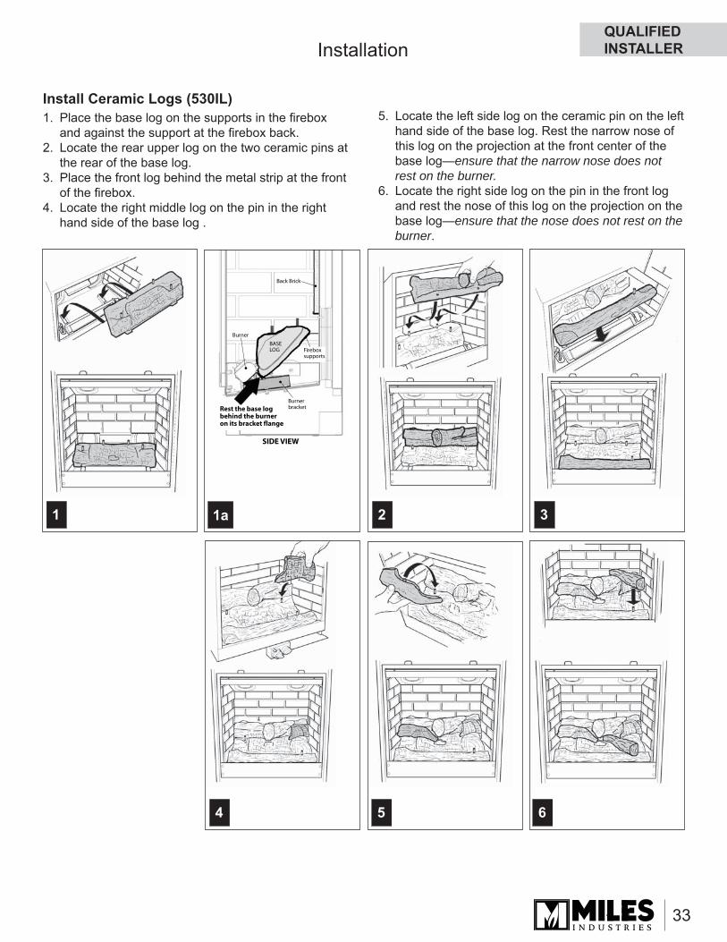
Install Ceramic Logs (530IL)1. Place the base log on the supports in the fi rebox
and against the support at the fi rebox back.2. Locate the rear upper log on the two ceramic pins at
the rear of the base log.3. Place the front log behind the metal strip at the front
of the fi rebox.4. Locate the right middle log on the pin in the right
hand side of the base log .
64 5
1 2 3
Burner
SIDE VIEW
Back Brick
Burner bracketRest the base log
behind the burner on its bracket flange
BASE LOG Firebox
supports
1a
5. Locate the left side log on the ceramic pin on the left hand side of the base log. Rest the narrow nose of this log on the projection at the front center of the base log—ensure that the narrow nose does not rest on the burner.
6. Locate the right side log on the pin in the front log and rest the nose of this log on the projection on the base log —ensure that the nose does not rest on the burner.
QUALIFIED INSTALLER
34
Installation
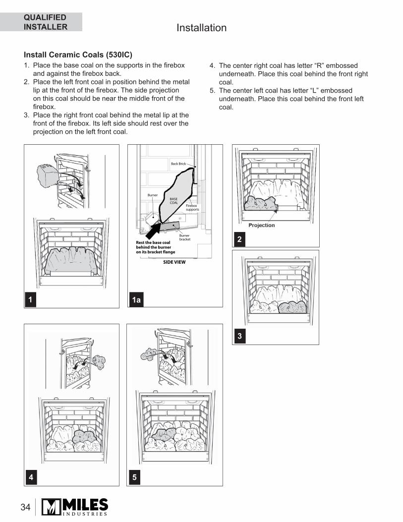
Install Ceramic Coals (530IC)1. Place the base coal on the supports in the fi rebox
and against the fi rebox back.2. Place the left front coal in position behind the metal
lip at the front of the fi rebox. The side projection on this coal should be near the middle front of the fi rebox.
3. Place the right front coal behind the metal lip at the front of the fi rebox. Its left side should rest over the projection on the left front coal.
1
2
4 5
3
1a
Burner
SIDE VIEW
Back Brick
Burner bracket
Rest the base coal behind the burner on its bracket flange
BASE COAL
Firebox supports
4. The center right coal has letter “R” embossed underneath. Place this coal behind the front right coal.
5. The center left coal has letter “L” embossed underneath. Place this coal behind the front left coal.
QUALIFIED INSTALLER
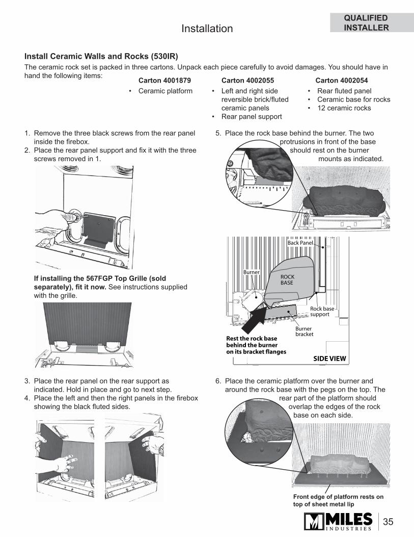
35
Installation
Install Ceramic Walls and Rocks (530IR)The ceramic rock set is packed in three cartons. Unpack each piece carefully to avoid damages. You should have in hand the following items: Carton 4001879
• Ceramic platformCarton 4002055
• Left and right side reversible brick/fl uted ceramic panels
• Rear panel support
Carton 4002054• Rear fl uted panel• Ceramic base for rocks• 12 ceramic rocks
1. Remove the three black screws from the rear panel inside the fi rebox.
2. Place the rear panel support and fi x it with the three screws removed in 1.
If installing the 567FGP Top Grille (sold separately), fi t it now. See instructions supplied with the grille.
3. Place the rear panel on the rear support as indicated. Hold in place and go to next step.
4. Place the left and then the right panels in the fi rebox showing the black fl uted sides.
5. Place the rock base behind the burner. The two protrusions in front of the base
should rest on the burner mounts as indicated.
6. Place the ceramic platform over the burner and around the rock base with the pegs on the top. The
rear part of the platform should overlap the edges of the rock
base on each side.
Burner
SIDE VIEW
Back Panel
Burner bracket
Rest the rock base behind the burner on its bracket flanges
ROCKBASE
Rock basesupport
Front edge of platform rests on top of sheet metal lip
QUALIFIED INSTALLER
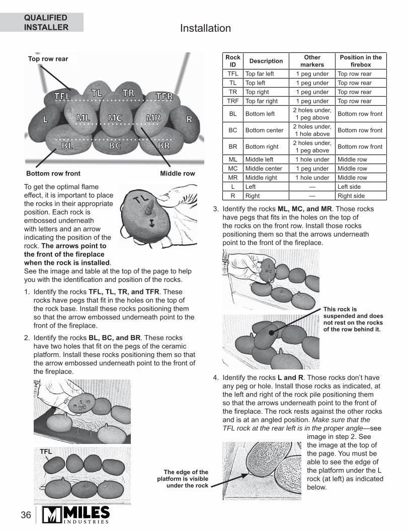
36
Installation
To get the optimal fl ame effect, it is important to place the rocks in their appropriate position. Each rock is embossed underneath with letters and an arrow indicating the position of the rock. The arrows point to the front of the fi replace when the rock is installed.See the image and table at the top of the page to help you with the identifi cation and position of the rocks.
1. Identify the rocks TFL, TL, TR, and TFR. These rocks have pegs that fi t in the holes on the top of the rock base. Install these rocks positioning them so that the arrow embossed underneath point to the front of the fi replace.
2. Identify the rocks BL, BC, and BR. These rocks have two holes that fi t on the pegs of the ceramic platform. Install these rocks positioning them so that the arrow embossed underneath point to the front of the fi replace.
3. Identify the rocks ML, MC, and MR. Those rocks have pegs that fi ts in the holes on the top of the rocks on the front row. Install those rocks positioning them so that the arrows underneath point to the front of the fi replace.
4. Identify the rocks L and R. Those rocks don’t have any peg or hole. Install those rocks as indicated, at the left and right of the rock pile positioning them so that the arrows underneath point to the front of the fi replace. The rock rests against the other rocks and is at an angled position. Make sure that the TFL rock at the rear left is in the proper angle—see
image in step 2. See the image at the top of the page. You must be able to see the edge of the platform under the L rock (at left) as indicated below.
This rock is suspended and does not rest on the rocks of the row behind it.
The edge of the platform is visible
under the rock
Rock ID Description Other
markersPosition in the
fi reboxTFL Top far left 1 peg under Top row rearTL Top left 1 peg under Top row rearTR Top right 1 peg under Top row rear
TRF Top far right 1 peg under Top row rear
BL Bottom left 2 holes under, 1 peg above Bottom row front
BC Bottom center 2 holes under, 1 hole above Bottom row front
BR Bottom right 2 holes under, 1 peg above Bottom row front
ML Middle left 1 hole under Middle rowMC Middle center 1 peg under Middle rowMR Middle right 1 hole under Middle rowL Left — Left sideR Right — Right side
TFL TFRTR
BR
R
TL
BL
MRML
BC
MCL
Bottom row front Middle row
Top row rear
TFL
QUALIFIED INSTALLER
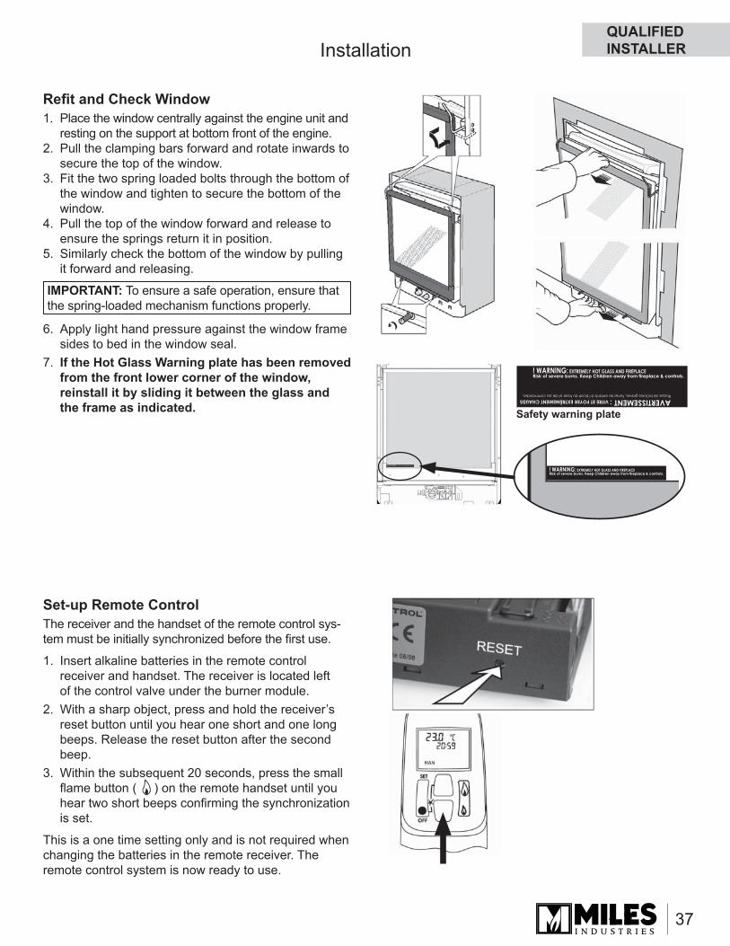
37
Installation
Refi t and Check Window1. Place the window centrally against the engine unit and
resting on the support at bottom front of the engine.2. Pull the clamping bars forward and rotate inwards to
secure the top of the window.3. Fit the two spring loaded bolts through the bottom of
the window and tighten to secure the bottom of the window.
4. Pull the top of the window forward and release to ensure the springs return it in position.
5. Similarly check the bottom of the window by pulling it forward and releasing.
6. Apply light hand pressure against the window frame sides to bed in the window seal.
7. If the Hot Glass Warning plate has been removed from the front lower corner of the window, reinstall it by sliding it between the glass and the frame as indicated.
Set-up Remote ControlThe receiver and the handset of the remote control sys-tem must be initially synchronized before the fi rst use.
1. Insert alkaline batteries in the remote control receiver and handset. The receiver is located left of the control valve under the burner module.
2. With a sharp object, press and hold the receiver’s reset button until you hear one short and one long beeps. Release the reset button after the second beep.
3. Within the subsequent 20 seconds, press the small fl ame button ( ) on the remote handset until you hear two short beeps confi rming the synchronization is set.
This is a one time setting only and is not required when changing the batteries in the remote receiver. The remote control system is now ready to use.
IMPORTANT: To ensure a safe operation, ensure that the spring-loaded mechanism functions properly.
Safety warning plate
QUALIFIED INSTALLER
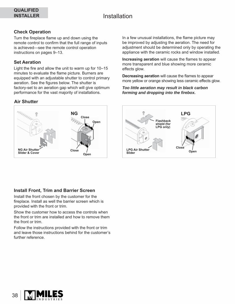
38
Installation
Open
Open
Close
CloseNG
Flashback shield (for LPG only)
LPG Air Shutter Slider Open
Close
LPG
NG Air Shutter Slider & Cover
Check OperationTurn the fi replace fl ame up and down using the remote control to confi rm that the full range of inputs is achieved—see the remote control operation instructions on pages 9–13.
Set AerationLight the fi re and allow the unit to warm up for 10–15 minutes to evaluate the fl ame picture. Burners are equipped with an adjustable shutter to control primary aeration. See the fi gures below. The shutter is factory-set to an aeration gap which will give optimum performance for the vast majority of installations.
In a few unusual installations, the fl ame picture may be improved by adjusting the aeration. The need for adjustment should be determined only by operating the appliance with the ceramic rocks and window installed.
Increasing aeration will cause the fl ames to appear more transparent and blue showing more ceramic effects glow.
Decreasing aeration will cause the fl ames to appear more yellow or orange showing less ceramic effects glow.
Too little aeration may result in black carbon forming and dropping into the fi rebox.
Air Shutter
Install Front, Trim and Barrier ScreenInstall the front chosen by the customer for the fi replace. Install as well the barrier screen which is provided with the front or trim.Show the customer how to access the controls when the front or trim are installed and how to remove them the front or trim. Follow the instructions provided with the front or trim and leave those instructions behind for the customer’s further reference.
QUALIFIED INSTALLER
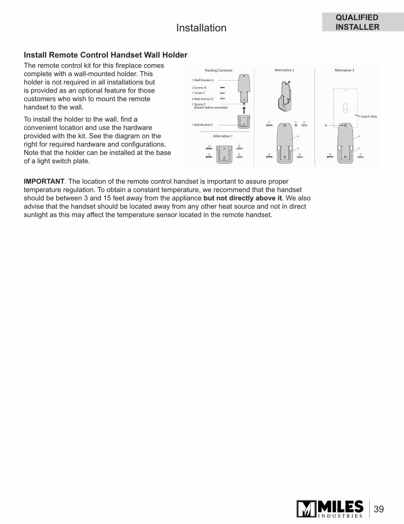
39
Packing Contents:
1 Wall Bracket A
2 Screws B
1 Screw C
2 Wall Anchor D
1 Spacer E (detach before assembly)
1 Wall Bracket F
Switch Plate
Alternative 1
Alternative 2 Alternative 3
Installation
Install Remote Control Handset Wall HolderThe remote control kit for this fi replace comes complete with a wall-mounted holder. This holder is not required in all installations but is provided as an optional feature for those customers who wish to mount the remote handset to the wall.
To install the holder to the wall, fi nd a convenient location and use the hardware provided with the kit. See the diagram on the right for required hardware and confi gurations. Note that the holder can be installed at the base of a light switch plate.
IMPORTANT. The location of the remote control handset is important to assure proper temperature regulation. To obtain a constant temperature, we recommend that the handset should be between 3 and 15 feet away from the appliance but not directly above it. We also advise that the handset should be located away from any other heat source and not in direct sunlight as this may affect the temperature sensor located in the remote handset.
QUALIFIED INSTALLER
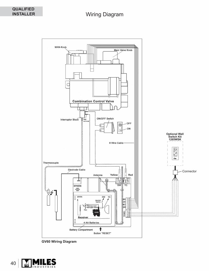
40
Wiring Diagram
Optional Wall Switch Kit 1265WSK
ConnectorRedYellow
GV60 Wiring Diagram
QUALIFIED INSTALLER
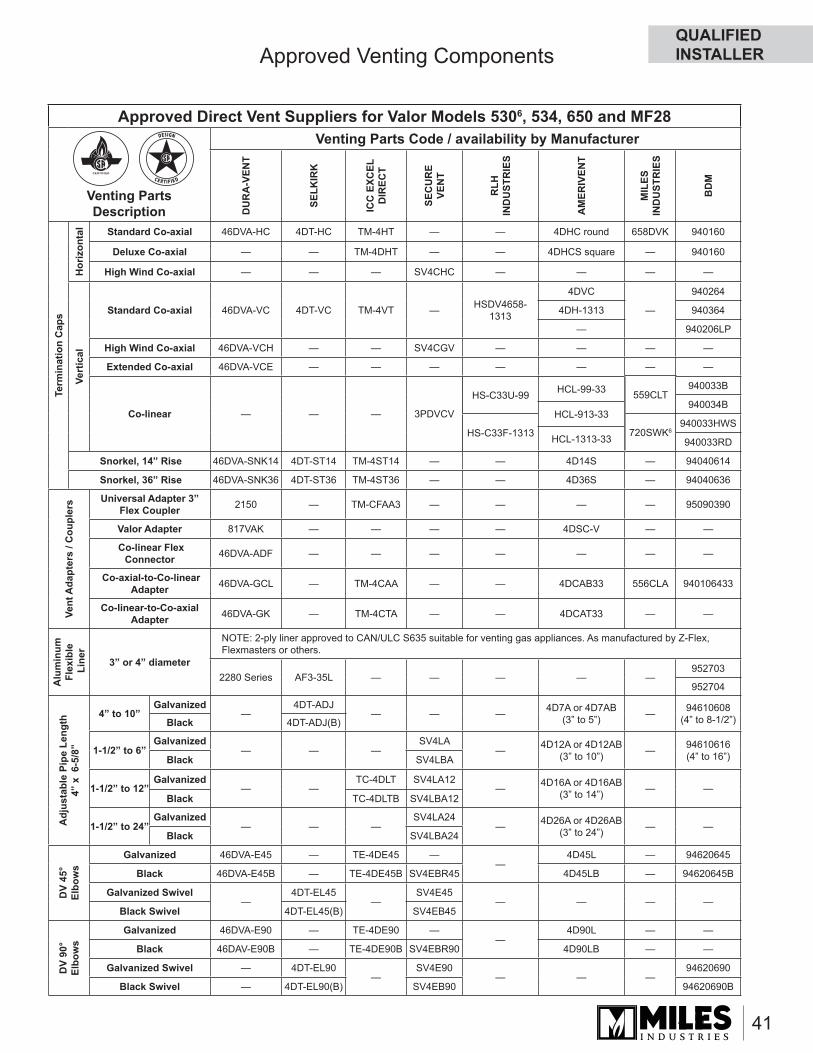
41
Approved Venting Components
Approved Direct Vent Suppliers for Valor Models 5306, 534, 650 and MF28
Venting Parts Description
Venting Parts Code / availability by Manufacturer
DU
RA
-VEN
T
SELK
IRK
ICC
EXC
EL
DIR
ECT
SEC
UR
E VE
NT
RLH
IN
DU
STR
IES
AM
ERIV
ENT
MIL
ES
IND
UST
RIE
S
BD
M
Term
inat
ion
Cap
s
Hor
izon
tal Standard Co-axial 46DVA-HC 4DT-HC TM-4HT — — 4DHC round 658DVK 940160
Deluxe Co-axial — — TM-4DHT — — 4DHCS square — 940160
High Wind Co-axial — — — SV4CHC — — — —
Vert
ical
Standard Co-axial 46DVA-VC 4DT-VC TM-4VT — HSDV4658-1313
4DVC
—
940264
4DH-1313 940364
— 940206LP
High Wind Co-axial 46DVA-VCH — — SV4CGV — — — —
Extended Co-axial 46DVA-VCE — — — — — — —
Co-linear — — — 3PDVCV
HS-C33U-99 HCL-99-33 940033B
HS-C33F-1313 HCL-913-33 940034B
— HCL-1313-33 940033HWS
— — 940033RD
Snorkel, 14” Rise 46DVA-SNK14 4DT-ST14 TM-4ST14 — — 4D14S — 94040614
Snorkel, 36” Rise 46DVA-SNK36 4DT-ST36 TM-4ST36 — — 4D36S — 94040636
Vent
Ada
pter
s / C
oupl
ers Universal Adapter 3”
Flex Coupler 2150 — TM-CFAA3 — — — — 95090390
Valor Adapter 817VAK — — — — 4DSC-V — —
Co-linear Flex Connector 46DVA-ADF — — — — — — —
Co-axial-to-Co-linear Adapter 46DVA-GCL — TM-4CAA — — 4DCAB33 556CLA 940106433
Co-linear-to-Co-axialAdapter 46DVA-GK — TM-4CTA — — 4DCAT33 — —
Alu
min
um
Flex
ible
Lin
er
3” or 4” diameter
NOTE: 2-ply liner approved to CAN/ULC S635 suitable for venting gas appliances. As manufactured by Z-Flex, Flexmasters or others.
2280 Series AF3-35L — — — — —952703
952704
Adj
usta
ble
Pipe
Len
gth
4” x
6-5
/8”
4” to 10”Galvanized
— 4DT-ADJ
— — — 4D7A or 4D7AB(3” to 5”) — 94610608
(4” to 8-1/2”)Black 4DT-ADJ(B)
1-1/2” to 6”Galvanized
— — — SV4LA
— 4D12A or 4D12AB(3” to 10”) — 94610616
(4” to 16”)Black SV4LBA
1-1/2” to 12”Galvanized
— — TC-4DLT SV4LA12
— 4D16A or 4D16AB(3” to 14”) — —
Black TC-4DLTB SV4LBA12
1-1/2” to 24”Galvanized
— — — SV4LA24
— 4D26A or 4D26AB(3” to 24”) — —
Black SV4LBA24
DV
45°
Elbo
ws
Galvanized 46DVA-E45 — TE-4DE45 — —
4D45L — 94620645
Black 46DVA-E45B — TE-4DE45B SV4EBR45 4D45LB — 94620645B
Galvanized Swivel—
4DT-EL45—
SV4E45— — — —
Black Swivel 4DT-EL45(B) SV4EB45
DV
90°
Elbo
ws
Galvanized 46DVA-E90 — TE-4DE90 — —
4D90L — —
Black 46DAV-E90B — TE-4DE90B SV4EBR90 4D90LB — —
Galvanized Swivel — 4DT-EL90—
SV4E90— — —
94620690
Black Swivel — 4DT-EL90(B) SV4EB90 94620690B
HS-C33U-99
HS-C33F-1313
559CLT
720SWK6
HCL-99-33
HCL-913-33
HCL-1313-33
QUALIFIED INSTALLER
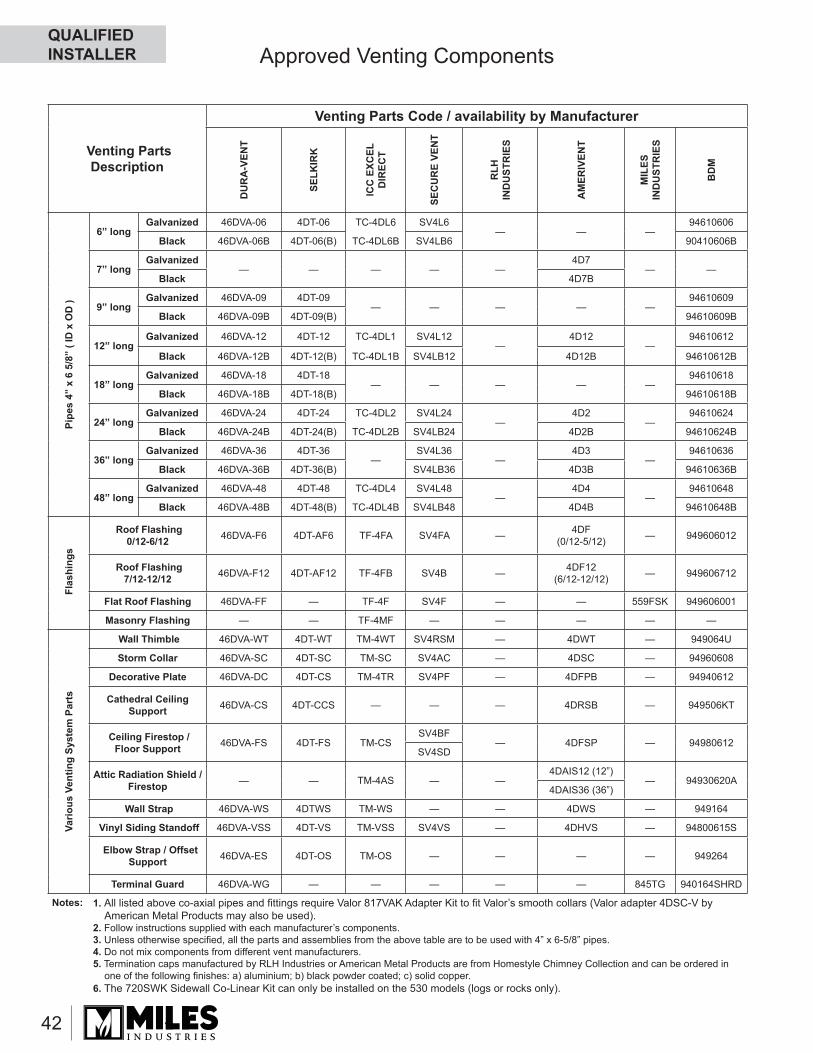
42
Approved Venting Components
Venting Parts Description
Venting Parts Code / availability by Manufacturer
DU
RA
-VEN
T
SELK
IRK
ICC
EXC
EL
DIR
ECT
SEC
UR
E VE
NT
RLH
IN
DU
STR
IES
AM
ERIV
ENT
MIL
ES
IND
UST
RIE
S
BD
M
Pipe
s 4”
x 6
5/8
” ( I
D x
OD
)
6” longGalvanized 46DVA-06 4DT-06 TC-4DL6 SV4L6
— — — 94610606
Black 46DVA-06B 4DT-06(B) TC-4DL6B SV4LB6 90410606B
7” longGalvanized
— — — — —4D7
— —Black 4D7B
9” longGalvanized 46DVA-09 4DT-09
— — — — — 94610609
Black 46DVA-09B 4DT-09(B) 94610609B
12” longGalvanized 46DVA-12 4DT-12 TC-4DL1 SV4L12
— 4D12
— 94610612
Black 46DVA-12B 4DT-12(B) TC-4DL1B SV4LB12 4D12B 94610612B
18” longGalvanized 46DVA-18 4DT-18
— — — — — 94610618
Black 46DVA-18B 4DT-18(B) 94610618B
24” longGalvanized 46DVA-24 4DT-24 TC-4DL2 SV4L24
— 4D2
— 94610624
Black 46DVA-24B 4DT-24(B) TC-4DL2B SV4LB24 4D2B 94610624B
36” longGalvanized 46DVA-36 4DT-36
— SV4L36
— 4D3
— 94610636
Black 46DVA-36B 4DT-36(B) SV4LB36 4D3B 94610636B
48” longGalvanized 46DVA-48 4DT-48 TC-4DL4 SV4L48
— 4D4
— 94610648
Black 46DVA-48B 4DT-48(B) TC-4DL4B SV4LB48 4D4B 94610648B
Fla
shin
gs
Roof Flashing0/12-6/12 46DVA-F6 4DT-AF6 TF-4FA SV4FA — 4DF
(0/12-5/12) — 949606012
Roof Flashing7/12-12/12 46DVA-F12 4DT-AF12 TF-4FB SV4B — 4DF12
(6/12-12/12) — 949606712
Flat Roof Flashing 46DVA-FF — TF-4F SV4F — — 559FSK 949606001
Masonry Flashing — — TF-4MF — — — — —
Vario
us V
entin
g Sy
stem
Par
ts
Wall Thimble 46DVA-WT 4DT-WT TM-4WT SV4RSM — 4DWT — 949064U
Storm Collar 46DVA-SC 4DT-SC TM-SC SV4AC — 4DSC — 94960608
Decorative Plate 46DVA-DC 4DT-CS TM-4TR SV4PF — 4DFPB — 94940612
Cathedral Ceiling Support 46DVA-CS 4DT-CCS — — — 4DRSB — 949506KT
Ceiling Firestop / Floor Support 46DVA-FS 4DT-FS TM-CS
SV4BF— 4DFSP — 94980612
SV4SD
Attic Radiation Shield / Firestop — — TM-4AS — —
4DAIS12 (12”)— 94930620A
4DAIS36 (36”)
Wall Strap 46DVA-WS 4DTWS TM-WS — — 4DWS — 949164
Vinyl Siding Standoff 46DVA-VSS 4DT-VS TM-VSS SV4VS — 4DHVS — 94800615S
Elbow Strap / Offset Support 46DVA-ES 4DT-OS TM-OS — — — — 949264
Terminal Guard 46DVA-WG — — — — — 845TG 940164SHRD
Notes: 1. All listed above co-axial pipes and fi ttings require Valor 817VAK Adapter Kit to fi t Valor’s smooth collars (Valor adapter 4DSC-V by American Metal Products may also be used).
2. Follow instructions supplied with each manufacturer’s components. 3. Unless otherwise specifi ed, all the parts and assemblies from the above table are to be used with 4” x 6-5/8” pipes. 4. Do not mix components from different vent manufacturers.5. Termination caps manufactured by RLH Industries or American Metal Products are from Homestyle Chimney Collection and can be ordered in
one of the following fi nishes: a) aluminium; b) black powder coated; c) solid copper.6. The 720SWK Sidewall Co-Linear Kit can only be installed on the 530 models (logs or rocks only).
QUALIFIED INSTALLER
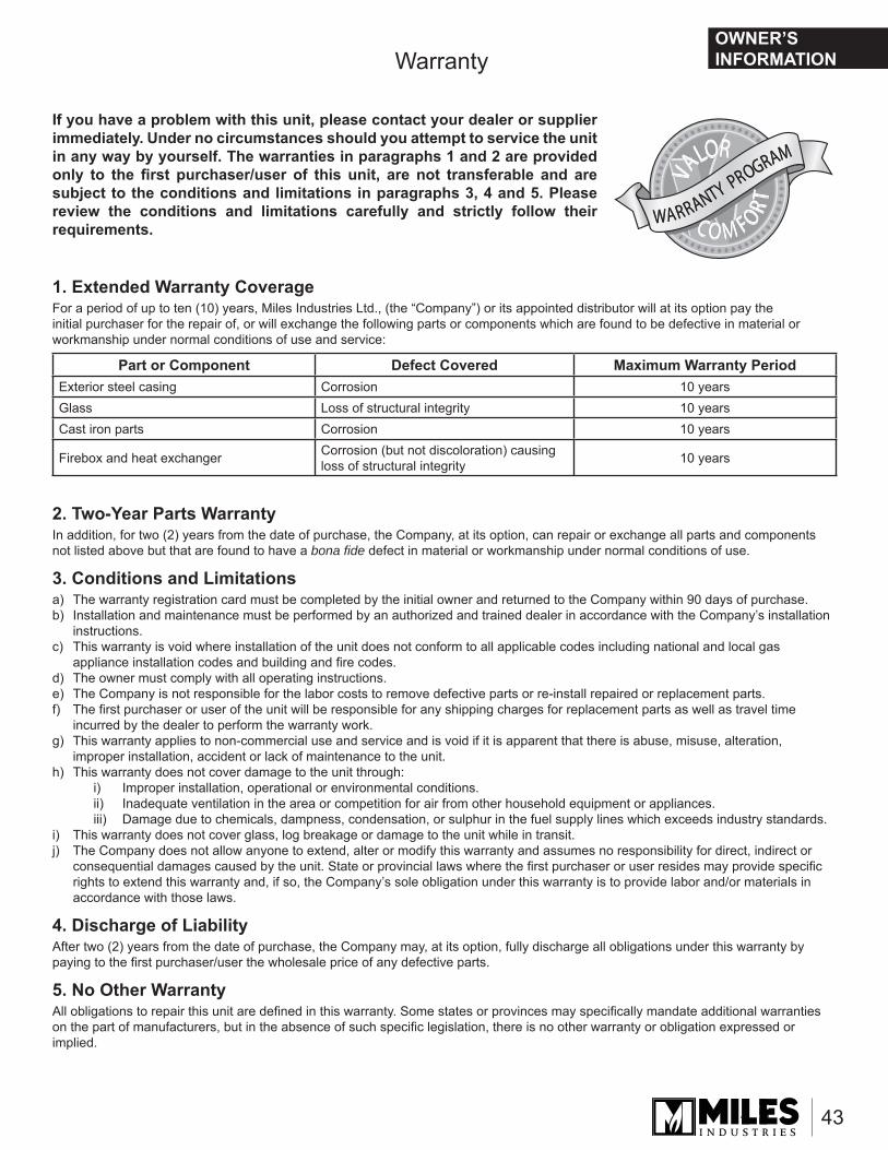
43
Warranty
1. Extended Warranty CoverageFor a period of up to ten (10) years, Miles Industries Ltd., (the “Company”) or its appointed distributor will at its option pay the initial purchaser for the repair of, or will exchange the following parts or components which are found to be defective in material or workmanship under normal conditions of use and service:
2. Two-Year Parts Warranty In addition, for two (2) years from the date of purchase, the Company, at its option, can repair or exchange all parts and components not listed above but that are found to have a bona fi de defect in material or workmanship under normal conditions of use.
3. Conditions and Limitationsa) The warranty registration card must be completed by the initial owner and returned to the Company within 90 days of purchase.b) Installation and maintenance must be performed by an authorized and trained dealer in accordance with the Company’s installation
instructions.c) This warranty is void where installation of the unit does not conform to all applicable codes including national and local gas
appliance installation codes and building and fi re codes.d) The owner must comply with all operating instructions.e) The Company is not responsible for the labor costs to remove defective parts or re-install repaired or replacement parts.f) The fi rst purchaser or user of the unit will be responsible for any shipping charges for replacement parts as well as travel time
incurred by the dealer to perform the warranty work.g) This warranty applies to non-commercial use and service and is void if it is apparent that there is abuse, misuse, alteration,
improper installation, accident or lack of maintenance to the unit.h) This warranty does not cover damage to the unit through:
i) Improper installation, operational or environmental conditions.ii) Inadequate ventilation in the area or competition for air from other household equipment or appliances.iii) Damage due to chemicals, dampness, condensation, or sulphur in the fuel supply lines which exceeds industry standards.
i) This warranty does not cover glass, log breakage or damage to the unit while in transit.j) The Company does not allow anyone to extend, alter or modify this warranty and assumes no responsibility for direct, indirect or
consequential damages caused by the unit. State or provincial laws where the fi rst purchaser or user resides may provide specifi c rights to extend this warranty and, if so, the Company’s sole obligation under this warranty is to provide labor and/or materials in accordance with those laws.
4. Discharge of LiabilityAfter two (2) years from the date of purchase, the Company may, at its option, fully discharge all obligations under this warranty by paying to the fi rst purchaser/user the wholesale price of any defective parts.
5. No Other WarrantyAll obligations to repair this unit are defi ned in this warranty. Some states or provinces may specifi cally mandate additional warranties on the part of manufacturers, but in the absence of such specifi c legislation, there is no other warranty or obligation expressed or implied.
Part or Component Defect Covered Maximum Warranty PeriodExterior steel casing Corrosion 10 yearsGlass Loss of structural integrity 10 yearsCast iron parts Corrosion 10 years
Firebox and heat exchanger Corrosion (but not discoloration) causing loss of structural integrity 10 years
WARRANTY PROGRAM
WARRANTY PROGRAM
VA
LOR
C O M F ORT
VA
LOR
C O M F ORT
VA
LOR
C O M F ORT
If you have a problem with this unit, please contact your dealer or supplier immediately. Under no circumstances should you attempt to service the unit in any way by yourself. The warranties in paragraphs 1 and 2 are provided only to the fi rst purchaser/user of this unit, are not transferable and are subject to the conditions and limitations in paragraphs 3, 4 and 5. Please review the conditions and limitations carefully and strictly follow their requirements.
OWNER’S INFORMATION
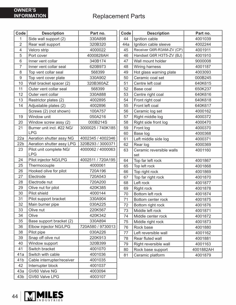
44
Replacement Parts
Code Description Part no.1 Side wall support (2) 330A8982 Rear wall support 320B3204 Velcro strip 40000225 Port cover 4000828AH6 Inner vent collar 340B1747 Inner vent collar seal 620B9738 Top vent collar seal 5683999 Top vent cover plate 330A902
10 Wall bracket spacer (2) 320B360AZ11 Outer vent collar seal 56839912 Outer vent collar 330A88813 Restrictor plates (2) 400289514 Adjustable plates (2) 4002896
Screws (2) (not shown) 100A75719 Window unit 050A21620 Window screw assy (2) 000B214S21 Burner unit incl. #22 NG/
LPG3000025 / 740K185
22a Aeration shutter assy NG 4002345 / 400234622b Aeration shutter assy LPG 320B293 / 300037123 Pilot unit complete NG/
LPG4000062 / 4000063
24 Pilot injector NG/LPG 4002511 / 720A19525 Thermocouple 400006126 Hooked olive for pilot 720A19627 Electrode 720A54328 Electrode nut 720A20029 Olive nut for pilot 420K38530 Pilot shield 400014431 Pilot support bracket 330A90432 Main burner pipe 030A22533 Olive nut 220K56734 Olive 420K34235 Base support bracket (2) 330A89436 Elbow injector NG/LPG 720A580 / 973001338 Pilot pipe 030A22639 Snap off olive nut 220K91340 Window support 320B39941 Switch bracket 4001070
41a Switch with cable 400103641b Cable interrupter/receiver 400103542 Interrupter block 4001037
43a GV60 Valve NG 400309443b GV60 Valve LPG 4003107
Code Description Part no.44 Ignition cable 4001039
44a Ignition cable sleeve 400224445 Receiver G6R-R3AM-ZV (CP) 400191146 Handset G6R H3T5-ZV (BJ) 400191047 Wall mount holder 900000848 Wiring harness 400118749 Hot glass warning plate 400309350 Ceramic coal set 000B24551 Centre left coal 640K61552 Base coal 650K23753 Centre right coal 640K61654 Front right coal 640K61855 Front left coal 640K61756 Ceramic log set 400016257 Right middle log 400037258 Right side front log 400047059 Front log 400037060 Base log 400036861 Left middle side log 400037162 Rear log 400036963 Ceramic reversible walls
set4001160
64 Top far left rock 400186765 Top left rock 400186866 Top right rock 400186967 Top far right rock 400187068 Left rock 400187769 Right rock 400187870 Bottom left rock 400187471 Bottom center rock 400187572 Bottom right rock 400187673 Middle left rock 400187174 Middle center rock 400187275 Middle right rock 400187376 Rock base 400188077 Left reversible wall 400116278 Rear fl uted wall 400188179 Right reversible wall 400116380 Rock base support 4001882AH81 Ceramic platform 4001879
OWNER’S INFORMATION
45
1
2
4
5
6
7
8
9
1011
12
13
14
19
20
21 22a22b
23
24
25
26
27
28
29
30
31
33
32
3435
36
38
39
40
41
42 44
43a, 43b
45
46
47
48
41a41b
NG
LPG
16a16b
15a 15b
Replacement Parts
44a
49
OWNER’S INFORMATION
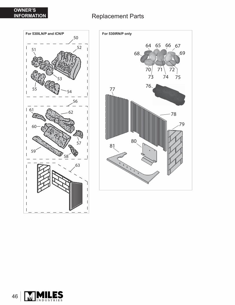
46
51 52
53
5455
56
57
5859
60
61 62
63
50
Replacement Parts
64 65 66 6769
7371
7472
75
7677
78
79
8081
70
68
For 530IRN/P onlyFor 530ILN/P and ICN/P
OWNER’S INFORMATION
Thank You ...For purchasing a Valor by Miles Industries. Your new radiant gas heater is a technical appliance that must be installed by a qualifi ed installer.Please fi ll in the information below. The information provided will be used for customer records only.
Online Warranty registration at www.valorfi replaces.com
Cut out page, fi ll information, and mail to Miles Industries Ltd.
Fireplace Information
Model Number: 530I LN LP CN CP RN or RP
Serial Number:
Date Purchase (yyyy-mm-dd):
Dealer:
Customer Information
First Name:
Last Name:
Contact Information
Email:
Mailing Address
Address:
City:
Province/State:
Postal/Zip Code:
Country:
Tape Shut
Thank you for choosing a Valor Product
Postageneeded
Miles Industries Ltd.190 - 2255 Dollarton HighwayNorth Vancouver, BC V7H 3B1 Canada
Fold here
Online Warranty registration at www.valorfi replaces.com