DustBoss Manual (2)
33
DB- 30 DB- 60 innovative patented products by: OPERATING & PARTS MANUAL Rev. 12/07
-
Upload
michael-huffman -
Category
Documents
-
view
167 -
download
5
description
manual for dust boss system
Transcript of DustBoss Manual (2)

DB-30DB-60
innovative patented products by:
OPERATING & PARTS MANUAL
Rev. 12/07

i
IMPORTANT
DUST CONTROL TECHNOLOGY, INC., HEREBY DISCLAIMS ANY LIABILITY FOR: DAMAGE DUE TO CONTAMINATIONOF THE MATERIAL; USER’S FAILURE TO INSPECT, MAINTAIN AND TAKE REASONABLE CARE OF THE EQUIPMENT;INJURIES OR DAMAGE RESULTING FROM USE OR APPLICATION OF THIS PRODUCT CONTRARY TO INSTRUCTIONSAND SPECIFICATIONS CONTAINED HEREIN. DUST CONTROL TECHNOLOGY’S® LIABILITY SHALL BE LIMITED TOREPAIR OR REPLACEMENT OF EQUIPMENT SHOWN TO BE DEFECTIVE.
Observe all safety rules given herein along with owner and Government standards and regulations. Know and understandlockout/tagout procedures as defined by American National Standards Institute (ANSI) z244.1-1982, American NationalStandard for Personnel Protection - Lockout/Tagout of Energy Sources - Minimum Safety Requirements andOccupational Safety and Health Administration (OSHA) Federal Register, Part IV, 29 CFR Part 1910, Control ofHazardous Energy Source (Lockout/Tagout); Final Rule.
THE FOLLOWING SYMBOLS MAY BE USED IN THIS MANUAL:
DANGER: Immediate hazards that will result in severe personal injury or death.
WARNING: Hazards or unsafe practices that could result in personal injury.
CAUTION: Hazards or unsafe practices that could result in product or property damages.
IMPORTANT: Instructions that must be followed to ensure proper installation/operation of equipment.
NOTE: General statements to assist the reader.
THE FOLLOWING DOCUMENTS ARE REFERENCED IN THIS MANUAL:
> American National Standards Institute (ANSI) z244.1-1982, American National Standard for Personnel Protection - Lockout/Tagout of Energy
Sources - Minimum Safety Requirements, American National Standards Institute, Inc., 1430 Broadway, New York, NY 10018.
> Federal Register, Volume 54, Number 169, Part IV, 29 CFR Part 1910, Control of Hazardous Energy Source (Lockout/Tagout);
Final Rule, Department of Labor, Occupational Safety and Health Administration (OSHA), 32nd Floor, Room 3244,
230 South Dearborn Street, Chicago, IL 60604.
> The National Electrical Code (NEC) Handbook, National Fire Protection Association, 1 Batterymarch Park, P.O. Box 9101,
Quincy MA 02269-9101.
> ICS 1-1988, General Standards for Industrial Control and Systems, and 250-1985, Enclosures for Electrical Equipment
(1000 Volts Maximum), National Electrical Manufacturers Association (NEMA), 2101 L Street N.W., Washington, D.C. 20037.

ii
TABLE OF CONTENTS
SECTION PAGEIMPORTANT ..................................................................................................................................................................................................i
INTRODUCTION
> General ..........................................................................................................................................................................................................1
> Description ....................................................................................................................................................................................................1
> DB-30 Operating Requirements & Technical Specifications ......................................................................................................2–3
> DB-30 Operating Requirements & Technical Specifications ......................................................................................................3–5
TRAINING & SAFETY
> Safety ..............................................................................................................................................................................................................6
> Materials Required......................................................................................................................................................................................6
> Training ..........................................................................................................................................................................................................6
> Precautions ................................................................................................................................................................................................6–7
BEFORE INSTALLATION
> Before Using Your DustBoss® ................................................................................................................................................................8
OPERATING THE UNIT
> Safety ..............................................................................................................................................................................................................8
> Control Panel ................................................................................................................................................................................................8
> Unit Startup ..................................................................................................................................................................................................8
> Unit Shutdown ............................................................................................................................................................................................9
> Aiming the DustBoss® ..............................................................................................................................................................................9
HANDLING YOUR UNIT
> Transport & Positioning ............................................................................................................................................................................10
> DB-30 Machine Pivoting & Head Adjustment ..............................................................................................................................10–11
> DB-60 Machine Pivoting & Head Adjustment ..............................................................................................................................11–12
STORAGE & MAINTENANCE
> Machine Storage & Placement Options ............................................................................................................................................13
> Winterizing Rules ......................................................................................................................................................................................13
> Daily Checklist ............................................................................................................................................................................................13
> Quarterly Maintenance Checklist ..........................................................................................................................................................14
REMINDERS
> Do’s, Don’ts & Remembers....................................................................................................................................................................15
ADDITIONAL RESOURCES
> Appendix of Figures ..................................................................................................................................................................................17
> Optional Booster Pump Information ................................................................................................................................................18–23
> DustBoss® Parts List..............................................................................................................................................................................24–28
WARRANTY..................................................................................................................................................................................................29

1
INTRODUCTION
Your DustBoss® Dust Controller has been designed for maximum throw while breakingwater into fine droplets to allow maximum dust control.
The DustBoss® units were designed for hostile industrial environments. Simplicity ofdesign, ease of operation and maintenance are their key features. As you become morefamiliar with your machine and its great versatility, you will appreciate the difference yourDustBoss® can make to create a cleaner, safer environment.
The DB-30 uses fan and nozzle technology to mist 5,500 sq.ft. (511 sq. meters) of areaautomatically. The DB-60 uses the same technology to cover 21,000 sq. ft. (1,950 sq. meters)with a fine mist. Considerable effort has gone into the research; testing and actual usehave provided insight into the design and improvements to the DustBoss® units.
Dust Control Technology® is dedicated to providing our customers with superior qualityproducts for optimum trouble-free operation.
It is important that you have a full understanding of the contents of this manual. It containsinformation which will help you operate your DustBoss® in a safe manner and obtain optimum performance from the system.
The DustBoss® units utilize a ducted fan with an efficient water spray manifold and nozzle system.
The most effective dust control is attained by using higher water pressures (up to 150 PSI; or 10.34 BAR) and the proper location of the unit to use the wind to your advantage. The spray manifold consists of a main water manifold with 30 nozzles. A simple quick disconnect system allows the feed hose to be easily connected.
A 3-wheel carriage system is utilized for both units. A control panel and 100 foot (30.48 meter)cord are used to safely power the DB-30. The DB-60 is safely powered with a stainless steelcontrol panel and 150 foot (45.72 meter) cord.
Intensive effort and research have gone into creating a safe and efficient dust controller. If you have any questions on the operation of the equipment after reviewing this manual,please contact your local representative or call Dust Control Technology® directly at 800-707-2204 or 309-693-8600. In case of emergency, please call anytime, 24/7.
GENERAL
DESCRIPTION
DB-60 (left)
DB-30 (right)

2
OPERATINGREQUIREMENTS
DB-30
TECHNICALSPECIFICATIONS
DB-30
SPECIFICATIONS
Standard Electrical Service
> U.S.: 480 Volt / 60 Hertz / 3 Phase / 60 Amp Breaker(Metric: 400 Volt / 50 Hertz / 3 Phase / 60 Amp Breaker)
> The motors have been designed with a 1.1 service factor capable of operating at ± 10% of design voltage.
> Options available: • 220 Volt - Single Phase
> Other motor options available upon request.
Water
> 1.4–2.8 GPM (5.3–10.6 LPM) / 15 PSI (1.034 BAR) minimum to 100 PSI (6.89 BAR) maximum.
General Specifications
> 9,200 CFM (260.5 CMM) generated by 7.5 HP fan. U.S.: 480 Volt, 60 Hertz, 3 Phase (Metric: 400 Volt, 50 Hertz, 3 Phase).
> 8,000 CFM (226.5 CMM) air for optional single phase motor.
> 5,500 square feet (511 square meters) coverage.
> Oscillator gives 0–70 degrees of movement.
> Adjustable angle of throw 0–50 degrees of height adjustment.
Electrical Specifications
> Motors are designed with a 1.1 service factor capable of operating at +/- 10% of design voltage.
> U.S.: 3 Phase / 7.5 HP / 480 Volt, 60 Hertz (Metric: 3 Phase / 5.5 Kw / 400 Volt, 50 Hertz)Full load current is 11 amps. Recommended minimum gen set is 30 Kw.
> OPTIONAL — U.S.: Single Phase / 5 HP / 220 Volt. Full load current is 28 amps.
> 1/8 HP (0.1 Kw) oscillator.
> 100 foot (30.48 meters) electrical cord.
> UL-Listed cabinet with control panel.
> All international electrical motors available.
Water Specifications
> 15 PSI (1.034 BAR) minimum constant pressure needs to be delivered to DB-30.
> Do not operate above 150 PSI (10.34 BAR) water pressure or the unit may be damaged.
> Standard 5/8" (15.8 mm) garden hose connection.
> 30 brass nozzles (also available in stainless and nylon).
> Droplet size of 50–200 microns.
> Throw 100 feet (30 m).

3
Ambient Environmental Specifications
Temperature Range: 32º–122º F (0º–50º C)
Altitude Range: 0–9,842 feet (0–3,000 meters)
Relative Humidity: 0 to 100%
Vibration: If you experience unusual noise or vibration, shut the machinedown immediately and contact your local representative or Dust Control Technology® directly at 800-707-2204 or 309-693-8600. In case of emergency, please call anytime, 24/7.
Dimensions
> 5.2 feet (61 inches; or 1.6 meters) wide.
> 8.5 feet (102 inches; or 2.6 meters) long.
> 5.3 feet (62 inches; or 1.6 meters) tall.
> 800 lbs (363 Kilograms).
Maintenance
> Fan motor greased every 10,000 hours.
> Oscillator greased for life.
Optional
> Dosing Pump can be added to the unit for odor control.
> Surfactant can be used to improve binding of dust particles.
> Odor control chemicals can be used to assist in the elimination of odor.
> Unit can be equipped with an explosion-proof motor and/or filter system.
Standard Electrical Service
> U.S.: 480 Volt / 60 Hertz / 3 Phase / 60 Amp Breaker (Metric: 400 Volt / 50 Hertz / 3 Phase / 60 Amp Breaker).
> The motors have been designed with a 1.3 service factor capable of operating at ± 10% of design voltage.
> Options available:
• 380 Volt / 3 Phase / 50 Hertz (Europe, Middle East, Northern Japan, Latin America)
• 400 Volt / 3 Phase / 50 Hertz (Japan, Korea, New Zealand and Australia)
• 415 Volt – 51 Amps / 400 V – 51 Amps / 380 V – 54 Amps
• 575 Volt / 3 Phase / 60 Hertz (Eastern Canada)
> Other motor options available upon request.
Water
> 15 GPM (56.8 LPM) / 10 PSI minimum (0.689 BAR) to 150 PSI (10.34 BAR) maximum.
TECHNICALSPECIFICATIONS
DB-30(continued)
OPERATINGREQUIREMENTS
DB-60

4
General Specifications
> 30,000 CFM (849.5 CMM) generated by fan.
> 21,000 square feet (1,950 square meters) coverage.
> Oscillator gives 0–40 degrees of movement.
> Adjustable angle of throw 0–50 degrees of height adjustment.
Electrical Specifications
> Motors are designed with a 1.3 service factor capable of operating at +/- 10% of design voltage.
> U.S.: 3 Phase / 7.5 HP / 480 Volt, 60 Hertz (Metric: 3 Phase / 5.5 Kw / 400 Volt, 50 Hertz).Full load current is 46 amps. 60 Kw gen set is recommended.
> 25 HP fan (19 Kw).
> 10 HP (7.5 Kw) high pressure booster pump with no lift.
> 1/8 HP (0.1 Kw) oscillator.
> 150 foot (46 meters) electrical cord.
> UL-Listed stainless steel cabinet.
> All international electrical motors available.
Water Specifications
> 10 PSI (0.689 BAR) minimum constant pressure needs to be delivered to booster pump.
> Water boosted by 150 PSI (10.34 BAR) after going through booster pump.
> Source plus 150 PSI (10.34 BAR) equal total and should not exceed 300 PSI (20.68 BAR).
> Filter included and should be used for potable and nonpotable water. (Filter system in-line 30 mesh 595 micron).
> 10 GPM (37.9 LPM) / 10 PSI (0.689 BAR) minimum to 150 PSI (10.34 BAR) maximum.
> 1-1/2" (38.1 mm) cam-and-groove quick disconnect female coupling for fire hose provided on machine.
> 30 brass nozzles (also available in stainless and nylon).
> Droplet size 50–200 microns.
> Throw 200 feet (60 m).
TECHNICALSPECIFICATIONS
DB-60

5
Ambient Environmental Specifications
Temperature Range: 32º–122º F (0º–50º C)
Altitude Range: 0–9,842 feet (0–3000 meters)
Relative Humidity: 0 to 100%
Vibration: If you experience unusual noise or vibration, shut the machinedown immediately and contact your local representative or Dust Control Technology® directly at 800-707-2204 or 309-693-8600. In case of emergency, please call anytime, 24/7.
Dimensions
> 6.75 feet (81 inches; or 2.06 meters) wide.
> 9 feet (108 inches; or 2.97 meters) long.
> 6 feet (72 inches; or1.8 meters) tall.
> 1800 lbs. (816.5 Kilograms).
Maintenance
> If using potable water, nozzles need to be inspected once a year.
> Fan motor and high pressure pump greased every 10,000 hours.
> Oscillator greased for life.
Optional
> Dosing Pump can be added to the unit for odor control.
> Surfactant can be used to improve binding of dust particles.
> Odor control chemicals can be used to assist in the elimination of odor.
> Unit can be equipped with an explosion-proof motor and/or filter system.
TECHNICALSPECIFICATIONS
DB-60(continued)

6
TRAINING & SAFETY
All safety rules defined in the above documents, and all owner/employer safety rules,must be strictly followed when installing and servicing this equipment.
Materials other than standard hand tools that are required to complete tasks are listedwhere applicable. The DustBoss® should be operated only by personnel who have knowledgeof the equipment and safety and operating procedures. This will prevent mishaps or injuryand will make dust control more efficient.
Operators should have a thorough understanding of the SAFETY procedures as well ashow to operate and handle problems that might occur.
They must know where the manual is located, how to use it for reference, and how touse the checklist prior to starting the DustBoss®.
Your company is advised to develop custom training programs for your situations, and all
personnel associated with operating this equipment should receive instruction.
FOLLOW electrical guidelines at all times to avoid injury or death.
BE CERTAIN the “feed” power service and all power switches on the machine are OFFbefore connecting or disconnecting the electrical plug. ELECTRICAL SHOCK CAN BE FATAL.
BE CERTAIN that the connection to the generator is made by a certified electrician and thegenerator in grounded with a grounding rod. ELECTRICAL SHOCK CAN BE FATAL.
DO NOT open or work inside an electrical panel with the power source ON or CONNECTED.ELECTRICAL SHOCK CAN BE FATAL.
LOOSE CLOTHING SHOULD NOT BE WORN when operating the DustBoss® to prevent entangling in rotating equipment.
ALWAYS STAND OUT OF THE AIRSTREAM when starting, making adjustments, or while themachine is running. This procedure is to prevent injury from possible flying foreign material.
STAND BEHIND water feeding valve/hydrant to open or close the water valve so that incase of hose or connector failure, injury may be prevented.
ALWAYS open or close water valves VERY SLOWLY to gradually equalize the line and systempressure to prevent hose, connector or pressurized system failure. Rapid opening andclosing of water valves releases a tremendous amount of energy and could cause a failurein any part of the total pressurized system or serious personal injury.
NEVER straddle a hose as serious injury could result.
DO NOT attempt to remove ice from fan or screen and DO NOT perform mechanical orelectrical service while the machine is in operation. NEVER run the machine without thescreen and guard in place.
DO NOT shut the water valve off while the booster pump is running (DB-60 only).
TRAINING
PRECAUTIONS
SAFETY
MATERIALS REQUIRED

7
DO NOT run over the fire hose that supplies water to the DustBoss®. This can cause thehigh pressure pump to trip out and shut the unit off. Protect the water supply with boards on both sides of the hose.
NEVER move the DustBoss® until the power service is OFF, and the power cord andhoses are DISCONNECTED.
DO NOT leave hoses and cords laying around. They can possibly cause injury if run over.
DO NOT use clogged or damaged nozzles. Clogged nozzles cause erratic spray patternsthat decrease efficiency.
MONITOR THE MACHINE frequently to determine if problems are developing that couldcause personal injury, machine damage or unnecessary downtime.
FOR WINTER OPERATION, be cautious of ice, snow, wet, slippery conditions and otherhazards in the area.
NEVER place limbs or other body parts into the fan housing.
RULES FOR SAFE OPERATION
The manual should be read by all personnel associated
with misting.
> All personnel should be familiar with the machine and
be versed in their area's safety procedures.
> Moving the machine while operating is not recommended.
> Operators should exercise caution while operating the
DustBoss®. Care should be taken with clothing (i.e., scarves,
hats, hair, loose jackets, etc.) when working with any
rotating equipment.
> Always open and close hydrants/valves slowly. Rapid opening
and closing could damage the equipment, pipes and pumps,
or cause serious injury.
> Determine if appropriate signing or fencing of machine is
needed and in place.
The DustBoss® is only intended for use as a dust and odor control device. Any other use ofthe equipment is considered inappropriate.
PRECAUTIONS(continued)
INAPPROPRIATE USES
▲
Fan Housing

8
BEFORE INSTALLATION
The delivery service is responsible for damage occurring in transit. Dust Control Technology�
CANNOT enter claims for damages. Contact your transportation agent for more information.
1. Inspect shipping containers for damage. Report damage to delivery service immediatelyand fill out delivery service’s claim form. Keep any damaged goods subject to examination.
2. Remove the DustBoss® unit from the shipping container and assemble by placing thewheels on the carriage assembly (see fig.1–10 in the Appendix of Figures, p.18).
Turn off and lock out/tag out energy source to the DustBoss� according to ANSI standards
prior to opening control panel or working on any electrical or mechanical components.
3. Move the DustBoss® to a level, stable surface. Connect the DustBoss® to both thepower supply and the water supply (see “Technical Specifications” section for the electrical and water requirements of your unit).
Your personnel will need to determine the actual machine location, taking into considerationfactors such as wind direction, distance from water hydrant, whether or not the locationis open or closed, etc. Your company should develop procedures for machine positioningand signage to designate the operating area of the unit.
> Remove the power cord a turn at a time, laying it coil upon coil on the ground in an offset fashion until the appropriate length of cord required has been removed. The cord should uncoil without tangling as the end is pulled toward the power station.
> After checking to verify that the power station is switched off, connect the plug.NOTE: If the plug will not go into the receptacle properly, clear away any ice, snow or other debris. Keep the plug end out of water at all times. Again, be certain thePOWER IS SWITCHED OFF BEFORE CONNECTING THE PLUG.
> Hoses and power cords should be routed away from the spray plume and out of theway from any vehicles. Advise vehicle operators of cord and hose locations. Signageand/or fencing off of the operating area may be appropriate.
> Flush the water hose and make sure the prefilter is attached to the quick disconnectvalve on the DustBoss® before attaching the hose to the unit. Open the waterhydrant/valve slowly, then turn off the water and reconnect the hose to the water inlet on the machine.
> Rotate the head to direct the stream. Take advantage of wind to maximize coverageand direction. Position the unit at an angle to the working area.
> Adjust the head to the appropriate angle for the wind and the area to be covered.Cranking the vertical adjustment jack handle will change the head position.
4. Read the section entitled,“Operating the Unit,” thoroughly before starting and/orattempting to use the DustBoss®.
BEFORE USING YOURDUSTBOSS�
▲
Positioning of DustBoss�
▲
Prescreen filter (DB-60 only)

9
OPERATING THE UNIT
Turn off and lock out/tag out energy source to DustBoss� according to ANSI standards
prior to opening control panel or working on any electrical or mechanical components
or removing safety guards or any items from cone.
Before starting the fan:
> Verify the master power switch is off.
> Verify the absence of any foreign object in the DustBoss® fan housing.
The Master Electric Control Switch is positioned on the electrical panel. If turned off, current is immediately suspended and the unit stops. Unit function commands on controlpanel include: Fan, on/off; Oscillator Motor, on/off; and High Pressure Pump, on/off.
(NOTE: High Pressure Pump is optional equipment on the DB-30, but comes standard on the DB-60.)
Hearing Protection is recommended if you are within 15 feet of the unit while in operation.
Wear proper personal protective equipment. When DustBoss� is in operation keep away
from the fan and other moving parts. Never remove protective devices.
CHECKLIST:
> Make sure the machine is securely anchored. Lower the jacks to stabilize the unit. (Stabilization jacks are present on the DB-60 model only.)
> Check fan to see if frozen or blocked by debris (with power off at machine).
> Loop the hose and power cord with extra slack to allow for the rotations of the enclosure and fan barrel when the oscillator is engaged.
> Make sure water hose is securely connected. Verify the hose camlock rings on the hose coupling are in locked position.
> Check that the DustBoss® head is at an appropriate angle and aimed correctly.
> Verify the power is ON at the electrical station.
Before full start-up, check to be sure that the electrical system is operational by turningthe power on at the control panel. Push the fan start and stop button to ensure there is not a serious fan imbalance or other operational problem within the system before fullspeed rotation is allowed. At this time, check fan rotation. Before full start-up, be sure no loose clothing, gloves, hats, etc. may be drawn into the fan.
Turn off and lock out/tag out energy source to DustBoss� according to ANSI standards
prior to opening control panel or working on any electrical or mechanical components
or removing safety guards or any items from cone.
SAFETY
CONTROL PANEL
UNITSTARTUP
Control Panel
Stabilization Jack
▲
▲

10
In case of danger, turn off Master Switch.
EMERGENCY SHUTDOWN PROCEDURE:
> Turn off Master Electric Control Switch.
> Shut off the booster pump and the water supply.
> Drain the water supply hose.
STANDARD SHUTDOWN PROCEDURE:
> Trouble-free start-up of your DustBoss® relies upon the observance of the proper shutdown procedure.
> Turn off water at hydrant/valve.
> After water is absent, disconnect hose and let drain downhill or off to the side.
> Turn off fan.
> Position head of machine to allow all water to drain. Tip it up as far as it can go.
> Turn machine disconnect switch to OFF position.
> Coil cord and place machine and hoses out of the way. Before moving the machine, be sure the wheels and front tow bar are free to rotate.
If you experience unusual noise or vibration, shut the machine down immediately and
contact your local representative or Dust Control Technology� directly at 800-707-2204
or 309-693-8600. In case of emergency, please call anytime, 24/7.
The DustBoss® units can be raised and rotated to treat the operating area.
RAISING AND LOWERING:
> Elevation is manually controlled by the vertical adjustment jack.
> The angle of the DustBoss® head is set by operator depending on weather and environmental conditions and placement site.
> The ideal angle of elevation for maximum range is 35°, for most applications.
MANUAL ROTATION:
> The unit can rotate on the turntable a complete 360°.
AUTOMATIC ROTATION:
> Be sure to unlock the turntable by removing the locking pin before beginning oscillation.
> The DustBoss® will rotate back and forth automatically when the oscillator motor isengaged (DB-30: 0–70° oscillating movement; DB-60: 0–40° of oscillating movement).
> Switching on the oscillating motor will begin the rotation of the unit head.
UNITSHUTDOWN
AIMING THE DUSTBOSS�
▲
Vertical Adjustment Jack

HANDLING YOUR UNIT
11
Towing
The DustBoss® units can be towed on a jobsite, however, they can not be towed on thehighway. The tires are for off-road use only. First lock the turn table head into positionusing the locking pin.
To tow, simply attach the tow bar to the hitch on the transport equipment. A safety chainis also recommended. Before moving a machine it is recommended that:
> The wheels are not frozen into the ground and free to rotate.
> The tow bar is locked into the up position on models having this feature.
> FOR THE DB-60: The leveling jacks are not frozen into the ground, are cleared fromdeep snow or mud and are raised to prevent damage to them during transport.
Before towing a machine downhill, lock the tow bar pivot with the hitch pin provided toprevent the machine from jack knifing during transport.
Anchoring
DB-30: To prevent the machine from moving during operation always block the wheels.
DB-60: Be certain the jacks are firmly anchored to prevent machine movement. The machinemust be level for the oscillator to function properly. Remove the machine from thetransport equipment once you are sure it is secured into position.
Frame & Leveling Jacks (DB-60 only)
The DB-60 may be equipped with three leveling jacks that are quick and easy to adjust.The jack has three points of adjustment:
> It is not critical that the DB-60 be perfectly level. The jack is designed with a drop legthat has five hole positions that are adjusted by pulling the pin and lowering or raisingthe leg to the desired height.
> The jack also has five tabs welded to the outside of the housing that enables heightadjustment in four positions simply by pulling the attached pin and lowering or raisingthe jack to the desired position.
> Lastly, the jack has a telescoping feature that is adjusted up or down by turning the handle located on the top of the jack.
Rear Axles (DB-60 only)
The rear axles are adjustable in and out. Extend to full out position for greater stability onterrain when operating.
Rotational Pivot Adjustment
The direction the DustBoss® fan throws misted water is adjusted at the pivot assemblybetween the yoke and the base frame. To rotate and change the position of the fan, turn the lock pin 90˚ clockwise and pull out until it hits the stop provided. Then, rotate the fan to the desired position and apply inward pressure to the lock pin until it engagesone of the eight holes in the pivot assembly. Be sure the lock pin is fully inserted androtated counter clockwise into the “locked” position.
TRANSPORT ANDPOSITIONING
MACHINE PIVOTING &HEAD ADJUSTMENT
DB-30
▲
Stabilization Jack

12
Vertical Pivot Adjustment
The DB-30 is equipped with an easy-to-use head vertical adjustment jack. Crank the handleto raise and lower the head angle. Varying the head angle can change the hang time ofthe plume and provide better dust control.
Oscillator
The DB-30 is equipped with an oscillator. The oscillator is used to rotate the fan head back and forth approximately 70˚ to allow for increased dust control. The oscillator isengaged/disengaged by pushing the on/off button located on the control panel.
> Be certain to check that the machines can swing without interference to the unit.
> During set-up, the hose and cord should be looped with extra slack to allow for the rotation of the enclosure and fan barrel when the oscillator is engaged.
GALVANIZED CARRIAGE
Carriage Rotational Pivot and Friction Clutch AdjustmentThe DB-60 enclosure is attached to the frame with a large diameter turntable bearing.The DB-60 is equipped with a friction clutch that enables the user to adjust the location of the fan and where the mist falls while the oscillator gear motor is running. However, for the friction clutch to function correctly it needs to be adjusted properly and the machinemust be level.
The friction clutch functions by compressing two discs constructed of a fibrous brakematerial (“friction discs”) that apply a compressive force on a metallic drive member. The drive member is coupled to the oscillator gear motor by a tie rod and two rod ends.The rotation of the oscillator gear motor exerts a force on the tie rod assembly and drivemember that is held stationary by the friction clutch, causing the enclosure and fan torotate back and forth.
The friction clutch used on the DB-60 is shown below:
MACHINE PIVOTING &HEAD ADJUSTMENT
DB-30(continued)
MACHINE PIVOTING &HEAD ADJUSTMENT
DB-60
▲
Oscillator Motor

13
The torque is adjusted by bending down the ears on the locking washer and tighteningthe adjustment nut to 1/2 turn past fingers tight. Depending on the wear to the frictiondiscs and your specific conditions it may be necessary to tighten the adjustment nutbeyond 1/2 turn beyond fingers tight. However, by overtightening adjustment nut, the friction clutch will not function properly and maybe damaged. Please contact Dust ControlTechnology® for further assistance with friction clutch adjustment, if necessary.
All DB-60 carriage models are equipped with a transport lock to prevent the rotation ormovement of the enclosure and fan during transport. The transport lock should always beused to move the machine to prevent a sudden weight shift from a rapid rotation of theenclosure and fan and to prevent damage to the friction clutch.
Vertical Pivot Adjustment
The DB-60 is equipped with an easy-to-use head vertical adjustment jack. Crank the handleto raise and lower the head angle. Varying the head angle can change the hang time ofthe plume and provide better dust control, based on the conditions.
Oscillator
The DB-60 is equipped with an oscillator. The oscillator is used to rotate the fan head backand forth approximately 40̊ to allow for increased dust control. The oscillator is engagedor disengaged by simply disengaging the locking pin and pushing the on/off button locatedon the control panel.
> Be certain to check that the machines can swing without interference to the unit.
> The carriage must be level and the friction clutch adjusted properly for the oscillator to function as intended.
> During set-up, the hose and cord should be looped with extra slack to allow for the rotation of the enclosure and fan barrel when the oscillator is engaged.
> The ducted fan can be rotated during operation to a different direction by simply turningthe enclosure. Dust Control Technology's® unique friction clutch allows this to occurwhile the oscillator gear motor is engaged.
MACHINE PIVOTING &HEAD ADJUSTMENT
DB-60(continued)
▲
Oscillator Motor
▲
Transport Lock
STORAGE & MAINTENANCE
14
MACHINE STORAGE &PLACEMENT OPTIONS
DAILY CHECKLIST
Your company should determine the best location to store and operate the equipmentwhen the unit is in operation and when it is sitting idle. Proper marking and/or signage to designate the location of the unit, and/or the use of fencing to cordon off the area may be appropriate. Each company should have a policy that is clearly understood beforetransporting, setting up, operating or parking the DustBoss®.
Consider covering the water inlet to avoid entry of foreign objects. Be sure to follow thewinterizing checklist below if there is the possibility of freezing temperatures.
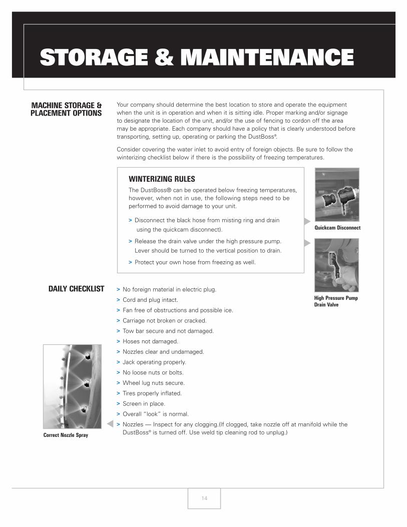
WINTERIZING RULES
The DustBoss® can be operated below freezing temperatures, however, when not in use, the following steps need to be performed to avoid damage to your unit.
> Disconnect the black hose from misting ring and drain
using the quickcam disconnect).
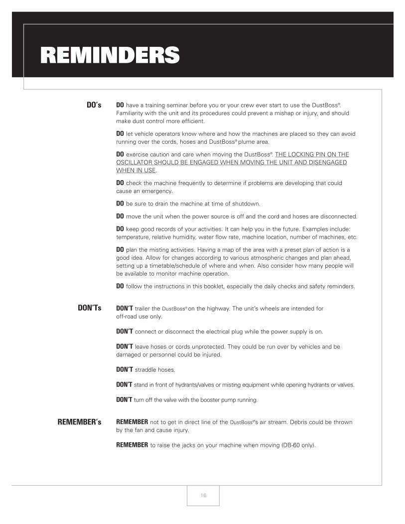
> Release the drain valve under the high pressure pump.
Lever should be turned to the vertical position to drain.
> Protect your own hose from freezing as well.
> No foreign material in electric plug.
> Cord and plug intact.
> Fan free of obstructions and possible ice.
> Carriage not broken or cracked.
> Tow bar secure and not damaged.
> Hoses not damaged.
> Nozzles clear and undamaged.
> Jack operating properly.
> No loose nuts or bolts.
> Wheel lug nuts secure.
> Tires properly inflated.
> Screen in place.
> Overall “look” is normal.
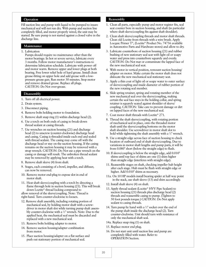
> Nozzles — Inspect for any clogging.(If clogged, take nozzle off at manifold while theDustBoss® is turned off. Use weld tip cleaning rod to unplug.)
▲
High Pressure Pump
Drain Valve
▲
Quickcam Disconnect
▲
Correct Nozzle Spray

15
QUARTERLYMAINTENANCE
CHECKLIST
The machine should be checked completely for unusual wear and/or damage three times per year.
SPECIFICS TO CHECK:
> Wheels, tires, lug nuts and bearings.
> Carriage for weld cracks or bends.
> Tow bar for wear, cracks or bends.
> Head mounting yoke for wear, cracks or bends.
> Manifold should be flushed clean.
> Nozzles checked for damage and wear.
> Fan housing and mounts inspected for cracks or wear.
> Fan visually inspected for structural cracks or nicks in blades.
> High pressure pump checked for damage and wear.
> Electrical cord inspected for nicks and abrasions or breakage.
> Plug checked for possible problems or breakage.
> All nuts, bolts and other fasteners checked for tightness.
> Protect the cord from sunlight (ultraviolet rays) to ensure its long life.
> Grease fan motor once every five years.
Recommended Spare Parts
> Nozzles.
> Extra Electrical Plug End and Boot.
> Extra Water Hose Gaskets for couplers.
▲▲
Unclogged Nozzle
Nozzles
▲
High Pressure Pump
16
REMINDERS
DO’s
DON’Ts
REMEMBER’s
DO have a training seminar before you or your crew ever start to use the DustBoss®.Familiarity with the unit and its procedures could prevent a mishap or injury, and shouldmake dust control more efficient.
DO let vehicle operators know where and how the machines are placed so they can avoidrunning over the cords, hoses and DustBoss® plume area.
DO exercise caution and care when moving the DustBoss®. THE LOCKING PIN ON THEOSCILLATOR SHOULD BE ENGAGED WHEN MOVING THE UNIT AND DISENGAGEDWHEN IN USE.
DO check the machine frequently to determine if problems are developing that couldcause an emergency.
DO be sure to drain the machine at time of shutdown.
DO move the unit when the power source is off and the cord and hoses are disconnected.
DO keep good records of your activities. It can help you in the future. Examples include:temperature, relative humidity, water flow rate, machine location, number of machines, etc.
DO plan the misting activities. Having a map of the area with a preset plan of action is agood idea. Allow for changes according to various atmospheric changes and plan ahead, setting up a timetable/schedule of where and when. Also consider how many people will be available to monitor machine operation.
DO follow the instructions in this booklet, especially the daily checks and safety reminders.
DON’T trailer the DustBoss® on the highway. The unit’s wheels are intended for off-road use only.
DON’T connect or disconnect the electrical plug while the power supply is on.
DON’T leave hoses or cords unprotected. They could be run over by vehicles and bedamaged or personnel could be injured.
DON’T straddle hoses.
DON’T stand in front of hydrants/valves or misting equipment while opening hydrants or valves.
DON’T turn off the valve with the booster pump running.
REMEMBER not to get in direct line of the DustBoss®’s air stream. Debris could be thrownby the fan and cause injury.
REMEMBER to raise the jacks on your machine when moving (DB-60 only).

ADDITIONAL RESOURCES
17
APPENDIX OF FIGURES ........................................................................................................................................................................................17
OPTIONAL BOOSTER PUMP INFORMATION ............................................................................................................................................18–23
> Installation, Operation, and Maintenance Instructions ........................................................................................................18–19
> Pump Specifications ..............................................................................................................................................................................20–21
> Repair Parts ......................................................................................................................................................................................................22
> Parts Specifications ......................................................................................................................................................................................23
DUSTBOSS� PARTS LIST ................................................................................................................................................................................24–28
> Fan Assembly ..................................................................................................................................................................................................24
> Spray Manifold ................................................................................................................................................................................................24
> DB-60 Galvanized Carriage Assembly ................................................................................................................................................24
> Wheel Assembly ............................................................................................................................................................................................25
> Enclosure Assembly ....................................................................................................................................................................................25
> Carriage Oscillator Assembly ..................................................................................................................................................................26
> DB-30 Carriage Assembly ..........................................................................................................................................................................26
> Universal Mount Assembly ......................................................................................................................................................................27
> Power Cord........................................................................................................................................................................................................27
> Selector Switch ..............................................................................................................................................................................................27
> Pilot Light Assembly ....................................................................................................................................................................................27
> Start/Stop Button Assembly ....................................................................................................................................................................28
> LED Lighted Selector Switch ..................................................................................................................................................................28

18
APPENDIX OF FIGURES
18
FIG.1Unpacking of DB-30
FIGS.2–10Unpacking & Assembly of DB-60

19
Installation,Operation andMaintenanceInstructions
Model45HB-70HBMulti-Stage Centrifugal Booster Pump
IM023R02
General InformationModels 45HB and 70HB are multi-stage, high-pressure,general-purpose centrifugal booster pumps, using enclosedimpellers. Applicable for clear, non-hazardous liquids ingeneral industrial services up to 180°F (82°C). Particularlysuited for high-pressure booster services.All models are close-coupled to electric motors containingprelubricated bearings designed for continuous service.Threaded shaft extension is protected by a stainless steel sleeve/coupling combination.All models are equipped with single, unbalanced mechanicalshaft seals.Units are shipped completely assembled and ready forinstallation.
Important1. Inspect unit for shipping damage.2. Read all instructions carefully.3. ALWAYS disconnect all electrical power when handling
pump, motor, or controls.4. Do not run unit dry or against a closed discharge. This
will result in damage to mechanical seal and pump.5. Never pump hazardous liquids or solvents.6. Maximum liquid temperature: 180°F (82°C).7. Maximum inlet pressure: 100 PSI.
InstallationLocation: Locate pump as near the liquid source as practical.Allow adequate room for servicing and ventilation. Protect theunit from cold weather freezing and water damage due to rainor flooding. Pump may be mounted horizontal; or verticalwith motor on top provided a drip-shield is used for motorprotection.
Foundation: Foundation surface must be flat so there is nodistortion and/or strain developed when tightening thefoundation bolts. CAUTION: Bolting and/or piping must notput strain on liquid end. The pumps are quiet and smoothrunning, but rubber mounting is recommended on foundationssusceptible to sound effect.Alignment: No filed alignment is necessary as pumps areclose-coupled.Piping: Suction pipe must be at least equal in size to suctionconnection of pump and provide positive suction head (intakepressure) to the pump. Avoid using the pump for applicationsrequiring suction lift. Never use a gate valve in the suction lineto throttle the pump. CAUTION: Piping must not put strainon the liquid end.Wiring: Electrical power supply must be a separatebranch circuit equipped with proper starters, fuses or circuitbreakers, wire size, etc., conforming to National ElectricalCode plus local codes. Power supply voltage, phase andcontrols must match motor nameplate requirements. Lowvoltage and phase-loss (3 phase) protection is recommended.Motors: Single-phase 3 HP motors are dual voltage 115/230volts, 60 Hz, A.C. Single-phase 5 HP motors are 230 volts, 60Hz, A.C. All other motors are three-phase, dual voltage 230/460 volts, 60 Hz, A.C. The higher voltages are recommendedwhere available.Rotation: Three-phase rotation must be checked at installationmy momentarily energizing the completely filled pump andobserving the rotation. Rotation is clockwise looking into themotor shaft, end-bell side (remove protective cap to observeshaft). Rotation must correspond to rotation arrow. Rotationof three-phase units can be reversed by interchanging any two(2) electrical power leads. CAUTION: Do Not run in reverserotation or damage will result.
2020
OperationFill suction line and pump with liquid to be pumped to insuremechanical seal will not run dry. With pump and suction linecompletely filled, and motor properly wired, the unit may bestarted. Be sure pump is not started against a closed valve in thedischarge line.
Maintenance1. Lubrication
Pumps should require no maintenance other than themotor bearings: In hot or severe service, lubricate every3 months. Follow motor manufacturer’s instructions todetermine lubrication schedule. Lubricate with power offand motor warm. Remove upper and lower plugs at bothbearing. Free lower relief hole of hard grease. Install cleangrease-fitting on upper hole and add grease with a low-pressure grease gun. Run motor 30 minutes. Stop motorand remove drained grease. Replace all plugs.CAUTION: Do Not over-grease.
Disassembly1. Turn off all electrical power.2. Drain system.3. Disconnect piping.4. Remove bolts holding motor to foundation.5. Remove shaft snap ring (1) within discharge head (2).6. Use a torch on both ends of casing to break-down
thread sealant at casing threads.7. Use wrenches on suction housing (21) and discharge
head (2) to unscrew (counter-clockwise) discharge headand casing. Casing is threaded inside each end and sealedwith thread sealant. The casing may come off with thedischarge head or stay on the suction housing. If the casingremains on the suction housing it may be removed with astrap wrench. CAUTION: Do Not use a pipe wrench on thecasing or damage will result. The unbroken thread sealantmay be removed by applying heat with a torch.
8. Remove shaft sleeve (4) from shaft.9. Stages, each consisting of a bowl, impeller, and diffuser,
can now be removed.10. Remove motor end-plug to expose slot in end of
motor shaft.11. Heat shaft sleeve/coupling with a torch by directing a
flame through hole in suction housing (21). This will breakdown Loctite® thread locking compound to
allow removal of the sleeve/coupling. Note: Thread isright-hand. Turn counter-clockwise to loosen.12. Remove shaft assembly, including rotating portion of
mechanical seal, by holding motor shaft with a screw-driver in motor shaft slot while turning pump shaft assem-bly counter-clockwise with a 1⁄2" wrench. Note: Due to theapplied heat, the mechanical seal must be discarded andreplaced with a new mechanical seal.
13. Remove bolts holding adapter to motor.14. Remove suction housing/adapter combination
from motor.15. Place suction housing/adapter on a flat surface and
push out stationary portion of mechanical seal.
Reassembly1. Clean all parts, especially pump and motor register fits, seal
seat counter bore in suction housing, and shaft (in particularwhere shaft sleeve/coupling fits against shaft shoulder).
2. Clean shaft sleeve/coupling threads and motor shaft threads.Clean old Loctite from threads with a wire brush. ApplyLocquic Primer T®, (Loctite® Product No. 74756 availablein Automotive Parts and Hardware stores) and allow to dry.
3. Lubricate counterbore of suction housing (21) and rubberbushing of new stationary seal seat with light oil or soapywater and press into counterbore squarely and evenly.CAUTION: Do Not mar or contaminate the lapped face ofthe new mechanical seal seat.
4. With motor in vertical position, remount suction housing/adapter on motor. Make certain the motor shaft does notdislocate the new mechanical seal stationary seat.
5. Apply a thin coat of light oil or soapy water to outer surfaceof sleeve/coupling and inside diameter of rubber portion ofthe new rotating seal member.
6. Slide spring retainer, spring and rotating member of thenew mechanical seal over the sleeve/coupling, makingcertain the seal face stays in the holding collar, and springretainer is squarely seated against shoulder of sleeve/coupling. CAUTION: Take care to prevent damage or dirton lapped faces of the new mechanical seal.
7. Coat motor shaft threads with Loctite® 271.8. Thread the shaft sleeve/coupling, with rotating portion
of mechanical seal in place, onto the threaded motorshaft until the sleeve/coupling bottoms on the motorshaft shoulder. Use screwdriver in motor shaft slot tohold while tightening the shaft assembly with a 1⁄2" wrench.
9. Use a straight edge across face of suction housing to checklocation of outboard end of shaft sleeve/coupling. Due tovariations in motor shaft lengths and pump parts, it will befrom 0.080" short (below the straight edge) to flush.
10. If sleeve/coupling is below the straight edge, add 0.010"shims until top face of shims are one (1) shim higherthan straight edge (interferes with straight edge).
11. Reassemble stages on shaft, checking impeller hub heightafter each stage. Hub must be flush with straight edge orhigher. Add 0.010" shims as necessary.
11a. On 10 HP models install bearing spider at half way pointin the stack, use shaft sleeve (13) and shim accordingly.
12. Install shaft sleeve (4) on shaft.13. Apply thread sealant (Loctite® HVV Pipe Sealant) to
suction housing (21) threads plus discharge head (2)threads and reassemble casing to pump. (Tighten to50 foot pounds torque.) CAUTION: Do Not applysealant to casing threads.
14. Turn pump by hand with a 1⁄2" socket over the end ofthe pump shaft inside the discharge head (2). Turncounter-clockwise. Unit should turn with resistance ofonly the mechanical shaft seal.
14a. Replace snap ring (1) on shaft.15. Replace motor end plug.16. Do not start unit until suction line and pump are
completely filled with water. Refer toOPERATION Section.

21
High PressureCentrifugalBooster Pump
45HB, 70HBMODEL
APPLICATIONS
Wide variety of industrial,commercial and agriculturaluses, especially:• High rise buildings• Multiple dwelling buildings• Reverse osmosis systems• High pressure cleaning• Spraying systems• Booster service
SPECIFICATIONS
Pump• Capacities: to 100 GPM• Heads: to 760 feet.• Pipe connections:
Suction 2" NPTDischarge 2" NPT.
• Temperature: 160ºF (71ºC)maximum.
• Inlet pressure: 100 PSImaximum.
• Rotation: right hand, i.e.,clockwise when viewedfrom motor end.
Motor• Open drip-proof or TEFC
enclosure60 Hz, 3500 RPM.Threaded shaft extension.
• Single phase:3 HP 115/208–230 V5 HP 208–230 V71⁄2 HP 208–230 V.
• Three phase:3–10 HP 208–230/460 V.
FEATURES
■ Multi-Stage Design: Thisconfiguration provides asteady, quiet and vibration-free operation for years oftrouble-free service.■ Impellers and Diffusers:Glass filled thermoplastic.Precision molded for highefficiencies.■ Bowls: Constructed with300 series stainless steel.Rabbet lock for positivealignment – no gasketsrequired.■ Mechanical Seal: Carbon/ceramic faces. BUNA elas-tomers 300 series stainlesssteel metal parts.■ Motor: Close-coupleddesign. Ball bearings carry allradial/axial thrust loads.Designed for continuousoperation. All ratings arewithin working limits of themotor.
© 2004 Goulds PumpsEffective June, 2004 www.goulds.comB45-70HB
Goulds Pumps is ISO 9001 Registered.
WARNING:This is a boosterpump. It has no lift capabil-ity. DONOT RUN DRY. DO NOTDEADHEAD.
Goulds Pumps and the ITT Engineered Blocks Symbol areregistered trademarks and tradenames of ITT Industries.

22
PRINTED IN U.S.A. SPECIFICATIONS ARE SUBJECT TO CHANGE WITHOUT NOTICE.
SUCTION
▼
1185763
DISCHARGE
▼
2141098
COMPONENTS MODELS
Order No. HP No. of Phase Enclosure Frame W.E.L.Wt.Stages (lbs.)
45HB13012 3 3 1 ODP 182 111⁄2 8845HB23012 3 2 1 TEFC 184 103⁄8 10145HB13035 3 3 3 ODP 145 111⁄2 5945HB23035 3 2 3 TEFC 182 103⁄8 8345HB15013 5 5 1 ODP 184 137⁄8 10045HB25013 5 4 1 TEFC 213 123⁄4 14745HB15035 5 5 3 ODP 182 137⁄8 8045HB25035 5 4 3 TEFC 184 123⁄4 9945HB17513 71⁄2 7 1 ODP 213 161⁄4 16945HB17535 71⁄2 7 3 ODP 184 161⁄4 10345HB27535 71⁄2 6 3 TEFC 213 151⁄8 15045HB11135 10 10 3 ODP 213 211⁄2 15545HB21135 10 8 3 TEFC 215 171⁄2 19070HB13012 3 2 1 ODP 182 103⁄8 8670HB23012 3 2 1 TEFC 184 103⁄8 9970HB13035 3 2 3 ODP 145 103⁄8 5770HB23035 3 2 3 TEFC 182 103⁄8 8170HB15013 5 4 1 ODP 184 123⁄4 9870HB25013 5 3 1 TEFC 213 111⁄2 14570HB15035 5 4 3 ODP 182 123⁄4 7870HB25035 5 3 3 TEFC 184 111⁄2 9770HB17513 71⁄2 6 1 ODP 213 151⁄8 17070HB17535 71⁄2 6 3 ODP 184 151⁄8 10170HB27535 71⁄2 5 3 TEFC 213 137⁄8 14870HB11135 10 9 3 ODP 213 201⁄4 15370HB21135 10 7 3 TEFC 215 171⁄2 188
Item No. Description Material
1 Hex shaft and coupling 300 series stainless steel
2 Suction housing Brass (ASTM B584)
3 Discharge head Brass (ASTM B584)
4 Shaft sleeve 300 series stainless steel
5 Bowl 300 series stainless steel
6 Diffuser Glass-filled thermoplastic
7 Impeller Glass-filled thermoplastic
8 Marine bearing BUNA
9 Casing 300 series stainless steel
10 Intermediate bearing spider Brass (ASTM B584)
Carbon/ceramic faces, BUNA11 Mechanical seal elastomers, 300 series stainless steel
metal parts.
OPTIONAL SUPPORT LEG – dimensions (in inches)
Model Frame A B CAM200 182/184 41⁄8 53⁄8 41⁄2AM201 213/215 41⁄8 53⁄8 51⁄4
NOTE: Support leg is not required for 145 frame motors.
DIMENSIONS – determined by motor (in inches)
145 61⁄2 51⁄4 515⁄16 47⁄8 6 31⁄2 23⁄4 2 5⁄3211⁄32 65⁄8
182⁄184 81⁄2 6 61⁄2 53⁄4 99⁄16 41⁄2 33⁄4 21⁄4 5⁄3213⁄32 81⁄2
213⁄215 91⁄2 73⁄8 8 71⁄4 97⁄16 51⁄4 41⁄4 23⁄4 7⁄3213⁄32 103⁄16
Frame A AB B BG C D E F G H O
(All dimensions are in inches. Do not use for construction purposes.)
Optional Support Leg
B
C
A
53∨8" Dia.
25∨8"BG C Max.
O Max.
4-H Dia. HolesB
F F
W.E.L.2" NPT Suction
DG
E EA
ABApprox.
2" NPTDisch.
31∨8"
High PressureCentrifugalBooster Pump
45HB, 70HBMODEL

23
0 10 20 30 40 U.S. GPM0
100
200
300
400
FEET
TOTA
L D
YNA
MIC
HEA
D
0
50
150
200
METERS
CAPACITY
MODEL 45HBSIZE 3–10 HP ODPRPM 3500IMP. B10761SERVICE FACTOR 1.15
50 60 70
800
0 155 10 m3/h
500
600
700
100
45HB10 10 STG
45HB75 7 STG
45HB50 5 STG
45HB30 3 STG
0
50
7060
40302010
EFF .
%
BASED ON ZERO INLET PRESSURE
MODEL 45HBSIZE 3–10 HP TEFCRPM 3500IMP. B10761SERVICE FACTOR 1.0
0 10 20 30 40 U.S. GPM0
100
200
300
400
FEET
TOTA
L D
YNA
MIC
HEA
D
0
50
150
200
METERS
CAPACITY
50 60 70
800
0 155 10 m3/h
500
600
700
100
BASED ON ZERO INLET PRESSURE
0
50
7060
40302010
EFF .
%
45HB10 8 STG
45HB75 6 STG
45HB50 4 STG
45HB30 2 STG
© 1999 Goulds PumpsEffective March, 1999C45-70 HB
Goulds Pumps is ISO 9001 Registered.
Close-CoupledMulti-Stage Pumps
45-70HBMODEL

24
25
DUSTBOSS� PARTS LIST
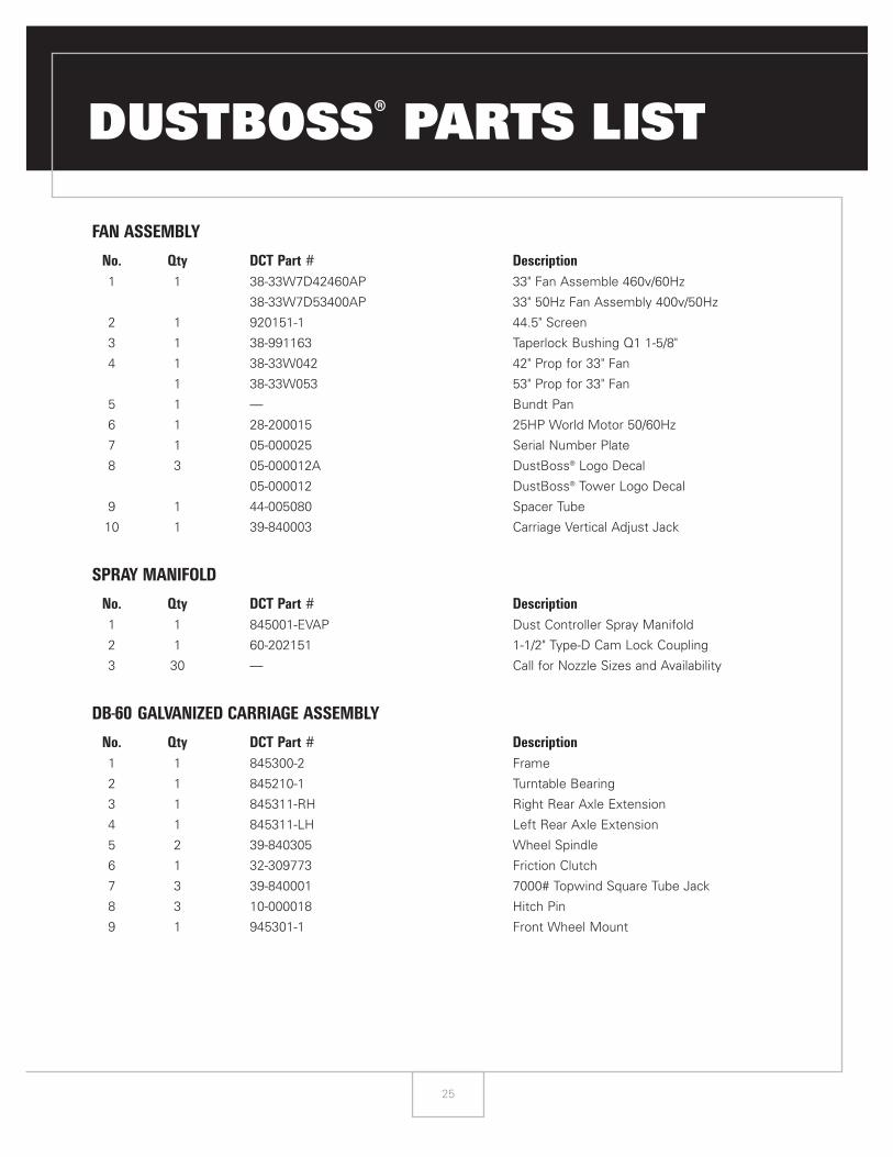
FAN ASSEMBLY
No. Qty DCT Part # Description
1 1 38-33W7D42460AP 33" Fan Assemble 460v/60Hz
38-33W7D53400AP 33" 50Hz Fan Assembly 400v/50Hz
2 1 920151-1 44.5" Screen
3 1 38-991163 Taperlock Bushing Q1 1-5/8"
4 1 38-33W042 42" Prop for 33" Fan
1 38-33W053 53" Prop for 33" Fan
5 1 — Bundt Pan
6 1 28-200015 25HP World Motor 50/60Hz
7 1 05-000025 Serial Number Plate
8 3 05-000012A DustBoss® Logo Decal
05-000012 DustBoss® Tower Logo Decal
9 1 44-005080 Spacer Tube
10 1 39-840003 Carriage Vertical Adjust Jack
SPRAY MANIFOLD
No. Qty DCT Part # Description
1 1 845001-EVAP Dust Controller Spray Manifold
2 1 60-202151 1-1/2" Type-D Cam Lock Coupling
3 30 — Call for Nozzle Sizes and Availability
DB-60 GALVANIZED CARRIAGE ASSEMBLY
No. Qty DCT Part # Description
1 1 845300-2 Frame
2 1 845210-1 Turntable Bearing
3 1 845311-RH Right Rear Axle Extension
4 1 845311-LH Left Rear Axle Extension
5 2 39-840305 Wheel Spindle
6 1 32-309773 Friction Clutch
7 3 39-840001 7000# Topwind Square Tube Jack
8 3 10-000018 Hitch Pin
9 1 945301-1 Front Wheel Mount

26
WHEEL ASSEMBLY
No. Qty DCT Part # Description
1 1 720115-1 Tow Bar
2 1 720116-1 Single Wheel Frame
720116-1A Single Wheel Frame with Axle & Hub
3 1 10-000013 Hitch Pin with Lynch Pin
4 3 39-000013 22 x 12-8 Tire and Wheel
5 2 320533-1 4" Bronze Bushing
6 3 39-000011 5-Bolt Hub Cast Iron
7 1 39-840305 Wheel Spindle
8 1 33-000007 Tow Bar Chain Assembly
1 FW-3 Front Wheel Assembly without Tow Bar
(includes items 2, 4, 5, 6, 7 & 8)
ENCLOSURE ASSEMBLY
No. Qty/Length DCT Part # Description
1 1 845200-1 Galvanized Enclosure
2 2 845201-1 Galvanized Lifting Bracket
3 1 845214-1 24ck & 45ck Compressor Bracket
4 1 845202-3A Anodized Travel Lock
845202-2 Travel Lock Pin
5 1 840208-1 240v Light Bracket
6 1 840203-2 Panel Bracket & Cord Rack
7 1 840203-1 Panel Bracket
8 3 845204-1 Galvanized Lifting Extension
9 2 10-000017 3/4" x 4-3/4" Hitch Pin with Lynch
10 1 840207-2 12" Strobe Light Nipple
11 1 21-840010 Strobe Light 120v
21-840011 Strobe Light 240v
12 1 21-000001 Metal Halide Fixture 240v
12A 1 21-000002 Replacement Bulb
13 1 39-000088 Rubber Light Housing without Lamp
14 1 21-000008 Floodlight 120v/150w
15 1 845220-2 Compressor Cover
16 6.25" 40-016012 1" dia. x .120 w x 3 c" Long Pivot Tube
17 1 06-002010 Level Gauge
18 1 21-840100 Halogen Flood Light 50w/12v
(on 2002 & newer)
19 1 840207-3 Spot Light Bracket

27
CARRIAGE OSCILLATOR ASSEMBLY
No. Qty DCT Part # Description
1 1 32-309773 Friction Clutch
1A 1 32-100814 Lock for Tension Nut
1B 2 32-325145 Friction Plates (comes as a set)
1C 1 32-308104 Guide Bushing
2 1 840211-2Z Oscillator Cam Hub – Zinc Plated
3 1 32-000100 Speed Reducer
4 1 400163-2 Oscillator Connecting Tube
5 2 39-000084 Rod End Oscillator Link
6 1 840235-3Z Clutch Plate – Zinc Plated
DB-30 CARRIAGE ASSEMBLY
No. Qty/Length DCT Part # Description
1 1 720101-1 PoleCat Chassis Weldment
2 1 720116-1 Single Wheel Frame Assembly
3 3 320533-1 4" Bronze Bushing
4 2 39-000046M Plastic Cap
5 3 39-000011 5-Bolt Hub – Cast Iron
3 — Cotter Pin
3 — Bearing Washer
3 — Hub Cap
6 — Bearings
15 — 1/2" – 20 Wheel Nuts
3 — Bearing Seals
3 — Spindle Nuts
6 3 39-000013 Wheel & Tire 22" x 12" x 8"
7 1 720101-1-BRKT Compressor Support Bracket
8 3 39-840305 Wheel Spindle 2-Bolt
9 1 400123-1 Yoke – Carriage Mount
10 1 720106-1 Universal Mount Assembly
11 1 720115-1 Tow Bar Assembly
12 1 10-000013 5/8" x 6-1/2" Hitch Pin with Lynch Pin
13 1 39-000029 Pintle Hook
14 2 39-000044 Jack Assembly
15 1 320103-5 Clamp Nut Assembly
16 1 39-840003 Carriage Vertical Adjust Jack
17 3.5" 44-005008 1/2" Sch 80 SS Pipe
18 6.25" 40-016012 1" dia. x .120 w x 3 c" Long Pivot Tube

28
UNIVERSAL MOUNT ASSEMBLY
No. Qty DCT Part # Description
1 1 720106-1 Universal Mount – Painted
2 1 320533-1 4" Bronze Bushing
3 1 320103-5 Clamp Nut Assembly
POWER CORD
No. Qty DCT Part # Description
1 1 25-0100009 8/4 Cord
(150' Carriage & 40' Tower is standard)
2 1 24-000022 Male 5w 60 Amp Pin & Sleeve Plug
1 24-000026 Male 7w 60 Amp Pin & Sleeve Plug 480v
1 — Other 60 Amp Plug Options are Available
3 1 — Cord Grip
4 1 — 1" Conduit Locknut
5 1 — 8/4 Cord Strain Relief
SELECTOR SWITCH
No. Qty DCT Part # Description
1 1 20-101048 Square D Selector Switch
2 1 — Legend Plate (Specify Engraving)
3 1 — Locknut (Included with #1)
4 1 20-101001 Mounting Collar
5 1 20-101000 N/O Contact Block
20-101004 N/O Contact Block with Mounting Collar
PILOT LIGHT ASSEMBLY
No. Qty DCT Part # Description
1 1 — Pilot Lens Only
(Specify Year for Current Lens)
2 1 **
3 1 **
4 1 **
5 1 20-101001 Mounting Collar
6 1 20-101035 White LED 120v Light Modules
** Available Only as Complete Pilot Light Part# 20-101030 – White or 20-101031 – Red.

29
START/STOP BUTTON ASSEMBLY
No. Qty DCT Part # Description
1 1 20-101096 Silicone Boot
2 1 20-101097 Combination Start/Stop Push Button
3 1 — (Included with #2)
4, 5, 6 1 20-101005 Contact Block with Collar N/O & N/C
LED LIGHTED SELECTOR SWITCH
No. Qty DCT Part # Description
1 1 20-101049 Red Illuminated Selector Switch
2 1 — Legend Plate (Specify Engraving)
3 1 — Locknut (Included with #1)
4 1 20-101001 Mounting Collar
5 1 20-101035 White LED 120v Light
6 1 20-101000 N/O Contact Block

30
WARRANTY
A.THE WARRANTY PERIOD SHALL BE TWELVE MONTHS FROM THE DATE OF PURCHASE FOR ALL MODELS.
B.DURING THE PERIOD OF WARRANTY, DUST CONTROL TECHNOLOGY® GUARANTEESTO THE ORIGINAL PURCHASER OF EACH DUST CONTROL MACHINE:
Any part adjudged by the manufacturer defective by reason of faulty workmanship or material shall be replaced free of charge upon return of broken part.
C.THE WARRANTY SHALL BE EFFECTIVE IF PURCHASER:
Gives notice to an authorized distributor of any and all apparent defects within ten (10) days after discovery and immediately makes machine available for inspection to the distributor or his authorized representative.
D.WARRANTY SHALL NOT EXTEND TO:
1. Machines used for renting or leasing beyond the original owner.
2. Machines subjected to abnormal strain, neglect, abuse, improperly stored, or altered from factory standard.
3. Machines whose trademark, name, or identification number has been changed or removed.
4. Failures of, or failures caused by parts or accessories not manufactured by Dust Control Technology®.
E.WHERE PERMITTED BY LAW:
1. COMPANY'S LIABILITY SHALL BE LIMITED TO THAT SET FORTH IN THIS WARRANTY, AND COMPANY SHALL NOT BE LIABLE FOR INCIDENTAL OR CONSEQUENTIAL DAMAGES, INCLUDING INJURY TO PERSON OR PROPERTY.
2. COMPANY MAKES NO OTHER WARRANTY OF ANY KIND, EXPRESSED ORIMPLIED; AND ALL IMPLIED WARRANTIES OF MERCHANTABILITY AND FITNESSFOR A PARTICULAR PURPOSE WHICH EXCEED THE OBLIGATION STATED IN THISWARRANTY ARE HEREBY DISCLAIMED BY COMPANY AND EXCLUDED FROMTHIS WARRANTY.
As set forth herein, the term “machine” shall refer to misting machines as manufactured by Dust Control
Technology� and sold by authorized distributors. Claims for warranty shall be submitted by the authorized
distributor who performs or authorizes the repairs.