Durham E-Theses Petrology and geochemistry of gabbroic and ... · Petrology and geochemistry of...
218
• • •
Transcript of Durham E-Theses Petrology and geochemistry of gabbroic and ... · Petrology and geochemistry of...
Durham E-Theses
Petrology and geochemistry of gabbroic and ultrabasic
rocks from eastern Rhum
Faithfull, John William
How to cite:
Faithfull, John William (1986) Petrology and geochemistry of gabbroic and ultrabasic rocks from eastern
Rhum, Durham theses, Durham University. Available at Durham E-Theses Online:http://etheses.dur.ac.uk/6867/
Use policy
The full-text may be used and/or reproduced, and given to third parties in any format or medium, without prior permission orcharge, for personal research or study, educational, or not-for-pro�t purposes provided that:
• a full bibliographic reference is made to the original source
• a link is made to the metadata record in Durham E-Theses
• the full-text is not changed in any way
The full-text must not be sold in any format or medium without the formal permission of the copyright holders.
Please consult the full Durham E-Theses policy for further details.

Academic Support O�ce, Durham University, University O�ce, Old Elvet, Durham DH1 3HPe-mail: [email protected] Tel: +44 0191 334 6107
http://etheses.dur.ac.uk
2

PETROLOGY AND GEOCHEMISTRY OF GABBROIC AND
ULTRABASIC ROCKS FROM EASTERN RHUM
John William Faithfull
B.Sc (Dunelm)
Geology Department
Durham University
•
The copyright of this thesis rests with the author.
No quotation from it should be published without
his prior written consent and information derived
from it should be acknowledged.
Thesis submitted for the degree of
Doctor of Philosophy
University of Durham
1986

r ~ • t ,
l. ./ :
• •· • I '"
"J •• I\
. f ~ I 1
, 1 t ; I 1 ' '"
. t

Abstract
This work is concerned with the lower part of the
Eastern Layered Series (LELS) of Rhum, and with the
marginal relationships of the ultrabasic complex in
eastern Rhum.
The Lower Eastern Layered Series comprises
approximately Units 1-5 of previous workers. Remapping
has revealed considerable along-strike lithological
variation in the units of the L.E.L.S. It is suggested,
on the basis of field and geochemical evidence, that two
layers formerly regarded as 'conformable intrusive
sheets of fine grained olivine gabbro', may be evolved
allivalite layers rather than later intrusions. Xenolith
suites in these layers and elsewhere, indicate a
component d~rived from the roof or walls of the magma
chamber. Cryptic variation is more extensive in the
L.E.L.S. than in other parts of Rhum: olivine forsterite
content varies from 85.6 to 70, and clinopyroxene
MgX100/(Mg+Fe) varies from 88 to 74. Post-cumulus
effects and sub-solidus re-equilibration have altered
the initial compositions of the mineral phases. The
migration of interstitial liquids has had a major effect
on mineral chemistry. Replacement of plagioclase-rich
rocks by peridotite is a significant process in parts of
the sequence. This is ascribed to disequilibrium between
migrating pore liquids and plagioclase. The data are
consistent with a model of repeated replenishment by
picritic magma, although the replenishing liquids may
have been slightly less magnesian than those
subsequently available during the formation of the upper
ELS.
Re-examination of the eastern margin of the
ultrabasic complex suggests that the ultrabasic rocks
formed more or less in situ, and that fragments of the
roof to the intrusion occur in places. Locally under
these roof fragments variolitic olivine-rich gabbros are
developed, which may represent the chilled margin to the
ultrabasic complex.
II

DECLARATION
The work described in this thesis is my own.
except where otherwise stated, and has not been
submitted for degree in this or any other university.
The copyright of this thesis rests with the
author. No quotation from it should be published without
his prior wr~tten consent, and information derived from
it should be acknowledged.
\\1

TABLE OF CONTENTS
Chapter 1 Introductory remarks
1.A Introduction
1.8 Rhum geology - general
1. 8. 1 Lewis ian rocks
1 .8.2 Torridonian rocks
1 .8.3 Mesozoic rocks
1 .8.4 Early Tertiary rocks
1 .C Previous work on the LELS
·1. 0 The present work
Chapter 2 Marginal Relationships
2.A Torridonian rocks
2.8 Morphology of the margin
2.C
2.0
2.E
Field relations
Petrography
2.0.1 Basic rocks
2.0.2 Intermediate rocks
2.0.3 Acid rocks
Conclusions
Chapter 3 The Layered Rocks
3.A Sub-division of the LELS
3.B Field relations
3.B.1 Unit
3.B.2 Unit 2
3
3
3
4
6
7
8
1 0
1 0
1 6
1 6
22
22
22
24
27
27
28
3.8.3 Unit 3 32
3.B.4 Unit 4 35
3.8.5 Unit 5 37
3.B.6 Gabbro plugs and sheets 41
3.C Petrography 4 1
3.C.1 Peridotites 4 1
3.C.2 Peridotite/allivalite
contacts 54
3.C.3 Allivalites 61
3.C.4 Gabbro plugs and sheets 72
3.0 Conclusions
Chapter 4 Bulk-rock chemistry
4.A The Marginal Suite
4.B Gabbro plugs and sheets
4.C The layered rocks
4.C. 1 Cluster analysis
74
76
84
86
86
4.D
4.C.2 CIPW norms
Conclusions
Chapter 5 Mineral Chemistry
5.A The layered rocks
5.A.1 Olivines
5.A.2 Clinopyroxenes
5.A.3 Olivine/clinopyroxene
relationships
5.A.4 Plagioclases
5.A.5 Orthopyroxenes
5.A.6 Sulphides
5.A.7 Kaersutites
5.A.8 Hydrous minerals in
allivalites
5.8 Some aspects of xenolith minaral
92
92
93
93
99
1 0 5
1 0 7
1 0 7
109
1 1 '1
1 1 3
chemistry 113
5.8.1 Pigeonite 113
5.8.2 Fassaite-bearing xenoliths 115
5.C Conclusions
Chapter 6 Cryptic Variation
6.A General
6.8 Discussion
6.C Variation in clinopyroxene
minor elements
6.C.1 Aluminium
6.C.2 Titanium
6.C.3 Chromium
6.D Conclusions
Chapter 7 Discussion and conclusions
7.A The formation of the LELS
7.A.1 Types of small-scale
1 1 8
1 2 0
1 2 2
1 3 2
132
1 3 2
1 3 2
1 3 4
1 3 5
layering 136
7.A.2 The origins of small-scale
layering 137
7.8 Parental magmas, contamination
7.C
7.0
and evolution.
Fingers and replacement
7.C.1 Discussion
Evolution of the ultrabasic
complex.
1 4 0
145
146
148
7.E Emplacement of the complex
BIBLIOGRAPHY
ACKNOWLEDGEMENTS
APPENDICES
1. XRF analyses of international
standards.
2. XRF analyses of Rhum samples
3 . Sample locations
4. Published articles arising from
this work.
VI
1 4 9
1 50
1 58
159
1 6 4
1 7 5
1 7 8

Fig. 1.1
Fig 2. 1
Fig 2.2
Fig 2.3
Fig 2.4
Fig 2.5
Fig 2.6
Fig 2.7
Fig 2.8
Fig 2.9
Fig 2.10
Fig 2.11
Fig 2.12
Fig 3. 1
Fig 3.2
Fig 3.3
Fig 3.4
Fig 3.5.
Fig3.6
Fig 3.7
FIGURES
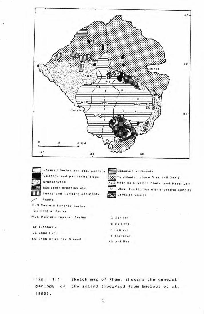
Sketch map of Rhum, showing the general
geology of the island. 2
Geol6gy of the LELS and adjacent rocks. 9
Partially melted Rubha na Raine Grit. 11
Basic dyke breaking up in partially
melted Bagh na h-Uamha shale.
Schematic diagram showing marginal
relationships in the Cnapan Breaca/
Allt Mhor na h-Uamha area.
Skeletal olivine crystals in variolitic
1 1
1 4
-te~tured picrite. 17
Skeletal olivine crystals in variolilic
gabbro.
Olivine gabbro (cumulate?).
Gabbro from Marginal Suite.
Analcime-rich mesostasis.
Clinopyroxene altering to secondary
gre~n fibrous amphibole and biotite.
Inverted tridymite crystals in melted
Rubha na Raine Grit.
Microgranite with clear quartz,
turbid alkali feldspar, biotite and
magnetite.
Revised map of tt-1e LELS, and
stratigraphic section.
Finger structures cutting low-angle
1 7
1 9
1 9
20
20
2 1
21
25
slUmp folds in unit 2 allivalite. 29
Lipper part of unit 2 allivalite heavily
disrupted by finger structures. 29
.. Inverted must1room"' ~.tyle load
structures in unit 2 allivalite. 31
Slumped and mixed peridotite/allivalite
in the lower part of unit 3 allivalite. 31
Fine-grained plagioclase rich layer
in the lower part of unit 3 allivalite. 33
Deformed "'xenolith"' of troctolitic
allivalite in clinopyroxene-rich
VII
Fig 3.8
Fig 3.9
Fig 3.10
Fig 3~ 11
Fig 3.12
Fig 3 . 1 3 .
Fig 3 . 1 4
Fig 3 . 1 5
Fig 3. 1 6
Fig 3. 1 7
Fig 3 . 1 8
Fig 3.19
Fig 3.20
Fig 3.21
Fig 3.22
Fig 3.23
Fig 3.24
Fig 3.25
Fig 3.26
Fig 3.27
Fig 3.28
Fig 3.29
Fig 3.30
Fig 3 . 3 1
Fig 3.32
allivalite of unit 4.
Gradational contact between unit 5
peridotite and allivalite.
Layering in unit 5 allivalite.
Allivalite layer occurring in the
lower part of unit 6 peridotite.
Disappearance of unit 6 allivalite
through fingering.
View looking down on fingers in
unit 6.
Feldspathic peridotite with low
density of olivine crystals.
Peridotite from unit 5.
Peridotite from unit 5.
Peridotite from unit 5.
Peridotite from unit 2.
33
38
38
39
39
4 2
42
44
4 4
46
4 6
Intersecting laminations in peridotite 47
Preferential concentration of
chrome-spinel crystals on the upper
surfaces of olivines. 47
Hydrous minerals in peridotite from
unit 2. 50
Interst{tial orthopyroxene crystal
being made over to hornblende etc. 50
Pyroxene-syenite vein from unit 1
peridotite.
Teschenitic ve1n from unit 2/3
peridotite.
C om p o s i t e s u 1 ph i d e b 1 e b from u n i t 1 .
Magnetite/sulphide intergrowth.
Chrome-spinel layer from the lower
52
52
53
53
part of unit 3. 55
Mixed peridotite/allivalite layer. 55
Deformed peridotite/allivalite contact 56
Finger sectioned at 90° to its ax1s. 56
Finger from unit 8 allivalite.
Gradational peridotite/allivalite
contact.
Gradational allivalite/peridotite
contact.
VIII
57
59
GO

Fig 3.33
Fig 3.34
Fig 3.35
Fig 3.36
Fig 3 . :3 7
Fig :3.:38
Fig 3 . 3 9
Fig 3.40
Fig 3 . 4 1
Fig 3.42
Fig 3.43
Fig 3.44
Fig 4 . 1 a
Fig 4.1b
Fig 4 . 2 a
Fig 4.2b
Fig 4.3
Allivalite from unit 5. 62
Contact be~ween coarse and fine
grained layers in unit 3 allivalite. 62
Clinozoisite-rich ""clot'' in allivalite 64
Small dispersed sulphide blebs.
Exsolution lamellae of pentlandite
in large pyrrhotite grain.
64
66
Composite sulphide bleb from unit 1. 66
Beerbachite xenolith from unit 5. 68
Beerbachite xenolith from unit 4 with
"clots" of calc-silicate minerals. 68
Outer margin of fassaite zone from a
calc-silicate clot. 71
Large (cumulus?) hypersthene crystal. 71
Inverted pigeonile oikocryst. 73
Gabbro xenolith from unit 5 allivalite 73
Ba vs Cr- plot for the Marginal Suite. 77
Ba vs K2
o plot for the Marginal Su~lJ.
MgO vs P2o
5 plot for the Marginal
Suite.
MgO vs Ti02
plot for the Marginal
Suite.
Trate-eiement compositions of various
77
79
79
Torridonian sediments and felsite. 81
Fig 4.4a,b Trace element compositions of the
Marginal Suite. 83
Fig 4 . 5
Fig 4. 6
Fig 4.7
Fig 4 . 8
Fig 4 . 9
Fig 4 . 1 0
Fig 5 . '1
Fig 5.2a
Fig 5.2b
Fig 5.3
MgO vs Zn plot for the Marginal Suite 85
Trace element compositions of gabbro
plugs and sheets.
MgO vs CaO plot for the LELS rocks.
MgO vs P2
o5
plot for the LELS rock~;.
Dendrogram for the LELS allivalites,
""sheetrocks"". and gabbro plugs and
85
87
87
sheets. 88
Normative compositions of LELS rocks. 91
Ol~vine Fo-NiO relationships for U1 94
Fo content vs MnO for U1 olivines. 97
Fo content vs CaO for U1 olivines. 97
Clinopyroxene compositions for LELS
rocks. 98
\')(
Fig 5.4a
Fig 5.4b
Fig 5.5
Fig 5.6
Fig 5.7
Fig 5.8
Fig 5.9
Fig 5.10
Fig 5.11
Fig 5.12
Fig 6.1.
Fig 6.2
Fig 6.3
Fig 6.5
MGN, vs Al per 6 oxygens for LELS
clinopyroxenes. 1 0 1
Al in tetrahedral sites vs MGN for
LELS clinopyroxenes. 1 0 1
MGN vs Ti per 6 oxygens for LELS
clinopyroxenes. 1 0 2
MGN vs Cr per 6 oxygens for LELS
clinopyroxenes. 1 0 2
MGN vs Na per 6 oxygens for LELS
clinopyroxenes. 1 0 4
Relationship between olivine Fa
content and Mgn of clinopyroxenes. 104
Relationship between olivine Fa
content andMgn of orthopyroxenes.
Compositions of epidotes from sample
UJA2.
Host-lamellae relationship in inverted
pigeonite.
Pyroxene compositions in the zone
surrounding a garnet/diopside clot.
Variation of olivine Fa content and
clinopyroxene Mgn with height.
Variati~n in LFo-LMgn with height.
Density variation with MgO content
of basic liquids.
Variation of clinopyroxene total Al
and Al(ivl contents with height.
Variation of clinopyroxene Ti and Cr
contents with height.
1 0 8
1 0 8
1 1 4
1 1 7
1 2 1
1 2 4
1 2 8
1 3 1
1 3 3

based on
ADDENDUM
An 1:10000 geological map of eastern Rhum,
the fieldwork of the present author. A.R.
Butcher, J.A. Volker, and J. McClurg is enclosed at the
back of this volume. It is based on an original prepared
by A.R. Butcher.
Electron microprobe analyses obtained during
the course of this work are deposited with the
Department of Geological Sciences, University of Durham.
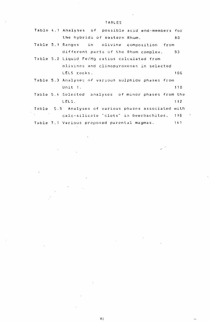
TABLES
Table 4.1 Analyses of possible acid end-members for
the hybrids of eastern Rhum. 80
Table 5.1 Ranges in olivine composition from
different parts of the Rhum complex. 93
Table 5.2 Liquid Fe/Mg ratios calculated from
olivines and clinopyroxenes in selected
LELS 1~ocks.
Table 5.3 Analyses of various sulphide phases from
1 0 6
Unit 1'.
Table 5.4 Selected
LELS.
analyses
1 1 0
of minor phases {rom the
1 1 2
Table 5.5 Analyses of various
calc-silicate "clots"
phases associated with
in beerbachites. 116
Table 7.1 Various proposed parental magmas. 1 4 1
X!

CHAPTER ONE
1 . A. INTRODUCTION
The island of Rhum is remarkable among the Tertiary
volcanic centres of western Scotland for the extensive
development of layered ultrabasic rocks. These rocks
outcrop principally in central and eastern Rhum; to the
west is an older Tertiary granophyre, while the northern
and extreme eastern parts of the island are made of
Precambrian clastic sediments.
The ultrabasic rocks have recently been divided
into three lithostratigraphic units: the Western and
Eastern Layered Series, and the Central Series (fig 1.1)
The Western Layered Series (WLS), first defined by
Wadsworth (1961) and modified by McClurg (1982), is
almost wholly comprised of crescumulate rocks. At its
base, on the western side of Harris Bay, these are
olivine-plagioclase crescumulates, while further up the
sequence olivine-rich rocks are dominant.
The Central Series (CS), defined by McClurg (1982)
and Volker (1983) has a transgressive contact with the
WLS and post-dates it. It forms a lobate mass, elongated
north-south, comprising a wide variety of ultrabasic
cumulates and intrusion breccias. Layering is only
locally well developed and is often highly deformed. The
CS also shows a transgressive relationship to the
Eastern Layered Series.
The Eastern layered Series (ELS) was first defined
by Brown (1956) although McClurg (1982) and Volker
(1983) were .the first to map its western boundaries. The
ELS is characterised by regular, large-scale rhythmic
layering, with alternating layers of olivine-
and olivine-plagioclase cumulates, the latter known
locally as allivalites (Harker, 1908).
This work is concerned with the lower parts of the
ELS, hereafter known as the LELS, and with the eastern
marginal relationships of the ultrabasic mass.
1 . B. RHUM GEOLOGY- GENERAL
In order that the LELS rocks can be sensibly
~· Layered Series and ass . gabbros
• .. Gabbros. and peridotite plugs
~ Granophyres
• Explos i on brecc i as et-c
IIIIIIJHIJJ. Lavas and Tert i ary sediments
" Faults /
ELS Eastern Layered Series
cs Central Series
WLS Western Layered Series
LF F l achanls
LL Long Loch
LG Loch Co Ire nan Grunnd
05
00
95
~Mesozo i c sed i ments
l•:•;O:JTorrldonlan above B na h-U Shale
J":.;-::;~.:::Jeagh na h-Uamha Shale and Basal Gr i t
0 Ml_sc . Torrldonlan within central complex
• Lewlslan Gneiss
A Ask l val
B Ba r keval
H Hall l val
T Trallaval
AN Ard Nev
1 • 1 Fig.
geology of
Sketch map of Rhum, showing the general
the island (modif ~~d from Emeleus et al,
1985).
2
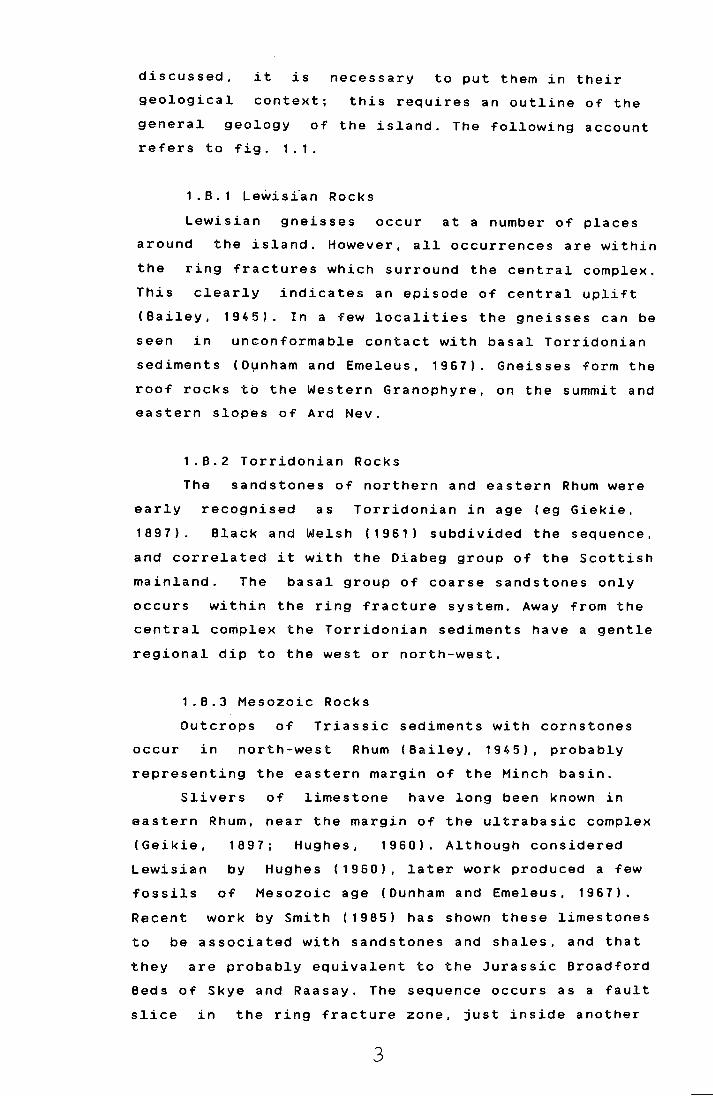
discussed, it is necessary to put them in their
geological context; this requires an outline of the
general geology of the island. The following account
refers to fig. 1.1.
1 .8.1 Le~isi~n Rocks
Lewisian gneisses occur at a number of places
around the island. However, all occurrences are within
the ring fractures which surround the central complex.
This clearly indicates an episode of central uplift
(Bailey, 1945). In a few localities the gneisses can be
seen in
sediments
unconformable contact with basal Torridonian
(D~nham and Emeleus, 1967). Gneisses form the
roof rocks to the Western Granophyre, on the summit and
eastern slop~s of Ard Nev.
1.8.2 Torridonian Rocks
The sandstones of northern and eastern Rhum were
early
189 7).
recognised as Torridonian in age (eg Giekie,
8latk and Welsh (1961) subdivided the sequence,
and correlated it with the Diabeg group of the Scottish
mainland. The basal group of coarse sandstones only
occurs within the ring fracture system. Away from the
central complex the Torridonian sediments have a gentle
regional dip to the west or north-west.
1.B.3 Mesozoic Rocks
Outcrops of Triassic sediments with cornstones
occur in north-west Rhum (Bailey, 1945), probably
representing the eastern margin of the Minch basin.
Slivers of limestone have long been known in
eastern Rhum, near the margin of the ultrabasic complex
(Geikie, 1897; Hughes, 1960). Although considered
Lewisian by Hughes (1960), later work produced a few
fossils of Mesozoic age (Dunham and Emeleus, 1967).
Recent work by Smith (1985) has shown these limestones
to be associated with sandstones and shales, and that
they are probably equivalent to the Jurassic Broadford
Beds of Skye and Raasay. The sequence occurs as a fault
slice in the ring fracture zone, just inside another
3
fault slice containing Lewisian gneiss. While the
distribution of gneiss provides evidence for central
uplift, the presence of these rocks, stratigraphically
higher than anything else seen in the pre-Tertiary of
Rhum, is clear evidence for central downfaulting
(Emeleus et al, 1985).
1.8.4 Early Tertiary Rocks
Basaltic dykes occur right through the period of
Tertiary activity on Rhum; these are not discussed here.
A thorough account of recent ideas on early Tertiary
activity can be found in Emeleus et al, (1985), on which
the following account is largely based.
(a)Explosion Breccias
The first major signs of Tertiary activity on Rhum
are seen in explosion breccias (but see section (d)).
These occur only within the ring fractures around the
central complex, although they are probably related to a
subsidence event along one of these faults, and it is
rather difficult to disentangle the effects of tectonic
and explosive brecciation. They are mostly made of
shattered basal Torridonian rocks, although gneiss and
gabbro are. also found. This explosive volcanism is
clearly a near-surface phenomenon.
(b)Felsites and Tuffisites
Intimately associated with the explosion breccias,
and cutting them, are felsite masses and tuffisite
dykes. At least some of the felsites are probably
ignimbrite.s formed subaerially (Williams, 1985).
(c)Granophyres
A large mass of granophyre occurs in western Rhum.
Its contacts with the Torridonian sediments to the north
are faulted. This is presumably a continuation of one of
the ring fractures seen in the easter part of the
complex, but correlation is difficult due to poor
exposure of the faults, later movement on the
north-south Long Loch fault, and the intrusion of the
ultrabasic complex across the line of the ring
fractures. Other small granophyres occur near the north
end of Long Loch, and at Papadil.
'· •'

Basalts occur in two distinct settings in Rhum. A
few flows of basalt, hawaiite and icelandite occur in
western Rhum, :infilling Tertiary river valleys cut into
the granophy~e and the Torridonian sediments.
Conglomerates: under these flows include clasts of
peridotite, allivalite and other rocks from the central
complex. Thes~ lavas are thus a late feature, following
erosion and unroofing of the central complex (Black,
1952; Emeleus., 1985).
Basalts: also occur with the Mesozoic sediments of
eastern Rhu~ (Emeleus and Forster, 1979; Smith, 1985).
They are hi~hly sheared and altered, with zeolites and
epidote in amygdales. Smith (1985) states that they are
in unfaulted, unconformable contact with the Jurassic
rocks. They •re therefore much older than the basalts of
western Rhum, and if the explosion breccias and felsites
really are surface products, they must pre-date them as
well, having been eroded off by the time the explosive
volcanism 9ccurred. They may be the only remnants of
pre-Central: Complex Tertiary plateau basalt activity
left on Rhum. Such activity might be expected, as most
of the oth~r Tertiary centres of western Scotland have
plateau ba;salts formed before the onset of central
activity.
(5) T~e Ultrabasic Complex
The u+trabasic rocks were first examined in detail
by Harker (1908). He regarded them as having been
produced by successive, more or less conformable
injections: of peridotite and allivalite magmas. Wager
and Brown :( 1951) recognised similiarities with the rocks
of Skaer~aard, and proposed a cumulate origin for the
layered iocks. Subsequent work by Brown (1956) and
Wadsworthi(1961) supported this idea. Both stressed the
role of 'periodic replenishment in the Rhum magma
chamber. · Rhum was used as one of the type examples in
the development of cumulate terminology (Wager, Brown
a n d Wad s w,o r t h , 1 9 6 0 ) .
Har~er (1908) regarded the ultrabasic rocks as a
laccolith, more or less sitting on top of a Palaeozoic
5

thrust. Bailey (1945) reinterpreted the thrust as a
ring fault. Brown (1956) agreed with Bailey that there
had been uplift along a ring fault, but that a second,
later inner ring fault had brought up the layered rocks,
in a semi-solid state, this later ring fault now being
filled by a gabbroic ring dyke. Dunham (1962,1964)
examined the marginal relationships around Meall Breac
and Cnapan Breaca and found intrusion breccias and
hybrid rocks developed between the marginal gabbro ring
dyke and the country rocks.
This "uplift-with-ring-dyke" model has recently
been questioned (Faithful!, 1985; Emeleus et al, 1985).
Many contacts between the ultrabasic rocks and the
country rocks are not steeply inclined; low-angle
contacts are found with the Western Granophyre on Ard
Nev and Ard Mheall, and with Torridonian and early
Tertiary rocks on Cnapan Breaca and Beinn nan Stac. It
has been suggested that some or all of these contacts
may be unfaulted igneous contacts (this work; Emeleus at
al 1985; R. Greenwood, pers comm 1985), implying that
what had previously been regarded as a later gabbro
intrusion may be, at least in part, the marginal facies
of the ultrabasic magma chamber.
Brown (1956) and Wadsworth (1961) could find little
or no cryptic variation in the Rhum cumulates; however
more recent work (Dunham and Wadsworth, 19 7 8) has
confirmed its presence on a rather limited scale, in
both the ELS and the WLS.
1 • c. PREVIOUS WORK ON THE LELS
Harker (1908) noted that the layered rocks low down
on the eastern slopes of Hallival and Askival differed
from those higher up. The lower rocks had less well
developed layering and lamination, and they were
mineralogically more complex, rarely showing the mono
or bi-minerallic modes of the upper rocks. Accordingly,
he mapped the lower part of the layered sequence as a
separate "eucrite" intrusion.
Brown (1956) noted the same differences, but
instead interpreted them in terms of interstitial liquid
6

retention ~n the lower rocks, in contrast to the upper
ELS where adcumulus growth had displaced the melt.
Since then, no systematic work has been carried out
on the LELS, although various studies on isolated topics
have been made. Such works will be referred to in the
text as and when appropriate.
1 . D. THE PRESENT WORK
The present work is based on fieldwork carried out during 1980, 1981 and 1982. Remapping of the LELS and
its margins was undertaken as existing maps CBrown,1956)
proved to be lacking in the necessary detail. Mapping
was carried out on aerial photographs and transferred to
the 1:10000 topographic map produced by Glasgow
University. During the course of this work it became
apparent that much of what had been mapped as intrusive
gabbro cutting the layered rocks, was itself layered and
shared many features of the LELS allivalites. In
addition the LELS proved to exhibit marked lithological
changes along strike. Studies of bulk-rock and mineral
geochemistry were undertaken to examine the extent of
cryptic variation in the cumulates, and to examine the
relationships between the various gabbros and the
layered rocks. In conjunction with other contemporary
workers on Rhum, considerable evidence has been built up
supporting an important role for post-cumulus processes
in shaping the chemistry and modal mineralogy of the
layered rocks now seen.
The margins of the complex were also re-examined.
The "Marginal Gabbro" ring-dyke of Brown (1956) is
reinterpreted as a complex zone of hybrids and gabbros,
which may represent the original margins to the
ultrabasic magma chamber. In a number of localities
fragments of the roof are preserved.
7
CHAPTER TWO
MARGINAL RELATIONSHIPS
The layered rocks of eastern Rhum are bounded
to the east by a zone of gabbros and hybrid rocks,
hereafter referred to as the Marginal Suite, largely
occupy~ng the line of a previously existing ring
fracture. The country rocks outside this zone are mainly
Torridonian sediments. These also occur locally within
the ring fracture, where they are extensively cut by
early Tertiary acid intrusive rocks and basaltic dykes.
This chapter deals with the igneous rocks of
the Marginal Suite, and the country rocks immediately
adjacent (fig 2.1).
2.A. TORRIDONIAN ROCKS
As mentioned above, the complex is bounded to the east
by a series of Torridonian sediments with a regional dip
of about 0 to 20 to the north-west. Thus as the
contact is followed to the east and south , the complex
abuts against successively lower members of the
sequence.
The Torridonian sediments of Rhum have been
divided (Black and Welsh; 1961) into 5 units, of which
only the lowest three occur in the area mapped. The
Basal Grit occurs only within the ring fractures, where
it forms the area around Cnapan Breaca, overlying the
layered rocks. At this locality the rocks are tightly
folded and very steeply dipping or vertical (Dunham,
1968). They comprise coarse gritty sandstone5with rare
shaly or silty intercalations. Further outcrops of this
sandy facies occur in the Allt nam Ba valley. Here they
are neither so tightly foldednor steeply dipping. Above
the basal grits which are about 100m thick, lies a thick
( 400m +) sequence of dominantly silty or shaly clastic
sediments known as the Bagh na h-Uamha shale. This is
found both within the ring fractures, where it is seen
to overlie the basal grit, and outside, where it is the
lowest exposed member of the Torridonian. Outside, and
8

Breaca
C Country rocks
p
Marginal gabbros,
diorites etc
Peridotite
Allivalite
:·{(A{::.} Fine grained Ia yer at ::::_:· .. .-:::_'.:·:· the top of Unit 4
'
Gabbro plugs and
sheets
'-'\ Ring fault
'- Dip of igneous layering
\ _Dip of sediments
Lines showing the
units as defined in the
Alii nam Ba
SO Om
SCALE
c
c
Fig 2. 1 Geology of the LELS and adjacent rocks.
9
18 H li
c
41

away from the ring faults the Torridonian rocks have a
gentle regional dip to the north-west, and hence along
most of the eastern contact of the complex these shaly
rocks comprise the country rocks to the intrusion.
Above the shale lies the Rubha na Roine grit.
This comprises some 1200m of pebbly grits and arkosic
sandstones of rather different mineralogy to the basal
grits ( Black and Welsh, 1961). The distribution of the
Rubha na Roine grit and the Bagh na h-Uamha shale along
the eastern contact of the intrusion is complicated by
numerous small faults, some of which ( e.g. at NM410964)
are probably associated with the ring faulting, while
others may be much earlier, perhaps associated with the
thrusting at Welshman·s Rock ( Emeleus, 1980).
2 • B • MORPHOLOGY OF THE MARGIN
Where the Marginal Suite is roughly coincident
with the trace of the ring fracture, between the Allt
nam Ba and Cnapan Breaca, it forms a zone between 0-140m
wide although it is usually 10-100m across. Over this
area the zone occupied by the Marginal Suite is
approximately vertical. Although often deeply weathered,
the rocks show no signs of shearing or faulting which
might be related to movement on the ring fracture, and
in places the Marginal Suite appears to cut the ring
fault (NM40989675). It thus post-dates movement on the
ring fractures.
Where Torridonian and early Tertiary rocks
occur within the ring fractures, they overlie rocks of
the Marginal Suite. Thus, at Cnapan Breaca, the contact
between the Marginal Suite and the older rocks dips 0 0
about 10 to the NE at the eastern end, and about 40 to
the N at the W end. At Beinn nan Stac the contact dips
at about 15° to the SE. These low-angle contacts appear
to pass laterally, and downwards into the vertical
contacts mentioned previously.·
2 . c . FIELD RELATIONS
Torridonian sediments show signs of thermal
10

Fig 2.2 Partia11y me1ted Rubha na Roine Grit, showing
spheru1itic devitrification teKture. Loc 78. NH40649731.
Fig 2.3 Basic dyke breaking up in partia11y
melted Bagh na h-Uamha sha1e. Note f1ow banding of
me1ted sediment. Loca1ity 169. NH40989638.
II

metamorphism for some distance from the margin of the
central complex. Bleaching of the normally pink Rubha na
Roine Grits is developed in a zone several hundred
metres wide. Closer to the complex the sediments show
signs of partial melting with the development of small
veins and segregations of quartzo-feldspathic material.
This generally occurs within 100m or so of the Marginal
Suite. These veins are noticeably more common in the
Rubha na Roine Grits than in the Bagh na h-Uamha shales,
as might be expected from the lower solidus temperatures
of arkosic assemblages. Within 10-20m of the Marginal
Suite melting is often very extensive: in the sandy
facies a spherulitic texture (Fig 2.2) indicates the
presence of devitrified glass, and in the shaly rocks a
swirling flow banding is often developed suggesting that
the rocks were very mobile. Further evidence for this
can be seen at NM40989638, where remobilised Bagh na
h-Uamha shales contain dykes which break up into trails
of blocks (Fig 2.3 )towards the Marginal Suite. At this
same locality the melted sediments include a block of
coarse-gra~ned (cumulate? -see section 0) olivine gabbro
perhaps derived from the layered rocks. Similiar
occurences of peridotite blocks are seen on the NNE
flank of Ainshval (C.H. Emeleus, pers comm).
The Torridonian rocks are variably deformed in
the zone around the central complex. Much of this
deformatio.n may be associated with early movements on
the ring fractures rather than the emplacement of the
ultrabasic rocks (Emeleus et al,1985). At the northern
end of the area, around Cnapan Breaca, the sediments dip
steeply away from the ring fracture; around the Allt
Mhor na h-Uamha the dips are variable and hard to
determine where the rocks are melted. South of the Allt
na h-Uamha a steep anticline running N-S is preserved
within a fault (ring fracture? - Emeleus et al,1985). To
the south of this dips tend to increase in towards the
central complex, up to 80° in places.
In this inner melted zone, and particularly in
sandy or arkosic rocks, veins of intrusion breccia with
fragments of fine-grained basic material in an acid
12

groundmass are locally common. In some cases small dykes
with chilled margins have caused extensive melting
around their contacts, and have been back-veined and
hybridised, implying that the sediments were very hot at
the time of intrusion.
Intrusion breccias generally form the edge of
the Margina~ Suite against the sediments, although again
they tend :to be better developed against sandy rocks
than shaly :ones. At Meal! Breac the breccia includes a
block of peridotite (C.H.Emeleus, pers comm), although
normally they consist of fine-grained basalt and gabbro
fragments set in a matrix of melted Torridonian
sediments. Hybrid rocks are common in small quantities
associated with these breccias in the outer parts of the
Marginal suite. In places however, more extensive bodies
of hybrids; occur egs NM40879472,NM40629438. These seem
often to 'have behaved as discrete intrusive bodies,
injecting 'back into the gabbros of the inner marginal
zone, or out into the country rocks. Locally chilled
contacts can be seen between different bodies of
hybrids, a good example being at NM40339746 where two
distinct diorites can be seen in contact.
Large masses of hybrid rocks are formed under
the low-ahgle contacts at Cnapan Breaca and Beinn nan
Stac. At t:he latter locality, Bagh na h-Uamha shales and
Tertiary :felsite are underlain by a zone of melted
material with the development of acid and intermediate
hybrids. In places (NM39599418) underlying these a
fine-grained basic rock can be seen chilled against the
hybrids. :This rock coarsens rapidly away from the
contact, 'with a strong variolitic texture developed at
right angles to the contact. Given the position of this
dolerite, overlying layered rocks, it is possible that
it may ~epresent the chilled margin of the ultrabasic
intrusion:, but unfortunately the relationship between
the chi~led rock and the layered rocks cannot be
determin~d due to lack of exposure. It is worth noting
that a s~miliar situation occurs at NM38259460, in upper
Glen Oibidil where felsite is underlain by a zone of
hybrids,, which in turn are underlain by a chilled
13
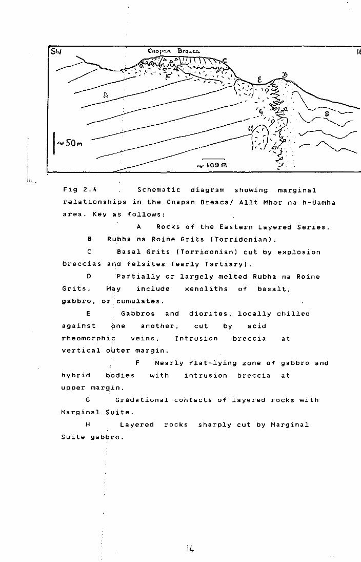
Fig 2.4 Schematic diagram showing marginal
relationships in the Cnapan Breaca/ Allt Mhor na h-Uamha
area. Key as follows:
A Rocks of the Eastern Layered Series.
8 Rubha na Reine Grits (Torridonian).
C :easal Grits (Torridonian) cut by explosion
breccias arid felsites (early Tertiary).
0 Partially or largely melted Rubha na Reine
Grits. M_,y include xenoliths of basalt,
gabbro, or 'cumulates.
E Gabbros and diorites, locally chilled
against another, cut by acid
rheomorphi~ veins. Intrusion breccia at
vertical outer margin.
F Nearly flat-lying zone of gabbro and
hybrid with intrusion breccia at
upper marg'in.
G Gradational contacts of layered rocks with
Marginal Suite.
H Layered rocks sharply cut by Marginal
Suite gabbro.
14-

vario1itic-textured gabbro rich in o1ivine. Not far
be1ow 1ayered gabbros (a11ivalites?) can be seen. A
schematic rep~esentation of the situation under Cnapan
Breaca and the:area to the south is shown in Fig 2.4.
Rhum, the
weathering
Genera11y, over most of its extent in eastern
marginal suite is very badly exposed,
to a 1ush green trench, a1though the more
dioritic and acid rocks are often rather more resistant
to weathering. Good exposures are found in the A1lt na
h-Uamha, where the river has cut through deeply
weathered gabbro. Some of the freshest gabbro specimens
have come from the cores of weathered gabbro spheroids
at this locality.
It is often difficult to distinguish the
gabbroic rocks of the margina1 suite from altered
a1livalites occurring in p1aces just within the contact.
This has led to an overestimate of the extent of the
marginal gabpro on the maps of Brown 1956) and Eme1eus
1980). The criteria used here to distinguish the two
types of r~ck are : 1. lack of layering structures in
the marginal gabbro. 2. lack of good cumulus textures in
the margin~l rocks, although large olivine phenocrysts
are occasionally seen and sub-ophitic texture is often
found. 3. clinopyroxene generally has a distinctive
granular h•bit, and often has abundant fine exolution
lamellae ~f Fe-Ti oxides in the margina1 rocks. 4.
abundance 'Of green fibrous amphibole in the marginal
rocks. 5 . Fe-Ti oxides usual1y occur as large
wel1-formed crystals in the marginal suite. 6. abundance
of quartz~rich mesostasis in even quite fresh margina1
rocks.
~he contacts of the margina1 gabbro are not
well exposed. Whi1e the intrusion breccias and acid
hybrids along the outer margin are frequently exposed
the main body of mafic and dioritic rocks cannot
generally: be seen in contact with them. The contact with
the laye~ed rocks is even more poorly exposed. In the
Allt na : h-Uamha a nearly continuous exposure through
highly weathered gabbro to allivalite can be seen but
sharp co~tacts are lacking. In the Allt Mhor na h-Uamha

the contact between the layered rocks and the marginal
suite is marked by a waterfall, and appears to be fairly
sharp. On the :north side of Beinn nan Stac peridotite
can be seen cyt by a coarse gabbro ( NM39719412), but
whether this gabbro is part of the marginal suite is not
certain. Normally the layered rocks are undeformed
towards the M~rginal Suite, however just north of the
Allt nam Ba ,. the allivalites of Unit 1 develop steep
dips to the w~st (up to 40°) near the margin.
Apart from rheomorphic veins, acid rocks are
rare within the main marginal complex. One interesting
occurrence is,a small vertically zoned body found within
gabbro at NM40679722. This consists of coarse grained
mafic diorites at the base, grading through fine grained
diorites up t~ mafic microgranite with clots of diorite
caught up in :it, all over a distance of 2.5m.
Andther acid rock, which may or may not be
genetically .linked to the marginal suite is seen at
NM40449661 .. Here a small composite sheet, 10cm to 30cm
thick is seen cutting allivalite, with a dip of 13° to
the west. T~is has felsic margins and a basic core of
basalt which is chilled against them. This is only the
second recor~ed example of an acid intrusion cutting the
layered series (Volker,1983), away from the marginal
zone.
2.0. PETROGRAPHY OF THE MARGINAL SUITE
There is a wide range of rock types
represented in this suite, from granitic and
microgranitic facies to olivine bearing gabbros with a
wide range of intermediate types. Grain size is also
highly variable, although the olivine bearing rocks are
often faitly coarse grained ( up to 5mm) and the acid
varieties rather fine grained.
For the purposes of petrographic description
the suite; will be divided into three groups: basic
types, int~rmediate types and acid types.
: ( 1) The Basic Rocks.
:These are gabbros or dolerites with or without
16

i·:
Fig 2.5 Ske~eta~ o~ivine crysta~s in vario~itic
-textured picrite. SR209A. NH39709407.
l ml'f'\
Fig 2.6 Ske~eta~ o~ivines in vario~itic-textured
gabbro. Loc 53A. NH38609549.
17

olivine. The most basic varieties are olivine-rich
gabbros and dol~rites, although these are very rare. One
such is the f~ne-grained chilled picrite seen on Beinn
nan Stac. The olivines in this rock are skeletal and
show good optical zoning (Fig 2.5), presumably due to
rapid quenchi6g, with little time for equilibration.
This may imply a late age for this picrite, as elsewhere
zoning seems to have been removed by slow annealing. A
similiar. rock (53 a), rather coarser in grain size occurs
in upper Oib~dil (Fig 2.6), although olivine zoning is
less marked. Another rock with skeletal olivines occurs
as a xenoli~h within partially melted Bagh n h-Uamha
shale (see section B.). In this case the olivines are
enclosed in plates of plagioclase and clinopyroxene (Fig
2.7); somewha~ similiar rocks occur in places within the
LELS.
Sy far the bulk of the marginal suite is
composed of gabbros, often with a little olivine.
Commonest are gabbros with subhedral olivines and
plagioclases and subophitic augite and a little
orthopyroxene ( especially rimming olivine). Euhedral or
blebby Fe-T:i oxides are common. Amphibole and biotite
may be minor phases, rimming oxides or pyroxenes. A
little quartz-alkali feldspar-rich mesostasis may occur.
Olivine is generally unzoned, at least not visibly in
thin section. Clinopyroxene generally shows zoning,
often pick~d out by a clear rim on a core showing
exsolvtion of~ opaques and plagioclase is usually
normally zoned, especially around the mesostasis areas.
Where enclosed in clinopyroxene plagioclases may be only
weakly zoned.
In the olivine-free varieties, the
clinopyroxenes normally have a distictive granular
texture (~ig 2.8) and are often clustered with oxide
grains. Twinning is common in these granular pyroxenes.
:Just NW of the summit of Beinn nan Stac,
adjacent to a large hybrid diorite exposure, abundant
loose blocks of a spectacular 'black and white' ophitic
gabbro o~cur. This rock contains no olivine, but
unusually, for the Marginal Suite, shows alkaline
18
(mm
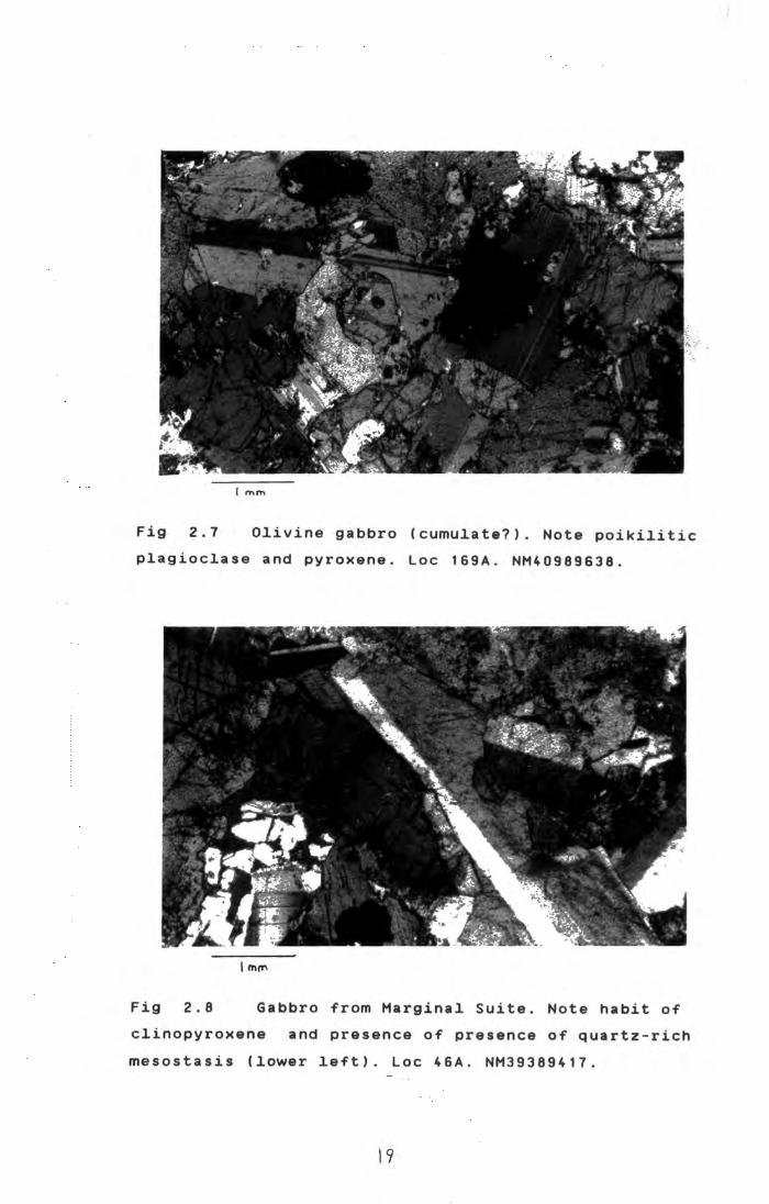
Fig 2.7 Olivine gabbro (cumulate?). Note poikilitic
plagioclase and pyroxene. Loc 169A. NM40989638.
lm~
Fig 2.8 Gabbro from Marginal Suite. Note habit of
clinopyroxene and presence of presence of quartz-rich
mesostasis (lower left). Loc 46A. NM39389417.
19
. !

, ....... Fig 2.9 Analcime-rich mesostasis with apatite (A),
sphene (S), epidote (E), and spherulitic chlorite (C)
The small dark fibres in the analcime are probably a
dark brown amphibole. Loc 47. NM39309419.
----- -------------
~\~ ·. . . -':· ·\- .: . -•• '· 4:. . -.:: ... :~. ~. ~ · ...
....lmtn
Fig 2. 1 0 Clinopyroxene altering to secondary green
fibrous amphibole (A) and biotite (B). Note also clear
rim of pyroxene on cloudy core. Loc. 1758. NM40909672.
20

Fig 2.11 Inverted tridymite crystals in melted Rubha na
Roine Grit. Note corroded clastic quartz grain (lower
right). Loc 78. NM40649731.
Fig 2.12 Microgranite with clear quartz, turbid alkali
feldspar, biotite and magnetite. Loc 1798. NM40449661.
21
affinities. The mesostasis in this rock consists of
clear analcime which includes euhedral crystals of
apatite, amphibole, epidote and spherulitic
(Fig 2.9) Almost identical assemblages have
sphene,
chlorite
been described from teschenite veins near Long Loch
(Kitchen,1985), who argued for a late-magmatic origin
for the analcime.
(2) Intermediate Rocks.
The intermediate types are marked by the
abundance of amphibole and the lack of olivine.
Frequently an acicular habit is marked, particularly in
mafic phases - this is rare in the basic varieties.
Fresh clinopyroxene is not common although much of the
amphibole is clearly secondary after clinopyroxene (Fig
2.10). Orthopyroxene is locally abundant as acicular
crystals with strong red-green pleochroism. Subhedral
grains of magnetite or ilmenite are very abundant in
some rocks but others contain very little.
(3) Acid Rocks.
These appear generally to be slightly
contaminated varieties of melted Torridonian or acid
Tertiary country rocks.
A frequent occurrence in the partially melted
Torridonian rocks is of fine grained gritty rocks with a
spherulitic texture, especially well picked out on
weathered surfaces (fig 2.2). In thin section these show
relict corroded clastic grains set in a fine grained
quartzo-felspathic matrix, often containing acicular
inverted tridymites (Fig 2.11).
The acid rock from the composite sheet is
shown in Fig 2.12. It
microgranite consisting
perthite, magnetite and
is a drusy granophyric
of quartz, rather altered
biotite. A little apatite,
pyrite and zircon are also present. Whether this is
related to the marginal suite is uncertain.
E. CONCLUSIONS
(1) The Marginal Suite is not a simple
ring-dyke. The inner and outer contacts are generally
sub-parallel and are either vertical, or dipping out
22

from the ce~tre of the central complex at low to
moderate angles. It is a complex zone containing many
distinct bodi~s of intermediate and basic rocks.
(2) The outer contact is marked by melting of I
the Torridonian sediments, and the development of
intrusion brefcias and hybrid rocks. Fragments of rocks
from the layered series are occasionally caught up in
these intrusipn breccias.
(3) Under some of the low-angle contacts
chilled picr~tes and olivine-rich gabbros are found
between hybrid rocks and the layered series.
(4)i In places the Marginal Suite may show an
intrusive relationship to the layered rocks; in others j
there is an almost insensible gradation between the two,
and the Marginal Suite may r~present a marginal facies I
to the magma chamber in which the layered rocks were
formed.
(5) There is no direct evidence that the
Marginal Sui~e occupies a ring fracture. Although it
follows gener~lly the traces of older ring fractures, in I
places it trahsgresses them.
23

CHAPTER THREE
THE LAYERED ROCKS
The LEL~ comprises some 250m of olivine and
olivine-plagioclase-(clinopyroxene) cumulates. Whereas
the upper ELS rbcks are mainly adcumulate and
heteradcumulate peridotites and troctolites, in the LELS
orthocumulates and mesocumulates are common (Brown;
1956) 1 and trocto~itic allivalite is relatively rare.
Peridotite forms t~e bulk of the upper ELS sequence; in
the LELS, about 601. of the thickness is allivalite.
Chrome-spinel I seams and harrisite layers are often
associated with ~he upper ELS peridotites, but
chrome-spinel seams are rare, and harrisites unknown in
the LELS. Many o~ the "allivalites" of the LELS are
locally rather dFficient in olivine; these gabbroic
rocks are included in the term "allivalite" to emphasise
their relationship! to the layered rocks, rather than the
later gabbro plugs and sheets. I
3.A. Sub-division pf the LELS
Brown ( 1956) divided the Eastern Layered I
Series into 15 units, each of which he considered
represented the prbducts of crystallisation of at least
one pulse of basaltic magma. Each unit he defined as
"olivine rich rock 1 passing gradually up into one rich in
plagioclase." Sam~ units present no problems in
definition: for example units 1 ,7,9,10 consist of a
peridotite layer o~erlain by an allivalite. Other units
are more complex: for example units 2,3,8,11 ,12 contain
subsidiary "units" - with thin allivalites within the ' peridotite, and/or peridotites within the allivalite. It
is thus rather arb~trary whether these are designated as
single units or as many distinct units. Brown recognised
this problem and a~gued that units should be defined on
the basis of laterally persistent dominant lithologies,
ignoring thin or impersistent layers.
Remappin~ (Fig 3.1) has revealed however that
the lateral lithological change is a common feature of

C Country rocks
p
~arginal gabbros.
diorites etc
Peridotite
Allivalite
~\\t~:~~~{K F:~: ~::i:~dUinai~er4 at
• Gabbro plugs and
' ' ' sheets
Ring fault
\... Dip of igneous layering
"
\ _Dip of sediments
Lines showing the
units as defined in the
Alit nam Ba
::>
N
I ::>
n ~5
500m
SCALE
I
~ t ! .
Ba ~ I ! .. : I
::>
D c
~ I
Fig 3 . 1 Revised map of the LELS, and stratigraphic
section. The numbers around the edge of the map are
National Grid lines at 1km intervals. The section above,
and the cryptic variation sample traverse were taken
from NM 40719452 NM40479486, and from NM 40369470
NM40109495. Note the partially expanded vertical scale
on the section.
25
225
20 0
175
150
12 5 c: 0
u .. 120 0 .. ..
• 115
D .. > 0 D
• 11 0
E
;; 0
10 5 ., ::t
100
75
50
2 5
0
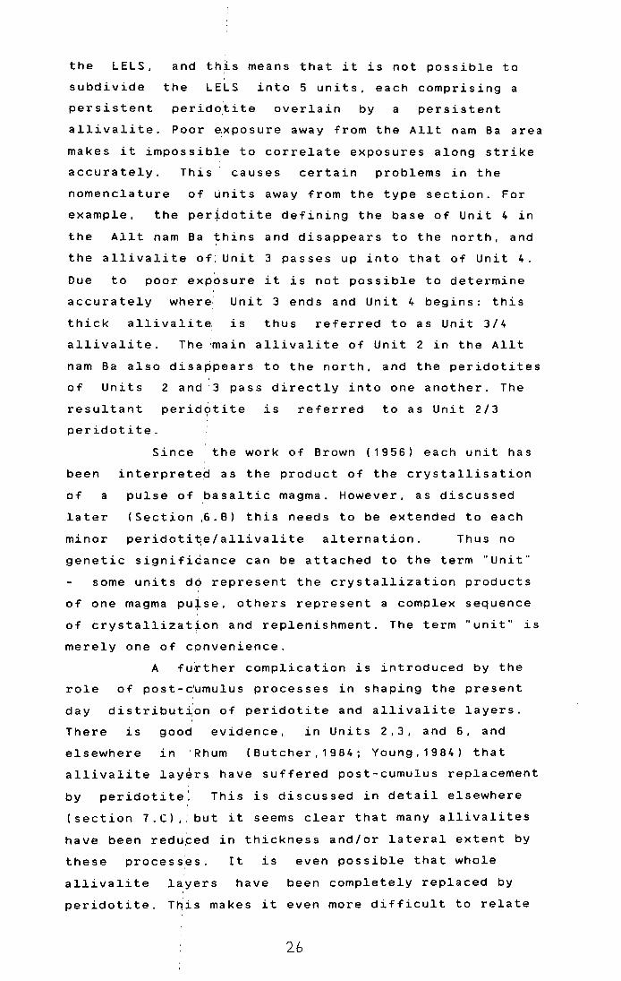
the LELS, and this means that it is not possible to I
subdivide the LELS into 5 units, each comprising a
persistent perido~ite overlain by a persistent
allivalite. Poor ~xposure away from the Allt nam Ba area
makes it impossible to correlate exposures along strike
accurately. This causes certain problems in the
nomenclature of units away from the type section. For
example, the peridotite defining the base of Unit 4 in
the Allt nam Ba thins and disappears to the north, and
the allivalite of: Unit 3 passes up into that of Unit 4.
Due to poor exppsure it is not possible to determine
accurately where: Unit 3 ends and Unit 4 begins: this
thick a 11 iva 1 it e. i s thus referred to as Unit 3/4
allivalite. The :main allivalite of Unit 2 in the Allt
nam Ba also disappears to the north, and the peridotites
of Units 2 and .3 pass directly into one another. The
resultant perid9tite is referred to as Unit 2/3
peridotite.
been
of a
later
minor
Since the work of Brown (1956) each unit has
interpretep as the product of the crystallisation
pulse of basaltic magma. However, as discussed
(Section ,6. B) this needs to be extended to each
peridoti~e/allivalite alternation. Thus no
genetic signifi~ance can be attached to the term "Unit"
some units do represent the crystallization products
of one magma pu~se, others represent a complex sequence
of crystallization and replenishment. The term "unit" is
merely one of convenience.
A fu~ther complication is introduced by the
role of post- c:umulu s processes in shaping the present
day distribution of peridotite and allivalite layers.
There is good evidence, in Units 2,3, and 6, and
elsewhere in : Rhum (Butcher,1984; Young,1984) that
allivalite lay~rs have suffered post-cumulus replacement
by peridotite: This is discussed in detail elsewhere
(section 7.C) ,: but it seems clear that many allivalites
have been redu~ed in thickness and/or lateral extent by
these processes. It is even possible that whole
allivalite layers have been completely replaced by
peridotite. This makes it even more difficult to relate
2b

the peridotite/allivalite cycles now seen to the
original cumulates
magma.
formed from distinct batches of
Bearing ~ll this in mind, the LELS has been
divided into 5 units on the basis of a measured section
in the Allt nam Ba where exposure is best. These units
are used purely for stratigraphic convenience. In view
of the considerable differences between Brown's (1956)
map and that of the current work, it is likely that not
all of the units ~efined here correspond exactly to
those defined by Brown.
3. B. Field Relations
3.B.1 Unit One
This unit can only be identified with
certainty in the Allt nam Ba. where it comprises some
20m of peridotite (base not exposed). overlain by 30m of
allivalite.
The
exposed. is
peridotite, which is rather poorly
highly .weathered. It is mostly unlayered,
although one outcrop does show a diffuse 5 - 10 em scale
layering, caused QY variations in the proportions of
intercumulus clinopyroxene and plagioclase. At NM4067
9451, it is cut by ~everal irregularly orientated coarse
gabbroic veins. Thes~ are regarded as late "squirts" of
interstitial liquid' emplaced into fractures in the
cooling cumulate p.ile. (Brown; 1956. Butcher; 1985).
Blebs of sulphide minerals up to about 1cm across are
fairly common in the peridotite.
The contact with the allivalite is exposed in
the stream bed of the Allt nam Ba, and in two small
tributary streams to the north. It seems to be sharp and
planar, although close examination is difficult due to
the steady flow of water. The basal parts of the
allivalite are poorly layered and troctolitic. Large
blebs of sulphide minerals are common in the lowest 2 -
3m, up to about 1cm across. With increasing height,
clinopyroxene becomes more abundant and the rocks
develop good layering. The layering is on a 1 -30cm
scale and is rather diffuse. reflecting slight
27

variations in cli~opyroxene content. It is best picked !
out on weathered s~rfaces.
The middle and upper parts of the allivalite
are very poor in olivine - none is seen in thin section,
although rare rusty~weathering crystals on the outcrops
suggest it may not be totally absent. This part of the I
sequence is characterised by wispy layering, with coarse
grained, well laminated clinopyroxene-rich rock I
enclosing fine grained lensoid layers of plagioclase
-rich rock.
In the topmost parts of the allivalite olivine
is again abundant, and clinopyroxene content is reduced.
Xenoliths'are not uncommon in the allivalite.
Most of these are siab-like masses of beerbachite lying
sub-parallel to the 1 layering. They are especially common
on the ridge formed:by the allivalite, just to the north
of the Allt nam Ba (about NM407957). Xenoliths are
absent from the peridotite.
To the north of the Allt nam Ba, a number of
allivalite outcrops may be tentatively described as
laterally equivalent to the Allt nam Ba sequence. The
scattered and poorly exposed outcrops at NM410955 may
belong to Unit 1; they appear to wedge out to the north.
The allivalite outc~ops in the Allt na h-Uamha may also
be equivalent, although they are rather more
feldspar-rich and ,clinopyroxene-poor compared to the
Allt nam Ba sequence:. Just inside the marginal gabbro in
the Allt Mhor na h-U~mha, a small outcrop of allivalite
underlies peridotite:; it resembles the allivalite of the
upper part of Uni~ 1, although it is only faintly
layered.
3.8.2 Unit Two
Of all the units in the LELS, Unit 2 bears the
greatest resemblance to those of the upper ELS.
Peridotite is predominant over allivalite (50m of
peridotite; about 15~ of allivalite) and the allivalite
is a clinopyroxene-poor troctolite.
The Unit has a slightly undulating or nearly
planar contact with the underlying allivalite of Unit 1,
28

I
Fig 3.2. Finger structures cutting low-angle slump folds I
in unit 2 allivalit'
Fig 3.3.
disrupted
peridotite
:
p 1 rt of unit 2 allivalite heavily I
by finget structures. The honeycomb-textured '
above t~e overhang is unit 3 sensu stricto.
The underlying, more feldspathic rock includes unrotated I ,
relict blocks of aliivalite. Loc 198. NM40549478.
29

well exposed in several of the streams comprising the
Allt nam Ba. There 'is no basal chrome spinel seam. A few
metres above the b~se an allivalite layer is developed.
This layer is quite thick
but
and coherent in the
southernmost exposures to the north it becomes ' increasingly disturbed, being mixed with the enclosing
peridotite by slumping and loading. Although exposures
are not particularly good, the slump folds appear to
have no constant closure directions, and hence slumping
caused by down-slope movement is less likely than
deformation under conditions of fluidisation perhaps
There is also a suggestion of induced by
along-strike lithplogical change in this layer. The
material which has been mixed in with peridotite is well
laminated and poor. in clinopyroxene, while the coherent
outcrops to the south show little lamination and are
richer in clinopyroxene.
Above this deformed layer is a considerable
(25m +) thickness of poorly exposed peridotite, which is I
unlayered or show~ a 5 - 15cm scale diffuse layering on
weathered It is overlain by a thin (3m)
disturbed
surfac~s.
layer ,of troctolitic allivalite, rather
discontinuous along strike. The upper surfaces of many I
of the peridotite loads within this layer show the
development of finger structures. This allivalite is
only seen between'NM40489460 and NM40629472.
The upp~r part of Unit 2 peridotite above this
layer consists of I
14m of well layered honeycomb
peridotite, rather more feldspathic than the peridotite
lower down in the' unit.
The main allivalite of Unit 2 in the Allt nam
Ba shows eviden~e of a complex history. The bottom
contact
sharp.
is not well exposed but seems to be planar and
In the exposures at NM40509474, the allivalite
contains three th~n peridotite layers which are not seen
to the south. Ea~h of these has a sharp planar base no I
chrome spinel seams) and an upper surface marked by
upward protrusions of peridotite into allivalite -
hereafter referied to as finger structures. The
allivalite above the lowest peridotite has well
30
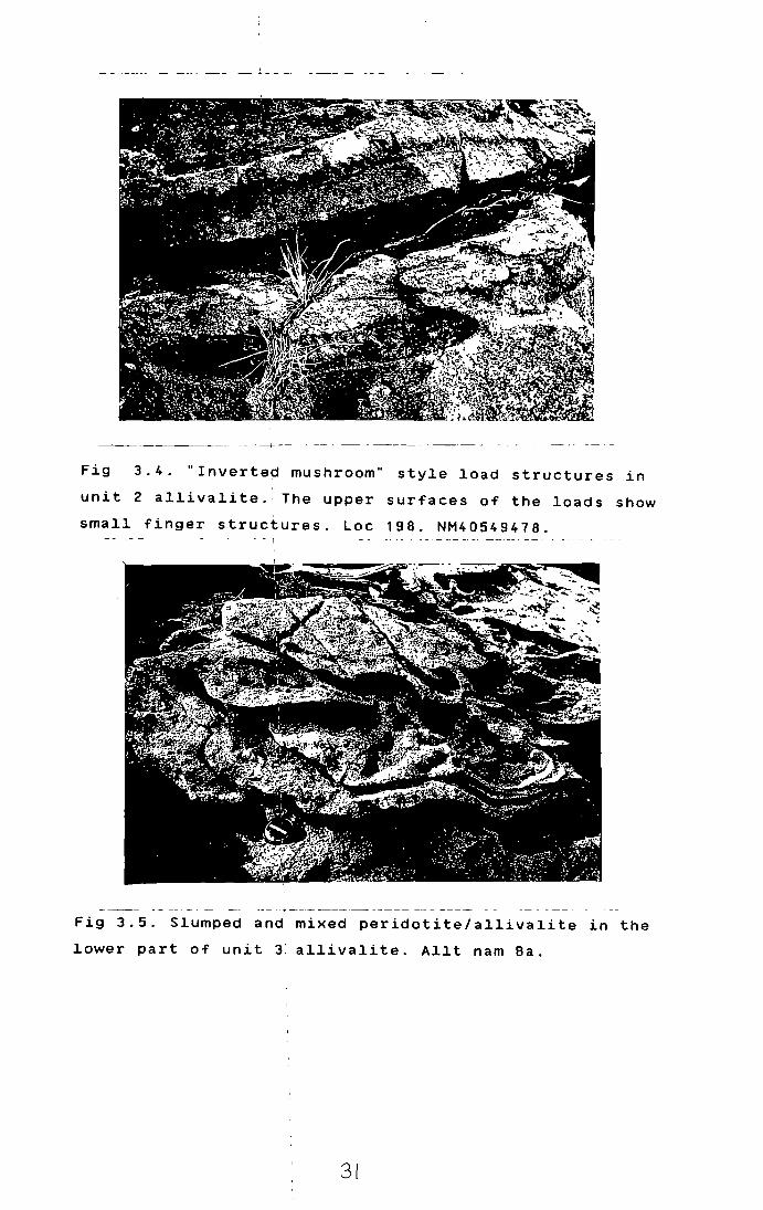
Fig 3.4. "Inverted mushroom" style load structures in
unit 2 allivalite. The upper surfaces of the loads show
small finger structures. Loc 198. NM40549478. - - i
Fig 3.5. Slumped and mixed peridotite/allivalite in the
lower part of unit J: allivalite. Allt nam Ba.
31

developed recumbent slump folds - these are sharply cut
across by the finger structures (Fig 3.2). A little to
the north these peridotites thicken somewhat, and
deformation becomes marked, with the peridotite layers
becoming local~y discontinuous due to loading, with
flame structu~es of allivalite injecting the
peridotites. Finger structures are more prominent than
they are furth~r south. A few tens of metres further
north, the allivalite presents a different spectacle
(Fig 3. 3 ). The upper part has been extensively disrupted
by finger develqpment, with merging of the subsidiary
peridotites leaving only a few relict fragments of
allivalite. All' these relict fragments have their
lamination and ~ayering parallel to the general dip of
the layering. T~e peridotites often show "inverted
mushroom" style ~oad structures, the upper surfaces of
which show the d¢velopment of small fingers (Fig 3.4).
These structures,. and other similar ones are abundant in
Rhum, and they are taken as evidence of replacement
(Robins, 1982; Butcher et al, 1985). They are discussed
in more detail in ,section 7. C.
The mai~ allivalite of Unit 2 cannot be traced
north beyond NM409.49540, and the peridotites of Units 2
and 3 cannot be a~curately distinguished. However, in
the stream around: NM408964, a number of small isolated
allivalite outcrops are seen, which may perhaps be
ascribed to Unit 2.
3 • B • 3 Unit Three
Unit 3 is the most extensive in the LELS,
exhibiting consid~rable lateral changes in lithology.
The boundary with Unit 4 is only clear-cut in the
southern part of tre area; to the north the allivalite
of Unit 3 merges with that of Unit 4 due to the
northward thinning of Unit 4 peridotite. In the measured
section in the Allt nam Ba the unit is about 36m thick,
of which 23m is allivalite.
The conta~t with Unit 2 is well exposed in the
Allt nam Ba, and ·is sharp and planar, except where
finger structures (see previous section) have cut
32

Fig
part
s1ab.
Fig
3.6. Fine-gr~ined p1agioc1ase rich 1ayer in 1ower
of unit 3 a ~1ivalite. Note deformed margins. Cut
Approximate l y 1ife size. Loc 183. NM40799620.
3.7. Deformed •xenolith• of troctolitic allivalite
in c1inopyroxene-~ich a11ivalite of unit 4. Xenolith
approx. 0.4m long. Loc 184. NM40739613.
33

. i . L'·; .
',, •:·t I ... . ' ·'
'" !'
\l'.l :. 'I
I I.' ,. •.:·
;J
' . . ,·

through the underlying allivalite. Th~re is no chrome
s pi n e 1 s e am . A b!o u t 2m a b o v e t he b a s e i s a t h in .
discontinuous a n~d high 1 y d i s t u r bed all iva 1 it e 1 a y e r . A
this is a small anorthositic allivalite metre above I
layer with small' (ca. 1cm) finger structures along its
base. This layeJ shows no sign of deformation. The top
surface is sha~p and planar and is overlain by 5m of
honeycomb-weathered peridotite. Above this is 27m of '
allivalite. The lowest parts are highly deformed, with
schlieren and !lenses of peridotite, which slightly
further up for~ a slightly more coherent layer (Fig
Above this the allivalite becomes increasingly 3. 5).
rich in 1. I c J.nopyroxene and less well laminated. The
pyroxene-rich up~er parts have a vague layering on a 5cm
1m scale, pick~d out by variations in pyroxene content '
and the presence or absence of large (1cm) poikilitic
olivines. This 1same part of the sequence is prone to
crumbly weatheri~g and has a rather altered appearance.
This may be related to a nearby gabbro intrusion (see
next section).
The peridotite of Unit 3 is not well exposed
to the north of the Allt nam B~. and north of NM 4.0'YI'i4. ·,t merges with that of Unit 2. Exposures at NM40859621 show
peridotite overlying a thin troctolite layer. The upper
part of this 1ayer is anorthositic and has a
chrome-spinel seam developed along the top of it. Two I
thinner, and rather deformed chrome-spinel seams occur
within the periddtite one or two em above. These are the
only chrome-spi~el seams seen in the LELS, and this is
the only place where peridotite overlies anorthositic
allivalite. The ~ssociation of chrome-spinel seams with
anorthosite-peridotite contacts is a marked feature of I
the ELS, the contacts between Units 7 and a. and Units
11 and 12 being Jood examples.
To the north of the Allt nam Ba the
troctolitic lower part of Unit 3 allivalite is less well I
developed, and clinopyroxene is a major phase I
throughout. Minor peridotite layers do occur in the
lower
with
parts, but it is not possible to correlate these
those seen in the Allt nam Ba. Good exposures of I
34

the main allivalite can be seen in the lower parts of
the cliff 300m NNE of Loch Caire nan Grunnd. At
NM40799620 abundant lensoid layers of fine grained
anorthositic material can be seen. These layers are
generally 1-5cm thick, and can be traced along strike
for up to a meter or so. They have sharp, although often
deformed contacts with the material above and below (Fig
3.6). A little further up the cliff, at NM40759625, an
unusual (for Rhuml channel-like structure can be seen.
This contains a number of dish-like layers, separated by
erosive(?) surfaces. The axis of the channel dips at 24°
to the WSW, about the same as the adjacent rocks. These
dish-like layers ~re stacked approximately vertically,
and extend several meters up the cliff face. Although
the upper parts are somewhat inaccessible, they appear
to be richer in olivine than those lower down. The width
of the "channel" is difficult to gauge due to the
steepness of the terrain, but is at least 10m.
In the Allt Mhor na h-Uamha, at NM40369716, a
fine-grained clinopyroxene rich layer contains abundant
tiny blebs of sulphide minerals.
Xenoliths of beerbachite are not uncommon in
the middle and upper parts of Unit 3 allivalite.
3.8.4 Unit Four
The peridotite which defines the base of Unit
4 in the Allt nam Ba is very thin (<3m). Where it is
best exposed, around NM40489483, it has a very weathered
and altered appearance. Veins of gabbro are common in
this area, and it may be that a sub-surface gabbro
intrusion has af.fected the cumulates. To the south the
peridotite becomes rather fresher in appearance, while
to the north it thins and cannot be traced north of
NM40519485.
The peridotite has a sharp and planar contact
with the overlying allivalite, which is a well layered
troctolitic type, at least in the Allt nam Ba. This
passes into poorly layered clinopyroxene and Fe-Ti oxide
rich material with abundant xenoliths of beerbachite,
gabbro and ultrabasic rocks. To the north of the Allt
35

nam Ba the troctolitic facies is not well developed, and
the orthocumulates of the upper part of Unit 3 pass up
into those of Unit 4 with no clear boundary.
This part of Unit 4 allivalite to the east of
Loch Co ire nan Grunnd
allivalite
contains "xenoliths" of
troctolitic set in a clinopyroxene rich
cumulate. These xenoliths were obviously in a soft
plastic stage as they are deformed and folded in with
the enclosing material (Fig 3.7). Above these deformed
cumulates in this area are undeformed, w0ll layered
orthocumulates with layers rich in magnetite. Epidote is
common as an interstitial mineral in certain layers.
This facies is not developed elsewhere: generally the
xenoliths become more abundant with height until
suddenly
about 2m.
there is a sharp decrease in grain size over
The upper part of Unit 4 allivalite over its
entire exposed length is comprised of this fine grained
facies. Just below this fine-grained layer in the Allt
nam Ba at NM404948 a thin ( - 2m ) peridotite layer
occurs, cut by abundant gabbro veins like those seen at
the base of Unit 4 nearby.
This fine- grained layer is very rich in
xenoliths and was mapped by Brown (1956) as an intrusive
sheet of olivine gabbro, although he seems to have used
the presence of xenoliths to delineate its contacts,
thus obscuring the fact that xenoliths appear much lower
down in the sequence than the fine-grained rock types.
Brown states that " ( the gabbro] .... is free from any
form of banding or igneous lamination ... ".
Re-examination during the course of the present work
however, has revealed that abundant vague wispy
layering, and lam~nation of plagioclase is also common.
The conformable, gradational nature of the bottom
contact and the presence of xenoliths in both the
underlying allivalite and in the fine-grained layer may
cast doubt on an intrusive origin for this body of rock.
A preliminary examination of the Askival
Plateau Gabbro (AP~ ) , a body of rock superficially
resembling the fi.ne grained facies in Unit 4, show it to
be clearly intrusive with abundant net-veined contacts.
3b
The AP~ clearly cross-cuts the layering of Units 9
and 10, and has caused considerable deformation of the
layering in these ' units. Butcher ( 1984) in a more
detailed study also ~ound a ghost stratigraphy preserved
in the .AP~ based ~n the distribution of xenoliths.
None of these features are seen in the fine
grained layer of Unit 4, suggesting a different origin,
although the litho~ogies are very similar even down to
the presence of layering within the AP~
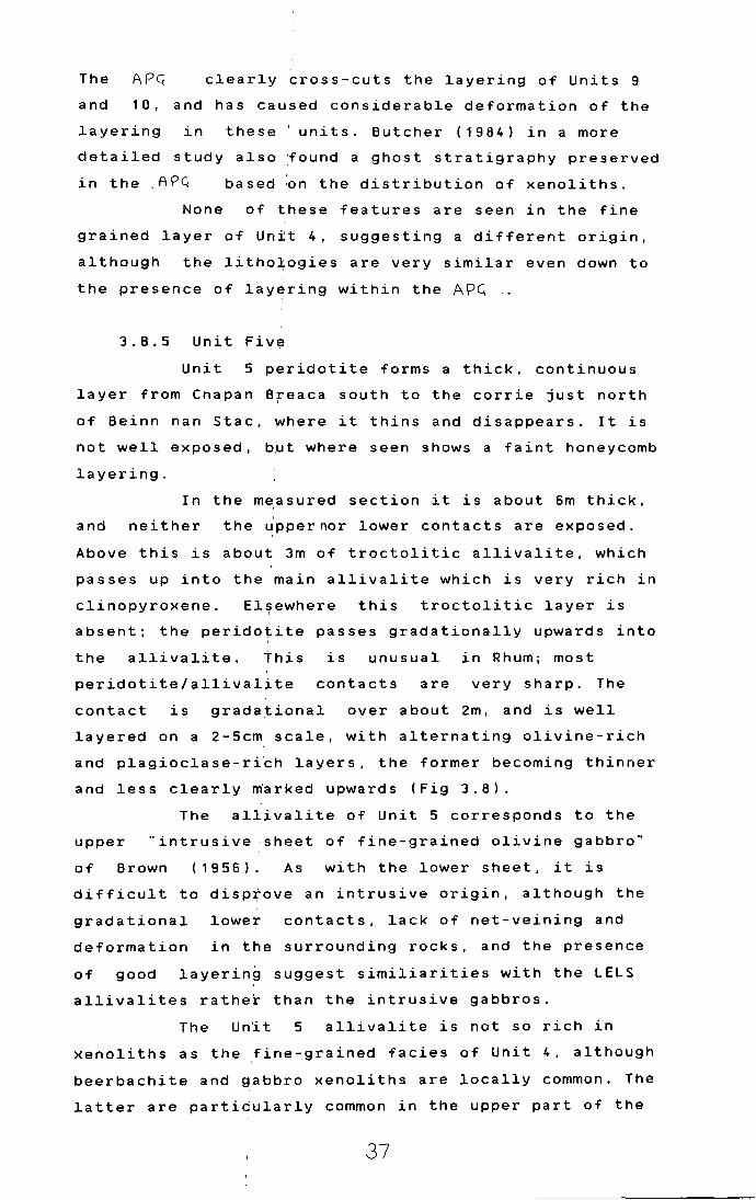
3 . B • 5 Unit Five
Unit 5 peridotite forms a thick, continuous
layer from Cnapan Breaca south to the carrie just north
of Beinn nan Stac, where it thins and disappears. It is
not well exposed, b~t where seen shows a faint honeycomb
layering.
In the m~asured section it is about 6m thick,
and neither the Jppernor lower contacts are exposed.
Above this is about 3m of troctolitic allivalite, which
passes up into the main allivalite which is very rich in
clinopyroxene. El~ewhere this troctolitic layer is
absent; the peridotite passes gradationally upwards into '
the allivalite. This is unusual in Rhum; most
peridotite/allivalite contacts are very sharp. The
contact is gradational over about 2m, and is well
layered on a 2-5cm scale, with alternating olivine-rich
and plagioclase-ri~h layers, the former becoming thinner
and less clearly ~arked upwards (Fig 3.8).
The allivalite of Unit 5 corresponds to the
upper "intrusive .sheet of fine-grained olivine gabbro"
of Brown (1956). As with the lower sheet, it is
difficult to disprove an intrusive origin, although the
gradational
deformation
lower I
contacts, lack of net-veining and
in the surrounding rocks, and the presence
of good layering suggest similiarities with the LELS
allivalites rather than the intrusive gabbros.
The Un'i t 5 allivalite is not so rich in
xenoliths as the ,fine-grained facies of Unit 4, although
beerbachite and gabbro xenoliths are locally common. The
latter are particularly common in the upper part of the
37

Fig 3.8. Gradational contact between unit 5 peridotite
and allivalite. Height of outcrop approx. 1m. Loc 178.
NM40179674.
Fig 3.9. Layering in unit 5 allivalite. An ilmenite
-rich layer occurs along the line marked X-X. This
trucates the underlying layering in places (A). Loc 203.
NM40149483.
38
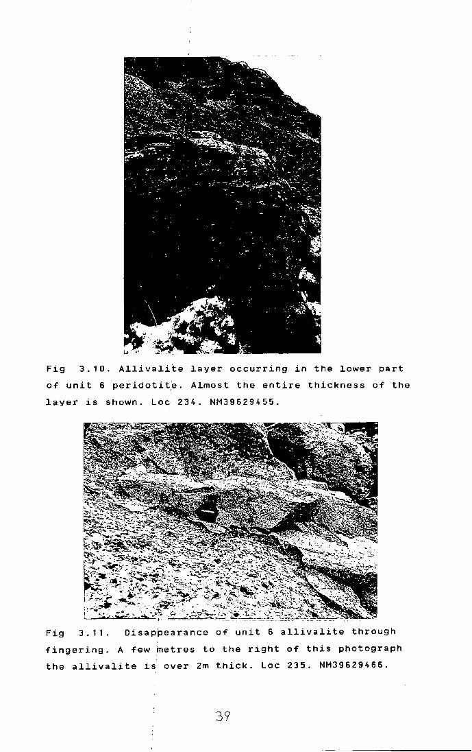
Fig 3.10. Allivali~e layer occurring in the lower part
of unit 6 peridotit~. Almost the entire thickness of the
layer is shown. Loc 234. NM39629455.
Fig 3.11. Oisap~earance of unit 6 allivalite through
fingering. A few metres to the right of this photograph
the allivalite is over 2m thick. Loc 235. NM39629466.
39

allivalite in Bare :carrie
frequently magnetic.
(NM398971); they are
Layering is well developed in places within
Unit 5 allivalite, mostly rather diffuse and without
dramatic changes in. modal mineralogy between layers.
Locally however, sttiking concentrations of ilmenite
occur as thin layers (Fig 3.9). At this locality the
oxide-rich layer app~ars to divide around a beerbachite
xenolith, and there is a suggestion of an unconformable
contact, the oxide-r~ch layer cutting of~ the underlying
layering which has a:slightly steeper dip.
In the measured section, Unit 5 allivalite
contains a thin lens9id peridotite layer about 10m below
the top.
contact,
This peridotite has a gradational lower
and a fairiy sharp upper contact. It displays
excellent laminatidn of elongate olivines in its basal
portions.
The uppe~ part of Unit 5 allivalite develops
in places (eg NM39699718) a rather pale, well layered
facies. Brown (1956) interpreted these as relics of the
allivalite which had been intruded by the sheet, but
explicit evidence !for this is lacking. A very similiar
facies is developed: in Unit 8 allivalite at NM94859683.
Brown ' s '( 1 9 56) map shows the "'upper sheet"'
cutting across the :allivalites of Units 5, 6 and 7 below
Clough's Crag, a~d used this as evidence for the
intrusive nature .of the sheet. However the sheet is
nowhere seen in contact with the allivalites, and
lateral wedging o~t of the layers (seen at eg NMl is a
more likely explanation.
Between ~he top of Unit 5 allivalite and Unit
6 allivalite at NM, a previously unmapped allivalite
layer occurs. It ~s of distinctive appearance, the lower
part being troctolitic with scattered large green
clinopyroxene oikocrysts, and the upper part being much
finer grained a~d richer in pyroxene (Fig 3.10). One
might be tempted to term this Unit 5.5, but for the sake
of terminological simplicity. and to avoid setting
dubious precedents, it is perhaps better included as a
sub-unit of unit :6 .
4-0

The main allivalite of unit 6 is highly
discontinuous along strike, due to the "fingering"
process mentioned eariier (3.8.2). This is shown in Figs
3 . 1 1 and 3 . 1 2 .
numbers
3.8.6 Gabbr~ plugs and sheets
Previous m•ps of the LELS have shown differing
of small ~abbro intrusions in a variety of
places. Much of th~s confusion has stemmed from the
rather "gabbroic" appearance of the LELS rocks, together
with the extent of l~teral lithological variation, which
was not previosly recognised. Most of these have been
reinterpreted as clinopyroxene-rich allivalite in the
present work. However, several small plugs and inclined
sheets of gabbro 'have been mapped on the basis of
transgressive or chilled margins and lack of layering.
Two of these are intruded across the upper contact of
unit 5 allivalite,. cutting both it, and the overlying
peridotite.
3.C. PETROGRAPHY
Good accounts of the petrology of the LELS are given by
Brown (1956) and H~rker (1908). For the sake of brevity,
and to
account,
avoid excessive duplication, only a general
together. with some new observations, will be
given here.
3.C.1 Peridotites
The peridotites are composed of four main
minerals: olivine, plagioclase, clinopyroxene, and
chrome-spinel. Olivine and chrome-spinel are the only
cumulus phases. Other minerals occur in small
quantities: phlo;'gopi te, kaer s uti te, orthopyroxene,
hornblende, various sulphide minerals, and a variety of
secondary alteration products such as chlorite, talc(?),
and serpentine.
3.C.1.a Textures
Olivine forms between 40Z and 80Z by volume of the LELS
peridotites. T~e dunitic facies locally developed in
41

Fig 3.12. View 1oo~ing down on fing rs in unit 6. Same
1oca1ity as previou~ photograph. L -- --- ~
I M$'\
Fig·--3-.-1-3- .- Fe1dsfpathi-c - per-idotite with 1ow density of
o1ivine crysta1~. Note high proportion of intercumu1us
materia1 and non ~ touching grains. PPL. Samp1e U2P11. '
42

other parts of the ultrabasic complex are not seen in
the LELS. Some of the rocks seen in the peridotite
layers of the LELS'are not strictly peridotites, being
rather deficient in olivine, however they are included
here on the basis o~ association, and in the absence of
cumulus plagioclase. Indeed, according to some
definitions, certain of the peridotites would not be I
regarded as cumul~tes at all, as the cumulus grains
(olivine) do not form a touching crystal framework
(Fig 3.13 l. However,. in view of their close association
with rocks of impec~able cumulate credentials, and the
fact that they are c~early not representative of liquid
compositions, this is not considered crucial. According
to McKenzie (1985), Fompacting layers of olivine+ basic
melt may well devel~p upward-moving melt-rich "waves"
with non-touching grains. This is a plausible process in
layered intrusions (Sparks et al, 1985), and this may
account
textures.
Donaldson
for the local absence of grain supported I
A similiar process has been invoked by
(1982) to explain the formation of certain
harrisite layers.
Olivine ctystals tend to be smaller and more
widely spaced when enclosed in clinopyroxene oikocrysts
than when enclosed in plagioclase (Fig 3.14). This is at
first sight somewhat paradoxical, as clinopyroxene
normally crystallis•s after plagioclase in Rhum. Thus
early crystallising ' plagioclase might be expected to '
preserve the high- p1oro sit y, uncompacted cumulus
textures,
olivines,
crystallise
and preve~t further growth of the enclosed
while the' later-formed pyroxene would I
in the interstices of better compacted,
larger grains. A number of factors may be significant
here. Delayed nucleation of plagioclase, so that it i
nucleates simultaneously with pyroxene, has been I
suggested by McClurg (1982) as an explanation for
enhanced Al2o
3 conte~ts of CS clinopyroxenes. There is
some evidence that Al203
contents of LELS clinopyroxenes
tend to be higher than those of the upper ELS (section),
however this textura~ phenomenon has been observed by
Volker (1983) in many upper ELS peridotites, so this is

lmm
Fig 3.14. Peridotite from unit 5, showing small size and
wide spacing of olivines within clinopyroxene. PPL.
Sample U5A17i.
o ·S"ml'tl
Fig 3.15. Peridotite from unit 5. Note break-up of
elongate olivines into trails of small blebs as they
cross from plagioclase oikocryst to clinopyroxene
oikocryst. XP. Sample U5A17ii.
44
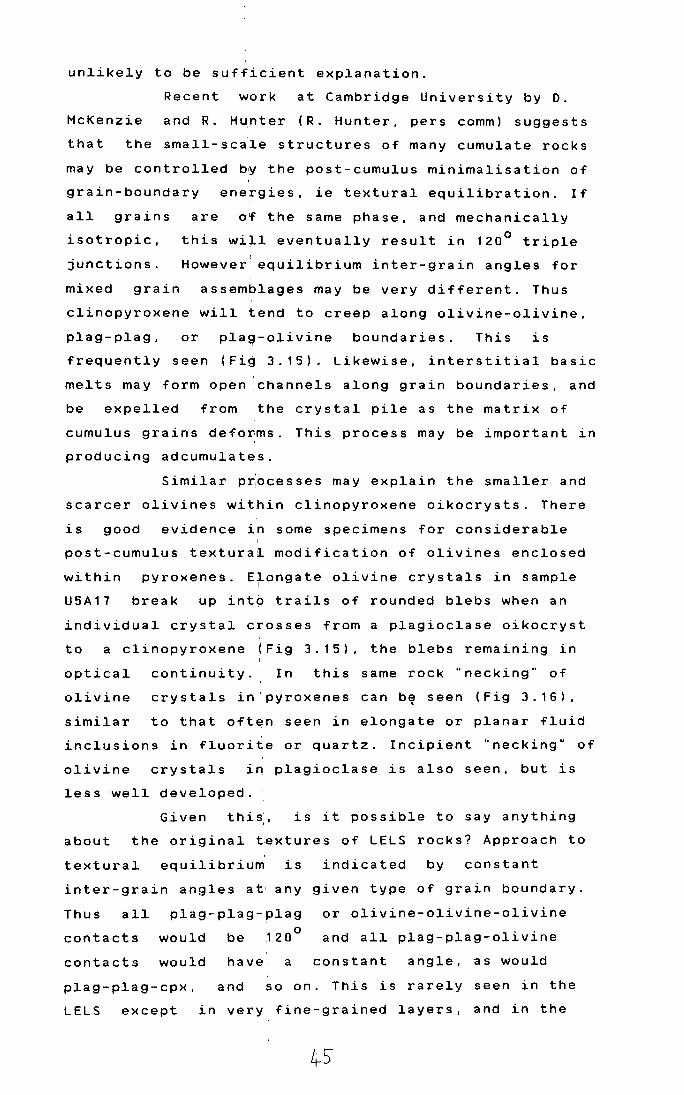
unlikely to be sufficient explanation.
Recent work at Cambridge University by D.
McKenzie and R. H~nter (R. Hunter, pers comm) suggests
that the small-sca.le structures of many cumulate rocks
may be controlled by the post-cumulus minimalisation of
grain-boundary energies, ie textural equilibration. If
all grains are of the same phase, and mechanically
isotropic, this wi~l eventually result in 120° triple
junctions. However equilibrium inter-grain angles for
mixed grain assemblages may be very different. Thus
clinopyroxene will tend to creep along olivine-olivine,
plag-plag, or plag-olivine boundaries. This is
frequently seen (Fig 3.15). Likewise, interstitial basic
melts may form open channels along grain boundaries, and
be expelled from ·the crystal pile as the matrix of
cumulus grains deforms. This process may be important in
producing adcumulat~s.
Similar p~ocesses may explain the smaller and
scarcer olivines within clinopyroxene oikocrysts. There
is good evidence in some specimens for considerable
post-cumulus texturai modification of olivines enclosed
within pyroxenes. Elongate olivine crystals in sample I
U5A17 break up into trails of rounded blebs when an
individual crystal crosses from a plagioclase oikocryst
to a clinopyroxene (Fig 3.15), the blebs remaining in
optical continuity. In this same rock "necking" of
olivine crystals in'pyroxenes can b~ seen (Fig 3.16).
similar to that often seen in elongate or planar fluid
inclusions in fluorite or quartz. Incipient "necking" of
olivine crystals in plagioclase is also seen, but is
less well developed. :
Given this,, is it possible to say anything
about the original ~extures of LELS rocks? Approach to
textural equilibrium is indicated by constant
inter-grain angles at' any given type of grain boundary.
Thus all plag-plag-plag or olivine-olivine-olivine
contacts would be 120° and all plag-plag-olivine
contacts would have a constant angle, as would
plag-plag-cpx, and so on. This is rarely seen in the
LELS except in very fine-grained layers, and in the

Fig 3.16. Peridotite from unit 5. Note "necking" and
break-up of elongate olivine at point A. XP. Sample
U5A17ii.
\mM ------- --- -~ ~------ ------------ ----- --- --
Fig 3.17 Peridotite from unit 2 showing very local
development of 120° triple junctions between olivine
grains. XP. Sample U2P9.

Fig
unit
3.18. Intersrcting laminations in peridotite from
5. Olivine~ parallel to the bottom of the
photograph are in extinction. XP. Sample U5A17iii.
lft\m ~---~ -~---
Fig 3.19. Prefer.ntial concentration of chrome-spinel I
crystals on the ~pper surfaces of olivine crystals in
peridotite from u~it 2. PPL. Sample U2P5.
47
' --:·
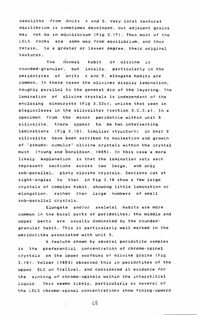
xenoliths from ;Units 4 and 5. Very local textural
equilibrium is sometimes developed, but adjacent grains
may not be in equilibrium (Fig 3.17). Thus most of the
LELS rocks are some way from equilibrium, and thus
retain, to a gr~ater or lesser degree, their original
textures.
The riormal
rounded-granular, but
habit
locally,
of olivine is
particularly in the
peridotites of units 4 and 5, elongate habits are
common. In these cases the olivines display lamination, ' '
roughly parallel 'to the general dip of the layering. The
lamination of ~livine crystals is independant of the !
enclosing oikocrysts (Fig 3.32c), unlike that seen in
p 1 a g i o c 1 a s e s in t1h e a 11 i v a 1 i t e s ( s e c t ion 3 . C . 3 . a ) . I n a
specimen from the minor peridotite within unit 5
allivalite,
laminations
ther:e appear to be two intersecting
(fig 3.18). Similiar structures in Unit 9
allivalite have been ascribed to nucleation and growth
of "pseudo- cumulus" olivine crystals within the crystal I
mush (Young and Donaldson, 1985). In this case a more
likely explanation is that the lamination sets each
represent t. i
sec 1ons across two large, and only
sub-parallel,
right-angles
pl~ty olivine crystals. Sections cut at I
to that in Fig 3.18 show a few large
crystals of compl~x habit, showing little lamination or
elongation, rather than large numbers of small
sub-parallel crys~als.
Elongate and/or skeletal habits are more
common in the bas~l parts of peridotites; the middle and
upper parts are usually dominated by the rounded-
granular habit. This is particularly well marked in the
peridotites associated with unit 5.
is the
crystals
A feature shown by several peridotite samples
preferential concentration of chrome-spinel i on the upper surfaces of olivine grains (Fig
3.19). Volker (19~3) observed this in peridotites of the I
upper ELS on Trailval, and considered it evidence for
the sinking of c~rome-spinels within the interstitial
liquid. This seems likely, particularly as several of
the LELS chrome-s~inel concentrations show fining-upward
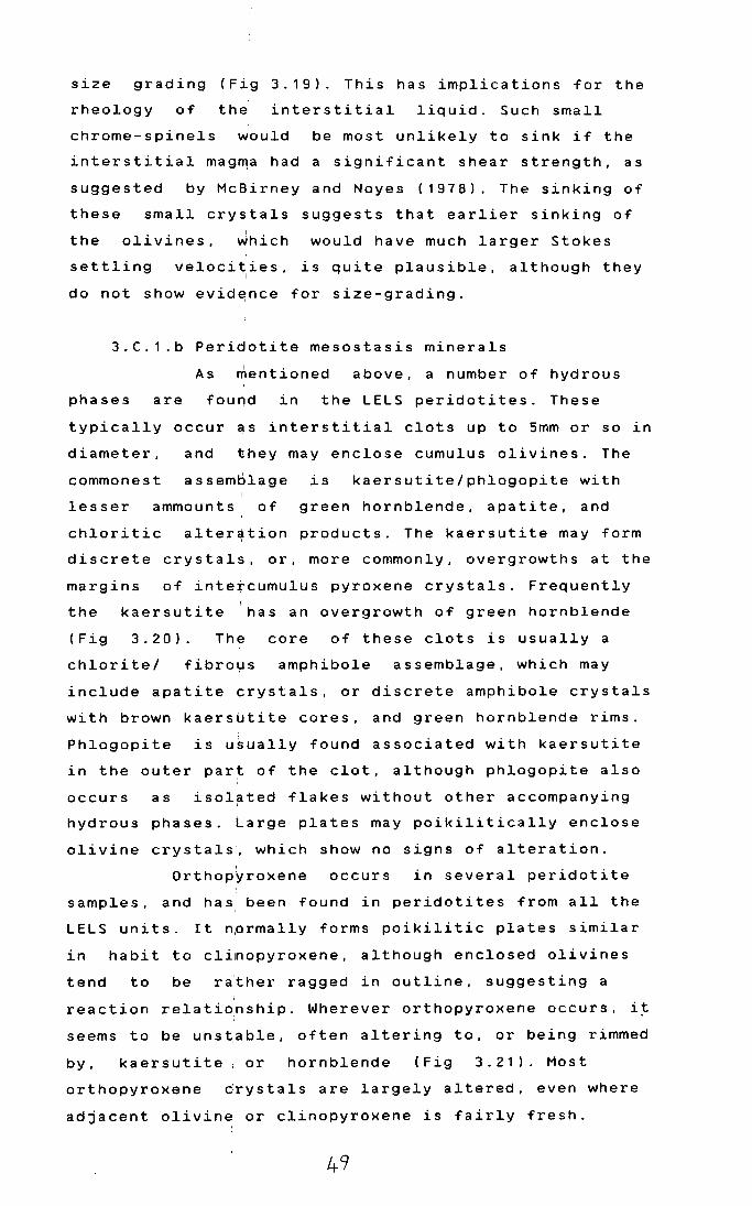
size grading (Fig 3.19). This has implications for the
rheology of the interstitial liquid. Such small
chrome-spinels would be most unlikely to sink if the
interstitial mag~a had a significant shear strength, as
suggested by McBirney and Noyes (1978). The sinking of
these small crystals suggests that earlier sinking of I
the olivines, which would have much larger Stokes
settling veloci~ies, is quite plausible, although they
do not show evid~nce for size-grading.
3.C.1.b Peridotite mesostasis minerals
As mentioned above. a number of hydrous
phases are found in the LELS peridotites. These
typically occur as interstitial clots up to Smm or so in
diameter, and they may enclose cumulus olivines. The
commonest assemblage is kaersutite/phlogopite with
lesser ammounts of green hornblende, apatite, and
chloritic alter~tion products. The kaersutite may form
discrete crystals. or, more commonly, overgrowths at the
margins of intercumulus pyroxene crystals. Frequently
the
(Fig
kaersutite has an overgrowth of green hornblende
3. 2 0) . The core of these clots is usually a
chlorite/ fibrot,.~s amphibole assemblage, which may
include apatite crystals, or discrete amphibole crystals
with brown kaersutite cores, and green hornblende rims.
Phlogopite is usually found associated with kaersutite
in the outer part of the clot, although phlogopite also
occurs as isolated flakes without other accompanying
hydrous phases. Large plates may poikilitically enclose
olivine crystals, which show no signs of alteration.
Orthopyroxene occurs in several peridotite
samples. and has, been found in peridotites from all the
LELS units. It nprmally forms poikilitic plates similar
in habit to clinopyroxene, although enclosed olivines
tend to be ra:ther ragged in outline. suggesting a
reaction relationship. Wherever orthopyroxene occurs. i~
seems to be uns~able, often altering to, or being rimmed
by, kaersutite, or hornblende (Fig 3.21). Most
orthopyroxene drystals are largely altered, even where
adjacent olivin~ or clinopyroxene is fairly fresh.
49

-~----- -- ~- --- ~ ~---r---------------~--- -----
Fig 3.20. Hydrous minerals in peridotite from unit 2.
Clinopyroxene (c) has overgrowth of kaersutite (k),
which in turn has ,a rim of green hornblende (h). A large
flake of phlogopite (p) is also visible. PPL. Sample
U2P11.
-------1--- ----~------------ --
Fig 3.21. Interst~tial orthopyroxene crystal being made
over to hornblende, kaersutite, and chlorite. XP. Sample
U1P4.
50

Further 'indications of late-stage liquids
available in the• peridotites are provided by veins
cutting the perid~tites of units 1 and 2/3. These are
coarse-grained and unchilled, and are very similar in
appearance
described
the veins
to the "contemporaneous ultrabasic veins"
by Brown (1956) and Butcher (1985). However
examined in the LELS are all highly
fractionated. and' are teschenitic or syenitic rather I
than ultrabasic. They all have clinopyroxene, as large I
neutral-coloured irregular crystals, which may be rimmed
by dark-blue amphibole or chlorite (Fig 3.22). alkali
feldspar, and abundant Fe-Ti oxides. Some veins have
abundant plagioclase, showing intense normal zoning over
a more homogeneous calcic core; in others perthitic
alkali
widely
(Fig
feldspar ~s dominant. Zircon and sphene occur
in small quantities; apatite is very abundant
3. 2 3) ; a pa~e greenish yellow mineral with high
and straight extinction forming tiny birefringence
elongate crystals •: and more rarely. thin overgrowths on
clinopyroxene may' be aegirine. Kaersutite is not
uncommon, usuall~ as small inclusions within the large
clinopyroxene cr~stals. Fibrous zeolites and possibly
analcime also occur in small quantities. Kitchen (1985)
has described sim~lar veins in CS peridotites from near
Long Loch. The presence of both silica oversaturated
(orthopyroxene) and undersaturated alkaline (kaersutite,
analcime, aegirine) assemblages associated with LELS
peridotites is cu~ious. The alkaline assemblage seems to
be later, in that orthopyroxene is out of equilibrium
wherever seen, being made over to the amphibole-rich
assemblage. The l~quids available at very late stages to
form veins when'the peridotites were cool enough to
undergo brittle fracturing are thoroughly alkaline.
3.C.1 .c Sulphide minerals
Sulphid~ minerals are not uncommon in trace
quantities in Rhum peridotites (Volker. 1983), however
unit 1 of the LEL$ is strikingly rich in sulphide blebs
of large size, which may form 5Z of the rocks.
The sulphide minerals in unit 1 peridotite
51
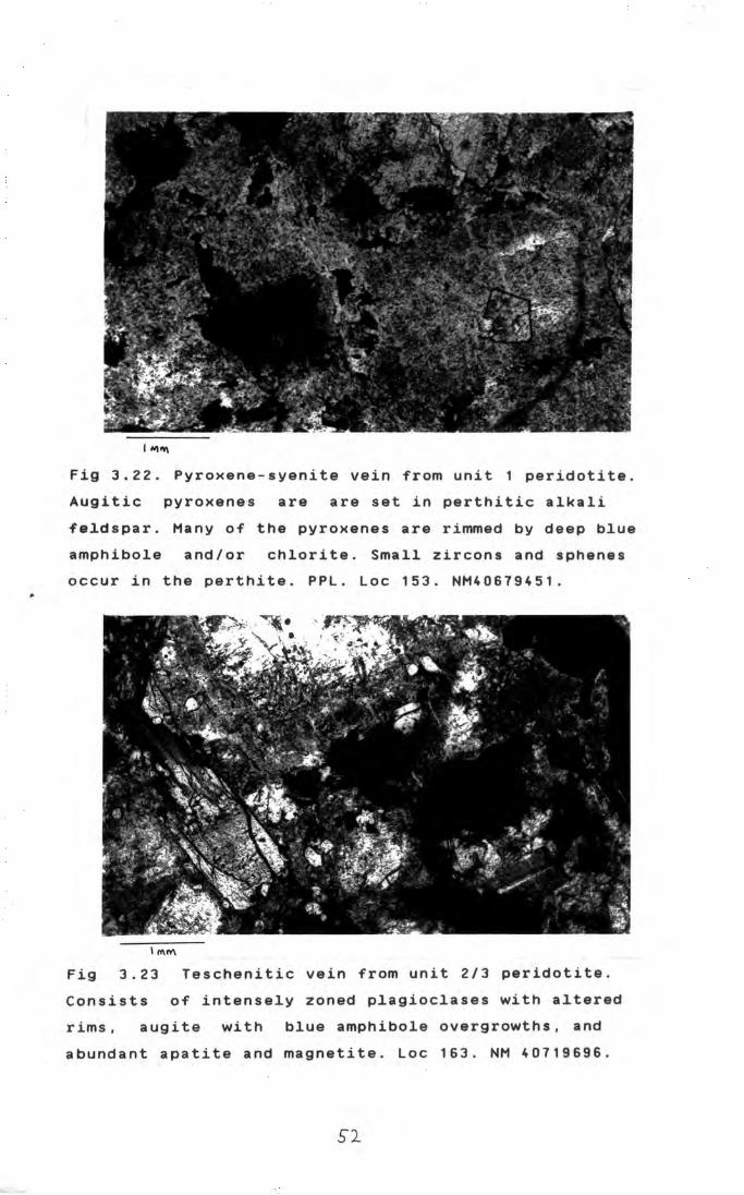
~~~
Fig 3.22. Pyroxene-syenite vein from unit 1 peridotite.
Augitic pyroxenes are are set in perthitic alkali
feldspar. Many of the pyroxenes are rimmed by deep blue
amphibole and/or chlorite. Small zircons and sphenes
occur in the perthite. PPL. Loc 153. NM40679451.
Fig 3.23 Teschenitic vein from unit 2/3 peridotite.
Consists of intensely zoned plagioclases with altered
rims, augite with blue amphibole overgrowths, and
abundant apatite and magnetite. Loc 163. NM 40719696.
52

Fig 3.24 Composite sulphide bleb from unit 1 peridotite.
Consists of chalcopyrite (c), pentlandite (pn) and
pyrrhotite (po).
U1P2.
Partially uncrossed polars. Sample
l m~
Fig 3.25 Magnetite/sulphide intergrowth between olivine
crystals in unit
polars. Sample U1P3.
peridotite. Partially uncrossed
53

form intercumulus blebs and masses which are locally
large enough to enclose several olivine crystals. I
Sulphides are ~ot seen as inclusions within olivine
crystals (cf Vol~er, 1983) nor are they associated with
chrome-spinel (ci Young, 1984, and Dunham and Wilkinson,
19 8 5) . The mine~alogy is fairly simple: pentlandite,
magnetite, pyrrhotite and a little chalcopyrite. This is
a common assemblage found in many layered basic and
ultrabasic complexes. Pentlandite and pyrrhotite usually
form coarse-textured composite grains (Fig 3.24), or
smaller dispersed blebs intergrown with fine-grained
magnetite, which' may coalesce to form larger masses
poikilitically en~losing magnetite crystals (Fig 3.25).
The largest magnetite/sulphide blebs, which may enclose
many olivine cry~tals, tend to be sulphide-poor at the
margins, with la~ge sulphide aggregates in the central
parts. Ex solution of pentlandite within pyrrhotite
grains is rare (c~ sulphides in unit 1 allivalite).
3.C.2 Peridotit~/allivalite contacts
Several types of ~eridotite/allivalite contact can be I
distinguished in the LELS.
(i) Contacts which are planar and the boundary
between the layers' is sharp, on a grain-size scale. Any
lamination present is parallel or sub-parallel to the
contact. This is t~e most common type of contact.
( ii) Contacts with chrome-spinel seams. Only
one such contact1is seen in the LELS (see 3.8.3). In '
thin section this shows the chrome-spinel layer, and the
peridotite sharply truncating the lamination of the
allivalite (Fig 3.26). A similar relationship was found I
by Young (1984) at :the Unit 11/12 boundary. He ascribed
this to the ther~al erosion of the allivalite by
overlying picritic ~iquid, producing a reaction-crust of
chromite.
(iii) Contacts which have been deformed by I
slumping or loading. In thin section these show mixing
of the two populations of cumulus grains: rounded
olivines and chrome-spinels from the peridotite, and
plagioclase and irregular olivines from the allivalite.

i.;- ·• .. .,. .. a-
'"""' Fig 3.26 Chrome-s ine1 1ayer from the 1ow r part of unit
3. The chrome-spine1 1ayer cuts o~f th 1amination of
the under1ying a1 iva1ite. XP. Loc 182. NM40859621.
Fig 3.27 Mixed pe idotite/a11iva1ite from d formed 1ayer
in unit 2. The 1 rge o1ivines are from the p ridotit
the sma11er one , and the p1agio.clases from the
a11iva1ite. A11 are enc1osed within a c1inopyroxene
oikocryst. XP. Satp1e U2P3.
55
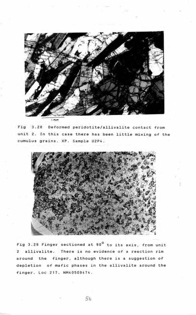
Fig 3.28 Deformed peridotite/allivalite contact from
unit 2 . In this case there has been little mixing of the
cumulus grains. XP. Sample U2P4.
Fig 3.29 Finger sectioned at 90° to its axis, from unit
2 allivalite. There is no evidence of a reaction rim
around the finger, although there is a suggestion of
depletion of mafic phases in the allivalite around the
finger. Loc 217. NM40509474.
Sb
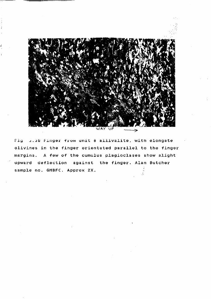
Fiw ~.JO Finger from unit s allivalite, with elongate
olivines in the finger orientated parallel to the finger
margins. A few of the cumulus p!agioclases show slight
upward deflection against the finger. Alan Butcher
sample no. GMBFC. Approx 2X.

In some cases the two populations are well mixed (Fig
3.27), in others mixing is less complete (Fig 3.26). The
degree of mixing often varies considerably, even within
a given layer. This is probably a function of both the
severity of the disturbance causing the mixing, and of
the degree of consolidation of the cumulates.
(iv) Contacts with finger structures. Despite
the evidence from larger-scale field evidence that these
are replacement structures,
are very similar to type
on a microscopic scale they
contacts (Fig 3.29), except
that the peridotite cuts across allivalite lamination.
In a few cases however, a small degree of upward
deflection of plagioclase crystals can be seen adjacent
to the finger. If elongate olivines are present in the
peridotite, these are aligned parallel to the finger
margins (Fig 3.30; see also Butcher et al, 1965). This
implies that the olivines in the peridotite were much
more mobile than the plagioclases in the allivalite, as
the olivines have been capable of being rotated, or
growing from a melt, while the plagioclases have
preserved earlier structures with little deformation.
(v) Contacts gradational on a scale of 10cm -
2m. In the LELS these are mainly found in unit 5. The
main peridotite grades up into the overlying allivalite
over a distance of about 2m. This zone is clinopyroxene
rich peridotite at the base, and olivine-rich allivalite
at the top. The intervening rocks are well layered, the
layering distinguished by variations in the quantities
of olivine + poikilitic clinopyroxene, and cumulus
plagioclase + olivine. The cumulus plagioclases show a
marked
3. 3 1 ) .
normal zoning, with minor oscillations (Fig
The minor peridotite within unit 5 allivalite
has a sharp top, but a gradational base. A section
across the lower contact is shown in Fig 3.32. Abundant
elongate olivines appear in the upper part of the
allivalite, and the amount of cumulus plagioclase
diminishes with height until it disappears, over a
distance of about 0.5m. The olivines in the basal part
of the peridotite are skeletal and elongate, but further

I
\
,-1
I

Fig 3.31 a. Olivine-rich layer from the gradational
contact at the base of unit 5 allivalite. Note presence
of cumulus plagioclase which distinguishes this from
normal peridotites.
b. Plagioclase-rich layer just above 3.31a.
59

Fig 3.32 a Olivine rich allivalite 1.6m below the minor
peridotite within unit 5 allivalite. PPL. Sample USA15.
b Allivalite with elongate olivines from lower
part of gradational contact zone. 1.4m above 3.32a. PPL.
Sample USA16.
c Peridotite from top of gradational contact
zone. 0.2m above 3.32b. PPL. Sample U5A17i.
60

I
up the rounded-granul~r habit becomes dominant.
3.C.3. Allivalites I
The allivaiites I I
are characterised by the
presence of cumulus plagioclase The main minerals are
plagioclase, I
olivine,' clinopyroxene, I
orthopyroxene, and
ilmenite, with lesser: ammounts of phlogopite, zeolites,
clinozoisite, hornblerde, chlorite, sulphides, apatite, I
sphene, and locally q~artz.
3.C.3.a Textures
Plagioclas~ forms >501. of all allivalites I
except locally, in; thin laminae which may consist
largely of clinopyro~ene or olivine.
Plagioclase crystals are often laminated, I
particularly in rocks with little clinopyroxene. Indeed i -
there is a rough inv~rse correlation between the amount
of clihOpyroxene and: the development of lamination. In
individual s pecimen:s lamination is often poorly I
developed, or absen~. where the crystals are enclosed in
clinopyroxene oikodrysts, while outside the oikocrysts I
lamination is pronoJnced (Fig 3.33). This contrasts with
the situation in ;peridotites where lamination is I
unaffected by enclosure (Fig 3.32c). There is also a
tendency for the demsity of plagioclase crystals within
oikocrysts
situation
enclosing
I
to be imuch lower than outside. The same
occurs where olivine forms oikocrysts I
• I plagJ.oclase,
I
In the C1
ase I
although this is much rarer.
of peridotites this low crystal
density was ascribed to post-cumulus textural
( sect:ion3.U) but in allivalites this modification
phenomenon I
occurs 1 in rocks which are clearly not in I
textural equilibr~um, and it occurs regardless of I
whether the oikocryst is clinopyroxene or olivine, I
suggesting that this is not a major factor here. In I I
addition, textural;equilibration in peridotites does not I
affect lamination: of the crystals; thus it is proposed
that both the low/ plagioclase crystal density and the
lack of laminatio~ are early features of allivalites, i
which are preser~ed only where oikocrysts protect them I I
61

-- --- _____ L m"'------
Fig 3.33 Allivalite from unit 5. The plagioclases
enclosed in the clinopyroxene oikocryst are unlaminated,
while those outside display good lamination. XP. Loc
14b. NM39589721.
Fig 3.34 Contact between coarse and fine grained layers
in unit 3 allivalite. The fine grained layer shows a
high degree of textural equilibration. XP. Loc 183.
NM40799620.
62

from the effects o~ later compaction. The cumulus
plagioclase crystals within oikocrysts often do not form
touching crystal frameworks; assuming that the
oikocrysts do not conceal cumulus clinopyroxene cores,
this implies that settling of plagioclase was not a
major factor in producing allivalites.
Some allivalites may have primary lamination.
Where chrome-spinel seams truncate the lamination of
underlying allivalite, the lamination must have
developed at a very early stage, before formation of the
oxide layer.
Sudden changes in plagioclase grain size
define certain types of layering, particularly common in
units and 3 (Fig 3.34). These layers are usually
somewhat lensoid in form. Fine-grained layers have been
described by Thy and Esbensen (1980) from Lille-Kufjord,
and ascribed to fluctuations in the nucleation rate.
However these have since been shown to be flattened
xenoliths (R.S.J. Sparks, pers comm). The LELS layers
show an overlap of grain sizes at the layer boundaries
(Fig 3.34), which might suggest a primary "cumulate"
origin. However texturally they are very similar to
anorthosite xenoliths seen in units 4 and 5 (section
3.C.3.d), including the presence of rare large clustered
plagioclase crystals. It is proposed that these layers
are xenoliths of plagioclase-rich material which was
poorly consolidated when brought to the floor of the
magma chamber, and was flattened during deposition and
compaction. Pyroxene oikocrysts were able to grow across
the xenolith/ cumulate boundary prior to compaction.
3.C.3.b Minor phases in allivalites
Most allivalites contain small quantities of
minerals other than those mentioned above. Phases
recorded include clinozoisite, phlogopite, hornblende,
fibrous zeolites, apatite and sphene. Using
autoradiography of polished slabs, Williams (1978) was
able to detect tiny crystals of zirconolite and
baddelyite in .the mesostasis of LELS rocks, but these
have not been definitely identified in this study.
63

Fig 3.35 Clinozoisite-rich "clot" in allivalite from
unit 3. Other minerals include sphene (s), hornblende
(h), prehnite (p) and chlorite (c). The large grain at
the top left is an orthopyroxene, much altered to
amphibole; at the top right is a plagioclase crystal.
PPL. Sample U3A2. --- -- -- ------- ---~-- -----~-------- ----------
Fig 3.36 Small dispersed sulphide blebs in unit
allivalite. Partially uncrossed polars. Sample U1A3.
64-

Clinozoisite is not uncommon as small patches
occupying the interstices between plagioclase crystals.
However, locally it forms larger "clots" up to 7mm in
diameter, intergrown'with hornblende, prehnite, sphene,
phlogopite and apatite. An as-yet-unidentified brown
mineral is common as tiny radiating masses with high
birefringence in the interstices between clinozoisite
crystals (Fig 3.35). These assemblages occur in rocks
containing fresh ol~vine, although adjacent to the
larger clots olivine is often altered to fine grained
talc(?), chlorite or phlogopite. Against these larger
clots plagioclase may be slightly sericitised, and may
be partially replaced by clinozoisite, although the
smaller patches do not appear to be associated with any
alteration.
There is some evidence from the Marginal Suite
(Fig 2.9) and from alkaline veins in the peridotites
near the Long Loch, that clinozoisite may be on the
liquidus of certain magmas in the Rhum complex. It is
suggested that these clot assemblages are related to
local late-stage enrichment in water, and that they
crystallised, at least in part, from a melt, rather than
forming from previously existing minerals. It is
difficult to see how they could be produced by pervasive
or channelled hydrous alteration of the cumulates, given
the lack of localisation along fractures, and the close
association with fresh olivine and plagioclase. These
clots are particularly common in the middle parts of
unit 4 allivalite, and in unit 3 allivalite.
Allivalite~ within a few metres of the
marginal suite somtimes have small quantities of a
granophyric mesostasis.
3.C.3.c Sulphide minerals
The allivalite of unit 1, like the peridotite,
is remarkably rich i~ sulphide blebs. In the basal parts
of the allivalite they may form up to 5Z of the rock,
and the blebs may rea;ch 1 em in diameter. The mineralogy
is similar to peri:dotite assemblage, except that
chalcopyrite forms a: larger proportion of the blebs in
65

I
t (
------~----- ----------
~ "' \.
,. I'
...,·
'
--~-- -1
I ~
--------------
Fig 3.37 Exolution ,lamellae of pentlandite in large
pyrrhotite grain from unit 1 allivalite. Note large,
early formed "flame" lamellae, and later, finer and more
regular lamellae. Partially uncrossed polars. Loc 152a.
NM40649452.
Fig 3.38 Composite s4lphide bleb from unit 1 allivalite,
consisting of pyrrhotite (po) with pentlandite
exolution, chalcopyrite (ch), pentlandite (pn),
mackinawite (mkl and :cubanite (cbl. The bleb is rimmed
by a fine-grained magnetite/sulphide intergrowth. PPL in
oil. Loc 152a. NM40649452.
66
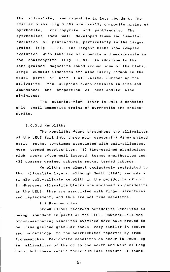
the allivalite, and magnetite is less abundant. The
smaller blebs (Fig 3.36) are usually composite grains of
pyrrhotite, chalcopyrite and pentlandite. The
pyrrhotites show well developed flame and lamellar
exolution of pentlandite, particularly in the larger
grains (Fig 3.37). The largest blebs show complex
exolution with lamellae of cubanite and mackinawite in
the chalcopyrite (Fig 3.38). In addition to the
fine-grained magnetite found around some of the blebs,
large cumulus ilmenites are also fairly common in the
basal parts of unit 1 allivalite. Further up the
allivalite,
abundance;
diminishes.
the
the
sulphide blebs diminish in size and
proportion of pentlandite also
The sulphide-rich layer in unit 3 contains
only small composite grains of pyrrhotite and chalco
pyrite.
3.C.3.d Xenoliths
The xenoliths found throughout the allivalites
of the LELS fall into three main groups: (1) fine-grained
basic rocks, sometimes associated with calc-silicates,
here termed beerbachites, (2) fine-grained plagioclase
-rich rocks often well layered, termed anorthosites and
(3) coarser grained gabbroic rocks, termed gabbros.
Xenoliths are almost exclusively restricted to
the allivalite layers, although Smith (1985) records a
single calc-silicate xenolith in the peridotite of unit
2. Wherever allivalite blocks are enclosed in peridotite
in the LELS, they are associated with finger structures
and replacement, and thus are not true xenoliths.
(i) Beerbachites
Brown (1956) recorded peridotite xenoliths as
being abundant in parts of the LELS. However, all the
brown-weathering xenoliths examined here have proved to
be fine-grained granular rocks, very similar in texure
and mineralogy to the beerbachites reported by from
Ardnamurchan. Peridotite xenoliths do occur in Rhum, eg
in allivalites of'the CS to the north and west of Long
Loch, but these retain their cumulate texture (!.Young,
67

Fig 3.39 Beerbachi~e xenolith from unit 5, consisting of
plagioclase, olivine and clinopyroxene. XP. NM 40199499.
Fig 3.40 Beerbachite xenolith from unit 4 with "clots"
of calc-silicate minerals (c), rimmed by fassaite (f).
Natural light. Loc 176a.

pers comm). A typical beerbachite is shown in Fig 3.39.
They consist mainly of equal-sized polygonal grains of
plagioclase, olivine, clinopyroxene, magnetite, and
often orthopyroxene. Most inter-grain angles are about
1200. regardless of the phases involved, but
clinopyroxene occasionally forms sub-poikilitic grains,
or rims around other phases. A faint lamination is often
evident. This has probably developed during recrystall-
isation, as parallel planar structures are absent in
these rocks. A few lbeerbachites contain larger porphyro
blasts of plagioqlase or olivine. Irregular veins of
clinopyroxene or fine-grained plagioclase are common.
The latter particularly, are often associated with clots
rich in calc-silicates. These are invariably zoned with
an outer zone of fassaite, and a core of intergrown
garnet, diopside, sometimes plagioclase, and small
quantities of vermiculite (Fig 3.40). Where the fassaite
adjoins the beerbachite, there is often a zone of
intergrown magnetit,e blebs (Fig 3. 41). Across this zone
the optical propert~es of the pyroxene changes, a yellow
tint becoming incrEasingly intense towards the core of
the clot, and associated with this, an increase in the
dispersion. The innermost fassaites show intense
anomalous blue interference colours. A few of these
clots contain a little clinozoisite, or low-Fe epidote.
This asspciation of calc-silicates with
fine-grained basic hornfelses strongly suggests that
these rocks were or ig ina.tlj amygda loida 1 basalts, and
thus represent mat~rial derived from the country rocks
of the intrusion. Amygdale assemblages of calcite,
calcium zeolites and celadonite or chlorite would have
roughly the correct chemistry to produce the observed
metamorphic
nowhere seen
minerals. The Rhum ultrabasic complex is
in contact with amygdaloidal basalts;
presumably they formed roof or wall rocks to the upper
part of the magma chamber, since eroded away. This
implies a high-leve~ origin for the ultrabasic complex, I
with the magma chamber in contact with hydrothermally I
altered basalts. Amygdaloidal basalts which pre-date the I
I
ultrabasic rocks are seen in the complex fault zone on
69

the south-east flank of Beinn nan Stac (Smith, 1985).
(iil Anorthosites
The anorthosite xenoliths are usually angular
and well layered and laminated. Mafic minerals are
almost invariably poikilitic in habit, although large
well-formed orthopyroxenes occur in one specimen (fig
3.42). The main mafic silicates are clinopyroxene and
olivine, although the sample with the large
orthopyroxenes contains a thin layer rich in inverted
pigeonite (fig 3.43). Magnetite blebs are locally
common. The layering in these rocks is defined mainly by
changes in the abundance, or types of mafic minerals
present, and to lesser extent, by changes in grain size.
The layering is usually on a 1mm-1cm scale. Some layers
consist of 100t plagioclase. Optical zoning is faint, or
absent in the plagioclases, which are generally
bytownites. A few specimens contain larger, sometimes
glomeroporphyritic plagioclase crystals. These xenoliths
are thus very similar in texture to the lensoid,
fine-grained, plagioclase-rich layers seen in units
and 3. It may be that these layers formed from "soft",
xenoliths of the same material, which was able to deform
during deposition and compaction, wheras the angular
xenoliths of units 4 and 5 represent better consolidated
material.
The strongly layered and laminated aspect of
the anorthosites, together with their mineralogy
suggests that they may be of cumulate origin. However
the grain sizes of both the xenoliths and the
fine-grained layers are very similiar to those of the
beerbachites, and locally, where particularly rich in
mafic minerals, they resemble some of the beerbachites.
Given the high degree of textural equilibration in these
fine-grained rocks, it is difficult to say much about
their origonal textures, however it is unlikely that the
anorthosites represent metamorphosed volcanic rocks in
view of their high plagioclase content. Unlike the
beerbachites the anorthosites are never associated with
calc-silicate minerals, further suggesting a different
origin. A sedimentary origin is also possible; this
70

Fig 3.41 Outer margin of fassaite zone from a ca1c
si1icate c1ot. Note the decrease in pyroxene grain size,
and the exo1ution of magnetite towards the beerbachite.
Loc 20b. NM 39799t15.
Fig 3.42 Large Cqumu1us?) hypersthene crysta1 in fine
grained anorthosite xeno1ith from unit 4. PPL. Loc 194c.
NM40299697.
71
,..-), I
might explain the layering, but again it is hard to
envisage sedimen!ts of the correct bulk composition. A
cumulate origin ~s thus preferred.
It
beerbachites
anorthosites
is tentatively proposed that while.the
r e p:r e s en t the b a s a 1 tic co u n try roc k s . t he
repTesent fine-grained evolved cumulates
formed at the ropf of the intrusion. The abundance of
orthopyroxene may be explained by the ponding of light
magma, contaminated by silicic country rocks at the
walls, under the roof. The development of such a upward
convecting boundary layer would be very likely, if as
has been suggested (chapter 2) the Rhum complex is
largely in situ, and walled by low melting-point arkoses
and granophyres.
The roof rocks, both cumulates and basalts,
were abie to sink. or be carried down to the floor of the
magma chamber trroughout the formation of the LELS
allivalites. Well~consolidated cumulate material is most
abundant in units 4 and 5, where the greatest abundance
of beerbachite is found, suggesting that considerable
quantities of roof rocks were dislodged during the
formation of thes~ units.
(iii) Gabbros
The gabbro xenoliths are coarser than the
others, and their· textures are very similar to those of
the rocks in which they are enclosed (Fig 3.44). They
are extremely abundant in parts of unit 5 allivalite, of
which they may form >501.. They are characterised in thin
section by intense clouding of mafic phases by exsolved
magnetite. Many specimens are rich in poikilitic
orthopyroxene. As well as cumulate textured gabbros,
rocks with sub-variolitic textures are also found.
3.C.4 Gabbro plugs and sheets
The main minerals are clinopyroxene and
plagioclase. The former is usually pale brown with
marked normal zon~ng. Sector zoning is occasionally well
developed. Habit yaries from euhedral prisms to ophitic
intergrowths with plagioclase. The latter forms narrow '
laths, generally: showing strong continuous normal
72

Fig 3.43 Inverted pigeonite oikocryst in anorthosite
xenolith from unit 4. XP. Loc 194c. NM40299697.
Fig 3.44 Gabbro xenolith from unit 5 allivalite showing
intense clouding of clinopyroxene, and to a lesser
extent, of plagioclase. Loc 20c. NM 39799715.
73

zoning. Other minerals present are Fe-Ti oxides, as
large irregular grains; olivine, usually as large
altered grains, and green amphibole. A fine-grained
mesostasis is often present, usually altered to
chlorite; this is one of the best features for
distinguishing the gabbros from the clinopyroxene-rich
allivalites.
3.0 Conclusions
(1) The morphology and distribution of the
allivalite and peridotite layers of the LELS have been
affected by a number of post-cumulus processes including
deformation of poorly consolidated crystal mushes, and
later, by replacement of allivalite by peridotite.
(2) The allivalite horizons contain varying
quantities of xenolithic material derived from the walls
or roof of the magma chamber, including amygdaloidal
basalts, which are not now seen as country rocks. This
implies a high-level for the magma chamber, not far from
its present position.
(3) The layers richest in roof-or wall-derived
xenoliths are also richest in orthopyroxene, as are the
cumulates seen in these xenolith assemblages. This may
suggest ponding of silica rich magmas at the top of the
chamber.
(4) There is evidence that some peridotite
layers may have been more mobile and permeable than
overlying allivalites.
(5) Crystal settling may have been a
significant process in the formation of peridotites, but
other than the presence of xenoliths, there is no
unambiguous evidence in the LELS allivalites for
settling being important.
(6) The textures of the cumulates are affected
to varying degrees by post-cumulus processes, some of
which may be sub-solidus. Most LELS rocks are not in
textural equilibrium. Lamination may be a primary
feature of olivines in peridotites, but lamination of
plagioclase in allivalites mostly originates during
compaction. This is not always the case though. Where

lamination is truncated by chrome-spinel seams (unit 3,
unit 11/12) la~ination must be a very early feature,
probably primary.
75
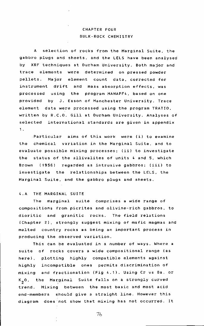
CHAPTER FOUR
BULK-ROCK CHEMISTRY
A selection of rocks from the Marginal Suite, the
gabbro plugs and sheets, and the LELS have been analysed
by XRF techniques at Durham University. Both major and
trace elements were determined on pressed powder
pellets. Major element count data, corrected for
instrument drift and mass absorption effects, was
processed using the program MANAPF4, based on one
provided by J. Esson of Manchester University. Trace
element data were processed using the program TRATIO,
written by R.C.O. Gill at Durham University. Analyses of
selected international standards are given in appendix
1 •
Particular aims of this work were (i) to examine
the chemical variation in the Marginal Suite, and to
evaluate possible mixing processes; (ii) to investigate
the status of the allivalites of units 4 and 5, which
Brown ( 19 56) regarded as intrusive gabbros; (iii) to
investigate the relationships between the LELS, the
Marginal Suite, and the gabbro plugs and sheets.
4.A THE MARGINAL SUITE
The marginal suite comprises a wide range of
compositions from picrites and olivine-rich gabbros, to
dioritic and granitic rocks. The field relations
(Chapter 2), strongly suggest mixing of mafic magmas and
melted country rocks as being an important process in
producing the observed variation.
This can be evaluated in a number of ways. Where a
suite of rocks covers a wide compositional range (as
here), plotting highly compatible elements against
highly incompatible ones permits discrimination of
mixing and fractionation (Fig 4.1). Using Cr vs Ba. or
the Ma~ginal Suite falls on a strongly curved
trend. Mixing between the most basic and most acid
end-members should give a straight line. However this
diagram does ·not show that mixing has not occurred. It
76

0 (\J
~
1250
1000
750
500
(;3250
0
0
6
66
6 6 + 6
6
250 CR
Fig 4.1a Ba vs
+
+
500 750 1000
Cr plot for the Marginal Suite
(triangles), and the gabbro plugs and sheets (crosses).
8 +
6
4
2 6
66
6 6 6 6 .6
66 6 6 6
+ + 6 6 6 6
0 t + + 6 6
0 250 500 750 1000 CR
Fig 4.1b Cr vs K2
0 plot for the Marginal Suite and the
gabbro' plugs and sheets. Symbols as above.
77

does illustrate that most of the intermediate rocks have
not been produced by mixing picritic rocks and felsite
or sediments, but cannot rule out mixing between low-er
basic rocks and acid melts. It is noteworthy that
several of the basic samples do show slightly enhanced
Ba and suggesting that small ammounts of
contamination may have occurred.
Another method for distinguishing fractionation and
mixing in tholeiitic sequences has been used by Marshall
and Sparks (19S4). Ti and Pare strongly enriched in
intermediate tholeiitic fractionates, while mixing
low-Ti,P acid rocks and low-Ti,P basic rocks can only
produce low-Ti,P intermediate hybrids. The Marginal
Suite shows both trends (Fig 4.2), indicating that some
of the diorites are hybrids, while a few are
fractionates. The maximum Ti02
and P2o
5 contents occur
at about 77. MgO; this is higher than the value in other
tholeiitic suites where it is usually about 4-51. (see
for example Marshall and Sparks, 1984) However the number
of samples on the fractionation trend is relatively
small and cannot be regarded as a complete sample.
To quantify mixing processes, it is essential to
identify the correct end-members. Although picrites
occur in the Marginal Suite, they do not seem to have
mixed with acid material on a large scale (see above).
The only
enhanced
evidence of contamination in these rocks is
incompatible trace elements. Fig 4.2 suggests
that more fractionated gabbros (about 101. MgO) may be
the usual basic end member, as this is the value at
which the mixing and fractionation trends diverge.
Picritic liquids may not mix readily with acid melts for
several reasons. There is likely to be a considerable
viscosity difference, even if the acid melts are locally
superheated, and this inhibits mixing (Campbell and
Turner, 1986). High density contrasts would also
decrease the tendency to mix, and the great difference
in liquidus t~mperatures between picrite and granite may
result
occur.
in quenching of the picrite before mixing could
Thus it appears that hot picritic liquids were
not prone to mixing with acid melts; only cooler, less
78

lf)
0 (\J Q_
(\J 0
1-
0. 4
0.3 6
6
6
0.2
6
6
0. 1 6
6
6
0. 0
0
Fig 4.2a
(triangles)
3
+ 6
6
+
6 6 + +
6 +
6 6+ 6
66 6 6
6 6 6 6 6
+ 6 6
6
5 10 15 20 25 MGO
MgO vs P2o
5 plot for the Marginal Suite
and the gabbro plugs and sheets (crosses).
+ 6
6 6
2
~ +
6 +
6 6
6 + 66 +
tr,6
6 6 e. 6 6
6
666
6
0
0 5 10 15 20 25 MGO
Fig 4.2 b MgO vs Ti02
plot for the Marginal Suite and
gabbro plugs and sheets. Symbols as above.
79
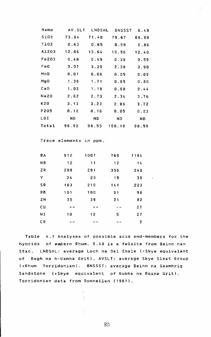
Name
Si02
Ti02
Al203
Fe203
FeO
MnO
MgO
CaO
Na20
K20
P205
LOI
Total
AV.SLT
73.64
0.63
12.86
0 .. 4 6
3.07
0. 01
1 . 3 6
1 . 0 2
2.62
3. 13
0. 1 2
NO
98.92
LNDSHL
7 1 . 4 0
0.65
13.64
0.49
3.29
0.06
1 . 7 1
1 . 1 8
2.73
3.23
0. 1 6
ND
98.55
Trace elements in ppm.
BA
NB
ZR
y
SR
RB
ZN
cu
NI
CR
912
1 2
299
24
183
1 0 1
35
1 0
1007
1 1
291
23
210
1 0 0
39
1 2
BNSSST
79.67
0.59
10.56
0.36
2.38
0.05
0.65
0.68
2.34
2.86
0.05
NO
100.19
769
1 2
356
1 9
1 4 1
9 1
2 1
5
6.48
69.80
0.86
1 2. 4 0
0.59
3.90
0.09
0.80
2.44
3.76
3.72
0.23
NO
98.59
1 1 8 4
1 4
240
39
223
96
82
27
27
2
Table 4.1 Analyses of possible acid end-members for the
hybrids of e~tern Rhum. 6.48 is a felsite from Beinn nan
Stac. LNDSHL: average Loch na Dal Shale (=Skye equivalent
of Bagh na h-Uamha Grit). AVSLT: average Skye Sleat Group
(=Rhum Torridonian). BNSSST: average Beinn na Seamhrig
Sandstone (=Skye equivalent of Rubha na Raine Grit).
Torridonian data from Donnellan (1981 ).
so
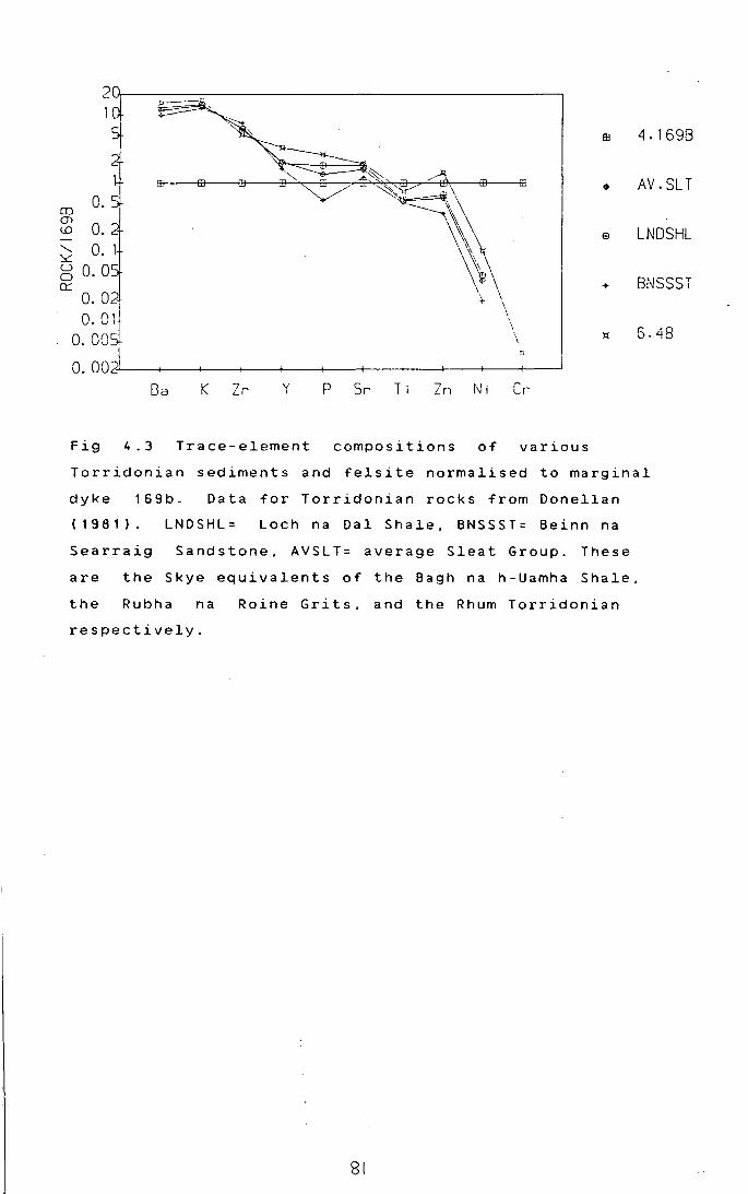
~~~~~------------------, I
m 4.1698
EB • AV.SLT m 0. CJ) \.{) m LNDSHL ........ 0. 1 ::.:::: (_) 0. 0 0 0::: + BNSSST
~ 6. 48
Ba K Zr y P Sr Ti Zn N i Cr
Fig 4.3 Trace-element compositions of various
Torridonian sediments and felsite normalised to marginal
dyke 169b. Data for Torridonian rocks from Donellan
(1981). LNDSHL= Loch na Dal Shale. BNSSST= Beinn na
Searraig Sandstone. AVSLT= average Sleat Group. These
are the Skye equivalents of the Bagh na h-Uamha Shale,
the Rubha na
respectively.
Raine Grits. and the Rhum Torridonian
81

dense and more vi~cous basic liquids would mix.
Identificatipn of the acid components is more
difficult. Possibilities include Rubh na Raine Grit,
Bagh na h-Uamha ~hale, and felsite. Detailed chemical
data on the To~ridonian rocks of Rhum is lacking.
However extensiv~ data for the laterally equivalent
rocks in Skye is available (Oonellan. 1981), and his
average values for these units are used in this study.
Comparison of these analyses with limited unpublished
data for the Rhum. Torridonian CR. Greenwood, pers comm)
shows good agre~ment. In the western part of the
complex, granophyre is likely to be a major contaminant.
Unfortunately the major-element chemistry of these
groups is remarkably similar (Table 4.1). In an attempt
to resolve this, ~odified "spidergrams" for the various
possible contaminants, normalised to one of the Marginal
Suite gabbros, are shown in Fig 4.3. The patterns for I
the hybrids are'shown in Fig 4.4. Assuming that the I
normalising rock'is close to the basic end-member, the
hybrids should show patterns parallel to the acid
end-member with which they mixed. The patterns for the
contaminants are very similar, except for Zn and P,
which are > in the felsite, and are < 1 in the
Torridonian rocks;
The patterns for the hybrids in most cases are ' consistent with mixing with these components, although
the marked deplet~on in Ni and Cr. together with -ve Sr
anomalies, sugge.ts fractionation combined with mixing
for many rocks. The role of felsite and Torridonian I
rocks is difficuli to distinguish. High P hybrids could I
be explained by f~lsite contamination; but P also tends
to increase with ~ractionation, so this is not a useful
discriminant. Zn does not show much change with
fractionation in the gabbro plugs and sheets (Fig 4.5),
and thus it ma~ be a better guide to contaminants.
Hybrids with Zn markedly greater than 1 on Fig 4.4 must
have been conta~inated by a high Zn material, ie
felsite. Low Zn hibrids may be Torridonian-contaminated.
Palacz( 1984) ,; and Palacz and Tait I 1985). using Pb
and Sr isotopes, :argued that the Rhum ultrabasic magma
S1

CD (})
(() 0. '~
g 0.0 0:::
0. 02 0.01
0.00
fD
0.002L--+---r--+---~-+---r--+---~-+--4-~
Ba K Zr y P Sr T i Zn N i Cr
2 B
CD (})
0. (()
........ 0. 1 ~ u 0.0 0
.0:::
0. 01 0.00'
0.002 Ba K Zr y p Sr Ti Zn Ni Cr
EB
~
m
+
:lt
6
... v
0
0
EB
<>
m
+
:lt
6
9
v
0
0
Fig 4.4 a,b Trace element compositions of the Marginal
Suite normalised to marginal dyke 169b. 4.4b includes
many of the Marginal Suite rocks showing evidence for
fractionation.
83
4.1698
5.78
5.10
5.11
5.15
5.32A
5.328
5.36
5.39
5.41
4.1698
5.428
5.42C
5.45
5.46A1
5.46A2
5.46C
5.80A
5.80C
5.1658

chamber was walled by Lewisian amphibolite-facies
rocks, and had since been emplaced upwards along faults.
However, if has has been argued in Chapter 2, the
complex is largely in situ, it is difficult to see how
liquids residing in the chamber become contaminated with
such rocks. However, their data (Fig 1, Palacz and Tait,
1985) do not exclude contamination by rocks of similar
isotopic compositions to the Skye acid intrusives.
Recent work by R. Greenwood (pers comm) on the Sr and Pb
isotopes of Rhum felsites, indicates that they fit these
requirements well. Thus evidence in the Marginal Suite
for contamination by felsites fits in well with the
isotopic evidence for such contamination in the main
body of the magma chamber. The new isotopic evidence
also supports the idea of a high-level, in situ origin
for the ultrabasic complex, walled in part by earlier
Tertiary acid rocks, rather than a tectonically emplaced
chamber which evolved at depth enclosed by Lewisian
rocks.
4.B GABBRO PLUGS AND SHEETS
Most of these bodies are mineralogically and
petrographically similar (section 3.C.4), and thus it
would seem reasonable to propose that they are also
chemically related. Indeed, on Figs 4.2a and 4.2b, they
fall roughly on the Marginal Suite fractionation trend.
It is possible to model the major element chemistry
of these rocks by subtracting magnesian olivine,
plagioclase and diopsidic clinopyroxene from rock 53A,
the quenched marginal picrite . However there
is not a perfect correlation between the quantities of
these phases which have to be removed; thus the evidence
is somewhat ambiguous.
Trace element data (Fig 4.6) do not support
extensive plagioclase fractionation, as there is no -ve
Sr anomaly developed. However, they support the idea of
marked olivine fractionation, and perhaps a little
clinopyroxene. Sample 53A shows the expected tra~e
element pattern for a high-Mg parent to the gabbros,
except for Ba and K which are markedly enriched. This is

100
80 6
60
40 6 6
z 20 6
N 6
0
0
6 6
6
6 + 6
6 666
~ 6
5 MGO
6
+
6 + 6 6 6 + +
+ M
+ It
10 15 20 25
Fig 4.5 MgO vs Zn plot for the Marginal Suite and gabbro
plugs and sheets .
........ !B c '10 .L:
~
'-(L ....... ~ EB
0 0 0.
0:::
0. +
0. 1 ~
0.0
0.02 6
Ba K Zr y p Sr Ti Zn Ni Cr ?
Fig 4.6 Trace element compositions of gabbro plugs and
sheets normalised to primordial mantle (Taylor and
McClennan, 1985).
85
4.98
4.1698
4.175A
4.181
4.201
4.202
5.53A

almost certainly due to slight contamination by melted
country rocks. (see previous section). Ni falls off much
faster than Cr in the rocks showing slight Ni and Cr
depletion, presumably because the crystallising
assemblage was rich in olivine. However the most evolved
rocks (lowest Ni and Cr), show relative depletion in Cr.
suggesting that Cr-rich phases such as clinopyroxene, or
perhaps oxides, had become liquidus phases.
A curious feature shown by these gabbros is the
apparent lack of Zr enrichment with fractionation,
suggesting that the crystallising assemblages had bulk
distribution coefficients of about 1 for Zr.
4.C THE LAYERED ROCKS
As the rocks of the LELS are cumulates, and the
compositions are controlled by the relative proportions
of three main minerals (Fig 4.7), whole rock analyses
are of little use ~n examining trends in the liquids
from which they crystallised. Interpretation is further
complicated by evidence for migration of intercumulus
liquids, for example the instability of intercumulus
orthopyroxene in peridotites, and the replacement of
allivalite by peridotite. (see chapters 5 and 6). This
implies that intercumulus assemblages need not be
fractionates of the same liquids which formed the
cumulus crystals in a given rock. Thus concentrations of
incompatible elements need not be related to retention
of melt in equilibrium with the cumulus phases.
Despite these problems, it is possible to use the
whole-rock data to assist in classifying the xenolithic
layers in units 4 and 5. Brown (1956) argued that they
were intrusive gabbros, whereas the present work has
cast doubt on this (chapter 3). In terms of their
chemistry they seem to be related to the cumulates,
rather than the clearly intrusive gabbro plugs and
sheets. This is
hypothesis more
shown in
rigorously,
Fig 4.8. To test this oF
the analyses1
these three
groups of rocks were analysed using cluster analysis.
4.C.1 Cluster Analysis
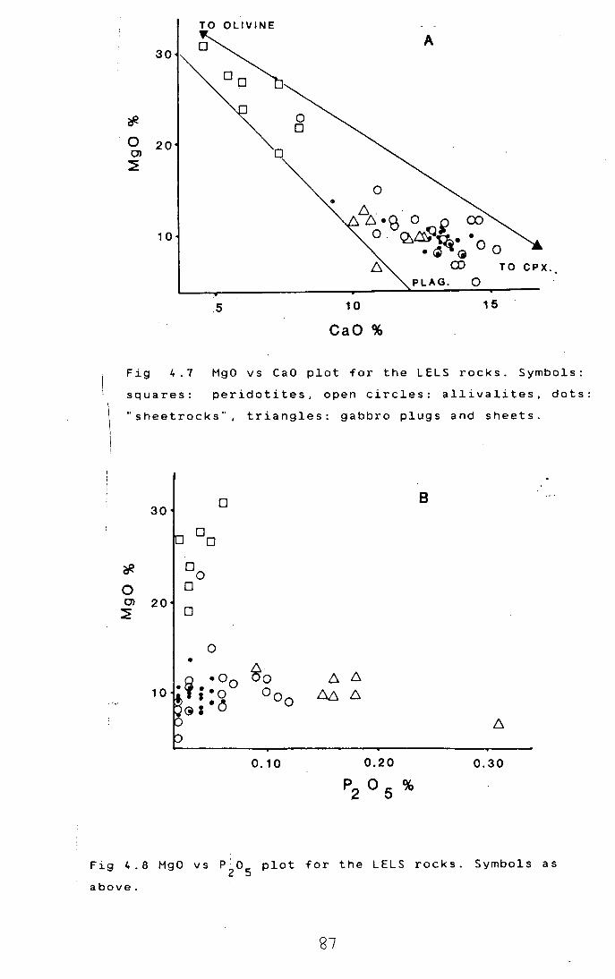
TO OLIVINE
~ A
30
?f. 0 0
0 20 C) 0 ~
0
!:::. . . 6 ·g 0 ~ (X)
10 0. ~~Ft·. • ~ (j 0 0
~ CD TO CPX.
PLAG. 0
.5 10 15
·cao%
Fig 4.7 Mgd vs CaO plot for the LELS rocks. Symbols:
squares: peridotites, open circles: allivalites. dots:
"sheetrocks", triangles: gabbro plugs and sheets.
0 8 30
0 0
* oo 0 0 C) 20
:E 0
0 • fj •Oo Bo 6 6
10 • • • Oo 1::0:. 6 ··8 <il 0
0.10 0.30
Fig 4.8 MgO vs P~o 5 plot for the LELS rocks. Symbols as
above.
87
OVERLEAF Fig 4.9 Dendrogram for the LELS allivalites,
"sheetrocks", and gabbro plugs and sheets. Sample
numbers are shown down the left hand side of the
diagram. Prefixes to sample numbers indicate the group
to which they belpng: 2=allivalites, 3=sheetrocks,
4=gabbro plugs and sheets.
88

4.98
2.111
4.93A 4.1698
3.11A 2.938 4.181
4. 201
4.202 2. 165C
4. 175A 2.89
3.12 3.18
3.200 3.150
3.17901 3.17902
3 .13A
3.123
2. 1948 2. 1q4F
3.178 3.194A1
3.118 3.20(
3.132
3.135
3.139 3. 194A2
3.14A
3.148
2.87 3.24
2.37 2.89
2.173 2.861
2.862
2.90
2.21 2.1958
2.19SC 2.194(
2.19401 2.19402
3. 141 2. 91
2.1648
·-------------------·----------------------------------------------------1 ·-------------------------------------------------------------------------1-------1 •---------------------------------------------------1 I • ---------------------------------------------------1-----------------1 ·-----------------------------------1 1-------1 ·---------------------"-------------1---------------------------------1 1---1-------1 ·-----------------------------1 1---1 •-----------------------------1---------------------------1-------1 I ·---------------------------------------------------------I 1-----------1 • ... - .......... - ............ - .............................................. - -- ................................................................................................. I
·-------------·---------------------------------·-·---------------------·--·----------1
1-1 I
I I I I I I
• ---------- ----------- ----- .. --------------------------------------- ................. ---------- ....................... --1 • ----------- - --------------------·-----1 ·------------ ---------------------------1-----1 ·-------------1 1---------1 ·-------------1-------------------------------1 1-----1 •---------1 I I
•---------1---------------------------------------------1 I • -------------------------I +-----------------------1 I ·---------------------1 1-1-----------------1 •---------------------.1-1 I 1-1 ·-----------1 I 1-----------1 ·-----------1---------------1---------1 I I
•---------------------------1 I 1----------------1 •-------1 I ·---1 1---------1 1-----1 1-------1 ·---1---1 1-------------------1 ·-----1 ·-----1-----------1 ·---------------1
1-----1-1
• ---------------1-------------------------------1---------------1 ·---------------- ...... ----------·------------------1 •--- .................................................................... I
·-------------------------------1---------------------1 ·-----------------------------------------1 1-----------------1 • -----------------------------------------1-----------1 1---1 • -------------------I ·-----------~-------1--------------------------------------1-----------1 • ------------------------------------ .................. -----------------1 ·-----------------------------------------------·-------------------1 ·-------~-------- ---------------------------------1 1-----------1 • --------------------------------" ----------------1-----------------1 I I ·---------------------------------1 1---I •-1 1---------------------------------------------l •-1-------------------------------1
I 1---1 I I I I I I I I I I I I
I
I I I I I I I I I I I I I
+ ---------------------------------------------------------------------------------- -------I I •---------------------------------------------------------------------------------------I I • ---------------------------------------------------------------------------------------1---1
.. 11111 112233333 45556667891 111122233455677123 15.. ...••. • ..•. 1 145923715326717808 5505567899173478811001125678. . ...•....... 691
717076197771816092204580440804837159894462855 •.•
688934540592853590&&4754480942&71700523920517959
N 897979285737563383956004422095629011954244242585
c

Cluster analysis is a multivariate statistical
technique for classifying unknown objects. It makes no
assumptions about the data. and seeks to determine any
natural groupings or clusters of the data in
mul tid imen sional s pa.ce. A good simple review of the
technique can be found in Le Maitre (1982).
The results of cluster analysis obtained on
analyses of allivalites, "sheetrocks". and clearly
intrusive gabbro plugs and sheets is shown in Fig 4.9.
This was performed using the MIDAS statistical package
on the Durham University mainframe computer.
Cluster analysis first involves the calculation of
a "similarity measure" between evey object in the data
set. This can be calculated in a nmber of ways, but the
method used here is Euclidean distance, calculated as
follows:
where .th
J
Dij = c~~k-xjk> Xik and Xjk are the k variables of the ith and
objects respec.tively. and p is the nomber of
variables. D .. is 0 for identical objects and becomes ~J
bigger with increasing dissimilarity. To avoid problems
with the combination of 1. and ppm data used here. the
data has been standardised, with equal weight given to
all variables.
Having obtained a similiarity matrix by the above
procedure, the objects can be linked together to form
clusters or groups by increasing the distance
incrementally such that two objects or clusters combine
at each step to form a new cluster. Thus at a distance
of 0, all the objects are distinct, but at a distance of
382 all the rock• fall into one cluster. There are
various methods for linking objects and clusters; the
one used here is. complete-linkage. This combines
clusters on the basis of minimising the maximum distance
between objects in two clusters. It is customary to
represent this clustering behaviour on a dendrogram.
Looking at Fig 4.9, it can be seen that the
allivalites and sheetrocks all fall inside a common
cluster at a distance of 77. The gabbro cluster does not
merge with them until a distance of 381. These are the
90

NE -----------------+------------~~
HY
Fig 4.10 Normative: compositions of LELS rocks and • • I • • •
alkal~ne ve~n from u?~t 3 per~dot~te. Symbols: crosses =
peridotites, up-pointing triangles = allivalites, down-1
pointing triangles ~ "sheetrocks", circle with cross = !
alkaline vein, square = marginal picrite 53A.
91
!
I
two main clusters i~ the dataset. Within the allivalite/ I
sheetrock cluster, ! the two groups can also be
d . t. . I 1s 1ngu1shed although many of the allivalites are more
similar to the s~eetrocks than they are to other
allivalites.
I 4.C.2 Norms o~ LELS rocks
CIPW norms wJre calculated using an assumed
Fe 3 + I Fe 2 + ratio of o!. 1 5 ( Brooks , 1 9 7 6 ) . Most of the L E L S
rocks are olivine an~ hypersthene normative with no free
quartz and thus ar~ broadly tholeiitic. However the
a 1 k a 1 in e v e in fro ml U n i t 3 per i d o t it e ( S amp 1 e 1 6 3 ) i s
nepheline normative (Fig 4.10). This rock is also
notably rich in P2o
5 and Ti0
2 (Appendix 2).
I
4.0 CONCLUSIONS I
(i) The Marginal Suite shows evidence for mixing !
with both Torridonian sediments, and felsite. However I
many rocks also s~ow signs of being fractionates.
Although picritic rocks occur in the Marginal Suite, and I
are contaminated, particularly with regard to Ba and K, I
the intermediate rocks have mostly been produced by . I
mixing of more evolved gabbros with melted country I
rocks. I
(ii) Most of thJ LELS rocks are olivine-hypersthene I
normative, a 1 though • late fraction a ted veins in
peridotites may be nJpheline normative.
(iii) The fine~grained, xenolithic layers in the
allivalites of unit~ 4 and 5 are chemically similar to
the other LELS alliJalites. They are distinct from the I
clearly-intrusive ga~bros. While this does not disprove
an intrusive origin ,I taken together with the field and
petrographic evidencel, it supports their being regarded
as part of the layere~ series.
I
92
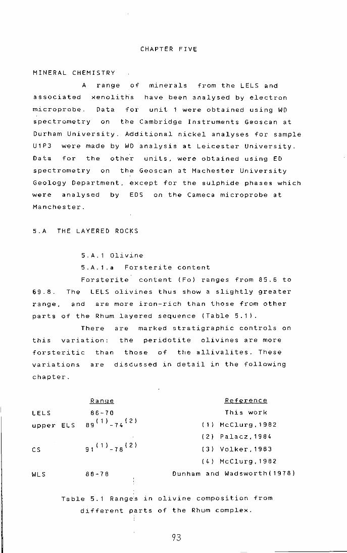
CHAPTER FIVE
MINERAL CHEMISTRY
A range of minerals from the LELS and
associated xenolitHs have been analysed by electron
unit 1 were obtained using WD microprobe.
spectrometry
Data
on
for
the Cambridge Instruments Geoscan at
Durham University. ~dditional nickel analyses for sample
U1P3 were made by WD analysis at Leicester University.
Data for the other units, were obtained using ED
spectrometry on the Geoscan at Machester University
Geology Department, except for the sulphide phases which
were analysed by EDS on the Cameca microprobe at
Manchester.
5.A THE LAYERED ROCKS
69.8.
range,
5.A.1 Olivine
5. A. 1 . a Forsterite content
Forsterite content (Fo) ranges from 85.6 to
The
and
LELS olivines thus show a slightly greater
are more iron-rich than those from other
parts of the Rhum layered sequence (Table 5.1).
There are marked stratigraphic controls on
this variation: the peridotite olivines are more
forsteritic than those of the allivalites. These
variations are discussed in detail in the following
chapter.
Range Reference
LELS 86-70 This work
upper ELS 8 9 ( 1 ) - 7 4 ( 2 ) ( 1 ) McClurg, 1982
( 2) Palacz,1984
cs 9 1 ( 1 ) - 7 8 ( 2 ) ( 3) Volker, 1983
( 4 ) McClurg, 1982
WLS 88-78 Dunham and Wadsworth(1978)
Table 5.1 Range:s in olivine composition from
different parts of the Rhum complex.
93
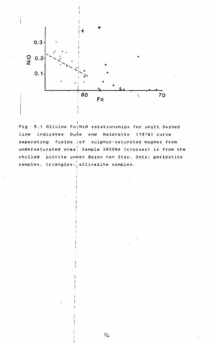
I I i I ,+ +
I' 0.3 I
I
..... I 0 0.2 .... . I • ........ z ......
! ...... " .. ......... • I
........ .. 0.1 I' ..
I ~ 6
6 .. .. 80 '• 70
Fo
Fig 5.1 Olivine Fa NiO relationships for unitt. Dashed
and Naldretts (1978) curve line indicates oure
separating fields lof sulphur-saturated magmas from
undersaturated ones~ Sample SR209A (crosses) is from the . I
chilled picrite un~er .Beinn nan Stac. Dots: peridotite . I . .
samples, tr~angles: 1 all~val~te samples.
I 1.
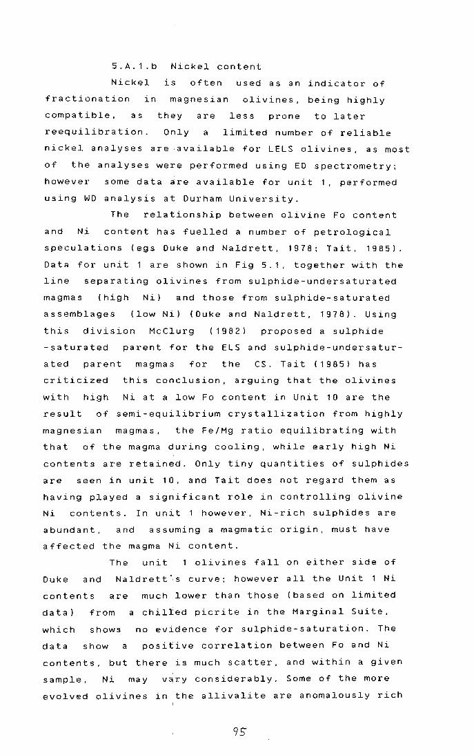
5. A. 1 . b Nickel content
Nickel
fractionation in
compatible, as
reequilibration.
is often used as an indicator of
magnesian olivines, being highly
they are less prone to later
Only a limited number of reliable
nickel analyses are .available for LELS olivines, as most
of the analyses were performed using ED spectrometry;
however some data ~re available for unit 1, performed
using WD analysis at Durham University.
The relationship between olivine Fo content
and Ni content has fuelled a number of petrological
speculations (egs Duke and Naldrett, 1978; Tait, 1985).
Data for unit 1 are shown in Fig 5.1, together with the
line separating olivines from sulphide-undersaturated
magmas (high Nil and those from sulphide-saturated
assemblages (low Nil (Duke and Naldrett, 1978). Using
this division McClurg (1982) proposed a sulphide
-saturated
ated parent
criticized
with high
parent for the ELS and sulphide-undersatur
magmas for the CS. Tait (1985) has
this conclusion, arguing that the olivines
Ni at a low Fo content in Unit 10 are the
result of semi-equilibrium crystallization from highly
magnesian magmas, the Fe/Mg ratio equilibrating with
that of the magma during cooling, while early high Ni
contents are retained. Only tiny quantities of sulphides
are seen in unit 10, and Tait does not regard them as
having played a significant role in controlling olivine
Ni contents. In unit 1 however, Ni-rich sulphides are
abundant, and assuming a magmatic origin, must have
affected the magma Ni content.
The unit olivines fall on either side of
Duke and Naldrett ',s curve; however all the Unit 1 Ni
contents are much lower than those (based on limited
datal from a chilled picrite in the Marginal Suite,
which shows no evidence for sulphide-saturation. The
data show a positive correlation between Fo and Ni
contents, but there is much scatter,
sample, Ni may vary considerably.
and within a given
Some of the more
evolved olivines in the allivalite are anomalously rich
95

in Ni.
Additional analyses of Ni in olivines of
sample U1P3 revealed a marked heterogeneity in its
distribution. Olivine grains not in contact with Ni-
rich sulphide blebs have relatively constant NiO
contents of 0.10-0.13 wt "/.. (Mean:0.12). Those in
contact with Ni-rich sulphide blebs have variable, and
significantly higher NiO contents, between 0.13 and 0.21
wt "/.. (Mean:0.175). ~he most Ni rich analyses come from
rims of olivine crystals adjoining a pentlandite
grain. There are two possibilities: first, that the Ni
rich olivines are primary compositions which have
somehow been protected from Ni loss during later
equilibration, or second, that the low-Ni grains
represent initial compositions, which have locally been
enriched in Ni by diffusive exchange with the
pentlandite. The former is implausible given the lack of
a suitable "sink" into which Ni would be likely to
migrate from olivine. The pentlandite has an Ni content
of 2 1 "/. ; using an olivine NiO content of 0.21"/., this
gives a partition coefficient, D, of:
DN i = wt 1. Ni 1
h"d /wt 1. Ni 1 .. =21/0.164=128.
su p 1 e o 1v1ne
This is somewhat higher than the
experimentally determined values of Boctor (1980,1982),
who found an average 0=36 at 1400°C, for sulphide melt/
olivine, but lower than the value obtained by Rajamani
and Naldrett (1978) .who obtained average 0=274 at 1255°C
for sulphide melt/basalt melt partitioning. Both these
results were obtained at lower Ni contents than seen in
unit 1, and there is evidence that f!02
) may also be an
important factor (Boctor,1982), so the agreement is
fair. There is also some evidence that D may increase
with decreasing temperature (Barnes and Naldrett, 1985).
Similar equilibration would explain the anomalously high
Ni contents of th~ evolved olivines in sample U1A1,
which is also sulphide-rich.
If
U1P3
the tlliO contents of 0.1-0.13"/. seen in
sample are
Ni-depleted magma,
probably requires
primary magmatic, this suggests a
given the Fo content of 83.5, and
that the Ni-rich sulphide melt was
96
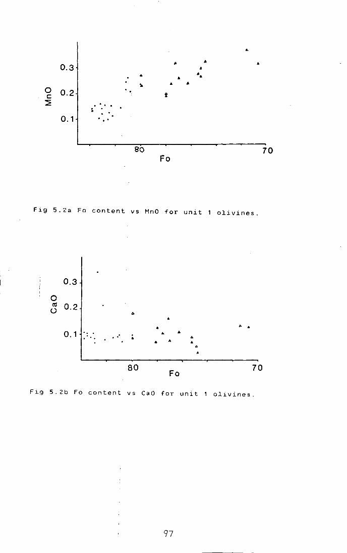
...
.. .. • 0.3 .II
... • ...
~ • • 0 0.2 t c: ~ . . . . . . . .
0.1 . . .
eo 70 Fo
Fig 5.2a Fo content vs MnO for unit 1 olivines.
0.3
0 ~ 0.2 ()
• .. A ..
0.1 .. . . • . . .. ... A
A .. .. • " ..
80 Fo
70
Fig 5.2b Fo content vs CaO for unit 1 olivines.
97

Di Hd r-~--------------------~ ,· ..
!:_~l. ...... . • ..
En Fs
Fig 5.3 Clinopyroxene compositions for LELS rocks. Heavy I
dashed field: all core compositions, solid line field: I
mean core compositions. Also marked: dashed I
line=Skaergaard trend, light dashed field: upper ELS and I
CS trend (Volker, 1983).
98

ex solved prior to
i I I I I i I ~he crystallisation of olivine,
although fractional ctystallisation of large amounts of I
olivine might be able to produce similiar effects. As I
the base of unit i~ not exposed, it is difficult to I
choose between these ~ypotheses.
I 5. A. 1 . c
I Ma,nganese contents
I
As with Ni!. I
only a few analyses from Unit 1
are available. They /show a fairly good linear decrease
in MnO with increas~ng Fa (Fig 5.2a). f b t 0 35% 1
rom a au . . I
MnO at Fo70
to about 10.15% at Fo84
. This trend is rather . . I
less r1ch 1n MnO and has a less steep slope than that I
found by McClurg (19B2) and Volker (1983) for upper ELS I
and CS olivines. I
I 5.A.1.d Calcium contents
I The unit 1/data is shown in Fig 5.2b. There is
little correlation ~ith Fa contents, and most olivines i
contain about 0.1% CaO similar to the values reported I •
by Simkin and Smith (1970) for basic plutonic rocks. I
although two analysef from sample U1P2 show anomalously
high CaO contents of ca. 0.3% CaO. This is similar to I values for quickly cpoled basic lavas (Simkin and Smith, I
1 9 7 0) . McClurg ( 1 9 8 2) I
and Volker (1983) report CaO
contents
and CS.
in the range 0.027. to 0.16% for the upper ELS I
I i I I I
5.A.2 CLINOPYROXENES
Plotted I ion I
the traditional pyroxene
quadrilateral, the /clinopyroxenes of the Lower E. L. S.
fall in a I .
bana~a-shaped f1eld around the I
Diopside-Salite-End~opside-Augite boundary (Fig 5.3). I
The mean core compositions for given rocks define a I
fairly good linear /trend parallel to, but rather more I
calcic and magnes~an than, the Skaergaard trend (Fig
5 . 3 ) I I i
Similiar relat~onships were noted by Volker(1983). I
althogh his clinop~roxenes (from the Upper E.L.S. ,c.s. I
and associated gabbros and dykes). while defining a I I
trend parallel to that of Skaergaard, are more calcic I I
I
99

! I
• I and magnes1an still (Fig 5.3).
. . . i It 1s 1nterest1ng to note that although there is
I some overlap betweer the Upper E.L.S./C.S. field and
that of the Lower E/.L.S., the Lower E.L.S. pyroxenes . i
be 1nterpreteo simply as the products of magmas I
cannot
produced by high l~vel fractionation of the more
ultrabasic magmas s~en elsewhere on Rhum, because of I
their lower Wo conten1t at a given Mg/Fe ratio. I
Also noteworthy /is the fact that the clinopyroxenes
from the 'Sheetrock~' fall on a continuous trend from I
the Lower E.L.S. peridotites, but are m~rkedly less I
calcic than those frdm the gabbros and dykes analysed by I
Volker; perhaps th~s supports the notion that the
sheetrocks I
are fractionated Lower E.L.S.cumulates, I
rather than gabbro~ like those seen elsewhere on the
island. I I I j
Pyroxene compositions seem to be independent I
of habit. In samples:with both cumulus and intercumulus
pyroxene, compositipns are almost constant. This has I
been reported by others (eg Dunham and Wadsworth, 1978). I
5.A.2.a AQ..uminium i
Aluminium ~anges from 0.17 atoms per 6 oxygens I
to 0.06 atoms per 6/ oxygens. (4.02- 1.85 wt "/. Al2
03
).
Al shows a slight +~e correlation with magnesium number I
(Mgn) of the clino~yroxenes (Fig 5.4a), although there
is much scatter. Th~ peridotites show slightly higher Al I
contents than I
the I allivalites, although the fields I
overlap. Pyroxenes lfrom the mixed layers tend to have
low Al contJnts for a given Mgn. Volker (1983) rather I
I reported Al 0 cont~nts in the range 4.7 to 3.0 wt "/. for
2 3 1 the CS, and 3.5 - 2!2 wt "/. for the upper ELS.
I
Al. caiculated as (2-Si) on the basis of 6
oxygens, is
activity of
crystallized
1V '
usually related inversely to the silica i
the ~elt from which the clinopyroxenes I I
(Le Bas, 1962). Al. shows a slight +ve j 1V
correlation with ~gn in the allivalites, but in the I
peridotites there ~s a suggestion of a -ve correlation I
.I ( F i g 5 . 4 b ) . A c cord 11n g
I I.
with fractionation ;1s i I I
to Le Bas ( 1 9 6 2) ' increasing Al. 1V
a feature of silica-undersaturated
\00

0.20
0. 15
0. 10
_.Jo. o5 <
0.00
0. 70
+
0. 75 MGN
0.80
+
0.85 0.90
Fig 5.4a Mg/M~+Fe (atomic)=MGN, vs Al per 6 oxygens for I
LELS clinopyroxenes. Crosses: allivalites, up-pointing
triangles:
peridotites.
0. 14
0. 12
0. 10
>0. 08 _.J <
0.06
0. 70
Fig 5. 4 b
I
m~xed I
layers, down-pointing triangles:
I A1 I I
+ +
v+ 6 ++ 9
i ~+~! + + 9
99 + + 1 9 9
+ + 9;t + 6~ ' 9 ~6 + 6 +V 9
++9 t +"\> 99 9 *14 '+%9 6 '\. + 9 +~ ~~~r-6 9 4- 9 +\'V
-tt <I>+ + + ++ + + +++ ;-:~:- ++* 9 9 ...... + + + +
+ ~~ .... +' + + + v 99 +...._. 6~
++ * ++* + * 9+ 9 ++ 9 6 l/i $
+ + 9 + 9 t-- 4 ++ + "'+ + ++ ''~-'- +
t -#'-++ + +++ _.. ++
+ ++ +il- +
'1t-
0. 75 MGN
* + + + +
+
* + + +. +++ 96+ + 9 + + 96 + 6 +9 + ~9 9
+ + 9 6 9
+9 9
0.80 0.85
+
0.90
in tetrahedral sites vs MGN for LELS
clinopyroxenes. Symbols as above. I I
101

0.06
0. 04
0.02
0.00
0. 70 0. 75 MGN
+
+
0.80 0.85 0.90
I I Fig 5.5 MGN ~s Ti per 6 oxygens for LELS clinopyroxenes. I
Crosses: al~ivalites. up-pointing triangles: mixed I
layers, dow~-pointing triangles: peridotites.
0·03
0·02.
ex u 0+01
0
0. 70
I I I I
I I
I I I I I I I I I I I
! I
+
0. 75 MGN
+
+ +
o. 80
Fig 5.6
Symbols
MGN vs Cr per 6 oxygens I I
aS above. I
\02
+
+
96 "i1 -f+
+
0.85 0.90
for LELS clinopyroxenes.

I I
magmas, while decreasing Al. is a feature of silica-' l.V I •
saturated magmas. ~hl.s suggests two trends in the LELS: !
an alkaline inte~stitial peridotite trend, and a I
tholeiitic alliva~ite trend. The considerable overlap
between these tre~ds can be explained by a certain I
amount of mobility bf the interstitial liquids. I
I I
5.A.2.b Titanium I
Titanium tontents are in the range 0.01 - 0.06 I I ions per 6 oxyge~s (0.26 - 2.06wt/. Ti0
2J, although
I values at the upper end of the scale are not common.
I Plotted against M~n. the peridotite pyroxenes are
clearly richer in ~i at a given Mgn than those of the I
allivalites (Fig ~.5). While the latter show little I
correlation with M~n. most of the peridotite pyroxenes
fall on a trend of i~creasing in Ti with fractionation. I
Clinopyroxene Ti cbntents are often related to the I
silica activity of\ the melt (Le Bas, 1962); thus the . I
enhanced Ti contents, of peridotite pyroxenes support the I
notion of an interstital alkaline trend. I I I I .
5.A.2.c Cmrom1.um I
Chromium c~ntents vary from 0.44 ions per 6 O~y~~,
to below detection ~imits (1 .53 - 0.0 wt 7. Cr2o
3J. Cr
shows a +ve correlat~on with Mgn (Fig 5.6), although the I
scatter is consider~ble, and the peridotite pyroxenes I
tend to have high~r Cr contents than those of I
allivalites. Volker r~ported Cr2
o3
contents in the range
1.69 - 0.54 for the ~s. and 1.32- 0.46 for the upper I
ELS. 1
I I I
5.A.2.d So~ium
Sodium cont~nts fall in the range 0.07 - 0.02 I
ions per 6 oxygens ( 1 \02 - 0. 3 wt 7. Na 2o). Precision for
Na using EDS analysi~ is rather poor however despite I I
this there is a tendency for the peridotite pyroxenes to I
have slightly highe~ Na contents a a given Mgn (Fig '
5.7). Volker (1983) r~ported pyroxene Na contents in the
range 0.6 to
pyroxenes to
I
0.2 w~ /., with a tendency for the CS ' '
have h~gher contents than those of the
103

0. 08
0.06
0. 04
<0. 02 z
0.00
0. 70 I
0.175 MGN1
I I
Fig 5.7 MGN vs Na p~r I
Crosses: allivalite~. I
layers, down-pointing I
85
80
z 75 t.:l I:
70
+
+
70 FO
I I
I
+
+
+
0.80 0.85 0.90
6 oxygens for LELS clinopyroxenes.
up-pointing triangles: mixed
triangles: peridotites.
+
+
++ +
+
* + +
75
+ + t
+* +
+ ... ++
80 85
Fig 5.8 Relationship ?etween olivine Fa content and Mgn
of Curve M~an values for each sample. I
clinopyroxenes.
shown is I
from Obata e~ al ( 1 9 7 4 ) indicating equilibrium I
at The LELS samples lie on the high temperature
side of this line.
I 04-

I I I
upper ELS. I I I
5.A.3 C~inopyroxene - olivine relationships
There isl a good correlation between Mgn of I
clinopyroxene and 1 Fo content of olivines in the same I
rock (Fig 5.8) It pas been recognised that slow cooling
of an olivine-clinbpyroxene pair will result in Fe-Mg I
exchange between the two phases (eg Speidel and Osborn, I
1967) the olivine1 becoming more Fe-rich, and the i . .
pyroxene more mag~es1an. Th1s has been used as a I
geothermometer (Obata et al 1974; Powell and Powell, I
1974). but poor constraints on the olivine-cpx system i
(Wood, 1978), and !interference by other Fe-Mg phases I
such as orthopyroxe~e and spinel, limit its usefulness.
Despite these limitaltions, it is likely that subsolidus I
Fe-Mg exchange has o~curred in the LELS rocks (Fig 5.8)
Another abproach is provided by the work of
Duke (1976). He defermined equations relating Fe/Mg
ratios of olivinesl and clinopyroxens to those of the I
liquids from which t~ey crystallised. Applying these to I
rocks from the LELS (Table 5.2). it can be seen that the !
clinopyroxenes in algiven rock have apparently cryst-1
allised from more m~gnesian liquids than the olivines. I
This is contrary t9 what would be expected from the
order of crystallisa~ion. Apart from demonstrating that i
the mineral compos~tions are not primary, this would I
also seem to rule ou~ equilibration of both phases with
interstitial liquids\ as being the final control on
mineral compositions. I I
It is like~y that elements other than Fe, Mg I
and perhaps Ca. ar~ less prone to post-cumulus I
!eequilibration due fo their high ionic charge, and/or
lack of suitable chemical gradients to induce diffusion. i
However there is no ~xperimental evidence on diffusion
rates in clinopyroxe~es, and this must be considered a
provisional conclusioi. There is some indirect evidence
that Cr has very slow diffusion rates, in that Duke I
(1978) found it impqssible to attain equilibrium Cr I
partitioning between blinopyroxene and basic melts.
I OS"

Sample number Fa Mgn LFo L Mgn U1A2 79.2 84.2 0.875 0.606
U2P1 84.5 86.6 0.613 0.472
U4A3 70.5 78.5 1 . 3 9 5 1 . 0 0 5
U4A15 70.0 7 6. 1 1 . 4 2 9 1 . 2 0 0
U5A1 76.2 8 2. 1 1 . 0 4 1 0.743
U5A17 76.6 80.2 1 . 0 1 7 0.872
Table S·l Liquid Fe/Mg ratios calculated from olivines
and clinopyroJenes in selected L.E.L.S. rocks, using the
equations of I Duke ( 1976). L =molar Fe/Mg ratio of Fa
liquid calcu~ated from olivine. LM =molar Fe/Mg ratio
· · d I 1 t d 1· gn of l~qu~ calcu a e from c ~nopyroxene.
10(:,

5.A.4 Plagioclase I
Plagio~lase has not been analysed extensively I
as preliminary :investigationshave revealed extensive I
within-sample v~riations. This has also been found by I
other workers i~ Rhum rocks legs Dunham and Wadsworth,
1978; Volker,198J Tait, 1985).
The tot~l range recorded (cores and rims) from I
LELS rocks is from An to An although this is 89.5 59.1'
unlikely to be the total range, as it is based on a I I
small
points
number of:samples only. The following general I
can perhaps be made: I I
(i) Th~re is little systematic difference I
between plagiocla\ses in allivalites and poikilitic I I
plagioclases in 'peridotites. The two groups are I
indistinguishable :on the basis of An content. The most I
calcic
part
grains
plagioclasks are cumulus grains from the lowest I
of Unit 1 a+livalite, while compostions down to I
have been fqund at the margins of both cumulus I
in Unit 3 ~llivalite, and in poikilitic grains I I
from Unit 3 perido~ite. I
Zon:ing. I
( ii) which may be normal, reverse
and/or oscillatory is widespread, and is not always
obvious optically.
(iii) The 'sheetrocks' from units 4 and 5 seem
to have relatively evolved plagioclases (usually less
than An70
cores). ~ut do not have rims more sadie than I
other LELS plagiocl~ses.
(iv) Plag~oclase An content is very sensitive I
• I • to small fluctuat1ors 1n water pressure,as well as to
I
melt Na/Ca ratios.\ Given the additional tendency for I
disequilibrium part~tioning of ions during crystal I I
growth (Smith and :Lofgren. 1983). the lack of I
correlation between\ plagioclase Na/Ca and the Fe/Mg
ratio of accompanyin~ phases is perhaps not surprising.
7 1 . In
5.A.5
\ I
I I Orth1opyroxene
I
Orthopyrox~nes show a range in Mgn from 86 to I
all rocks where it has been analysed,
orthopyroxene is slig~tly more magnesian than coexisting I
107
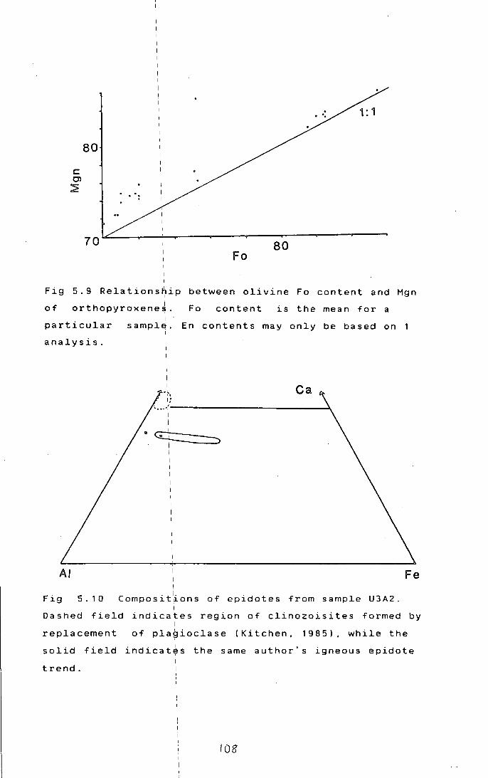
c: 0> ~
80
70 80 Fo
Fig 5.9 Relationship I
between olivine Fo content and Mgn I of orthopyroxene~.
I particular sample.
I
analysis.
I
Fo content is the mean for a
En contents may only be based on
Ca
0 G:C:::: ____ =:>__.
AI
Fig 5.10
I I
Composit~ons of epidotes from sample U3A2. I
Dashed field indicates region of clinozoisites formed I
Fe
by
replacement of plagioclase (Kitchen, 19 8 5) , while the I
solid field indicat~s the same author's igneous epidote
trend.
I 08'

I
I I I I i
olivine, but lefs magnesian than clin~pyroxene in the
same rock (fig: 5.9). It is likely that subsolidus
equilibration is a major factor in this, as has been I
found between ol~vine and clinopyroxene (Section 5.A.3).
specimens
I I
5.A.6 \Sulphides
Sulphides have I
from lunit I
1 :
been analysed in three
U1P2, U1P3, and U1A5. A.R.
Butcher and R.~.D. Pattrick kindly carried out these
analyses at Man~hester University.
There a\re few differences in chemistry between
individual phasesl in the peridotite and the allivalite, I
although copper bearing sulphides appear to be modally I
more abundant in ~he allivalite (section 3.C). However a
few sulphur-rich\ phases occur only in the allivalite,
suggesting
alivalite.
a l .
sl~ghtly h~gher sulphur activity in the I
Pyrit~ and. iron-rich violarite, the latter I
sometimes with aifew per cent Co, are the sulphur rich I
phases (Table 5.3\.
A . I. f str~~~ng feature o the assemblage as a
whole, is the rar~ty of chalcopyrite sensu stricto. Most I
of the grains an~lysed as chalcopyrite on the basis of I
optical propertie;s, are iron-rich, and oftefl metal-
deficient, fallinJ between cubanite and chalcopyrite in
· · o I · d 1 1 t th compos~t~on. ne 1
analys~s correspon s c ose y o e
mineral haycockit~ (Cu4
Fe5
s8
J, but others do not
correspond to any clearly defined, described phases. I
They do, fall within the intermediate solid however I, I
(iss) fi~ld of the system Cu-Fe-S (Craig and solution I
Scott, 1982). Within this broad group, two types can be I
distinguished in the Unit I
samples: ( i) metal deficient
(or sulphur enric~ed - this is not distinguishable on I
the evidence of probe analysis alone) Cu,Fe,S phases
with I Cu:Fe 2:1 to 11:1, and (ii), stochiometric Cu,Fe,S
phases with I Cu:Fe from 1:1.1 to 1.5:1. The iss field I
includes the phasss cubanite, mooihoekite, talnakhite, I
haycockite and cha~copyrite, among others, and these are
normally the
compositions.
I
' ph a s:e s I
Howe:ver '
formed on cooling iss bulk
parts of the iss are regarded as
being capable of f~rming metastable superstructures on I I I
I I 109 I I
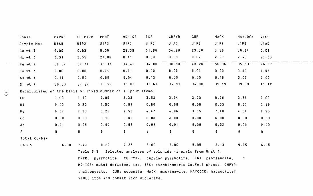
0
Phase:
Sample No:
Cu wt 7.
Ni wt 7.
Fe wt 7.
Co wt 7.
As wt 7.
S wt 7.
PYRRH
U1A5
0.00
0. 31
59.87
0.00
0 . 11
39.83
CU-PYRR
U1P2
0.93
2.55
59.74
0.00
0.50
37.27
PENT
U1P3
0.00
27.06
38.37
0. 74
0.00
33.59
MD-ISS
U1P2
29.39
0 . 11 --
34.45
0.01
0.54
35.05
ISS
U1P3
31 . 68
0.00
34.80
0.00
0. 13
35.60
CHPYR
U1A5
34.68
0.00
30.98
0.00
0.05
34.91
CUB
U1P3
23.50
MACK
U1P2
3.38
0.07 2.69
40.20
0.00
0.00
34.90
56.96
0.00
0. 19
3 5. 19
Recalculated on the basis of fixed number of sulphur atoms:
Cu 0.00 0.10 0.00 3.33 3.53 3.94
0.00
4.06
0.00
0. 01
8
2.00
0.00
3.95
0.00
0.00
6
0.38
0.33
7.40
0.00
0.02
8
Ni
Fe
Co
As
s Total Cu+Ni+
Fe+Co
0.03
6.87
0.00
0. 0 1
8
6.90
0.30
7.33
0.00
0.05
8
7.73
3.50
5.22
0. 1 0
0.00
8
8.82
0.02
4. 50
0.00
0.06
8
7.85
0.00
4.47
0.00
0.02
8
8.00 8.00 5.95 8. 13
Table 5.3 Selected analyses of sulphide minerals from Unit 1.
PYRR: pyrrhotite, CU-PYRR: cuprian pyrrhotite, PfNT: pentlandite,
MD-ISS: metal deficient iss, ISS: stochiometric Cu,Fe,S phases, CHPYR:
chalcopyrite, CUB: cubanite, MACK: mackinawite, HAYCOCK: haycockite?,
VIOL: iron and cobalt rich violarite.
HAYCOCK
U1P3
30.84
VIOL
U1A5
0. 01
2.46 23.59
35.03 26.67
0.00
0.00
39.39
3.78
0.33
4.94
0.00
0.00
8
9.05
7. 56
0.00
4 1 . 1 2
0.00
2.49
2.96
0.80
0.00
8
6.25

cooling
the case
analysis
I
I (Craig and Scott, 1982), and this appears to be
in uniJ 1. I
Phasesl identified on the basis of microprobe I
are a1s follows: pentlandite (25 analyses), I
pyrrhotite (24 analyses), metal deficient Cu,Fe,S phases
( 2 5 1 ) I . . ana yses , : stoch1ometr1c Cu,Fe,S phases (20
1 . I ana yses; 1ncl~des chalcopyrite and cubanite).
I mackinawite (5 i analyses), pyrite and haycockite (1
I analysis each). 1
and violarite group minerals (2
analyses) Sele~ted analyses of these phases are given
in Table 5.3. I
The a4semblage recorded is fairly typical of
magmatic sulphid~s associated with basic and ultrabasic
rocks. Certain p1
hases, eg mackinawite, appear only to
form with conti~ued equilibration to low temperatures,
while others, p~incipally the poorly defined iss
compositions, ar~ thought to be associated with rapid
quenching. Given ~he size of the Rhum intrusion, and the
evidence for subkolidus exchange between sulphides and I
olivines ( sectioh 5. A. 1. b). rapid cooling seems !
untenable. Interpretation of this assemblage in terms of I
published phase ~iagrams (eg Craig and Killerud, 1969) I
is thus very difficult; however as Craig and Scott I
(1982) have said of experimental sulphide phase I
relations: " .. reJ.lationships remain enigmatic. obscured I
by extensive sdlid solutions, unquenchable phases and I
metastability.". iThere is no reason to expect natural I
assemblages to be !any better behaved.
! I
5.A.7 Kaersutites I
Two kaersutite analyses from sample U2P8 are I . . . . .
given in Table 5.4~ These are s1m1lar 1n compos1t1on to
intercumulus kaersLtite analyses given by Volker (1983) I
and Kitchen (1985). The Cr contents are notably high-
Cr contents were: not given in earlier analyses. I
Available data (~enderson, 1984), suggests that
amphibole would ha~e about the same, or smaller affinity '
for Cr than clinopyroxene. Cr contents of the latter I I
phase in U2P8 are :o. 5Z - 0. Bl. This may imply that the I I
late-formed kaers~tite grew from a Cr-rich liquid, and
I\\

Phase:
Si02
Al203
FeO*
MgO
CaO
Na20
K20
Ti02
Cr203
Total
Table
Kaer:
core,
4 3 .14 5
1 o .. a 5 I
6.87 I
1 6. 1
1 a
1 2 . r 2
2.96 '
nd I
4 . 9 1 I
1 . 3 0 I
9 a. 1 4
Ph log
3a.04
1 3 • 6 1
9.32
1 7. 53
0. 1 5
0.74
9.52
7.37
nd
96.2a
Hbl(c) Hbl(r) Epi
4a.57 43.26 39.20
a.31 11.72 29.17
a.72 15.30 5.60
15.49 10.9a 0.3a
12.6a 12.46 24.a6
1.20 2.a5 0.29
0. 1 3 0. 0 6 nd
o.a5 0.21 0.00
nd nd nd
95.95 96.a4 99.50
Unk
42.34
22.5a
0.09
0.02
25.79
0.25
0. 1 6
0.06
nd
91 . 2 9
5.4 Selected analyses of minor phases from the LELS. I
kaers~tite, Phlog: phlogopite, Hbl(c): green amphibole
( I) . . E . . . Hbl ~ : green amph~bole r~m. p~: ~ron-r~ch I
clinozoisit~. I
Unk: unidentified mineral (see also text).
FeO*= iron expressed as FeO. nd: not determined.
t I '2.

not a liquid depleted in Cr by extensive crystallisation
of chromite and/br clinopyroxene. This thus supports the
idea (Section 51.A.2) that peridotites were permeable,
and the interstitial liquids were capable of movement . I
and replen1shment.
sample
at the
5.A.8 Hydrous minerals in allivalites
Two eridotes from the hydrous assemblage in
U3A2 have been analysed (Table 5.4). These plot
Fe-poor end of Kitchen's (1985) igneous trend
(Fig 5 . 1 0) and away from the field of clinozoisites
formed by replacement of plagioclase, supporting a . J .
late-magmat1c or1g1n for the mineral (Section 3.C.3.b). I
Analyses of cores and rims of green euhedral I
hornblendes fr~1 the same assemblage indicates
pronounced zon1ng, the cores being magnesia-hornblende
and the rims bei~g edenitic hornblende (nomenclature of
Leake, 1978). I Phlogo1=1ite from the same sample is highly
titanian (Table 5.4).
The unidentified brown mineral (section
3. c. 3. b) is a calcium aluminium silicate, presumably
with much water, as all analysed grains gave totals
around 90-917. (Table 5.4).
5.8 SOME ASPECTS I' XENOLITH MINERAL CHEMISTRY
5.8.1 Pigeonite
Inverte~ pigeonite grains from sample 194c I
(see section 3.f.3.d) have been analysed. The
host-lamellae re~ationship (Fig 5.11) indicates that
these were a~ thel Mg-rich end of the pigeonite stability
range in bas1c rocks. The presence of hypersthene in an
adjacent layer in I the same rock indicates that this rock
was formed at t~e hypersthene- pigeonite transition,
which is commonly at an Mg/Fe ratio of about 70:30 I
(Brown, 1972). ~oexisting plagioclase is An 74 . Less I
calcic plagioclases occur in the LELS units, but no such I I
evolved pyroxenesJare seen. As plagioclase An content is
very dependent on p ; this may imply that more evolved H20
113

En
Fig 5.11
Di Hd ·,-~----------------------~
I
I I I
' 6
0
'
Host~tame11ae relationship in inverted
Fs
I pigeonite from sample 194C. Solid field is range of LELS
I orthopyroxenes.
114
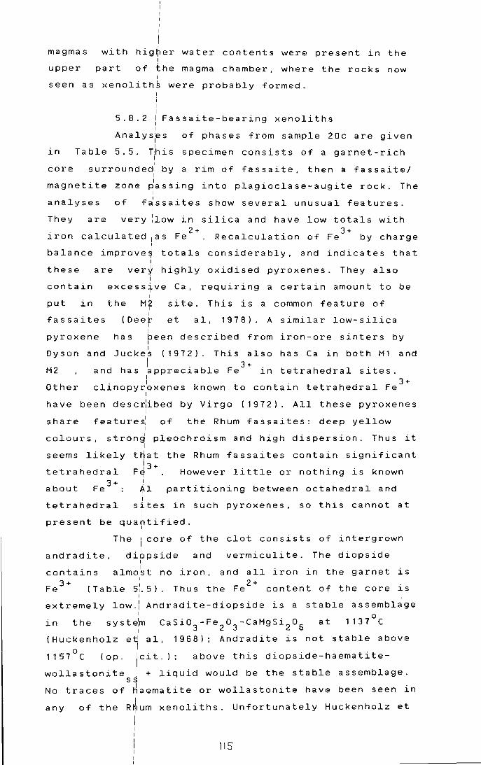
I I
I magmas with hig~er water contents were present in the
I
upper part of the magma chamber, where the rocks now I
seen as xenoliths were probably formed. I
in Table
! I
I
5.8.2 I Fassaite-bearing xenoliths I I
Analys~s of phases from sample 20c are given I .
5.5. Tr1s specimen consists of a garnet-rich I
core surrounded by a rim of fassaite, then a fassaite/ I
magnetite zone Jassing into plagioclase-augite rock. The I
analyses of f~ssaites show several unusual features. I
They are very :low in silica and have low totals with I 2 + 3 +
iron calculated 1as Fe Recalculation of Fe by charge
I balance improve~ totals considerably, and indicates that
I
these are very highly oxidised pyroxenes. They also i
contain excessive Ca. requiring a certain amount to be I I
put in the M2 site. This is a common feature of I
fassaites (Deer et al, 1978). A similar low-silica I I
pyroxene has been described from iron-ore sinters by I
Dyson and Juckek (1972). This also has Cain both M1 and
2 h I . F 3+ . . M and as apprec1able e 1n tetrahedral s1tes.
. I . 3+ Other cl1nopyroxenes known to conta1n tetrahedral Fe
I
have been desc~ibed by Virgo (1972). All these pyroxenes I
share feature~ of the Rhum fassaites: deep yellow I
colours, stron~ pleochroism and high I
seems likely that the Rhum fassaites
dispersion. Thus it
contain significant
tetrahedral 13 +
F~ However little or nothing is known
about 3+
Fe : I
-4-l partitioning between octahedral and I
tetrahedral sites in such pyroxenes, so this cannot at I !
present be quantified. I I
The i core of the clot consists of intergrown
andradite, dibpside and vermiculite. The diopside I
contains almo~t no iron, and all iron in the garnet is 3 + I 2 +
Fe (Table 5:.5). Thus the Fe content of the core is I .
extremely low./ Andradite-diopside is a stable assemblage I 0
in the syst~m CaSi03
-Fe2o
3-CaMgSi 2 o6 at 1137 C
I
(Huckenholz e1 al, 1968); Andradite is not stable above
1157°C (op. /cit.); above this diopside-haematite
wollastonite I + liquid would be the stable assemblage. ss
No traces of Maematite or wollastonite have been seen in I
any of the R~um xenoliths. Unfortunately Huckenholz et
I
\IS
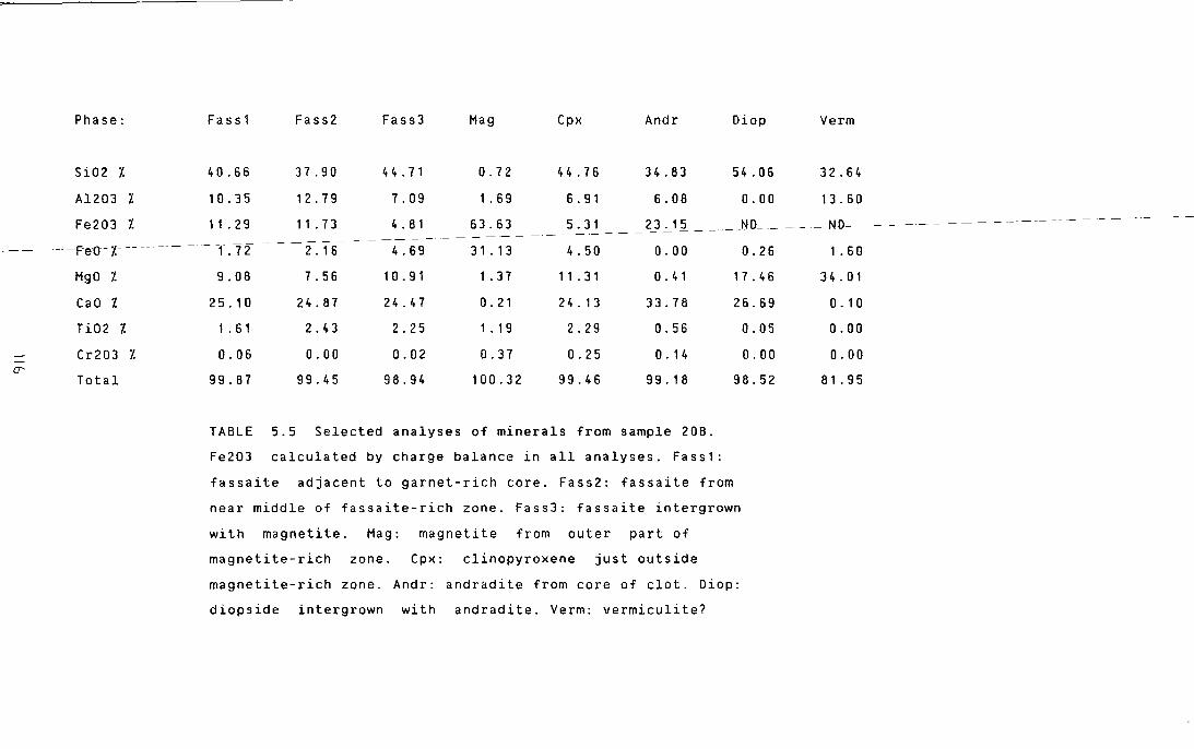
Phase: Fass1 Fass2 Fass3 Hag Cpx Andr Diop Verm
Si02 7. 40.66 37.90 4 4 . 71 0.72 4 4 . 7 6 34.83 54.06 32.64
Al203 l 10.35 12.79 7.09 1 . 6 9 6. 91 6.08 0.00 13.60
Fe203 l 11 . 2 9 11 . 7 3 4. 81 63.63 5. 3 1 __ 2_3 . 12 _ _ _ JW_ _ - - - N D- - - ----------------------------- -F-eo-z--- ------- - T .72 2. 1 6 4.69 31 . 13 4.50 0.00 0.26 1 . 6 0
HgO l
CaO l
Ti02 7.
Cr203 l -(]'
Total
9.08 7. 56 1 0. 91 1 . 3 7 11 . 3 1 0. 41 1 7. 4 6
25. 1 0 24.87 24.47 0. 21 2 4. 13 33.78 26.69
1 . 6 1 2.43 2.25 1 . 19 2.29 0.56 0.05
0.06 0.00 0.02 0.37 0.25 0. 14 0.00
99.87 99.45 98.94 100.32 99.46 99. 18 98.52
TABLE 5.5 Selected analyses of minerals from sample 208.
Fe203 calculated by charge balance in all analyses. Fa s s 1 :
fassaite adjacent to garnet-rich core. Fass2: fassaite from
near middle of fassaite-rich zone. Fass3: fassaite intergrown
with magnetite. Hag: magnetite from outer part of
magnetite-rich zone. Cpx: clinopyroxene just outside
magnetite-rich zone. Andr: andradite from core of clot. Diop:
diopside intergrown with andradite. Verm: vermiculite?
3 4 . 0 1
0. 1 0
0.00
0.00
81.95
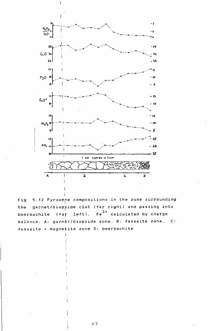
Fig
the
1 ··..,..---"' ..., __
2.5r_- __ .J __ -. ..,___ _ ___ .o. ........... ---""----
ro .~· ': ···o- •... ,. .. -· ..... ...... ..;>.. ""··- .. ; 14
11} 1 .. -11 11 Fl.!lO 10 __ .o-.1__ -<> _ •• .o----~----o--··a·· • IO
... ''0- ___ ',' ... o---~-o... p-----o-"'
11 I ·-. .-- • o ·v
I
llt•···C>-t••-o. .... .,..••""""•"""~--· •"'-•••-q_"o0
D 11 I '·a..
16 ' - • ..,_ - 10
I •• - -o.. •• _..,..-.-a._·-.
I . •
Al 0 ::r-----~------<>-· -o ........ ----A·--.-o--··"""--- ~ ·,: ,. "l . ..,__ I -.... -- -<>·-- ·O
5 ' ·-.,o S
.o
4~t ---· o-···<)··· • 4S I ,.,...--o .SiOA t:J----<>· ~--o- •• ·o- •• -o-···"'·,., ... .o- ... o-··· • 4.0
- I '"IY'
u I ~ I ""' OPf"'Oil a I"'"'
A
5.12 Pyroxe~e compositions I
garnet/diopride clot
in
c.
the zone surrounding
beerbachite (far left l.
(far right) and passing into 3+
Fe calculated by charge
balance. A: garnet/diopside zone, B: fassaite zone, C: I
fassaite + magnetite zone 0: beerbachite
117

al ( 1 9 6 8) not give f(02
l conditions for their
experimental wprk, and the dependance of phase relations
in this system! on f02
are unknown. The fine intergrowth
of andradite ahd diopside in the Rhum xenoliths suggests I
inversion fromla homogeneous higher temperature phase.
Ther~ is a gradation in optical properties of
the pyroxene !from the core to the margin of the clot
(Section 3.C.3Jd). The variation in pyroxene composition
across this zo1e is shown in Fig 5.12. Al2o
3, Fe 3 +/Fe 2 +
total Fe and Ca all tend to decrease from the clot to I
the enclosing !beerbachite, while Si02
and MgO show the
opposite trend.l . I 3 + 2 +
The IFe /Fe ratio indicates a progressive
decrease in fl 02 from the core of the clot to the
beerbachite (Fi~ 5. 12). In the latter the pyroxenes have 3 + 2 + I
Fe /Fe abou~ 0.5 or less, while in the former all
iron is Fe3
,I held in andradite. The fassaites have
intermediate +okidation values. At clinopyroxene 3 + 2 + . I
Fe /Fe rat1os of 4-0.6, magnetite is intergrown with ! the fassaite. 13+
clot,
Fe must have I
this sug9ests that at high Fe and f02
.
As been diffusing out of the
Fe 3 + goes
into fassaite. tt lower Fe levels, and with appreciable 2+
Fe ' 3 +
present, magnetite is the main sink for Fe and
at still lower fie levels and lower f 02
, ·normal' augitic
pyroxene can take up the Fe 3 + The coexisting gradient in I
aluminium concerltration will also play an important role I •
in stabilising ~assa1te.
5 . C C 0 N C L U S I 0 N s!1 (i) The olivines and clinopyroxenes of the
LELS show a wi~er range in composition and are less
magnesian than i those from other parts of the Rhum
ultrabasic complrx.
(ii) S~bsolidus equilibration has modified the I
chemistry of thei cumulates, particularly with regard to
Mg/Fe ratios of Werromagnesian silicates. I
(iii) :The interstitial clinopyroxenes in
peridotites I
evo-1-ve along a different trend to the
clinopyroxenes bf allivalites. The peridotite trend is I
! 118 I

marked by highbr Al. Ti. Na and Cr. . I l. v
( l.V) I. Early formed orthopyroxene oikocrysts in
allivalites are often replaced by alkaline amphibole!
rich assembla~es. This suggests that the interstitial I
liquids in L~LS peridotites may have originally been . . I . .
Sl.ll.ca-saturated, but were at least part1.ally, dl.splaced I
by later undersaturated liquids. A possible mechanism I
for this is di~cussed in Chapter 7.
(v) !sulphide
exsolved frorr\ the
blebs in Unit
magma prior to
may have been
olivine . . I
crystall1.sat1.on, I,
as
chemistry of 1most
olivine Ni contents are low. The
sulphide minerals seems to be • I l.ndependent o~ whether they occur in the peridotite or
the allivalitJ, although pyrite and violarite are
restricted to t~e latter, suggesting higher f(S2
l in the
allivalite. The'l genesis of the sulphides will be further
considered in chapter 7.
(vi) I Basaltic xenoliths are associated with
very highly oxibised calcium-, aluminium-. and iron-rich I 3+
amygdale assemblages. Significant diffusion of Fe and 3 + 1.
Al outward fr9m these asemblages occurs over distances
of 1-2cm.
I 19

6.A. General
In order
CHAPTER SIX
CRYPTIC VARIATION
to examine the extent of cryptic
variation in the L.E.L.S. 90 samples were~collected over
a 250m vertical section near the Allt nam Ba.
I Clinopyroxene and olivine were analysed in all
samples ~here both were present. A few samples lacked
one or other phase. Plagioclase was not extensively
analysed las preliminary studies indicated that
within-sample variation was as great as or greater than I that between samples. This has also been found by other I workers on Rhum ( Dunham and Wadsworth, 1978; Volker, I
1983). At least 5 analyses per section were made of
clinopyrofene and between 3 and 8 of olivine. In most
cases o was less than 0.31. Fo, or MgX100/(Mg+Fe). In the I
case of clinopyroxene only core compositions were used,
as. ~a~g~fal ~oning both of cumulus crystals and
po~k~l~t~e gra~ns was frequently pronounced.
lEven where considerable changes in texture or
modal composition are present over the area of a given
polished lthin sectio~. variations in mineral Mg/Fe
ratios aFe not seen. Thus cryptic variation is not
detectablJ on a small scale in the L.E.L.S. rocks; it I seems to be on a larger scale than, and superimposed on
. I . the f~ne scale layer1ng.
!variations in Fo content of olivine and in Mgn
clinopyroxene (Mgn.=MgX100/(Mg+Fe)) with height are of I
shown in ~ig. 6.1: together with stratigraphic data from
the measuFed sect~on. The range in olivine compositions
is from IFo 85 _6 to Fo 70 ; thus olivine compositions
significantly more iron rich than any previously I
recorded from Rhum - Fo 74 L.E.L.S.
variation
The most
profile
obvious
are the
Palacz, 19 84) - occur in
features of the cryptic
"peaks" of Fo content
the
associated I
with peridotites. Nearly every peridotite,
even those <20cm
horizons lwithin
thick or present as discontinuous slump
allivalite show this enrichment in Fo
120

l.f1 (X)
0 CD
l.f1 r--
0 r--
-Height (mf ··
...... ·· .. ·· 250 . .. . . . . . .
·----- c ............... " . . . . . . . . .
w :·-::--::--::--:: 7 .·· .. ·· . .-· .. ·· ..
;;.::::::::::::::::: f- -::--::--::·-::-· - ....... . "Z ••••••• c
+--~.r200
c --·--·-
·>:~:::0-:-: ~50
~ }}:::::::. t _·_s)c_}·
--- ~-~· ·:~::...-- ---115 1-
" )
0
3 f-
·---··
r:-:-:-:-::-:: ~?'-
- - - - - - - - - - - - - 100 f-
'z l==n::::n:::i J
·~ s-s -+----+50
w --::--::--::--. z ...... .. 0 ··::--::--::--::
f.::--::--::--:.-· c ; f-:~:· ...... ·:
Mgn
Fig 6.1. Var.i!,ation of olivine Fo content (left), I
and clinopyr~xene Mgn (right) with height above I
base of the L!ELS. C -lowest appearance of cumulus I
c li nopy roxene lin each unit. Note expanded vert i ca 1 I
scale between 1100 and 125 m. Allivalite stippled. i I I 12!
I I I I I
compared wit~ the surrounding feldspar cumulates.
Conversely I
allivalite layers, I
even where thin or
disturbed, ar• marked by "troughs" of lower Fo content.
Progressive dJpletion of olivine Fo content with height I
in a unit is not usually seen, although there is a I
suggestion o~ general Fo depletion with height
particularly fn the allivalites of Units 3, 4 and 5. The I
other obviou~ feature of the cryptic variation profile I
is the pres~nce of "reversals" towards the top of
allivalite la~ers - i.e. the most evolved olivines are
seen some way ~elow the top of the layer. Conversely the
most magnesian\ olivines in peridotites are seen some way
above the basel I .
The ~rof2le shown by the Mgn of clinopyroxene i
follows that shown by olivine very closely, except in I
the peridotitelof Unit 4 and the central portion of Unit
allivalite.\ The former layer shows a much lower Fo
content than lather peridotite layers, and indeed the
olivines of t~e overlying allivalite are richer in Fo
than the perid9tite itself. This may be explained by the
presence of g~bbroic veins in this area ( see section
2c) perhaps .I . . ~nd2cat2ng that a subsurface gabbro
mbdified the chemistry of the cumulates at I
intrusion has
this level. Th~ situation in Unit 1 is problematic and
is discussed I
larer.
I
6.B . . I
02SCUSS20n~ I
There\is compelling evidence that the mineral
compositions of the L.E.L.S. have been modified by I
various post-cumulus processes. Work by Henderson and I
Suddaby (1971)J Henderson (1975) and Bevan (1982) has I . . . l shown, in Rhum ~nd other 2ntrus2ons that chrome sp2ne s
generally show dompositions which have been extensively I
altered by reaqtion with interstitial liquid and other I phases present.1
If such a process operates in chrome
spinel, it se~ms likely to operate in other phases. I
Butcher (1985) 1 has shown that late stage veins, I
representing ev~lved liquids I
in the cumulate pile '
emplaced along f~actures, have modified the chemistry of I
minerals, partic~larly olivine and chrome spinel in the I
I I

. I surround1ng cumulates over distances of 1-2 em. If
I
re-equilibrat~on can occur over such distances when the I
rocks are r~latively cool and brittle, then with hot
interstitial ~iquids in porous piles the process should
also be effellctive. This may explain the remarkable I
constancy of o~ivine compositions in individual samples. I
Further support for this comes from the fact that
olivines are hever zoned with respect to Fo, even when
co-existing ph~ses show extensive zoning, implying that I
any zoning h~s been eradicated by reequilibration. • . I •
D1ffus1on prof1les around calc-silicate clots in
beerbachites ffom unit 5, also indicate migration of Al I
and Fe over 1 distances of 1-2cm (chapter 5). It has
already been s~own (section 5.A.3) that the Fe/Mg ratios
of coexisting I olivines and clinopyroxenes indicate . I
subsol1dus exchange between the two phases, and probably I
involving the ~xide phases and orthopyroxene as well.
The lmost magnesian clinopyroxene should be
learliest formed cumulus crystals in seen as the I
allivalites, asl these represent the first appearance of
clinopyroxene o~ the liquidus. This is not the case. The
most magnesian! compositions are seen in the poikilitic I
pyroxene withih the Unit 2 peridotite, associated with I
the most for~teritic olivines. Generally the
clinopyroxenes I in peridotites are more magnesian than i
any in the overlying allivalite, and within allivalites I
intercumulus clinopyroxene low down is more magnesian I
than the first ~umulus grains higher up.
The !sympathetic relationship between Mgn of
clinopyroxene Jnd Fo content of olivine may provide a I
clue to this. There is no reason, assuming that mineral I
compositions are primary, why interstitial i.e. late I
formed clinopyioxene in a· peridotite should mirror the I
variation in ~o content of the cumulus olivines. The I
clinopyroxenes !crystallized from trapped liquid and
would be expect~d to show no variation, or a random one.
with height. The !sympathetic variation observed suggests I I
that olivine a~d clinopyroxene exercise a control on I I
each other's chemistry either by equilibration with late I I
stage migrating! liquids in the crystal pile, or by i I
I
-1 I I
12~

aJ
0
ILFo- LMgn
'() I
c.i I ' I
N 0
c.i .
0
Height (m)
:- ::--::··::--:: 250 ~::: .. ::..:: .. :: c .. - .... --.~-·· ,....
lu ::<::<::::::::: > : .. :: .. ::..:: .. :: v:: :::::::::::::::::
2 ·-::-.:: .. ::..:: c J F-'-'-~~
.-. .~. .~. .--.r. 200
Q' :::>:::::::::: J .......
~ >~>::::::: ':::><:::>:: 2 ·.:..:: .. ::..::-
:> ::::::;~:>:: c
0
3 1-
2
J
. ISO c
-----100
Fig 6.2 Var~ation in LFo-LMgn with height above I
base of the: LELS. Lfo= molar liquid Fe/Hg ratio I I
calculated from olivine, LMgn= molar liquid Fe/Mg I
ratio calculated from clinopyroxenes, using I
equations of Duke (1976). I
114-

I I I I I I
subsolidus Fe1Mg exchange.
The/ Fe/Mg ratios
with th 1.1 e c ~nopyroxenes and
of liquids in equilibrium
olivines of the LELS have
been I
calcula1ted using the equations of Duke (1976). I
Earlier thes~ were used to argue that subsolidus
equilibration/ had indeed occurred. The larger the i p o s it i v e v a 11u e of L
1-L , where L = liquid Fe/Mg
o cpx cpx ratio
Fe/Mg
I calcul!ated
I from clinopyroxene, and L
01= liquid
ratio 1 calculated from olivine, the greater the I
degree of ~quilibration. This parameter will thus be
related,
rocks
am~ng other things, to the rate at which the I
reach the blocking temperature for I
olivine-clinopyroxene I
Fe-Mg exchange. The variation of
this parameter with height is shown in Fig 6.2. Values I
are in the: range 0.0 to 0.3, apart from Unit 1
allivalite, /and the unit 3/4 contact. At the latter
level, I
there I
by I
for'
cumulates
account I
is evidence for late heating of the
gabbroic vein (section 3.B.4). This may
the greater degree of equilibration. The
situation i~ unit 1 allivalite is problematical and is
discussed l1ter. The allivalites of units 4 and 5 have
generally loL values similar to, or slightly lower than I
the other LELS rocks.
groups:
phases,
former
I
Thb above effects can be divided into two I
tho~e based on equilibration between solid
and1 those based on liquid/solid reactions. The I
see~ to have been the final control on mineral I
compositions;. explaining the parallel variation of
olivine an~ clinopyroxene; however it is likely that
subsolidus ~~ffects are only significant over small I .
distances (Ia few cent~metres at most l. To explain the
large scale cryptic variation it is necessary to I
consider th~ movement of interstitial liquids. I
I~ is clear that the pattern of cryptic I variation supports the idea of repeated replenishment of I
the Rhum magma chamber (Brown, 1956). There are two main I
models by :which the observed peridotite/allivalite
layering ca~ be produced in a replenished magma chamber. • I
In the f~rst type, of which the model of Brown (1956), I
is an example, each new batch of magma crystallises I I I I I 12S I

first l. . I
o ~v~n~. and then olivine + plagioclase as it
cools. Brown !envisaged a basaltic parent, but this is
not essentia~ to the model. In the second type, which I
was originall~ proposed by Huppert and Sparks (1980), a
dense, high-Mg basalt or picrite is the replenishing I
magma. This hot, dense liquid ponds at the base of the I
magma chambe~, under the lighter, cooler more evolved
liquids which (ave resulted from the crystallisation of
earlier cumulates. As the picritic layer cools, it
convects vigdrously and crystallises olivine, which
decreases thJ density of the new magma. Eventually the
density of thJ new magma will equal that of the old, and
as the temp~ratures of the layers approach equality,
convection sJJows down, and the interface between the I
layers breaks down. The allivalites crystallise from
"hybrid" magmJ produced by the mixing of the two layers. I
These two models will produce significantly
different cryJtic variation patterns. In the first case, I
the onset of olivine + plagioclase (ie allivalite)
crystallisatidn should occur at a constant compositional
point in each lunit. With the second model this need not '
be the case, ~s the onset of crystallisation of olivine
+ . l I plag~oc as~
relationships
is not controlled by the liquidus
of the magma, but by the composition of
the "hybrid" jliquid formed after the breakdown of the
picrite layel. If picrite influxes are small, then the
composition .If this hybrid magma will be dominated by
the old res~dual magma. This could lead to allivalites
· · I · t h · 1 t · ~n success~ve un~ s s ow~ng a more or ess con ~nuous
evolutionary I trend, punctuated by the intervening
peridotites. I
It is clear from Fig 6.1 that the change from
cumulus olivirle to cumulus plagioclase + olivine occurs I
at different I compositions in the LELS units. In
addition, palfticularly in units 3, 4 and 5, there is I
suggestion of !continuous iron enrichment with height in
the allivalites. This supports the model of Huppert and I
Sparks (1980);
peridotite
I I
The :pattern of cryptic variation suggests that I layers, with roughly constant Fa contents, at i I
12f.
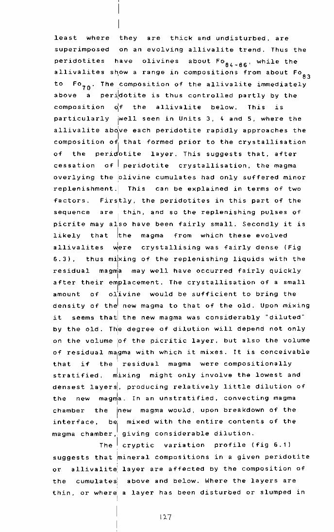
least where jthey are thick and undisturbed, are
superimposed lon an evolving allivalite trend. Thus the
peridotites have olivines about Fo84
_86
, while the
allivalites s~ow a range in compositions from about Fa I 83
Fo7 0
. The lcompos i tion of the allivalite immediately
per~dotite is thus controlled partly by the
to
above a
composition the allivalite below. This is
particularly 1
well seen in Units 3, 4 and 5, where the
allivalite ab~ve each peridotite rapidly approaches the
composition o, that formed prior to the crystallisation
of the peridotite layer. This suggests that, after
cessation of i peridotite crystallisation, the magma
overlying the ~livine cumulates had only suffered minor
replenishment ·I This can be explained in terms of two
Firsjtly, the peridotites in this part of the
sequence are thin, and so the replenishing pulses of
picrite may aJso have been fairly small. Secondly it is
that !the magma
factors.
likely from which these evolved I allivalites ~ere crystallising was fairly dense (Fig
6. 3) , thus milx ing of the replenishing liquids with the
residual mag~a may well have occurred fairly quickly I
after their emplacement. I
The crystallisation of a small
amount of oiivine would be sufficient to bring the
density of thJ new magma to that of the old. Upon mixing
it seems thatl the new magma was considerably "'diluted"'
by the old. T~e degree of dilution will depend not only
on the volume iof the picri tic layer, but also the volume
of residual ma1
gma with which it mixes. It is conceivable
that if the 1 residual magma were compositionally
stratified, Jixing might only involve the lowest and
densest layers!. producing relatively little dilution of
the new mag~a. In an unstratified, convecting magma I
chamber the lnew magma would, upon breakdown of the
interface, b, mixed with the entire contents of the
magma chamber,, giving considerable dilution.
The I cryptic variation profile (fig 6. 1)
suggests that ~ineral compositions in a given peridotite '
or allivalit~ layer are affected by the composition of
the
thin,
cumulates! I I
or where: I I
I
I
above and below. Where the layers are
a layer has been disturbed or slumped in
117
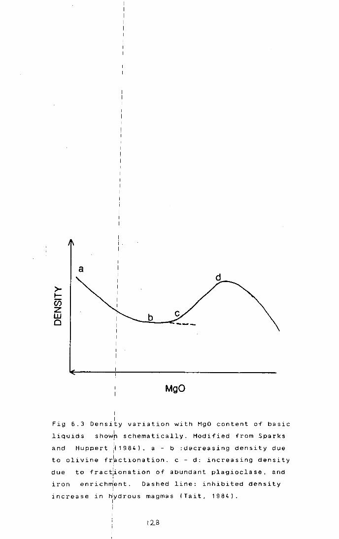
>.__ Ci5 z w 0
I I I
MgO
Fig 6.3 Densi~y variation with MgO content of basic
liquids showh schematically. Modified from Sparks I
and Huppert /( 1984). a - b :decreasing density due
to olivine fr~ctionation. c - d: increasing density '
due to fract~onation of abundant plagioclase, and
iron enrichm1ent. I
Dashed line: inhibited density '
increase in hlydrous magmas (Tait, 1984). I
1213

i I I I i
with the enclo~ing cumulates, the compositional contrast
is lower than/with thick and continuous layers. As the I
cumulates must have contained appreciable · nmounts of
intercumulus llquid for mixing to occur, it is tempting I
to view the lpwering of the compositional contrast as I
being due to e~uilibration with mobile pore liquids. The
intercumulus l~quid in a peridotite may be considerably I
• I more magnes1ar than that in an allivalite according to
the model of/ Huppert and Sparks (1980). Thus
mobilization ~f pore liquid from a peridotite into an I
allivalite wauld I
cause the allivalite olivines to
reequilibrate / to more magnesian compositions.
Conversely, ~ thin peridotite mixed with intercumulus
liquid from /an allivalite would be made over to more
iron-rich co~positions. The net effect of this process
will be t I • .
o ~ower the compos1t1onal contrast between
allivalites I
and I
peridotites where pore liquids are
mobilized between layers. I
Whiie I
shock-induced mixing can produce these
compositional/ effects in deformed layers, another • I • mechanism 1s
1requ1red to explain the reversals in the
I • • parts 1of all1val1tes where contacts are upper
I undisturbed. i Tait et al ( 1 9 8 4) argued that
I compositionally
I driven convection can occur in porous
crystal piles. Thus if a dense liquid overlies a light I
liquid occupying pore space, I
the dense liquid will tend
to migrate dbwnwards, displacing the lighter one. This I
would seem t~ be a potent mechanism for producing the
"reversals". ~icritic liquid overlying an allivalite may
be denser I
tihan I
the more evolved liquids in the
allivalite pdre space (Fig 6.3), and would tend to sink I
the al.lJivalite, I
into the olivines reequilibrating with
the new Mg-r~ch magma. I
It: is notable that reversals are small or I
at the tops of the allivalites of units 3,4 and absent I
5. These are highly evolved allivalites, and this may I
imply relat~vely dense, iron-enriched interstitial I
liquids (Fig/6.3). Picritic magmas would thus have been I
unable to displace the allivalite pore liquid, and no I
I reversal would be produced. Another factor may have been
I I
I I I !29 I I
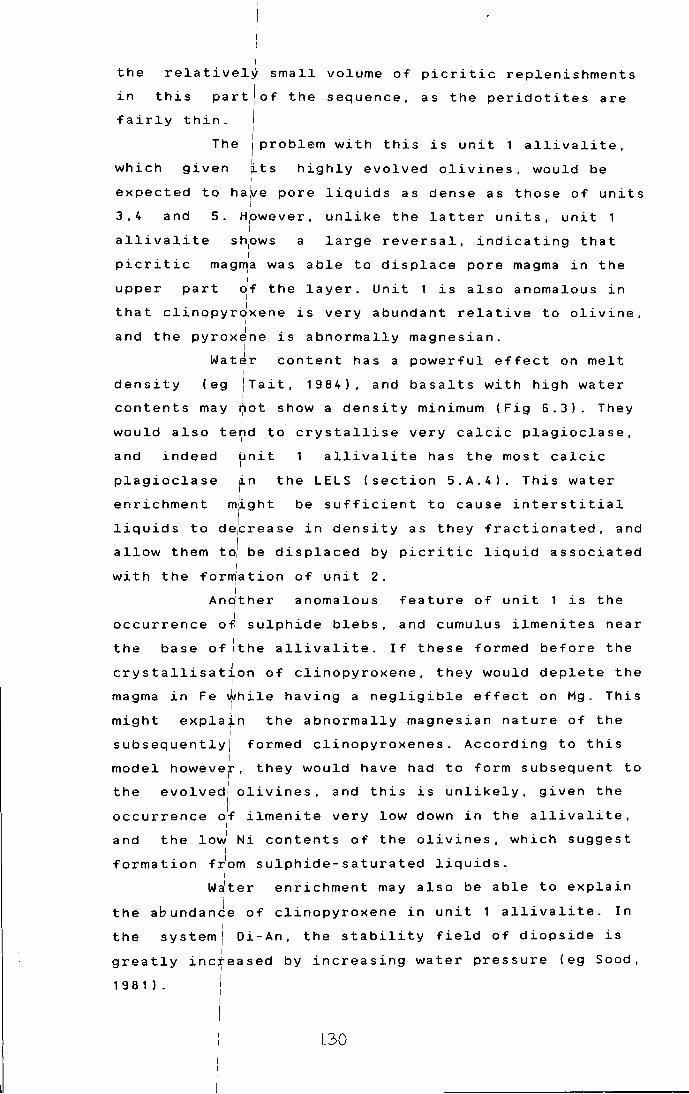
I I
i I
the relatively small volume of picritic replenishments
this part/of the sequence, as the peridotites are in
fairly thin. I I
The /problem with this is unit 1 allivalite,
which given its highly evolved olivines, would be I
expected to ha~e pore liquids as dense as those of units i
3,4 and 5. H~wever, unlike the latter units, unit 1 I
allivalite sh~ws a large reversal, indicating that
picritic mag~a was able to displace pore magma in the I
I upper part df the layer. Unit 1 is also anomalous in
I
that clinopyrdxene is very abundant relative to olivine, I
and the pyrox~ne is abnormally magnesian. I
Water content has a powerful effect on melt I
density (eg
contents may
jTait, 1984), and basalts with high water
~at show a density minimum (Fig 6.3). They I
would also tend to crystallise very calcic plagioclase, I
and indeed Lnit allivalite has the most calcic I
plagioclase in the LELS (section 5.A.4). This water I
enrichment m~ght be sufficient to cause interstitial I
liquids to de~rease in density as they fractionated, and I
allow them t~ be displaced by picritic liquid associated I
with the formation of unit 2. I
I An~ther anomalous feature of unit 1 is the
I • occurrence o~ sulph1de blebs, and cumulus ilmenites near
I
the base of lthe allivalite. If these formed before the I
crystallisation of clinopyroxene, they would deplete the I
magma in Fe ~hile having a negligible effect on Mg. This !
might expla~n the abnormally magnesian nature of the I
subsequently/ formed clinopyroxenes. According to this I
model however. they would have had to form subsequent to
the evolved/ olivines, and this is unlikely, given the I
occurrence o~ ilmenite very low down in the allivalite, I
and the lo~ Ni contents of the olivines, which suggest I
formation f~om sulphide-saturated liquids.
W~ter enrichment may also be able to explain I
the abundande of clinopyroxene in unit 1 allivalite. In I I
the system/ Di-An, the stability field of diopside is I
greatly inc eased by increasing water pressure (eg Sood,
1 9 8 1 ) •
L30
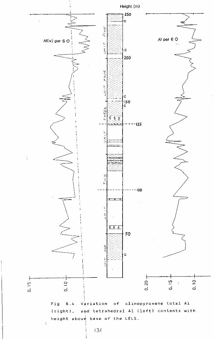
0
I I
I Al(iv) per 6 0 I
Fig
0
0
I I I
6.4
(right),
I I I I
Height (m)
-----,.250 ....... . :· .. ·· .. ·· .. ··. c
~ ><<>: ...............
1..!.. . -::--::--::·· ..
f.-·.:::::>:> ..
< c )f-'-0--'-'--'~
-••• -.-•• -:-:-•• -• • __r. 200
'>! J ....... . Q
\!._ •• • •• ·· •.
~
; :::::::::::::::: c --·-----
ISO 'J.J .• •· .•.... c I.!J "'" .. ·· . .-· .. ·· .. ·· :t s--s-5'--1-- ··. :·. :··. "'.
--- ~~:~:·~ -----125
\--
0
J 1-
2 )
---
-----100
.....,.___ ::-.. -:-:-.-:-:-. .-?. 50
1- ~ ·::··~.<-'Z :J
c
0 N
0
AI per 6 0
V~riation of clinopyroxene total Al I I
0
0
a~d tetrahedral Al (left) contents with I I
height above base of the LELS. I I
131

6.C Variation in clinopyroxene minor elements I I I
I 6.c.1 ALUMINIUM
I
I The variation of clinopyroxene aluminium
! content wit~ height is shown in Fig 6.4. Higher Al
I
contents tendi1
to be associated with peridotites, and the
lowest Al co~tents tend to occur with the most evolved
allivalites. \The latter may be due to the depletion of I
Al in the melt by extensive plagioclase crystallisation, I I
or to higher Tio 2 activity during the formation of these
rocks. Tetrahedrally coordinated aluminium contents are I
a more I
sensitive indicator of silica activity. The I
variation of Al. with height is also shown in Fig 6.4. , ~v
There is a ma~ked decrease in Al. in the allivalites of 1 ~v
units I
3,4 an~ 5, suggesting increasing silica activity
during the for~ation of these rocks. I I I
6.C.2 TITANIUM I
I The \variatio~ in titanium with height is
complex, and generally ~nter-sample variations are of a I
similar order\of magnitude to the standard deviations I
each sample (Fig 6.5). I
for However clinopyroxenes with
high Ti cont~nts (>0.03 per 6 0) are restricted to
peridotites, I
a'nd I I
are associated with fingering and
replacement in the upper part of unit 2 and the lower I
part of unit 3\. Ti does not show a marked decrease in I
the allivalites\of units 3,4 and 5, as might be expected
from the Al. behaviour. However Ti enrichment in the ~v i
liquids from which these fractionated cumulates formed I I
may cancel out I
the effects of increasing silica
activity. i I I I i
6.C.3 CHROMIUM\ I
Intra~sample Cr variation is considerable; for
this reason
contents for
clinopyroxene
fractionation.
clinopyroxene
I the values shown on Fig 6.5 are maximum
I
e\a ch sample. Cr is highly compatible in ' a~d thus should be a good indicator of
I I • : L~ke olivine Fo contents, and I
M~n. the Cr profile shows marked peaks
132

Ti per 6 0
-:T 0
0
Fig 6.5
(right)
LELS.
Nl 01
01 !
Height (m)
-r.-:-~ .. ~ .. ~ 250
·····~-.~-
~::::::::::::::::: ii.. ::::<::::::<::
I::-:::::::::::::::: -:z :J
"' J ....... . 0 ....... . IL
\- : .. ::..:: .. :: .. : ;:: -:: .. :: .. :: .. ::-
c
:J '.,".,".,".,' c ~~~ ,, .. ~,-.. -, 150
l.u c IJ.l ::--:: .. :: .. ::-'0£ ".,".,".," ..
~ }jj'-·--- ~:~:-:~:;;.. -- ---JlS
1-;:-:-·:~
J - .. --.-. '·
0 5 1-
1-
2
:J
1------
1.,----,---n-
----s s 5
~::::::::::::::::
-----100
50
0 ::::::::::::::-;. c 1-~-~ 2 ::>
Cr P per 6 0
-:T 1'0 N 0 0, 0 0
c5 0 0 0
I
I ~ariation of clinopyroxene Ti (left) and Cr
I I :contents with height above base on the I

I associated with peridotites, and troughs associated with
I
allivalites. I Minimum Cr contents are usually seen a I
little way lbelow the top of allivalites; the topmost I
part usuall~ shows a reversal with enrichment in Cr. I
like Mgn valu1es.
I I
6. D Conclusi 1
1ons
( i) I The L EL S s haws more extensive cryptic I
variation than other parts of the Rhum complex. 1
I (ii~ Cryptic variation is generally more
I
I marked in allivalite layers than in peridotites.
I I
Peridotites nearly always have more magnesian olivines I
and clinopyro*enes than adjacent allivalites, supporting I
the idea of p~riodic replen~hment of the magma chamber. I
(iii) The pattern of cryptic variation I I supports the model of Huppert and Sparks (1980) for the I
origin of the large-scale (peridotite/allivalite) I
layering. 1
(iv)\ Post-cumulus processes play an important
role in contr\olling mineral chemistry. Reequilibration
of minerals ~ith migrating pore magmas is often I
significant, ~nd tends to lower the compositional I
contrast betw¢en layers. Subsolidus exchange of Fe and
Mg between
parallelism
!. 0
ol~v1.ne
of\ their ! I I I I
and clinopyroxene accounts for the
cryptic variation patterns.
134.

CHAPTER 7
DISCUSSION AND CONCLUSIONS
7.A. The formatiol of the LELS
As dishussed in chapter 6, the large-scale I
peridotite/allivalite layering can be explained by a
model similar to ~hat of Huppert and Sparks (1980). This I
involves the peridotites crystallising from hot, dense
· · t · 1 I p~cr~ ~c ayers at the base of the magma chamber. The
11. 1. I . . .
a ~va ~tes crystall~se from res~dual liquids
The beh~viour of a picritic layer, and the way
it breaks down is dependent on the temperature and
density contrast between the picritic liquid and that
already in the magma chamber (Sparks et al 1984).
Generally in Rhum the contacts between peridotites and I
overlying allivalites are sharp. This may imply that the
olivines of the plridotite have settled out prior to the
commencement of Jlivine + plagioclase crystallisation.
I th · d · I · 5 · n e per~ ot~te of un~t however, there ~s a
gradational contJct between the two layers, marked by
centimetre-scale layering between olivine-rich and
plagioclase-rich ]ayers, the former becoming thinner and
less well definJd with height (section 3.8.5). This
suggests some oveJ
1
lap in the crystallisation of olivines
in the picritic ]ayer and plag~oclase + ol~v~ne ~n the
magma above. TheJe different contacts can be explained
in terms of diffe~ent temperature and density contrasts
between the picrite and the overlying magma.
In the dase of sharp contacts the settling out
of olivine in t~e picritic layer seems to have been
completed before lthe reappearance of plagioclase as a
cumulus phase. In the case of the gradational contacts
the picritic laye) seems to have broken down before the
olivines had settled out. This could happen if the
densities of the two liquids approached equality before
the temperatures equalised. The thermal gradient might
be sufficient to keep convection going, and keep the
olivines suspended, while cumulus plagioclase
crystallised from the hybrid liquid. The complex zoning
shown by plagioclases in the gradational zone is

I consistent with t~eir having formed
I prior to
emplacement of the picrite, and then continuing to grow
from more basic, rJplenished liquid produced by mixing
of the liquids. I
7. A. 1 Types of smal~-scale In additJon to
lyering
the large-scale layering
d. I 1scussed above. many types of smaller-scale layers
occur. The main typJs are as follows:
( 1. ) A I f ppearance o a cumulus phase. The best
example on Rhum is ~he clinopyroxene rich upper part of
unit 9 allivalite (IYoung and Donaldson. 1985; Palacz.
1984). This merely !indicates progressive evolution of
the magma from whic~ the cumulates are forming.
contacts.
unit 12,
(ii) Chro~ite seams at anorthosite/peridotite
Both the qlassic chromite seam at the base of
and the seam seen in unit 3 truncate lamination :
in the allivalite and seem to have formed by reaction I
between picritic magma and plagioclase. The allivalite I
is thermally eroded (ie resorbed) and coated by a I
reaction crust of chrome-spinel. I
(iii) Variation in grain size. Abrupt changes I
in grain-size generally seem to be associated with I
lensoid, fine-grained plagioclase-rich layers. which it I .
has been suggested (sect1on 3.C.3.a). are deformed I
xenoliths. Other atirupt changes in grain size are seen
in peridotites. paJticularly the minor peridotite high
up in unit 5, wheJe variations in size and habit of
olivines occur. Iridividual laminae may be only one . i . .
crystal th1ck. Desp1te the ev1dence for textural
equilibration it is !likely that these variations reflect
fluctuations in thelgrowth conditions of the olivines.
(iv) Variations in the relative proportions of
intercumulus phase$. This type of layering, termed
matrix banding by ~unham (1965), is best developed in
peridotites where !variations in the proportions of
clinopyroxene and plagioclase are spectacularly picked
out on weathered s~rfaces. In the layered series this
layering is usuallyjsub-parallel to the general dip, but
in peridotite plu.s, I
eg at Sgaorishal, it may be
The typJ example, from a plug north of the
(Dunham ,I colloform.
Long Loch 1965) has been reinterpreted by I McClurg ( 1 9 8 2) as I an early, hydrothermally altered
joint-set, but elsewhere this type of layering certainly I
exists. I
(v) Variations in the abundance of I
intercumulus materi~l. The best examples are the dunite !
layers developed within peridotites of the upper ELS and I
CS. These are prqbably related to the way in which
intercumulus materi~l is expelled from a compacting pile
( McKe~zie, 1985). This is developed on a
scale ~n the peridotites of units 2 and 3
of crystals
very local
(section 3.C.1.a). I
(vi) SliJht variations in the relative
proportions of cumu~us phases. This is almost ubiquitous I
in the LELS allivalites, and widespread elsewhere on I
Rhum.
(vii) I I •
Sed1mentary layering. Layers showing I
unambiguous evidence of sorting by sedimentary processes I
are found in Rhum, !although rarely. In parts of the CS
size and density g~aded ultrabasic breccias are found,
and in unit 9 allivalite on the Askival Plateau, a I
ripple laminated and cross-bedded sequence occurs. There
is some evidence th~t sinking of chrome-spinels, and by
implication, olivin~s. may have been significant in LELS
peridotites (sectiof 3.C.1 .a). However, such evidence is
lacking in LELS allivalites. I
Possible examples of mechanical erosion in the I
LELS cumulates are1
seen in the channel-like layers of '
Unit 3 allivalitej (section 3.8.3), and in unit 5
allivalite, where 1an ilmenite-rich layer truncates
underlying layers I (Fig 3. 9). There is little or no
mineralogical or cr~ptic change across this layer, so an
origin by thermal[ erosion (cf chromite seams) seems
unlikely. I
7.A.2
I ' I I
The origins of small-scale layering
Evidence for the production of small-scale I I
layering by crystali settling and sedimentary sorting is
generally lacking ih the LELS, at least in allivalites. I I
I 137

A variety of altern~tive mechanisms have been proposed, I
the main varieties ~f which are reviewed below.
(i) Kinet~c effects
Maaloe /(1978) argued that rhythmic
supersaturation mig~t be important in producing layering
in Rhum and Skaerdaard. Most phases do not begin to
crystallise at thJir true liquidus temperatures, but I
require some degree lof supercooling and supersaturation
before nucleation land crystal growth can operate I
effectively. He a~gued that this could cause a I
crystallising liquid to oscillate about a cotectic with
cooling, rather tha~ following the equilibrium path. The
products of this o$cillatory path would thus alternate
in composition, p~oducing a layered sequence. Maaloe . I
argued that th~s produced the observed small- scale I
layering within uhit 14 allivalite. The process is
plausible, althoughi in the case of unit 14 the layering I
examined by Maaloe consisted of alternations between I
peridotite and allivalite, and is probably related to
minor replenishment~ of picritic liquid. I
Diffusion 1controlled oscillating
crystallisation isl also a possible mechanism (cf
Leisegang Rings), / but this could only occur in
non-convecting liq~ids where concentration gradients
were able to build ~P above layers of growing crystals.
(ii) Crys~allisation from stratified liquids.
The prod~ction of layered cumulates by
crystallisation f~om layered liquids has been proposed I
(eg Irvine, 1980) •1
As discussed earlier there is good
evidence that the ~eridotite layers can be accounted for
by crystallisatiori from short-lived, dense picritic I
magma layers, howe~er the application of this mechanism
to other types of ~ayering is not clear.
If a dJnsity gradient exists in a magma I
chamber cooled f~om above, or heated from below,
stratification of i the liquid may occur. A density I I
gradient can be induced in various ways. Entrainment of I I
a light, turbulent lboundary layer, produced by sidewall I I
crystallisation, 9r by melting of low-density country I
rocks, is one possibility. An upward increase in water I
138

content of the m~gma might be another. It has been I
suggested that the 1
Margina1 Suite represents, at least
in part, a frozen lsilicic boundary layer to the Rhum
magma chamber; thJs a density gradient caused by I
increasing silica-dontamination with height seeems
likely. H . I
eat 1nput from below, by hot dense picritic I
magma layers, would cause stratification in the magma
overlying the picrite. Whether this stratification would I
persist during crystallisation, and whether it would
produce layered cumJlates is unknown. However one of the I
properties of such !stratification is that density must I
decrease upwards from layer to layer. It seems unlikely !
that the small-sc~le layers seen within allivalites I represent the products of successively less dense liquid I
layers. I
StratificJtion I
as described above, will tend
to break down fro~ the bottom upwards. One possible I
effect of this mig~t be that the magma at the base of I
the chamber wouldj undergo periodic compositional
fluctuations as thelinterfaces between overlying layers
broke down and the ~agmas mixed by convection. Cotectic i .
surfaces in basalt1c
Irvine, 1 9 7 7) . I
Thys
systems are often curved (eg
mixing of liquids at different
points on the cot~ctic can produce "hybrid" liquids I
deviating from cotectic compositions. This would produce I
changes in the cumulates observed. This process in not,
of course. depend~nt on the breakdown of stratified I I
liquids. Any period~city in mixing caused by convection I
in the magma above the growing crystal pile could in I
d 1 I •
theory pro uce ayer1ng.
(iii) Flubtuating water content. I
Phase relations in many silicate systems are
• I · t · t sensit1ve to changef 1n water conten . Increas1ng wa er
pressure in the ~ystem Fo-An-Si02
moves the phase I boundaries towardsl more silica-rich compositions (eg
Sood, 1981), incr~asing the size of the olivine I
stability field in; particular. Thus fluctuating water I
pressure in the m•gma chamber might be sufficient to
produce small
crystallising
I I
charges in the proportions of phases I
on ~ cotectic. The most striking i
139
I I I
compositional I effect of small changes in water content I
of basic melts is dn the composition of crystallising I
plagioclase. Thus I if this process is significant in
producing layering, /variations in plagioclase An content I
should be marked between layers. This has been invoked I
as a possible explanation for the abundance of I
clinopyroxene in uhit 1 allivalite (section 6.8). More I
precise applicatio~ of such explanations on a smaller
scale is difficul~ as plagioclase compositional I
variation seems t~ be somewhat haphazard and difficult .I
to interpret (sect~on 5.A.4). However this very lack of I
correlation between plagioclase An content, and the I I
Fe/Mg ratios of olivine and clinopyroxene, suggests that I I
fluctuating water 1pressure may have been a feature of I the Rhum magma chamber. I I •
In conclus~on, it is very difficult to sort I I •
out the effects of these d~fferent processes. None of I
the above processks are mutually exclusive, and it is . I
l~kely that they1 all play some part. Only rarely can I
end-member proces~es be distinguished, most notably I
layers dominated I by settling and sorting processes. I
Detailed work on ~lagioclases, which unlike other phases I
in Rhum, common~y retain growth zoning, and are I
sensitive to wate~ pressure variations, may provide some I
means of distingu~shing between layers formed by kinetic I
effects and tho~e formed by larger-scale liquid I
compositional variations. i
7 • B • Parental ma~mas, contamination and evolution. I
The ge~eral sequence observed in the LELS
suggests an oli~ine-rich tholeiitic parent, as I
orthopyroxene is :a common phase, and inverted pigeoni te I
has been found iri a xenolith derived from the upper part
of the I
intrusidn. Most of the cumulates are olivine'
hypersthene nor~ative with I
no free quartz. However I
nepheline-normative rocks are also found, mainly as late I
veins
LELS
in perid6tites, and the intercumulus phases in I
peridotite~ suggest formation from late alkaline I I
magmas. j
The e~rliest attempt to determine the I
I I 140
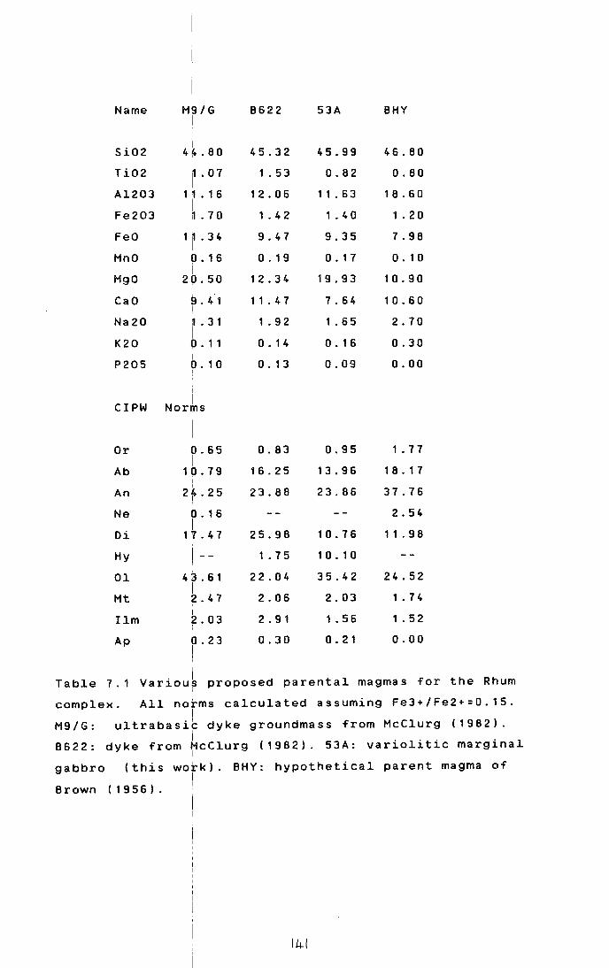
Name
Si02
Ti02
Al203
Fe203
FeO
MnO
MgO
CaO
Na20
K20
P205
CIPW
Or
Ab
An
Ne
Di
Hy
01
Mt
Ilm
Ap
MS/G !
i 4~.80
11 • 0 7
H .16 I '1 . 7 0 '
1 11 • 3 4
0. 16 i
2p.50
9 . 4 1 I l . 3 1 I 0 . 11 I 0. 1 0 !
i Norms
0.65 I
10.79 I I
2f.25
0. 16 I
1 7 . 4 7
I --
4J.61 I 2.47 I ~.03
0.23 I I I
8622
45.32
1 . 53
12.06
1 . 4 2
9.47
0. 19
1 2. 3 4
11 • 4 7
1 • 9 2
0. 14
0. 13
0.83
16.25
23.88
25.98
1 • 7 5
22.04
2.06
2.91
0.30
53 A
45.99
0.82
1 1 . 6 3
1 • 4 0
9.35
0. 17
19.93
7.64
1 . 6 5
0. 1 6
0.09
0.95
13.96
23.86
1 0. 7 6
1 0. 1 0
35.42
2.03
1 • 56
0. 21
BHY
46.80
0.80
18.60
1 . 2 0
7.98
0. 1 0
10.90
1 0. 6 0
2.70
0.30
0.00
1 . 7 7
1 8. 1 7
37.76
2.54
11 . 9 8
24.52
1 • 7 4
1 . 52
0.00
Table 7.1 Variouk proposed parental magmas for the Rhum
complex. All norms calculated assuming Fe3+/Fe2+=0.15.
M9/G: ultrabasib dyke groundmass from McClurg (1982). I
8622: dyke from McClurg (1982). 53A: variolitic marginal I
gabbro (this work). BHY: hypothetical parent magma of I
Brown (1956). I
I 14-1

composition of the parental magma was made by Brown
( 19 56) . He subtracted the relevant quantities of the I
cumulus phases I from the whole-rock analysis of an
allivalite from 1
unit 3, which he assumed to be a perfect
orthocumulate. IThis gave the composition of a highly
aluminous transitional/alkaline basalt. (Table 7.1). I
This method is ~ikely to be highly innacurate in view of
the difficulty! in distinguishing cumulus from I
intercumulus material in allivalites, and in view of the
possibility thJt the liquid finally trapped in the
cumulate was noJ directly related to that from which the I
cumulus phases formed. A further difficulty arises from I
Brown's opticallestimates of mineral compositions, which
for Unit 3 at 11ast, were probably somewhat in error.
Anoth~r approach was used by Tait (1985). He
used analyses lof Rhum ultrabasic dykes from McClurg I
(1982) and Forster (1980) as parent liquids and produced
a convincing model for the chemical evoution of Unit 10.
Analyses of t~e compositions used are given in Table I
7.1. Rocks in t~is dyke suite are transitional: some eg
M9 are nephelinb normative while others such as B622 are I
hypersthene normative. I
It h~d previously been assumed that as the
Rhum ultrabasi~ complex was entirely fault-bounded, it
had no chilled margins. However possible chilled margins
have been idehtified under the low-angle contacts at
Beinn nan Stab and Sgurr nan Gillean. An analysis of I sample 53A from the latter locality is given in Table
7.1. The rock ib similar in chemistry to the ultrabasic I
dykes, but is enriched in Ba and K due to having been I
emplaced agains~ felsites of low melting point.
Thesel picritic and ultrabasic dykes and
marginal rocks ~ould seem to provide good candidates for
mildly alkalin~ or transitional parent magmas. Their
close spatial I and temporal association with a large
ultrabasic magm~ chamber cannot be fortuitous. I I
The n:ext problem is to explain the coexistence I
of tholeiitic ; and alkaline rocks in the same magma I
chamber. Camp~ell (1985), among others, has suggested I
that continen~al tholeiites may be produced by
14-2

I contamination o~ picrites by silicic continental crust.
A similar metho~ may be appropriate to Rhum.
Alkalfne rocks are always associated with I
peridotites in IRhum. According to the model of Huppert I
and Sparks (1980) and Tait (1985), peridotites evolve I
from influxes qf picritic magma which pond at the base
of the magma chJmber. Allivalites crystallise from more I
evolved 'basal~ic' liquids with longer residence times
in the magma chJmber. There is abundant evidence in the I
Marginal Suite for contamination by melted acid country I
rocks. If, as j has been suggested in Chapter 2, the
Marginal Suite tepresents the original igneous margin of
the intrusion,/ the walls of the intrusion would have
been marked bylan upward-convecting boundary layer of I contaminated magma. If convection in this boundary layer I
was turbulent, I then siliceous contaminated magma would I
become incorporated into the main body of the magma I
chamber. I
Th I · h · 1 e ponvect1ve be av1our of boundary ayers
depends on the ~rashof number, G, calculated thus: I
I I
where g =gra v i/ta tiona 1
3 2 G = gdrl /r v
0
acceleration, dr=density
difference, L=v~rtical height of boundary, r =density of I o
magma away fr~m
viscosity of ~he I
the boundary layer and v=kinematic
magma. If G is > 106
then convection
will be turbul~nt. Using - 1 - 1 r =2.7 gem , dr=0.25gcm , and
0 2 2 -1 I v=10 em s , as values applicable to Rhum, convection
I be turbJlent for wall heights greater than about
I would
It is ~hus likely that convection was turbulent I
103
em.
and contaminat~on would have been carried into the main
body of magma~ For a rhyolitic magma chamber, Spera et
al (1982) ca~culated the thickness of the convecting
boundary layer/to be about 100m.
It ~ight be thought that the close proximity • I
to the Marg1na~ Suite of apparently undisturbed layering I
argues agains~ such a boundary layer. However vertical I
convecting boundary layers have sharp contacts, I
particularly in their lower portions where flow may be I laminar. Huppert and Turner (1980) illustrate double-1
I 143 I

I I I
diffusive liquid stratification stably coexisting with a I
thin turbulent boundary layer in the case of ice-blocks I
melting into a salinity gradient. I
The ~xact behaviour of the boundary layer in I
Rhum would be m~ch more difficult to analyse, due to the I
lithological a~d thermal complexity of the boundary. I
Factors which would have to be considered include the i
viscosity, temperature and density profiles across the I
country rock -1 melted country rock - chilled margin -I
magma zone, th~ rate of formation and rupturing of the . • I
ch~lled marg~n 1 , and the style of convection and heat
transfer occur~ing with in the main body of magma. The I
thermal budget pf the intrusion would also be important. I
Replenishment Olf the chamber would maintain it at a very I
high temperat~re; the crystallisation of large I
quantities of ~livine would release enormous quantities
of latent heat /which would encourage thermal erosion of
the wall I rocks .1
This may have been a major mechanism in I
creating spac~ for the ultrabasic chamber, with the I
melted country rocks being convected upwards along the I
intrusion walls and erupted out of the top of the I
volcano. I
The partial entrainment of the contaminated
boundary layer1into the main body of magma could well be
sufficient to tause initially alkaline basalts to evolve I I
along a thole~itic path. Thus according to this model . I.
picritic l~qu~ds entering the chamber may have been I
mildly alkalinr, but liquids residing in the chamber for
any length of ~ime would be tholeiitic.
This/ still leaves the problem of early
intercumulus o~thopyroxene in the LELS peridotites. This
could be ex~lained by downward percolation of
contaminated /tholeiitic liquids into the crystal ~ile; but orthopyrQxene occurrences do not correlate w~th
I other evidencl for downward movement of evolved liquids
(chapter 5). : I
It ~s suggested that the orthopyroxene is the I
of mixing of the incoming picritic pulse with I
result I I
contaminated +iquids in the magma chamber. Depending on I
the density c6ntrast between the incoming magma and that
144
I I I I I I I
I I
in the chamber, and the velocity and direction of i
intrusion, t~e ~ncoming magma may form a turbulent plume I
as it enters th~ chamber. This would entrain appreciable I
quantities of t~e old magma before sinking back to form I
a layer at th~ base of the chamber. This could result
in the perid~tite becoming silica-saturated, and
crystallising !orthopyroxene. The ins ta bili ty of I
orthopyroxene lin peridotites suggests that later
alkaline picrJtic liquids were able to percolate into
the crystal pi~e. without being contaminated, giving the I
alkaline trends commonly found in peridotite I
intercumulus assemblages. I I
Apar~ from the LELS, and to a lesser extent,
Unit A of the ~LS, orthopyroxene is very rare or absent I
in the the ultrabasic complex. This may partly be I
related to t~e proximity of these areas to vertical I contacts wher~ turbulent boundary layers would be most I
likely. Another possibility is that contaminated silicic I
magmas did not accumulate in the chamber during the I
formation of /most of the complex. More frequent and
larger influxe~ of magma might explain this, as residual I
magmas were fl~shed out before significant contamination i
could build upi. Another possibilty is the development of I
a more stable/ chilled margin during the development of
the upper EL~. which may have acted as a barrier to
1 a r g e - s c a 1 e c:o n t ami n a t ion . A f u r the r fa c tor m a y h a v e I
been a change in the convective regime in the magma i
chamber, such :that contaminated liquids were not present
in the lower /part of the chamber, where the cumulates • I were form~ng .
1 A stable liquid stratification might
I confine large~scale entrainment of contaminated liquids
I to the upper part of the chamber.
I I I
7.C. Fingers/and replacement
Fin~er structures provide clear evidence for I
replacement of allivalite by peridotite in the Rhum I complex (Butcher et al, 1985). A brief outline of their
. . I . . ma~n features, ~s g~ven below.
I ( i) I Finger structures post-date the
I development of lamination, and slump-folds in the
I
I 14-S" I

I I I I I I
overlying allivalite.; However they are earlier than the
late-stage veins, Jhich have been observed to cut
fingers.
( ii)
I I I I I
Fing~r structures are only seen on the I
upper surfaces of peridotite layers. Where peridotite
overlies I
allivalite! I I
contacts are either sharp and
planar, or show deformational structures such as flames
and load-casts. I I I I
(iii) Fing~rs occur on a range of scales from I
< 1 em . up to 1m or/ more where they cut right through I
allivalite layers. I~ the most extreme examples, only a I I
few relict blocks of allivalite may be left, scattered I
along strike. It lis thus possible that fingering I have completely removed allivalite horizons, I
processes I
leaving no trace of /them. I
(iv) Deformation associated with fingers is
negligible compared/with the scale on which they occur.
Allivalite fingers generally shows no I
adjacenr to
evidence of deforma~ion, although in specimens from unit I
8, single plagioclase crystals are deflected upwards I
against the finger margin. I
Elongate olivines w~thin the
peridotite of the /same finger are aligned parallel to I
the finger margins', suggesting that the allivalite was I I
behaving more rigi91Y than the peridotite.
( v) Fin~ers only seem to be associated with I
troctolitic or a~orthositic allivalites. Allivalites I
rich
This
only
in pyroxene h~ve not been observed cut by fingers. I
may suggest/that the fingering process operates
·I · t · 1 over a restr~~ted compos~ ~ona range. I
(vi) The~e in little relationship between the I I
thickness of a pe~idotite layer and the amplitude of the I
fingers along its :upper surface, although fingers on the I
upper surfaces dn load-casts and other semi-isolated I I
masses of peridot~te are always small. I
(vii) The Mg/Fe ratios of olivine and I
clinopyroxene sh6w no significant differences between I I
finger peridotite: and adjacent allivalite.
7. c. 1
I I
I I
• • I o~scuss~on:
I
While the morphology of finger structures I I
! \4-b i

I I I I I I
suggests an origin b~ loading (cf Anketell et al, 1971), I
the lack of deformat~on in the cumulates argues against I
this. It has been suggested that the interstitial liquid I
in peridotites may : be less dense than that in I
allivalites (Butchet et al 1985). Thus liquid-liquid I
loading could occut within the interstices of the I
crystal pile. According to this model, peridotite pore I I
liquid may not be in equilibrium with plagioclase, and I I
would tend to resorb/ it, crystallising olivine. However, I
large fingers occur ~bove thin peridotite layers, and it I
it doubtful that suf~icient pore liquid would be present I
to resorb significa1t quantities of plagioclase.
A possibl~ solution to this is provided by the I
evidence for late-s~age alkaline liquids in peridotites. I
This has been used Ito argue for replenishment of pore '
• ,I
liquid in per~dot~tes by primitive, undersaturated I I
liquids (section 7.8). That evidence for such I
replenishment is l+cking in allivalites is ascribed to I
their low permeab}ity, perhaps due to more efficient I
packing of tabular plagioclase compared with the rounded I
or irregular shape~ of olivines in peridotites. In the !
LELS, those parts/ of the sequence where fingers are I
developed have hig~ Ti contents in clinopyroxenes, one I
of the features of /pore liquid replenishment. I
It is thJs proposed that the peridotites were I
often able to act ~s permeable "aquifer" horizons, along I
which primitive lfquids were able to migrate. This is I
perhaps not a requisite.of replacement, but replacement I I •
large scale;requ~res replenishment of the pore on a I
liquid. Where peridotite may I I
be cut off from
replenishing liqu~d as in load casts, the fingers are I
always small. :
The res~riction of fingers to the upper I
surfaces of perido~ites may involve a number of factors. I
First, during com~action of a sequence of several units, I
pore liquid expel~ed from the lower parts of peridotites I
may tend to become ponded below less permeable I
allivalite layers) producing melt-supported layers which I
• I would be h~ghly permeable. Second, the liquids involved
I I
in resorbing all+valites may be lighter than the pore
I 14-7
' liquids in a11iva1~tes affected by replacement. Thus I
where these liquids ~ver1ie allivalite, they would have I
1i t t1e tendency to I penetrate into it. Another I
possibility is that while fingers are produced by I I
replacement in sityations where allivalite overlies I
peridotite, in other/situations replacement may produce I
contacts with differ~nt morphologies. If planar contacts I I
can be produced by r~p1acement, then the phenomenon may I
be extremely widespread, but its effects may not be I
recognisable. I
7 • D •
has
ELS,
I I I
I Evolution of ~he u1trabasic complex
I
As discu~sed in chapter 1, the Rhum complex
been divided ~nto 3 main lithological units: the ' I
WLS and CS. \he CS is the latest-formed and has I
subsided into its present position. This obscures the I I
relationship betwe~n the ELS and WLS. Further I
difficulties are in~roduced by movements along the Long I
Loch Fault. Some of this is later then the emplacement I
of the CS, but it h~s been suggested that the fault was I I
active before thils ( Eme1eus et a1, 1985) and I
differential move~ent of the ELS and WLS may have I
occured before emplacement of the CS. Thus it is not I
known whether the ELS and WLS represent different facies I
in the magma ch~mber developing simultaneously, or
whether I
one is older than the other. At present it is I
not possible to r~so1ve this problem directly. However I I
there are certain/ similarities between the ELS and the I · 1 t. WLS. Both are character~sed by a genera reverse cryp ~c I
variation. The HI •
1arr~s Bay member, like the LELS,
consists of re1a~ively evolved rocks. Further up the I
sequence both th~ WLS and the ELS tend to become more I
"u1trabasic" wit~ more magnesian olivines and the
development of o~ivine-rich harrisites, although these I
are fairly rare i~ the ELS. '
If thi~ implies at least a partial temporal I
overlap between ithe two series, then conditions must
have been extremely variable over quite short distances I I
in the magma chamber. Plagioclase rich rocks are not I I
seen in the WLS, 1 implying that mag rna s with p1agioc1a s e
I ILL '3 I I
I
on the liquidus were never able to crystallise in the I western part of the chamber. I
Other evidence can be used to argue for the I !
WLS having a lower stratigraphic position than the ELS. I
The WLS is bounded by the Western Granophyre, while the I
ELS is in contact w~th higher level rocks - felsites, I I
explosion breccias : and amygdaloidal basalts (seen as I
xenoliths). Whether! this relative disposition of early I
Tertiary acid roc~s occurred before or after the I I
development of the ~LS and WLS is uncertain.
! 7. E. Emplacement of the complex
I
The intetpretation of the low-angle contacts I
under Beinn nan Stac, Cnapan Breaca and Sgurr nan I I
Gillean, as fragm~nts of the roof to the ultrabasic I
magma chamber has1 important implications for the I
emplacement of the/ complex ( Emeleus et al, 1985). The I I
interpretation of the vertical marginal contacts as also
being
complex
I
original i~neous contacts means that the Rhum I
is essenti~lly in situ. I I
This ea~es some of the problems associated I
with the model df Emeleus et al (1985). These are I
principally the la¢k of evidence for faulting associated I I
with the Marginal ~uite and the evidence that the magma I
chamber was in contact with hydrothermally altered I I
basalts ( ie very/ high level rocks), and largely I
contaminated by ~arly Tertiary felsite rather than I
deeper seated cou~try rocks. In addition the model of
Emeleus et al ci1985) recognises difficulties in I
envisaging a mech~nism by which a semi-solid cylinder of I I
dense ultrabasic tacks could be emplaced upwards to the I I
present level. 1
I
It is suggested that final uplift along the I I
Inner Ring Fault (Smith, 1985) preceded the development
of the ultrabasih magma chamber. This uplift may have !
been related to ~he entry, at lower crustal levels, of I
large volumes of ~ery hot picritic liquids. Later these I •
magmas were abl~ to reach high crustal levels, form1ng
the Rhum I I· ultrabas11c
I I I I I I
I '
complex we now see.

! I I
An k e t e 11 , \J . M . , C e g 1 a , J . a n d D z u 1 y n s k i , S . 1 9 7 0 . 0 n the
defor~ational structures in systems with reversed I
dedns~ty gradients. Annales de la Societe I .
Geolog~que de Pologne val 40, p3-30. I Bailey, E~B. 1945. Tertiary igneous tectonics of Rhum. I
Quarterly Journal of the Geological Society of I
Londoh val. 100, p165- 191. !
Barnes S.Jl and Naldrett A.J. 1985. Geochemistry of the I
J-M (Howland) Reef of the Stillwater Complex,
MinneJpolis Adit Area. I. Sulphide Chemistry and I
Sulphide-Olivine equilibrium. Economic Geology val I
80, pGI27-645.
Bevan, J.O. 1982. Reaction rims of orthopyroxene and • I
plag~~clase around chrome-spinels in olivine from
Rhum ~nd Skye. Contributions to Mineralogy and
Petrol:ogy val. 79, p124- 129.
Black, G. pl. 1952. The Tertiary Volcanic Succession of I
the Is!e of Rhum, Inverness-shire. Transactions of I
the Ed~nburgh Geological Society val 15, p39-51. I
Black, G.Pf and Welsh, W. 1961. The Torridonian I
succesion of the Isle of Rhum. Geological Magazine I
val 98] p265-276. I
Boctor, N.Z. 1980. Partitioning of Ni between olivine i
and i~on monosulphide melt. Carnegie Institution I
Washington Yearbook 80, p352-356. I
Boctor, N.Z. 1982. The effect of f(O), f(S) and I
temper~ture on Ni partitioning between olivine and I
iron !sulphide melts. Carnegie Institution I
W a shin glt on Yearbook 8 1 , p 3 6 6- 3 6 9 . I •
Brooks, C. K1
• 1976. The Fe203/ FeO rat~o of basalt
analyse~ - an appeal for a standardised procedure.
Bulletih of the Geological Society of Denmark val I
25, p11~-120. I
Brown, G.M.I1956 The layered ultrabasic rocks of Rhum,
Inner \Hebrides, Scotland. Philosophical I
Transactions of the Royal Society of London. B. i
' val. 240, pl - 53. I
Brown, G. M. ! 19 7 2 P igeoni tic pyroxenes - a review.
Memoirs of the Geological Society of America val
ISO
1 3 2 , !P 5 2 3 - 5 3 4 .
Butcher. AI. R. 1984 A study of postcumulus structures
the ~hum layered intrusion, Inner Hebrides,
Scotlbnd. Unpublished PhD thesis, University of
Manchrster.
in
Butcher, A.R. 1985 I
Channelled metasomatism in Rhum
layer~d cumulates - evidence from late-stage veins. I
Geolo$ical Magazine vol. 122 p503-518.
Butcher, A. R •• Young, I.M. and Faithfull, J.W. 1985.
F. I 1.nge~
I structures in the Rhum complex. Geological
Magazine vol. 122 p491-502. I
Campbell, I. H. 1985. The difference I
between oceanic and
continental I
tholeiites: a fluid dynamic
explanation. Contributions to Mineralogy and I
Petro~ogy vol 91, p37-43.
Campbell, II.H. and Turner, J.S. 1986. The influence of
visco~ity on fountains in magma chambers. Journal
of Pe~rology vol27, p1-30. . I .
Cra1.g, J.R.I and Kl.llerud, G. 1969 Phase relations in the
Cu-Fe-1
Ni-S system and their application to I
magmat~c ore deposits. In H. D. B. Wilson (Ed),
Magmat~c Ore Deposits, Economic Geology Monograph
4, p34:4-358.
Craig, J.RI. and Scott, S.D. 1974. Sulphide Phase I
Equilibria. In Ribbe, P.H. (Ed), Sulphide I
Mineralogy, Mineralogical Society of America
Reviewk in Mineralogy Vol 1, pCS1-CS109. I
Deer, W.A. _. ~ Howie, R.A., and Zussman, J. 1978. Rock I
Formin9 Minerals vol 2A, Single Chain Silicates.
Longma~s. London, pp668.
Donaldson, lc.H. 1976 An experimental investigation of
olivinJ morphology. Contributions to Mineralogy and I Petrology vol.57, p187 - 213.
Donaldson, \c.H. 1982. Origin of some of the Rhum
harrisite by segregation of intercumulus liquid. I
Minera~ogical Magazine vol 45, p201-209. I
Donnellan, IN.C.B. 1981. Geochemical Studies of the
Duke,
' I Torriddnian Sediments of N.W. Scotland. Unpublished
' I Ph.D. ~hesis, University of Birmingham.
J.M. 1976 Distribution of the period four
15" I

transition elements among olivine, calcic
1. I
c ~nopyroxene and mafic silicate liquids: I
experimental results. Journal of Petrology vol.17,
p499 J 521.
Duke, J.M .. 1 and Naldrett A.J. 1978. A numerical model of I
the ~ractionation of olivine and molten sulphide
from komatiite magma. Earth and Planetary Science
Lettens vol 39, p256-266.
Dunham, A.C. 1962. The petrology and structure of the
northern edge of the Tertiary igneous complex of
Rhum ·I Unpublished D. Phil. thesis, Oxford
Univerlsity.
Dunham, A.O. 1964. A petrographic and geochemical study
of Jack-veining and hybridisation at a
gabbr~-felsite contact in Caire Dubh, Rhum,
Inverness-shire. Mineralogical Magazine vol 33,
p887-902.
Dunham, A.C. 1965. A new type of banding in ultrabasic
rocks from central Rhum, Invernesshire, Scotland.
American Mineralogist vol 50, p 1410-1420.
Dunham, A.C. 1968. The felsites, granophyre, explosion
breccias and tuffisites of the north-eastern margin
of the Tertiary
Inver nle s s- shire .
igneous complex of Rhum,
Quarterly Journal of the
Geological Society of London vol 123, p327-352.
Dunham, A.1
c. and Emeleus, C.H: 1967. The T~rtiary
Geolog¥ of Rhum, Inner Hebr1des. Proceed1ngs of the
Geologlsts' Association val 78, p391-456.
Dunham, A.CI. and Wadsworth, W.J. 1978. Cryptic variation
in the Rhum layered intrusion. Mineralogical
Magazihe vol.42, p347 - 356. I
Dunham, A.f. and Wilkinson, F.C.F. 1985. Sulphide
Droplefs and the Unit 11/12 chromite band, Rhum: a
mineralogical study. Geological Magazine vol 122, I
p539-548.
Dyson, D.J. and Juckes, L.M. 1972. A silica deficient
pyroxere from iron-ore sinters. Mineralogical I
Magazine val 38, p872-877.
Em e 1 e u s , C 11
• H . 1 9 8 1 . A t h r u s t fa u 1 t a t We 1 s h m a n ' s Roc k .
Isle bf Rhum. Scottish Journal of Geology vol 17, I
lSl

p1-6. I Emeleus, C.t:f. 1985. The Tertiary lavas and sediments of I
northwest Rhum, I
Inner Hebrides. Geological Magazine
vol 12?. p 419-437. I Emeleus, c.r. and Forster, R.M. 1979. Field Guide to the
Tertiary Igneous Rocks of Rhum, Inner Hebrides. I I Newbury. Nature Conservancy Council. I Emeleus, Ci.H., Wadsworth, W.J., and Smith, N.J. 1985.
The early igneous and tectonic history of the Rhum . I .
Tert1ary Volcan1c Centre. Geological Magazine vol I
122, Pf51-457.
Faithfull,
Rhum.
Forster M
D.W. 1985 The Lower Eastern Layered Series of
G
l • .
eolog1cal Magaz1ne vol 122, p459-468. ! ll creo.clu!•mrcc.f c;,.&., Peft-t~cht!'t'''". u:t r lvJ'f 1J ~Ju -r~/ fig"1 ,...; nor lnf'rvr,~.r 4 Ru&J,.,,
1 ~ 8 0 tv .w· )c.flo•J· P~ b Thai,-, (J,10·.,. /}- !J",h~~ ( Vnp•pl;rh<>,i)
Geikie, Sit A. 1897. The Ancient Volcanoes of Great
Britaih. Vol 2. London: Macmillan. I
Gibb, F. 1976. Ultrabasic rocks of Rhum and Skye: the I
naturej of the parent magma. Journal of the
G eo 1 o g 'i c a 1 S o c i e t y o f L on d on v o 1 . 1 3 2 . p 2 0 9 - 2 2 2 . I
Harker, A.l 1908. The geology of the Small Isles of I
Invern~ssshire. Memoir of the Geological Survey of
S cot 1 a In d . 2 1 0 p p .
Henderson. 1P. 1975. Reaction trends of chrome-spinel on I
Rhum. IGeochimica et Cosmochimica Acta vol.39, p1039
- 1 0 4 41. I
Henderson. i P. 1982. Inorganic Geochemistry. Pergamon.
Oxford. 353pp.
Henderson, lp_ and Suddaby, P. 1971. Nature and origin of I
the qhrome-spinel of Rhum. Contributions to
MinerJlogy and Petrology vol.33, p21 - 31. I
Hucke n h o 1 z .1
H . G . . S c h a ire r . J . F . . and Yoder , H . S . 1 9 6 7 .
Synth~sis and Stabilty of Ferri-diopside. Carnegie
Institution Washington Year Book 66, p 335-347. I . . .
Hughes. C .• J. 19 60. An occurrence of t1lley1 te-bear1ng I
limestone in the Isle of Rhum. Quarterly Journal of
the GJological Society of London vol 97, p384-388. I
Huppert, liJ.E. and Sparks, R.S.J. 1980. The fluid I
' dynam~cs of a basaltic magma chamber replenished by
I influ* of hot, dense, ultrabasic liquid.
I
Contributions to Mineralogy and Petrology vol.75,
153

I I I I I I I I
p279 -1289. I
Huppert, H.E. and Turner, J.S. 1980. Ice blocks melting I
into ~ salinity gradient. Journal of Fluid I
Mechanics vol 100, p367-384. I
Irvine, T .Nl 1977. Chromite crystallisation in the join I
Mg2SiO~-CaMgSi206-CaAl2Si208-MgCr204-Si02. Carnegie I
Instit~tion Washington Year Book 76, p465-472. I
Irvine. T. N. 1980. Magmatic infiltration metasomatism, I I
double~ diffusive fractional crystallisation and I
adcumu~us growth in the Muskox intrusion and other I
layer e:d in t r us ions . I n H a r graves , R . B . ( e d ) . The I
Physi~s of Magmatic Processes. Princeton. 585pp. I
Kitchen, D./E. 1985. The parental magma on Rhum: evidence I
from /alkaline segregations and veins in the I
peridotites from Salisbury's Dam. Geological I I
Magaz~ne vol 122, p 529-537. I
Leake, BJE 1978. Nomenclature of amphiboles. I I
Miner~logical Magazine vol 42, p533-63. I
Le Bas. ~. J. 1962. The role of Aluminium in igneous
Le
I
pyrox~nes with relation to their parentage.
Ameripan Journal of Science vol 260, p267-288. . I
MaJ.trel, R.W. 1982. Numerical Petrology. Elsevier. I I
Amste~dam. pp281. I
Maaloe, s/. 1978. The origin of rhythmic layering.
Mine~alogical Magazine, vol 42, p 337-345. I I Marshall, 1L. A. and Sparks, R. S. J. 1984. Origins of some I
mixed- magma and net-veined ring intrusions. i
Journal of the Geological Society of London, vol I
141, /p171-182. I
McBirney, /A.R. and Noyes, R.M. 1978. Crystallisation and I
layering of the Skaergaard intrusion. Journal of I
Petr9logy vol.20, p487 - 554. I
McClurg, 1 J.E. 1982. Geology and structure of the I
nort~ern part of the Rhum ultrabasic complex. I
Unpublished PhD thesis, University of Edinburgh. I
McKenzie./ D.P. 19 85. The generation and compaction of I
par~ially molten rock. Journal of Petrology vol 25, I
p713;-765. I
Obata, M., Banno, S .. ar~d Mori, T. 1974. The I I
iron-magnesium partitioning between naturally I
I

occurring coexisting olivine and Ca-rich . I .
cl1nopy~oxene: an appl1cation of the simple mixture
model to olivine solid solution. Bulletin Societe
f . I . .
ranca1se M1neralog1e et Cristallographie val 97, I
p101-10~.
Palacz, Z. A. 1984. Isotopic and geochemical evidence for
the evolution of a cyclic unit in the Rhum . t . I 1n rus1on, north-west Scotland. Nature vol.307,
p618 - 620.
Palacz, Z. A., and Tait, S.R. 1985. Isotopic and
geochemical investigation of unit 10 from the
Eastern Layered Series of the Rhum Intrusion,
Northwest Scotland. Geological Magazine val 122,
p485-490.
Powell, M. • and Powell, R. 1974. An
olivine-clinopyroxene geothermometer. Contributions
to Mineralogy and Petrology val 48, p249-263.
Rajamani, V. and Naldrett, A.J. 1978. Partitioning of
Fe,Co,Ni and Cu between sulphide liquid and
basaltic melts and the composition of Ni-Cu
sulphide deposits. Economic Geology val 73, p82-93.
Robins, 8. 19
1
82. Finger Structures in the Lille Kufjord
Layered Intrusion, Finnmark, Northern Norway.
Contributions to Mineralogy and Petrology val 81,
p290-295.
Simkin, T. and Smith, J.V. 1970. Minor-element
distribu~ion in olivine, Journal of Geology val 78,
p304-325.
Smith, N.J. 1985. The age and structural setting of
limestones I
southeast Rhum.
and basalts on the Main Ring Fault in
Geological Magazine val 122,
p4 3 9-4 4 51.
Smith, R. K. knd Lofgren, G. E. 1983. An analytical and
experime~tal study of zoning in plagioclase. Lithos I
Sood,
val 16, p153-168.
M., K ·11981 Modern Igneous Petrology. Wiley. New
York. 24tpp.
Sparks, R.S.Jl, and Huppert, H.E. 1984. Density changes I
I during the fractional crystallisation of basaltic
I
magmas: lfluid dynamic implications. Contributions
ISS

to Minerhlogy and Petrology val 85, p300-309. j
Sparks, R.S.J., Huppert, H.E., Kerr, R.C., McKenzie, I
D.P. andl Tait, S.R. 1985. Postcumulus processes in
layered ~ntrusions. Geological Magazine val 122, p I
Speidel, D. HI. and Osborn, E. F. 1967. Element
distribu~ion among coexisting phases in the system
Mg0-Feo-re2
o3-sio
2 as a function of temperature and
oxygen ~ugacity. American Mineralogist val 52,
p 1 1 3 9 - 1 1 15 2 .
Spera, F.J .. / Yuen, D.A., and Kirschvink, S.J. 1982.
Thermal ~oundary Layer Convection in Silicic Magma
Chambers;. Journal of Geophysical Research (B), val
8 7 . p 8 7 515- 8 7 6 7 .
S t a 1 per , E . Ian d W a 1 k e r , D . 1 9 8 0 . Me 1 t density and the I
average 1 composition of basalt. Contributions to
MineralJgy and Petrology vol.74, p7 - 12. I
Tait, S.R. 11984. Fluid dynamical processes in the
formatidn of layered igneous rocks. Unpublished PhD I
thesis, jUniversity of Cambridge.
Tait, S.R. 1~85. Fluid dynamic and chemical evolution of I
cyclic junit 10, Rhum, Eastern Layered Series.
Geologidal Magazine val 122, p469-484.
Tait, S.R .. /Huppert, H.E. and Sparks, R.S.J. 1984. The
role of compositional convection in the formation I .
of adcu~ulate rocks. L1thos vol.17, p139 - 146.
Taylor, S.R.I and McClennan, S.M. 1985. The continental I
crust: 1
its composition and evolution. Blackwell.
Oxford. I pp312. I
Thy, P. and Esbenson, K.H. 1982. Origin of fine-grained I
granulat rocks in layered intrusions. Geological
Magazin~ val 119, p405-412. I 57 3+
Virgo, D. 1972 Fe Mossbauer Analyses of Fe
Clinopy}oxenes. Carnegie Institution Year Book 71: I I
Washington. p534-538.
Volker. J.A~ 1983. The Geology of the Trallval area, I
Rhum, Inner Hebrides. Unpublished PhD thesis,
Univers~ty of Edinburgh. I
Wad swart h , W [. J . 1 9 6 1 . T he u 1 t r a b a s i c rack s a f s au t h -we s t I
Rhum. Philosophical Transactions of the Royal I I
Society: val 8224. p21-64. I I I
ISG
I I I I I I
Wager, L.R. land Brown, G.M. 1951. A note on rhythmic I
layering! in the ultrabasic rocks of Rhum. I
GeologicJl Magazine val 88, p166-168. I
Wager, L.R., 1 Brown, G.M., and Wadsworth, W.J. 1961. I
Types
val 1,
Williams,
of igneous I I
p(3-85. I
C.T. 1978. I
cumulates. Journal of Petrology
Uranium-Enriched Minerals in
Mesostasts Areas of the Rhum Layered Pluton. I
Contributions to Mineralogy and Petrology val 66, I
p29-39. I
Williams, P.~. 1985. Pyroclastic rocks in the Cnapan I
Breaca f~lsite, Rhum. Geological Magazine val 122, I
p 4 4 7-4 510. I
Young, I.M. 1~84. Mixing of supernatant and interstitial
fluids Jn the Rhum layered intrusion. Mineralogical I
Magazin~ val 48, p345-350. I I Young, I. M. 1 1984. The evolution of layered plutons -I
evidenc~ from small scale structures. Unpublished I
PhD the~is, University of St. Andrews. I
I You n g , I. M. ,1
a n d Do n a 1 d s on , C . H . 1 9 8 5 . Form a t ion o f I
granulaF textured layers and laminae within the I
Rhum crystal pile. Geological Magazine val 122, I I
p519-52~.
I Wood, B. J. 1 1 9 7 6. An ali vine- clinopyroxene
I
geothermometer. Contribution$ to Mineralogy and I I
Petrolo~y vol.56, p297 - 303.
157

I I I
/ Acknowledgements
This work was/carried out under N.E.R.C. grant No.GT4 80 I
GS25, at Durham University. Thanks are due to Dr. C.H. I
Emeleus, whol supervised the project, and provided much I
helpful advic~ and support, and to Dr. A. Peckett. Alan I
Butcher, Iaih Young, Johannes Volker, Steve Tait and
Richard Greehwood helped in discussing many aspects of I
the work. Jan~t Mclurg kindly allowed the use of some of I her data. DaMe Plant, Tim Hopkins and Richard Pattrick I
helped me u~dertake electron-probe analysis at I
Manchester U~iversity.
ThJnks are due to the Nature Conservancy I
Council for :allowing the removal of yet more fragments
of the Isle qf Rhum. Numerous people helped me during my
stay on the lisland; particular thanks are extended to I
Peter Duncan~ Peter Hancock, Dave Millar, Pam and Angus I
Mcintosh, and Laughton Johnson.
FiJally I would like I
k . e.
to than Le1sster
University Geology Department for I
allowing me time to
complete this work, and Ms Cathryn Burge for moral
support, andlassistance with typing. I I
I 5 'a
APPENDIX 1
Two sets of standards were used for the
determination or major and trace elements in this work.
A set of ultrabasic and basaltic compositions, I
comprising both international standards and Edinburgh
University int~rnal standards were used for the major
element determihations. The latter (names prefixed by MO
) · 11 . G . tt or RE were k1nd y suppl1ed by . F1 on. I Standards used for trace-element analysis were
internatio~al standards, covering a wide range of all
· · I t t · compos1t1ons and trace-element concen ra 1ons.
Valuek determined for both sets of standards,
together with
overleaf.
the recommended
IS9
values, are given

I DENT SI02 AL203 FE203 MGO CAO NA20 K20 TI02 MNO P205 TOTAL M01
MEASURED 43.80 11.80 14 . 56 11 . 4 9 11 . 3 3 2.49 1 . 3 6 2.95 0. 19 0.53 100.52 TRUE 4 3 . 21 11 . 7 7 1 4 . 4 9 11 . 3 9 11 . 2 6 2.69 1. 4 7 2.90 0. 19 0.60 DIFF 0.36 -0.03 -0.00 0.04 0.02 -0.21 -0. 1 2 0.03 0.00 -0.07
2 RE60 MEASURED 45.75 11 . 0 1 12. 7 5 1 7 . 6 7 8.49 1 . 7 1 0.48 1.72 0. 17 0.22 99.98 TRUE. 45.86 10.37 1 2. 56 18.53 8.27 1 . 8 0 0.50 1.76 0. 1 8 0. 1 8 DIFF -0. 1 0 0.64 0. 19 -0.85 0.23 -0.09 -0.02 -0.04 -0.01 0.04
- -3- -MY5-4----------~ ----- ~- -- ---~ - --- - ------- --- -------- ~-- ~ ---- ----- -------MEASURED 41. 85 15.47 11.44 6. 1 7 1 2. 8 4 6.52 2.25 2.53 0.23 0.92 100.24 TRUE 40.97 16.03 11 . 8 9 6.46 12.24 6.34 2.32 2.68 0.25 0.82 DIFF 0.78 -0.59 -.0.47 -0.30 0.57 0. 1 6 -0.07 -0. 15 -0.02 0. 1 0
-IJ"' 3 NIMP 0
MEASURED 50.91 4.72 12.24 27.45 3.00 0.45 0.09 0.22 0.24 0.04 99.34 TRUE 52.75 4.32 1 3. 11 26. 15 2.75 0.38 0.09 0.22 0.20 0.02 DIFF - 1 . 51 0.43 -0.79 1 . 4 8 0.27 0.07 -0.00 0.00 0.04 0.02
6 M024 MEASURED 45.81 13.66 14.7 2 7.59 10.57 3.32 1. 06 3.06 0.21 0.65 100.65 TRUE 44.56 1 3 . 8 6 1 4. 52 7. 74 10.80 3.45 1 . 1 0 3.02 0. 21 0.72 DIFF 0.95 -0.29 0. 11 -0.20 -0.30 -0. 15 -0.05 0.02 0.00 -0.07
7 M031 MEASURED 46.66 12.34 1 4 . 4 4 9.37 11 . 4 5 2.07 1 . 0 6 2.52 0. 1 9 0.46 100.56 TRUE 46.87 1 2. 1 9 13.77 9.20 11 . 8 4 2.20 0.96 2.38 0. 19 0.39 DIFF -0.47 0.08 0.59 0. 1 2 -0.46 -0. 1 5 0. 1 0 0. 1 2 0.00 0.07

SI02 AL203 FE203 MGO CAO NA20 K20 TI02 MNO P205 TOTAL 8 RE14 MEASURED 43.89 8.22 13.94 23.79 6.67 1. 3 2 0.36 1. 37 0. 1 8 0. 1 5 99.89 TRUE 4 3. 71 8.96 1 4 . 27 23.03 6.30 1 . 4 3 0.40 1. 4 0 0.22 0.29 DIFF 0.23 -0.73 -0.32 0.79 0.38 -0. 11 -0.04 -0.03 -0.04 -0. 14
9 M028 MEASURED 44.78 9.65 14 . 2 3 14.84 11.93 1.44 0.93 2. 0 1 0. 19 0.35 100.36 TRUE 4 5. 10 8.89 13.86 1 5. 1 0 12.25 1.43 0.85 2.03 0.20 0.30 DIFF -0.48 0.73 0.32 -0.32 -0.36 0. 0 1 0.08 -0.03 -0.01 0.05
-- -1-0----Bf-R-1----------- -- -- -- -- -- --- ------- -------- -- --------- ----------- ------------ ---------
MEASURED 55.44 12.93 14. 1 2 2.63 7.44 3.24 1 . 79 2.34 0. 1 9 0. 4 1 100.54 TRUE 54. 58 13. 73 1 3. 4 2 3.48 6.98 3.30 1. 70 2.26 0. 18 0.36 DIFF 0.56 -0.87 0.63 -0.86 0.42 -0.07 0.08 0.07 0. 01 0.05 ()'
-1 1 PCC1
MEASURED 43.21 0.37 8.82 45.20 0. 31 0. 1 5 0. 0 1 0.02 0. 14 0.02 98.25 TRUE 44.18 0.78 8.80 45.53 0.54 0. 01 0. 0 1 0.02 0.13 0.0 DIFF -0.20 -0.40 0. 1 8 0.47 -0.23 0. 1 4 0.00 -0.00 0. 0 1 0.02
12 DTS1 MEASURED 39.55 0.27 8.75 49.32 -0. 1 2 0. 17 0.01 0.02 0. 14 0.02 98. 13 TRUE 40.72 0.24 8.69 50.07 0. 15 0. 0 1 0.0 0. 0 1 0. 11 0.0 DIFF -0.41 0.04 0.23 0. 19 -0.28 0. 1 6 0. 0 1 0. 0 1 0.03 0.02

I DENT SI02 AL203 FE203 HGO CAO NA20 K20 TI02 HNO P205 TOTAL 1 3 M09
MEASURED 42.47 1 0 . 0 6 13 . 8 3 16.68 10.09 2.78 0.66 2. 74 0. 1 9 0. 71 100.22 TRUE 41. 86 9.45 13.92 1 7. 3 2 10.19 2. 7 1 0. 7 1 2.80 0.20 0.83 DIFF 0.52 0.59 -0. 12 -0.67 -0. 13 0.06 -0.05 -0.06 -0.01 -0. 13
1 4 M019 MEASURED 44.48 11 . 0 1 13.65 12.96 11 . 9 8 1 . 9 9 1 . 1 6 2.43 0. 19 0.50 100.35 TRUE 4 4. 59 1 0. 1 7 13 . 4 2 13.49 1 2. 3 4 1. 85 1 . 1 1 2.38 0. 19 0.47 DIFF -0.27 0.80 0. 19 -0.57 -0.40 0. 1 3 0.04 0.05 0.00 0.02
- -~-- ------------------------------ ----· ------- ------------------------------------------------
()'
I'-)

TI~/\CE-ELEHENTS
Slandard Ba tlb Z1 y Sr Rll Zrt Cu fli CJ AGV1 1223/1208 1 5 I 1 5 191/230 22/21.3 606/657 58/67 7618~ 58/59.7 27/18.5 9 I 1 2 . 2 OCR1 558/675 9/13. 5 1 1 5/1 9 0 21.137 237/330 31/46.6 89/120 1 6 I 1 8. 4 20/15.8 24117.6 G2 200!'ll1870 1 4/ 1 3 . 5 290/300 29/12 531/479 1821168 9 t, I 8 5 2 8 I 1 1 . 7 2 1 I 5. 1 I, I 7
DTS1 55/2.4 1 I <3 1/3 0/0 0/0.35 2/0 4 8 I I, 5 10/7 2250/2269 3899/4000 GSP1 117911300 26/29 4151500 51/30.4 237/233 244/254 103198 42/J1.S 42112.5 7 I 1 2. 5
--- rcc1- ---- -- -431T.-2- -n1-- --- -rrr--- -orr-- --o-Jo--:-H- -+1 o-- ---52-1-3-6 _ --13./ u ._L __ 2.JU_L23_39_ 2_72..6L2l3J! ________
()'
(pJ
GR 1 2 0 9 I 1 0 5 0 1 8 I ·) 178/180 34119 5991550 180/175 108/60 358/345 76/55 7 0 I 1 1 0
Recommended v<tlue,, giverr following Ure sla~;h. <1n<tlysed values before Urc :.lash.?- value nol given.

0

i APPENDIX 2
The f?llowing pages contain XRF analyses
obtained during the course of this work. Sample numbers
have a prefix inlthe range 1-6; this indicates the group I
to which the sample belongs. 1: peridotites. 2: I
allivalites. 3: i "sheetrocks" ie supposedly intrusive
gabbros of Bro~n (1956), now regarded as part of the
series. I 4: intrusive gabbro plugs, sheets and layered
dykes. . 1 1 s . 6 . 5: Marg1na u1te. : var1ous. I
Sample' locations are given in the following
appendix.
I G4-

JWF AHUH ROCKS
Name 1.138 ~.1528 1.164A 1.178 1.180 1.195A 2.21 I
2.37
Si02 Ti02 Al203 Fe203 FeD HnO MgO CaD Na20
K20 P205 LOI Total
CIPW
Or Ab An Oi Hy
01 Ht 11m Ap
43.10 0.22 9.37 1. 93
12.88 0.22
23.93 6.08 0.95 0.06 0.03 0.00
98.77
Norms
0.35 8.04
2'1.13 7.10 8.89
49.98 2.80
I 411.43 0.41 I
6.45 :1.79 I 111.94 0.19
~1o. 91 14.6'1 10.51
/0. '16 10.06 10.00 ~8.46
I I I
I 10.95 14.32 I 14.84
:6.09 14.75 p4.01 I 2.60
0. 42 i 0. 78 0.07 I 0.14
I I
Trace elements ~n ppm.
BA NB
ZR y
SA AB ZN cu
I 50.0 59.0
8.0 3.0
97.0
80.0 103.0
1.0
17.0 4.0
63.0 1.0
64.0 359.0
43.02 0.27 9.17
1. 42 9.48 0.17
26.62 7.38 0.79
0.13 0.05 0.00
98.50
0.77 6.69
21.10 12.09
1.37
53.80 2.06 0.51 0.12
54.0
13.0 4.0
68.0
50.0 165.0
42.62 0.20
12.22 1. 64
10.92 0.18
21.88 8. '12 0.93 0.05 0.03 0.00
98.79
0.30 7.87
29.03 8.87 1. 19
48.72 2.38 0.38 0.07
48.0
9.0
2.0 116.0
61.0 268.0
41.94 0.17
9.22 1. 72
11.45 0.20
26.84
6.08 0.88 0.05
0.02 0.00
98.57
0.30 7.45
21.06 7.17
0.49 59.26 2.49 0.32 0.05
54.0
6.0 2.0
72.0
57.0 69.0
42.70 0.35 8.69 1.63
10.84 0.19
27.60 5.56 0.85 0.08 0.04 0.00
98.53
0.47 7.19
19.66 6. 11 6.09
55.89 2.36 0.66 0.09
70.0
11.0
3.0 106.0
70.0
58.0
45.75 0.16
21.79 0.65 4.34 0.09
11.38 13.38 1.29 0.03 0.03 0.00
98.89
0. 18 10.92 53.59 10.04 2.64
20.22 0.94 0.30 0.07
47.46 0.51
15.81 1.19 7.92 0. '15
11. 73 12.29
1. 75 0.14 0.06 0.00
99.01
0.83 14.81 34.88 20.74 5.95
18.97 1. 72 0.97 0.14
75.0 10'1.0 1.0
14.0 1.0
216.0
21 .0 95.0
34.0 6.0
190.0 1.0
43.0 97.0
2.86
48.23 0.92
14.02 0.99 6.62 0.14
11.58 14.62
1. 58 o. '18 0. '10 0.00
98.98
1.06
13.37 30.64 33.08 2.96
14.45 1.44
1. 75
0.23
84.0 1 .0
33.0 8.0
163.0 3.0
32.0 156.0
NI 572.0 859.0 770.0 711.0 695.0 1030.0 400.0 161.0 151.0 CR 1157.0 2233.0 692.0 839.0 1730.0 2074.0 386.0 226.0 838.0
lt,S

JWF AHUM ROCKS
Name 2.862 2.87 2.89
Si02 Ti02 Al203 Fe203 FeD MnO MgO CaD Na20 K20 P205 LOI Total
48.64 0.91
"14.13 0.96 6.37 0. 13
11 .62 14.36
1.55 0. 18 0.10 0.00
98.95
CIPW Norms
Or Ab An Oi Hy 01 Mt Ilm Ap
1.06 13.12 31.07 31 .67 6.59
12. 10 1.39 1. 73 0.23
48.96 47.69 0.53 0.56
17.39 18.18 0.81 0.99 5.42 6.62 0.12 0.13 8.46 11.04
15.26 11.55 1.84 1.85 0. ·19 0.28 0.06 0.07 o.oo I o.oo
99.031 98.96 I
I I
·1.061 1.65 15.571 15.65 38.671 40.48 29. 511 13. 16
2 .sol 8.66 9.3oi 16.70 1.181 1.44 1 . o 11 1 . 06 0.141 0.16
I
Trace elements in PP~·
BA NB ZR y
SA RB
ZN
cu Nl CR
96.0
34.0 9.0
165.0 2.0
35.0 152.0 156.0 851.0
I 109. 0,
-- j
29.0 I
7.0 I
219.0 I
4.0 I
30.0 I
100.0 I
115.0 I
536.0
116.0 1 .0
40.0 7.0
241.0 1. 0
40.0 96.0
285.0 488.0
2.90 2.91 2.938 2.1648 2.165C 2.17
49.19 0.92
16.22 0.85 5.67 0.12 9.00
14.69 1. 85 0.38 0.12 0.00
99.01
45.56 0.53
14.46 1.41 9.43 0.17
14.95 10.92
1. 35 0.15 0.05 0.00
98.98
47.37 1. 51
14.88 1. 46 9.71 0. ·16 9.91
11.89 2.05 0.19 0.06 0.00
99. 19
2.25 0.89 1.12 15.65 11.42 17.35 34.84 32.96 30.85 29.94 16.83 22.57 4.41 5.17 6.35 8.66 28.54 15.85 1 . 23 2. 05 2. 11 1.75 1.01 2.87 0.28 0.12 0.14
44. 14 0.28
1L 10 1. 38 9.20 0. 17
22.96 8. 15 1.08 0.12 0.04 0.00
98.62
0.71 9.14
25.09 12.03 3.56
45.46 2.00 0.53 0.09
108.0 1. 0
41.0 8.0
197.0
82.0 89.0 60.0
30.0 123.0 124.0 628.0
ibb
22.0 5.0
172.0
53.0 471.0 435.0 588.0
LO 26.0 15.0
6.0 4.0 208.0 84.0
46.0 51.0 123.0 75.0 123.0 807.0 322.0 1148.0
49.65 1.03
"14. 87 1.06 7.05 0.14 9.54
13.31 ·1.99
0.30 0. 11
0.00 99.04
1. 77 16.84 30.76 27.89 10.52
7.52 1. 53 1. 96 0.25
124.0
47.0
11.0 176.0
3.0 34.0
100.0 73.0
225.0
47.88 0.99
17.69 1 .. I~
7.68 0. 14
10. n 10.88
1. 92 0.47 0. •JO
0.00 99.03
2.78 16.25 38.27 12.16 11.84 13.96 1.67 1.88 0.23
140.0 2.0
52.0 9.0
195.0 8.0
44.0 "108. 0
209.0 157.0

JWF RHUH ROCKS
Name 2.173
Si02 47.28 Ti02 0.84 Al203 16.43 Fe203 1.15 FeD 7.68 HnO HgO
CaD Na20 K20 P205 LOI Total
0. 15 11 . 75 11 .47
1.88 0.28 0.09 0.00
99.00
CIPW Norms
Or 1.65 Ab 15.91 An 35.57 Oi 16.71 Hy 6.06 01 19.63 Ht 1.67 Ilm 1.60 Ap 0.21
Trace elements
8A N8 ZR y
SA AS ZN
cu NI CR
90.0 1.0
41.0 8.0
174.0 2.0
42.0 149.0 248.0 466.0
i I
2.11948 I I
50.92 0.30
I 17.46
I 0.~6
5.71 0. l4
I 8.14
I 13. p 2.20
I
0. ~ 1 0.02
I o.po 98.98
I I I !
0.1
65 I
18.,62 37 ·145 22.127
15.177 2h6
I 1 -~ 24 OJ 57 oJos
I
I in ppm.
I I
111.0 I ,-
15.0 I r·o
249.0 I
iLO 32.0
I
115.0 I
8?.0 25,0.0
2.194C 2.1940 2.1940 2.194F 2.1958 2.195C 3.12
48.48 0.54
21.45 0.96 6.43 0. 15 4.91
14.52 1. 73 0.05 0.02 0.00
99.24
0.30 14.64 50.63 17.51 12.90 0.80 1.40 1 .03 0.05
100.0
18.0 1.0
395.0 1.0
42.0 11 . 0
57.0 193.0
48.70
0.32 19.84 0.97 6.44
0. 14 6.80
13.94 1. 90 0.08 0.02 0.00
99.15
0.47 16.08 45.38 19.28 9.43 6.46
1.40 0.61 0.05
85.0
18.0 2.0
383.0
33.0 13.0
145.0 244.0
1~7
48.90 0.31
20.00 0.94 6.26
49.36 0.57
17.22 0.97 6.46
0.14 0.14 6. 74 7. 97
13.73 14.01 2.00 2.26 0.08 0.11 0.02 0.03 0.00 0.00
99.12 99.10
0.47 16.92 45.37 18.43 9.67 6.26 1.36 0.59 0.05
9·1.0
19.0 2.0
383.0
34.0 13.0
154.0 246.0
0.65 19.12 36.53 26.58 3.97 9.70 1. 41 1.08 0.07
96.0
17.0 4.0
274.0 2.0
33.0 103.0 86.0
227.0
49.40 0.22
19.34 0.70 4.70 0.12 9.13
13.52 1.67 0.12 0.02 0.00
98.94
0.71 14.13 44.93 17.66 14.54 5.49 1. 02 0.42 0.05
122.0 1. 0
17.0 3.0
265.0
30.0 57.0
165.0 508.0
47.01 0.15
19.97 0.87 5.78
50.06 0.61
15.63 1. 0 I
6.71 0. "12 0.16
10.59 9.07 12.91 13.32
1.47 2.23 0.10 0.18 0.03 0.06 0.00 0.00
98.99 99.03
0.59 12.44 47.61
13.05 7.54
16.16 1.26 0.28 0.07
99.0
14.0 2.0
242.0
29.0 126.0 236.0 593.0
1.06 18.87 32.11 27.15 8.83 8.26 1.46 1.16 0. 14
105.0
28.0 6.0
239.0 3.0
34.0 199.0 87.0
320.0
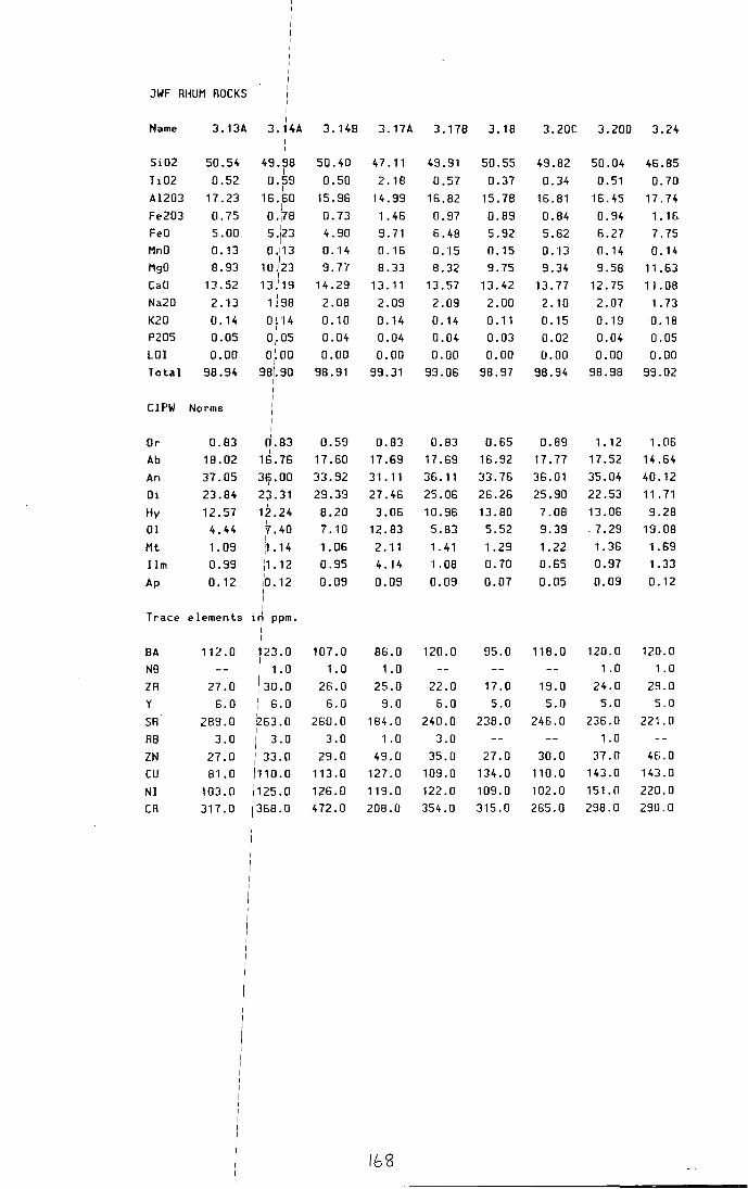
JWF RHUM ROCKS
Name 3 .13A 3. 4A 3.148 3.HA 3.178 3.18 3.20C 3.200 3.24
Si02 50.54 49.98 50.40 47.11 49.91 50.55 49.82 50.04 46.85 I
Ti02 0.52 0.59 0.50 2. 18 0.57 0.37 0.34 0.51 0.70 I
Al203 17.23 16.60 15.96 14.99 I
16.82 15.78 16.81 16.45 17.74 Fe203 0.75 0.178 0.73 1. 46 0.97 0.89 0.84 0.94 1. 1G FeD 5.00 I
5.123 4.90 9.71 6.48 5.92 5.62 6.27 7.75 MnO 0. 13 0.113 0.14 0.16 o. ·1s 0.15 0.13 0.14 0. 14
I MgO 8.93 10.123 9. 77 8.33 8.32 9.75 9.34 9.58 11 .63
I CaD 13.52 13; 19 14.29 13. 11 13.57 13.42 13.77 12.75 11.08 Na20 2.13 1 j 98 2.08 2.09 2.09 2.00 2.10 2.07 1. 73 K20 0.14 0 j "14 0.10 0.14 0.14 0.11 0. 15 0. "19 0.18
I
P205 0.05 0~. OS 0.04 0.04 0.04 0.03 0.02 0.04 0.05 LOI 0.00 o;.oo 0.00 0.00 0.00 0.00 0.00 0.00 0.00 Total 98.94 98/.90 98.91 99.31 99.06 98.97 98.94 98.98 99.02
CIPW Norms
Or 0.83 0.83 0.59 0.83 0.83 0.65 0.89 1. 12 1.06 I
Ab 18.02 16.76 17.60 17.69 17.69 16.92 17.77 17.52 14.64 I
An 37.05 39.00 33.92 31. 11 36. 11 33.76 36.01 35.04 40.12
Oi 23.84 23.31 29.39 27.46 25.06 26.26 25.90 22.53 11 . 71
Hy 12.57 1z.24 8.20 3.06 10.96 13.80 7.08 13.06 9.28 I
01 4.44 '7.40 7.10 12.83 5.83 5.52 9.39 . 7.29 19.08 I
Mt 1.09 ~. 14 1.06 2. 11 1. 41 1.29 1.22 1.36 1.69 11m 0.99 11. 12 0.95 4. 14 1.08 0.70 0.65 0.97 1. 33
I 0.09 0.09 0.09 0.07 0.05 0.09 0. 12 Ap 0. 12 10.12
I I
Trace elements . I II") ppm.
I
I 8A 112.0 123.0 107.0 86.0 120.0 95.0 118.0 120.0 120.0
i N8 I 1.0 1.0 1.0 1.0 1. 0
ZR 27.0 I 3Q.Q 26.0 25.0 22.0 17.0 19.0 24.0 29.0 y 6.0 I 6.0 6.0 9.0 6.0 5.0 5.0 5.0 5.0 I
I
SR 289.0 263.0 260.0 184.0 240.0 238.0 246.0 236.0 221.0 I
R8 3.0 I 3.0 3.0 1.0 3.0 1. 0 I
ZN 27.0 i 33.0 29.0 49.0 35.0 27.0 30.0 37.0 46.0
cu 81.0 /110.0 113.0 127.0 109.0 134.0 110.0 143.0 143.0
Nl 103.0 1125.0 126.0 119.0 122.0 109.0 102.0 151.0 220.0 I
CR 317.0 1368.0 472.0 208.0 354.0 315.0 265.0 298.0 290.0 I
lbB
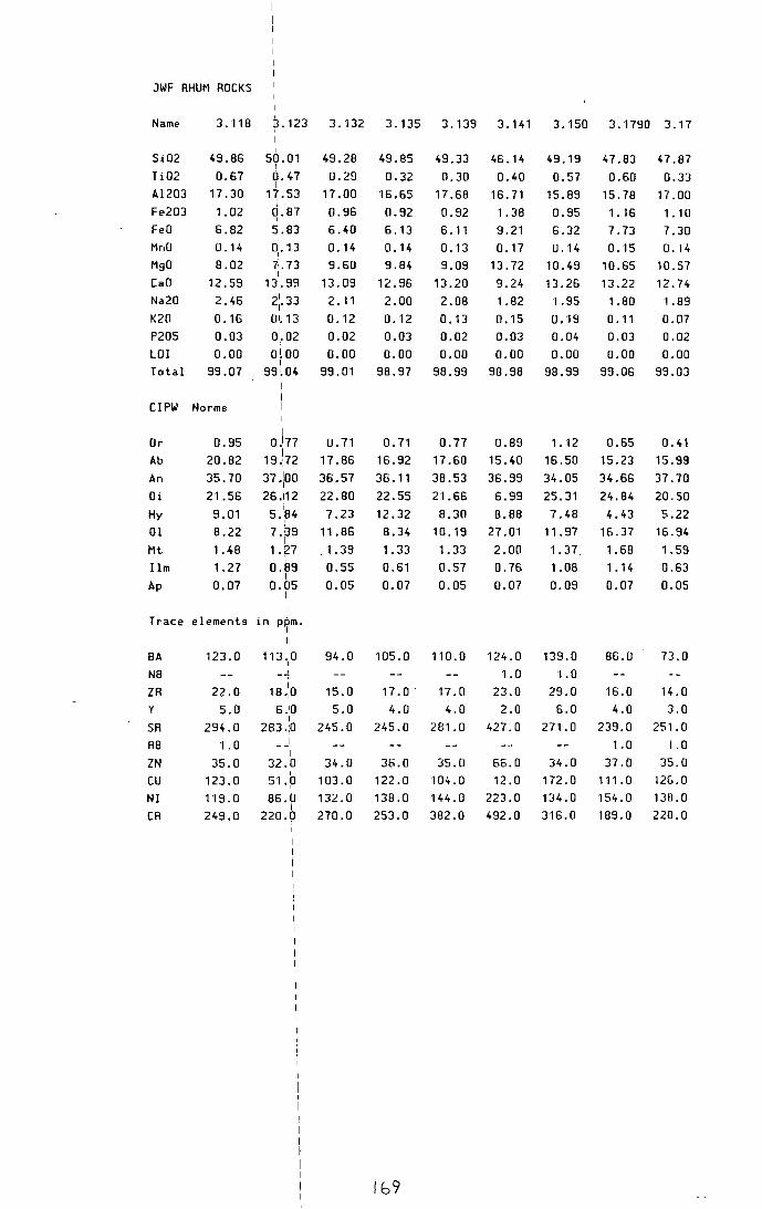
JWF RHUM ROCKS
Name 3. 118 3.123 3.132 3.135 3.139 3.141 3.150 3."1790 3.17 I
I I
Si02 49.86 58.01 49.28 49.85 I
49.33 46.14 49.19 47.83 47.87 Ti02 0.67 0.47 0.29 0.32
I 0.30 0.40 0.57 0.60 0.33
Al203 17.30 17.53 17.00 16.65 17.68 16.71 15.89 15.78 17.00 I
Fe203 1.02 0.87 0.96 0.92 I
0.92 1. 38 0.95 1.16 1. 'I 0 FeO 6.82 5.83 6.40 6.13 6. 11 9.21 6.32 7.73 7.30 MnO 0. 14
I a,. 13 0.14 0. 14 0.13 0.17 0.14 0.15 0.14 MgO 8.02 7•. 73 9.60 9.84 9.09 13.72 10.49 10.65 10.57 CaO 12.59
I 13.09 12.96 131.99 13.20 9.24 13.26 13.22 12.74
Na20 2.46 2'1.33 2. 11 2.00 2.08 1. 82 1.95 1.80 '1.89 K20 0.16 QI.'IJ 0. '12 0.12 0.13 0.15 0.19 0.11 0.07 P205 0.03 o1.o2 0.02 0.03 0.02 0.03 0.04 0.03 0.02 LOI 0.00 OlOO 0.00 0.00 0.00 0.00 0.00 0.00 0.00 Total 99.07 99lo4 99.01 98.97 98.99 98.98 98.99 99.06 99.03
I
CIPW Norms I I
Or 0.95 o.\11 U.71 0.71 0.77 0.89 1.12 0.65 0.41 Ab 20.82
I 19.172 17.86 16.92 17.60 15.40 16.50 15.23 15.99
An 35.70 37 .:oo 36.57 36. 11 38.53 36.99 34.05 34.66 37.70 Oi 21.56 26.112 22.80 22.55 21.66 6.99 25.31 24.84 20.50 Hy 9.01 5.
1
84 I
7.23 12.32 8.30 8.88 7.48 4.43 5.22 01 8.22 7.89 11.86 8.34 10. 19 27.01 11.97 16.37 16.94
I Mt 1.48 1.27 '1,39 1. 33 1. 33 2.00 1.37 1.68 '1.59 Ilm 1.27 O.S9 0.55 0.61 0.57 0.76 1.08 1.14 0.63
I Ap 0.07 0.05 0.05 0.07 0.05 0.07 0.09 0.07 0.05
I I
Trace elements I in ppm. I I
BA 123.0 113Jo 94.0 105.0 110.0 124.0 139.0 86.0 73.0 I
NB ' 1.0 1.0 ZR 22.0 I 18.10 15.0 17 .o. 17.0 23.0 29.0 16.0 14.0 y 5.0 6.10 5.0 4.0 4.0 2.0 6.0 4.0 3.0
I SR 294.0 283.:0 245.0 245.0 281.0 427.0 271.0 239.0 251.0
R8 1. 0 I 1.0 1.0 I
ZN 35.0 32.0 34.0 36.0 35.0 66.0 34.0 37.0 35.0 I cu 123.0 51.p 103.0 122.0 104.0 12.0 172.0 1'11. 0 12G.O
NI 119.0 86.0 132.0 138.0 144.0 223.0 134.0 154.0 138.0 I
CR 249.0 220.0 270.0 253.0 382.0 492.0 316.0 189.0 220.0
lb9
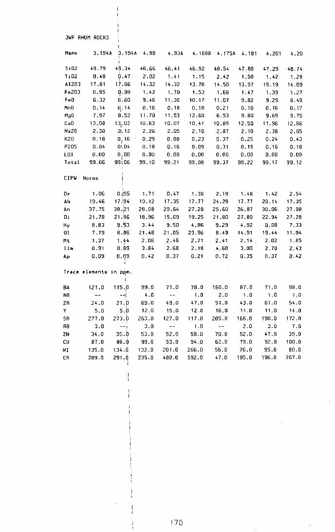
JWF RHUM ROCKS
Name 3.194A 3.194A 4.98 I
4.93A 4.1698 4.175A 4.181 4.201 4.20
Si02 Ti02 Al203 Fe203 FeD MnO MgO CaO Na20 K20 P205 LOI Total
CIPW
Or Ab An Oi Hy
01 Mt Ilm
Ap
49.79 0.48
11 .8·1
0.95 6.32 0. 14 7.97
13.08 2.30 0. 18 0.04 0.00
99.06
Norms
1.06 19.46 37.75 21.78 8.83 7.79 1.37 0.91 0.09
Trace elements
BA 12·1. 0 N8
ZR 24.0 y 5.0
SR 277.0 RB 3.0
49.34 I Q.47
17.66 I
q.99 6.60 I
0,. 14 8.52
I 131.02
21. 12 0
1• ·15 I
0 1.04 0~00
I 99~06
I I
I I I
0.195
~;::~~ 21 ·\16 9.53 8.86
I 1. 44
I
0.89 I
0.09 I
I
. I 1n P8m.
I I
115 "Ia --1
21.p 5.0
I 273.0
I
--I
46.66 2.02
14.32 1.42 9.46 0. ·16
11.70 10.63 2.26 0.29 0. 18 0.00
99.10
I. 71 19.12 28.08 18.96 3.44
21.48 2.06 3.84 0.42
99.0 4.0
69.0 .12 .0
263.0 3.0
46.41 1. 4.1
14.32 1. 70
11 .30 0. 18
11.53 10.07
2.05 0.08 0.16 0.00
99.21
0.47 17.35 29.64 15.69 9.50
21.05 2.46 2.68 0.37
71.0
49.0 15.0
127.0
46.92 1.15
13.70 1. 53
10.17 0. ·18
12.60 10.41 2.10 0.23 0.09 0.00
99.08
1. 36 n.11
27.28 19.25 4.86
23.96 2.21 2.18 0.21
78.0 1. 0
47.0 12.0
117.0 1.0
ZN
cu NI CR
34.0 35.0 53.0 52.0 58.0 I
87.0 86.0 99.0 53.0 94.0 135.0 134.0 132.0 201.0 266.0
I 289.0 291.Q 235.0 480.0 592.0
170
48.54 2.42
14.50 1.66
11.07 0.21 6.53
10.89 2.87 0.37 0.31 0.00
99.37
2.19 24.29 25.60 21.80 9.29 8.49 2.41 4.60 0.72
160.0 2.0
5·1.0 16.0
205.0
47.80 1.58
13.57 1. 47 9.82 0. 18 9.80
12.50 2. •JD
0.25 0. 15 0.00
99.22
1.48
17.77 26.87 27.80 4.92
14.91 2.14
3.00 0.35
87.0 1.0
43.0 11.0
166.0 2.0
47.29 1. 42
15. 19 1. 39 9.29 0.16 9.69
11.96 2.38 0.24 0.16 0.00
99. 17
1. 42 20.14 30.06 22.94 0.08
19.44 2.02 2.70 0.37
71.0 1.0
5·1.0
11.0
190.0 3.0
48.74 1.28
14.09 1.27 8.49 0.17 9.75
12.66 2.05 0.43 0.18 0.00
99. 12
2.54 17.35 27.98 27.28 7.33
11.94 ·1.85
2.43 0.42
98.0 1.0
54.0 14.0
172.0 7.0
70.0 52.0 47.0 39.0 62.0 79.0 92.0 100.0 56.0 76.0 95.0 80.0 47.0 195.0 196.0 207.0

JWF RHUM ROCKS I I I
Name 5.53A : 5. 78 5. 10 5. 11 5. 15 5.25 5.32A 5.328 5.36
I I
Si02 45.99 51.78 I
50.65 59.17 51.01 47.47 54.41 53.63 63.40 Ti02 0.82 1 o.9·1 1. 31 1. 80 1.23 2.20 2 .2"1 1 . "11 0.81 Al203 1"1. 63 i14.62 14.44 13.81 14.84 14.89 13:13 "14.28 15. "12
'Fe203 1. 40 \0.86 1. 36 1.09 1.05 1.55 1.50 1.08 0.69 FeD 9.35 15.76 9. 10 7.29 7.02 10.34 10.02 7.17 4.60 MnO 0.17 :a.13 0.17 0. 14 0.14 0.18 0.17 0.14 0. 11 MgO 19.83 18.98 8.14 3.45 8.90 8.25 5.08 7.84 2.98
I 1 f. 79 CaD 7.64 112.27 10.88 6.28 11.55 7.69 9.98 4.02
Na20 1.65 \2.47 2.48 3.57 2.35 2.40 3.26 2.66 3.22 K20 0.16 11.04 0.49 2.09 0.71 0. 14 1.34 0.94 3.49 P205 0.09
I
,a. 10 0. 12 0.29 0.18 0.10 0.37 0.14 0.25 LOI 0.00 0.00 0.00 0.00 0.00 0.00 0.00 0.00 0.00
I Total 98.73 9~.93 99.14 98.98 98.98 99.31 99.19 98.96 98.69
CIPW Norms ! I I
Ctz I __ I
11.15 5.01 2.27 16.28 Or 0.95 6. 15 2.90 12.35 4.20 0.83 7.92 5.56 20.63
I Ab 13.96 20.90 20.99 30.21 19.89 20.31 27.59 22.51 27.25
I An 23.86 25.74 26.83 15.49 27.85 29.45 17.24 24.26 16.50
Di "10. 76 I
271.72 21.54 11 . 44 22.84 23.22 15.34 19.76 1.49 Hy 10.36 81.92 18.59 12.66 16. 15 6.03 18.86 20.63 13.44
I 01 35.05 6'.29 3.56 3.78 12.83 Mt 2.03 11.25 1.98 1.58 1. 53 2.25 2.18 1.56 1. 00
I Ilm 1.56 n73 2.49 3.42 2.34 4.18 4.20 2. 11 1. 54 Ap 0.21 o\23 0.28 0.67 0.42 0.23 0.86 0.32 0.58
Trac:e elements in ppm. I I
BA 107.0 16l0 165.0 588.0 221.0 104.0 367.0 268.0 1246.0
N8 2.0 2.0 8.0 2.0 5.0 2.0 10.0
ZR 50.0 1d.o 67.0 183.0 73.0 30.0 154.0 115.0 202.0 y 9.0 141.0 13.0 29.0 15.0 11.0 27.0 18.0 28.0
SA 93.0 1941.0 168.0 228.0 209.0 180.0 181.0 174.0 4C5.0
RB 2.0 2oi.o 9.0 47.0 14.0 19.0 16.0 8"1.0
ZN 54.0 34lo 57.0 69.0 44.0 68.0 71.0 55.0 72.0
cu 79.0 42lo "107. 0 33.0 98.0 90.0 46.0 90.0 30.0 I
NI 636.0 92 !0 73.0 35.0 113.0 80.0 33.0 76.0 JG.O
CA 960.0 2s9!o 242.0 60.0 380.0 194.0 30.0 216.0 79.0
1/l

JWF RHUM ROCKS
Si02 Ti02 Al203 Fe203 FeD MnO MgO CaD Na20 K20 P205 LOI
5.39
52.02 1. 25
15.36 1.26 8.41 0.16 6.13
10.87 2.58 1.00 0. 11
0.00
15.41
I ~1. 73
i 1.11 14.78 lo.85 I 15.63
r14 . 7. 31 I
13.97 l2. 11
lo.6o 10.17 :o.oo
5.428
53.53 1. 37
15.18 1.06 7.06 0. "13
6.28 10.09
3.01 I. 15 0. 15 0.00
5.42C
53.92 2.34
12.92 1. 48 9.84 0.16 6.03 8.04 2. 77
1.49 0.19 0.00
5.45
50.46 1.05
'14. 41 1. 11
7.40 0.15 9.22
12.27 2,3'1 0.50 0.15 0.00
5.46A1 5.46A2 5.46C
50.36 50.97 48.96 1.07 1.04 2.94
14.42 14.68 13.18 1.02 0.98 1.66 6.83 6.52 11.04 0.15 0.14 0.17 9.91 9.46 7.39
12.51 12.37 9.89 2.02 2.19 2.93 0.55 0.49 0.77 0.13 0.13 0.38 0.00 0.00 0.00
5.80
52.83 1. 63
12.41 1. 48 9.87 0.20 7.28
10.02 2.27 1.08 0.10 0.00
Total 99.15 9,9.00 99.01 99 .. 18 99.04 98.98 98.97 99.31 99.17
CIPW Norms
Cltz
Or Ab An Oi Hy
01 Mt I lm Ap
0.89 5.91
21.83 27.38 21.23 17.45
1.83 2.37 0.25
i I--3.55 I
22.93 I
26.40 I
33.73 I 5.19 I 3.48 1.23 2.11
0.39
Trace elements in lppm.
BA N8 ZR y
SR R8
ZN
cu NI CR
340.0 2.0
60.0 12.0
218.0 15.0 49.0 59.0 45.0
181.0
1Jro 12.0
615.0 1i4. 0
205.0 1
1
1 . 0 I
36.0 I
146.0 70.0
14S.O
I I I
1. 78 6.80
25.47 24.52 20.03 15.94
1.54 2.60 0.35
315.0 2.0
105.0 17.0
232.0 20.0 48.0 63.0 45.0
'122.0
4.74 8.81
23.44 18.43 16.66 20.08
2.14
4.44 0.44
374.0 3.0
117.0 20.0
165.0 23.0 59.0 53.0 47.0 56.0
172
2.95 3.25 19.55 17.09 27.48 28.66 26.23 26.22 12.01 13.90 6.87 6.04 1.61 1.49 1. 99 2. 03 0.35 0.30
191.0 2.0
45.0 13.0
197.0 5.0
44.0 65.0 60.0
266.0
2'17. 0
2.0 93.0 14.0
194.0 10.0 58.0
111.0 84.0
423.0
2.90 18.53 28.79 25.56 15.73 3. 7i 1. 42 1. 98 0.30
208.0 2.0
54.0 13.0
206.0 9.0
55.0 115.0 82.0
456.0
4.55 24.79 20.54 21.37 10.76 8.43 2.40 5.58 0.88
198.0 5.0
66.0 25.0
169.0 9.0
78.0 77 .o 64.0 95.0
2.98 6.38
19.21 20.49 23.47 21.18
2.15 3.10 0.23
238.0 2.0
62.0 13.0
15G.O 22.0 57.0 73.0 38.0 59.0

JWF RHUM ROCKS
Name
Si02
Ti02
Al203
Fe203
FeD
MnO MgO CaO Na20 K20 P205
LOI Total
5.8oc I 5.1658 5.169A 6.48
I
6.78
51.13
1.57
11.37
2.00
13.31
152.15 45.40 69.80 51.87
0.90
14.70
0.86
5.75
0.87 0.76 0.86
19. 17 11 . 14 12 . 40
0.65 1.45 0.59
4.36 9.63 3.90
0.18 0.10
7.31 3.91
9.32 14.20
2.37 2.92
0.78 0.62
0.06 0.11
0.00 0.00
99.40 I 99.06
0. 17
21.20
7.54
0.99
0.32
0.09
0.00
98.69
0.09 o. "13
0.80 8.88
2.44 12.24
3.76 2.43
3.72 1.02
0.23 0.11
0.00 0.00
98.59 98.90
CIPW Norms
Qtz Or Ab An Ne Oi
Hy
01
Mt Ilm Ap
Trace
BA NB ZR y
SA
RB ZN
cu NI CR
0.30
4.61
20.06
18.09
23.06
27.27
1. 00 3.66
24.71
37.38
26.38
3.08
2.89 i 0. 95
2.98 : 1.65 0.14 I 0.25
I I
element~ in ppm. I I
142. 0 I 171 . 0 I
1.0 i 1.0
33.0: 59.0
9.0 i 10.0 104.01 262.0
13.0 I 12.0
48.o I 24.o
33.0: 90.0 37.01 43.0
I 74.01 113.0
1.89
8.38
25.01
9.43
15.71
34.52
26.44
21.98
31.82
5.98
3.95
5.40
2.10 0.85
1. 44 1 .63
0.21 0.53
115.0 1184.0
1. 0
38.0
9.0
8Ei. 0
6.0
57.0
39.0
655.0
815.0
14.0
240.0
39.0
223.0
96.0
82.0
27.0
27.0
2.0
173
6.03
20.56
26.20
27.19
10.69
5.02
1.25
1. 71
0.25
165.0
2.0 113.0
14.0
197.0
25.0
33.0
44.0
88.0
256.0
6.163P 6.163V 6.1798 6.16
50.19
1.54
11 .28
I. 16
7.75
54.45
2.45
12.13
0.99
6.58
0.15 0.13
13.32 4.94
9. 62 1'1. 51
3.38 5.21
0.14 0.19
0.30 0.48
0.00 0.00
98.83 99.06
73.27
0.43
11 .80
0.21
1.40
49.47
0.34
16.68
0.85
5.64
0.05 0.13
'1. 40 10. 17
0.71 13.48
2. 75 2 .OJ
6.20 0.12
0.08 0.02
0.00 0.00
98.30 98.93
0.83
28.60
15.20
29.67
1.12 36.64
43.14 23.27
9. 16 . 1. 55
0.52
0.71
'17.18
36.05
24.49
3.89
20.52
1.68
2.92
0.70
316.0
8.0
162.0
28.0
153.0
5.0
42.0
89.0
423.0
531.0
36.48 1.17
1.45
1. 43
4.65
1. 11
194.0
4.0
99.0
19.0
130.0
2.0 40.0
102.0
93.0
76.0
4.69
0.30
0.82
0.19
498.0
11.0
161.0
49.0
69.0
212.0
23.0
39.0
52.0 23.0
24.65
7.07
11.35
1.23
0.65
0.05
93.0
19.0
4.0
259.0
3.0 27.0
43.0
95.0
264.0

JWF AHUH ROCKS
Name 6.20A
Si02 43.08 Ti02 0.21
Al203 15.09 Fe203 1.66 FeO 11.06 HnO a. ·t8
MgO 18.96 CaO 7.37
Na20 1.23 K20 0.03 P205 0.03 LOI 0.00 Total 98.90
CIPW Norms
Or 0. 18 Ab 10.41
An 35.57 Oi 0.64 Hy 6.27 01 42.97
Mt 2.41 Ilm 0.40
Ap 0.07
Trace elements in ppm. I I
BA 38.0 I
NB ZA 7.0 y
SR 144.0 AB ZN 58.0 cu 8.0 NI 564.0 CA 1436.0
174-
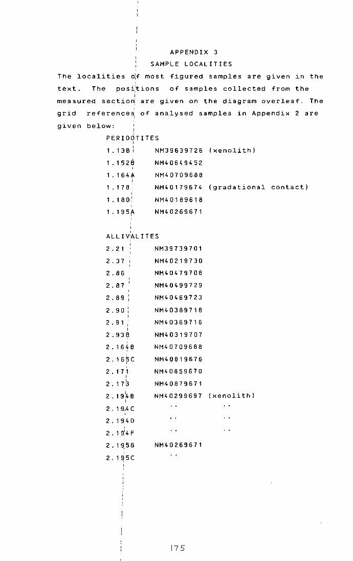
APPENDIX 3
SAMPLE LOCALITIES
The localities ~f most figured samples are given in the I
text. The pos~tions of samples collected from the I
measured sectiori are given on the diagram overleaf. The I I
grid reference~ of analysed samples in Appendix 2 are I
given below:
PERIDOTITES I I
1 . 1 3 8 ! NM39639726
1.1s28 NM40649452 I
1.1s4A NM40709688 j
1 . 17 8: NM40179674 I
1 . 1 8 0: NM40189618
1.195f\. NM40269671 I
I
ALL IV 1AL I TES
2 . 2 1
2.37
2.86
2.87
2.89
2.90
2 . 9 1
2.938 I
I
2.1648 I
I
2.165C I I
2.1 H I
2. 1 7 3 I
NM39739701
NM40219730
NM40479708
NM40499729
NM40469723
NM40389718
NM40369716
NM40319707
NM40709688
NM40819676
NM40859670
NM40879671
(xenolith)
(gradational
2.191
48 I
NM40299697 (xenolith)
2 . 1 9:4 c I
2. 1 9:4 0 I
2.19:4F I
2.19:58 NM40269671 I
2.1~5C
175
contact)

"SHEETROCKS"
3 . 1 2 NM39679728
3. 13A NM39639726
3. 1 4 A NM39589721
3. 1 4 8
3. 1 7 A NM39699718
3.18 NM39749716
3.20C NM39799715
3.200
3.24 NM39829720
3 . 1 1 8 NM40209712
3. 1 2 3 NM40209711
3. 1 3 2 I NM40189710 I
I 3. 1 3 5 I NM40179710 I
3. 139: NM40169710 I
3 . 1 4 1 i NM40159710
3. 1 5o: NM40139709
3 . 1 7 9/o NM40449661 I I
3. 1 9 41A NM40299697
I
GABBRO PLUGS, SHEETS, DYKES I
4.98: NM39479753 I
(dyke) 4.93~ NM40319707 I
4.16~8 NM40989638 (dyke) I
4.175A NM40909672 (sill) I I
4 . 1 8 '1 I
NM40109613
4. 2 0 ;1 NM40489533 I
4. 20:2 NM40169499
l7G

I I
MAR G I NIA L S U I T E
5.53A
5.78
5. 1 0
5 . 1 1
5. 1 5
5.25 j
5. 3 2A : I
5. 3 28 i
5.36
5.39
5 • 4 1
5.428
5.42C
5.45
5.46A C
5.80A
5. 8ocl I
5.165;8
5.169/A i I I
VARIa/us
6.48
6. 7 8 : I
6.163P i
6. 1 6 jV I I
6.17~8 I
6. 1 6~
6.204 I
NM38609549
NM39189753
NM39409747
NM39379746
NM39239750
NM39189753
NM40339746
NM40299739
NM40019742
NM40429731
NM40389735
NM395940
NM40679722
NM40829676
NM40989638 (xenolith)
summit of 8einn nan Stac
NM40649731
NM40719696 (mostly peridotite)
(vein cutting 163P)
NM40449661 (acid sheet)
NM39659720 (beerbachite xen.)
NM39799715
177
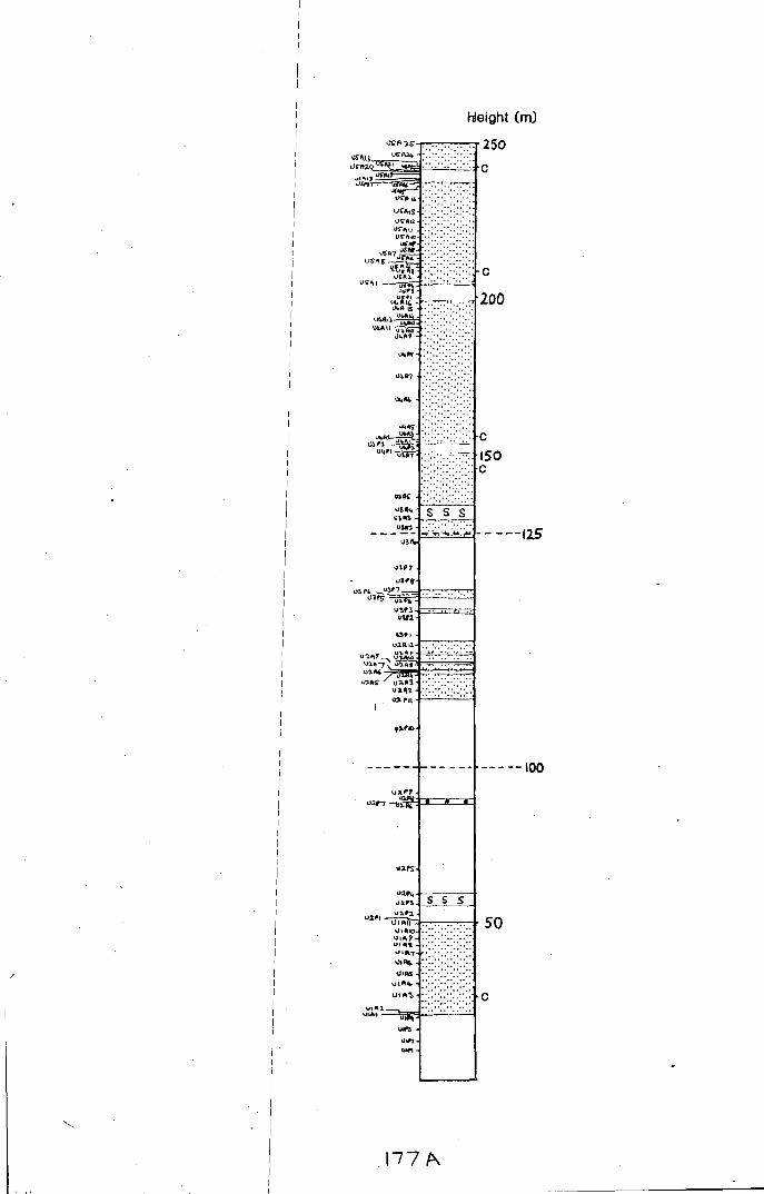
/
hleight (m)
........ . .. .. .. .
. .. .. .. . IJ4A1 .••.••••
-- --- --- --100
u2~• +-5--c
5c-
5-=--t
"'" ,__~---, \.1
2'' ~3----=-~ 50
VI IIIlO \Jill\?
"''" \Jif'7 ••••••••
'"" ........ U\Ait-
U'~~
""" UIO> -
177 p...,

I G,u[. Mag. 122 (5) 1985, pp. 459--468. Printed in Gre~t Britain 459
I
The Lower Eastern Layered Series of Rhum I
I JOHN W. FAITHFULL"'
I Department of Geological Science~. University of Durham, South Road, Durham, DHI 3LE, U.K.
I I
I (Receivep 2 November 1984; accepted 3 April 1985)
I Abstract- The Lower Eastern Layered Series (LELS) comprises approximately units 1-5 of previous workers. Remapping has revealed I considerable along-strike lithological variation in the units of the LELS. It is suggested, on the basis ~ffield and geochemical evidence, that two layers formerly regarded. as' conformable intrusive sheets of fine-grained olivine gabbro', may be evolved allivalite layers rather than later intrusions. Xenolith suit1~s. in these layers and elsewhere, indicate a component derived from the roof or walls of the magma .:;hamber. Cryptic variation is more extensive in the LELS than in other parts of Rhum: olivine 1forsterite content varies from 85.6 to 70, and clinopyroxene MgXIOO/(Mg+ Fe) varies from 88 to 74. Postcumulus effects and subsolidus re-equilibration have altered the initial compositions oft he mineral phases. The data are consistent with a model of repeated replenishment by picritic magma, although the replenishing liquids may have been slightly less magnesian than those subsequentty available, during the formation of the upper ELS.
I
I. Introduction
I I I I
The Eastern Layered Series (ELS) of R~um (Brown, I
1956) are well known for the spectacular 1development
of large-scale cyclic layering. Brown ( 1956) divided the sequence into 15 units, each comprising a peridotite layer overlain by an allivalite layer. H
1e interpreted
these units as the products of crystallizarion of pulses of olivine basalt magma. Using the techniques of the time, he could detect no cryptic variation in any of the units, and thus argued that they could 6nly represent a small degree of crystallization at a relat
1
ivcly constant high temperature. He noted that the lower units were orthocumulates, in contrast to. the ad-: and heteradcumulates of the upper ELS. Brown 1 mapped two layers of 'fine-grained olivine gabbro', conformably intruding the layered rocks, obscuring ;much of units 4 and 5. Following Bailey (1945) he argued that the layered rocks occurred within a ring fault and that they had been emplaced upwards as a semi1-solid cylinder along the fault, lubricated by basaltic m~gma now seen as a gabbroic ring dyke at the margins 0f the complex.
The present work is mainly concerned with units 1-5, hereafter referred to as the tower Eastern Layered Series (LELS). /
2. Field relations I
I Remapping (Fig. I) has substantially revised Brown's map of the area, revealing in particular considerable lateral changes in lithology within ~he LELS. The 'intrusive conformable sheets of fine~grained olivine gabbro' have been included in units 4 ::ind 5 of the ELS. The reasott8 for this are discussed lat~r.
I
I
• Present address: Department of Geo(ogy. University of Leicester. LEI 7RH, U.K.
2.a. Marginal relationships
Much of the eastern margin of the ultra basic complex is a near-vertical ring fault, largely occupied by a heterogeneous gabbroic--dioritic ring dyke known as the marginal gabbro. The contact with the layered rocks is rarely seen, and the few exposures are difficult to interpret due to intense weathering, but over most of the area there is little obvious deformation of the layered rocks near the fault. However,just north of the Alit nam Ba, the allivalites of unit I increase sharply in dip towards the marginal gabbro (up to 30-40° to the west) although the contact is not exposed. The Torridonian sediments in this area dip very steeply to the west, in contrast to the regional dip of I Q-20° to the northwest. This situation is more consistent with subsidence rather than uplift within the ring fracture.
2.b. The layered rocks
The LELS comprises some 250 m of olivineand olivine-plagioclase-(clinopyroxene) cumulates. Whereas the upper ELS rocks are mainly adcumulate and heteradcumulate peridotites and troctolites, those in the LELS are orthocumulates, often rich in clinopyroxene. Peridotite forms the bulk of the upper ELS sequence; in the LELS about 60% of the thickness is allivalite. Chrome-spinel seams and harrisite layers are often associated with the upper ELS peridotites, but chromite seams are rare, and harrisites unknown in the LELS.
Lateral lithological variation is a: marked feature of the LELS (Fig. 1 ). This makes the subdivision into five units, as defined in the Alit nam Ba, rather difficult to extend into the northern part of the area.
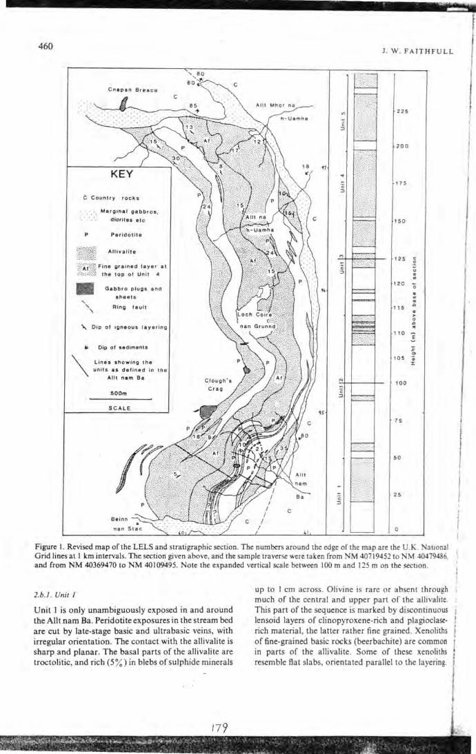
' - ... 1'"':' . - -460
C Count r y rocks
Marginal gabbros , diorites etc
P Peridot i te
T}{:ffi\\\\ Allivalite
l"{=;~:~:~i~~~. F;~: ~~:i:~d u':i:er• at
• Gabbro plugs and
sheets
' ' ' Ring fault
"' Dip of igneous layering
...
\ Dip of sediments
Lines showing the
units as defined in the
Alit nam Be
SO Om
SCALE
"'
c ::J
c
J. W . FAITHFULL
225
200
17 5
150
125 c 0
u
" .. 120 0 .. .. .. 115 D ..
> 0
D .. 110
E
.c "' 105 .. :I:
100
75
50
25
Figure I. Revised map ofth.e LELS and stratigraphic section. The numbers around the edge of the map are the U.K. ational Grid lines at I km intervals. The section given above, and the sample traverse were taken from NM 40719452 to M 40479486, and from NM 40369470 to NM 40109495. Note the expanded vertical scale between 100m and 125m on the section.
2.b.l. Unit I
Unit I is only unambiguously exposed in and around the Alit nam Ba. Peridotite exposures in the stream bed are cut by late-stage basic and ultrabasic veins, with irregular orientation. The contact with the allivalite is sharp and planar. The basal parts of the allivalite are troctolitic, and rich (5%) in blebs of sulphide minerals
up to I em across. Olivine is rare or absent through much of the central and upper part of the allivalite. This part of the sequence is marked by discontinuous lensoid layers of clinopyroxene-rich and plagioclaserich material, the latter rather fine grained. Xenoliths of fine-grained basic rocks {beerbachi te) are common in parts of the allivalite . Some of these xenoliths resemble flat slabs, orientated parallel to the layering.
I I I
! 1

Lower Eastern Layered Series
2.b.2. Unit 2 i i I
Unit 2 is only well exposed around the Alit nam Ba. The unit is a complex one containing maAy subsidiary peridotites and allivalites. The unit is 1 about 65 m thick, most of this being peridotite. Thelcontact with unit I is planar, sharp, with no chrome1~spinel seam. A few metres above the base the peridotite contains a slumped and contorted layer of allivalit~, which thins and disappears to the north. Such deforrned layers are
I
common in units 2 and 3. They aremarke9 by low-angle folding and the development of load !Structures of peridotite into allivalite. Despite the in
1
tensity of the small-scale deformation these disturbbd layers are concordant with the enclosing rocks. P..nother such laver occurs about 15 m below the main allivalite.
-The main allivalite is a clinopyroxene-~oor troctolite resembling the classic allivalites of the upper ELS. This allivalite contains three small peridotite layers. Each of these has an undulating upper surface w
1ith • fingers' of
peridotite extending up into the overlyi~g rock. These 'fingers' cut sharply across recumbent 1slump folds in the overlying allivalite with no visible deformation. These are considered in detail elsewhere (Butcher, Young & Faithfull, this issue).
1
2.b.3. Unir 3
Unit 3 is the most extensive in the LELS, exhibiting considerable lateral changes in 1i tho logy. The boundary with unit 4 is only clear-cut in the sou~h; to the north the allivalite of unit 3 merges with that of unit 4. due to the northward thinning of unit 4 peridotite. In the Alit nam Ba section, unit 3 co~tains se1~eral subsidiary allivalites and peridotites, and the main allivalite is troctolitic in the basal parts. Elsewhere, the main allivalite is largely an unlaminated clihopyroxene-rich type, with troctolite confined to thiri discontinuous layers. These clinopyroxene-rich rocks~closely resemble gabbros, and parts of the sequence have in the past been mapped as such, despite thei lack of visible contacts and the presence of layering. Xenoliths are fairly common in the clinopyro~ene-rich facies. Beerbachite, troctolite, peridotite an:d gabbro are all represented. 1
Below the main unit 3 allivalite. east of Loch Coire nan Grunnd. peridotite overlies a thih troctolite layer, not traceable away from this locality. This contact is notable for the development of thr.ee chrome-spinel seams. the only ones seen in the LELS.
I I I
2.b.4. Unir 4 1
The peridotite taken as the base oflunit 4 in the Alit nam Ba is only 2-3m thick and has a rather weathered and altered appearance. It cannot b,e traced far to the north. In the Alit nam Ba the basal part of unit 4 allivalite is a well-layered, rather wekthered troctolite;
I I
30 I I
461
this passes up into unlayered clinopyroxene and Fe-Ti oxide-rich material with abundant xenoliths of beerbachite and ultra basic rocks. To the north of the Alit nam Bathe troctolitic facies is not well developed,· and the orthocumulates of unit 3 pass up into those of unit 4 with no clear boundary. This thick allivalite is referred to as unit 3/4 allivalite. The xenoliths becomes increasingly abundant with height in unit 4 until suddenly there is a decrease in grain size, over about 2m. This finer grained layer was mapped by Brown (1956) as an ·intrusive sheet of fine-grained olivine gabbro'. However, the lack of obviously· intrusive contacts, and the presence of layering structures and xenoliths in both the fine-grained layer and the underlying allivalite suggest that it may be part of the layered series.
A wide variety of xenoliths occurs in these rocks. Beerbachite blocks, up to I 0 m long, with clots and veins of calc-silicate minerals, finely lamin.ated anorthosites and troctolites, peridotite and gabbro are all represented. These display a number of mineralogical curiosities. Ferri-fassaite, green in the field, bright yellow in thin section, is common in the calc-silicate rocks, together with grossular, plagioclase, and other minerals. This intimate association of calc-silicates with beerbachite. strongly suggests that these xenoliths may represent thermally metamorphosed amygdaloidal basalts. One of the fine-grained anorthosite xenoliths (rather similar to the fine-grained plagioclase layers in unit I) contains a layer rich in poikilitic crystals of inverted pigeonite- indicating that feldspar cumulates more fractionated than any we now see were forming in the Rhum magma chamber.
2.b.5. Unil 5
Unit 5 peridotite is not well exposed but, where exposed, the contact with the overlying allivalite is gradational, over a distance of about I m. Such gradational peridotite-allivalite contacts are unusual in the LELS; normally such contacts are sharp and abrupt. In this instance the contact is marked by a zone of fine scale (1-5 em) olivine-rich and plagioclase-rich
.layers, the olivine-rich layers becoming thinner and less clearly marked upwards.
The allivalite of unit 5 corresponds to the upper ·intrusive sheet of fine-grained olivine gabbro' of Brown (1956). As with the lower sheet, it is difficult to disprove an intrusive origin, although the gradational lower contact, lack of net veining, and the presence of good internal layering suggest similiarities with the LELS allivalites rather than the clearly intrusiv~ gabbros.
Unit 5 allivalite is not so rich in xenoliths as the fine-grained facies of unit 4, although beerbachite and gabbro xenoliths are locally common. The allivalite is well layered, and in places concentrations of Fe-Ti oxides occur (Fig. 2). The upper part of this allivalite
GEO 122

462
Figure 2. Layering in unit 5 allivalite. prominent Fe-Ti oxide-rich layer occurs at the level marked X-X.
I
I
develops, in places, a rather pale, well-layered facies, which Brown (1956) interpreted 1as relics of the
. I
allivalite which had been intruded by1the sheet; explicit
evidence for this is, however, lacking.
1.c. Gabbro plugs and sheets
I
I
I Previous maps of the LELS have shown differing
' numbers of small gabbro intrusions in a variety of places. Much of this confusion has hemmed from the
I
rather 'gabbroic' appearance of ,the LELS rocks, together with the extent of hiteral lithological variation, which was not previous!~ recognized. Most of these have been reinterpreted as <;:linopyroxene-rich allivalite. However, several small plugs and inclined sheets of gabbro have been mapped on the basis of transgressive or chilled margins an
1
d lack of layering. Two of .these are intruded across the upper contact of unit 5 allivalite, cutting both it and the overlying peridotite. 1
Around the unit 3-unit 4boundaty in the area below I
Clough's Crag, thin gabbroic veins,are common. This, together with the rather altered appearance of cumulates in th.e area, may indicate the proximity of
I a gabbro intrusion, perhaps below
1the present erosion
level. This disruption occurs near the base of the xenolithic layer in unit 4 allivalite and may have been used by Brown (1956) as eviden~e for the intrusive origin of this layer. Away from thi~ area no such effects are seen, however, and it is suggested that there is no connection between the two. :
I 3. Petrography 1
I Accounts of the petrography of t~e LELS are given in Harker ( 1908) and in Brown (1956). An outline of new observations is given below. I
I
3.a. Peridotite petrography
Olivines are usually granular~rounded in shape; however, in places, particularly tt:Je peridotites in units
I
J. W. FAITHFULL
4 and 5, elongate crystals occur. These invariably display lamination. In the small peridotite layer within unit 5 allivalite, the elongate olivines appear to show two intersecting laminations (Fig. 3a). While this may be a depositional feature related to cross-lamination, it may also he caused by rotational shear during compaction of the crystal mush, or during growth in situ. In several specimens there is a suggestion that chrome-spinel crystals are concentrated along the upper surfaces of olivine crystals (Fig. 3 b). Such structures have been described by J. A. Volker (unpubl. Ph.D. thesis, Univ. Edinburgh, 1983) from Trallval on Rhum, where he considered them evidence for sinking of chrome-spinel" crystals in the interstitial liquid.
Sulphide minerals are common in trace quantities ( < 0.1% ), but in unit I peridotite they are locally abundant (1-5% of the rock), forming poikilitic blebs up to 7 mm across. Primary phases are pentlandite, pyrrhotite, chalcopyrite and cubanite. A little native copper occurs associated with alteration.
3.b. Allivalite petrography
Allivalites are characterized by the presence of cumulus plagioclase, which may or may not show lamination. Where the crystals are poikilitically enclosed in clinopyroxene, they are never laminated, even if those outside are (Fig. 3c); and the crystals inside are usually smaller than the crystals outside, unlike in olivines in peridotite (Fig. 3d). This implies that lamination, at least in allivalites, is not a depositional feature, but is developed at a late stage, probably due to compaction or shear of the crystal mush.
Very fine-grained plagioclase-rich rocks occur as layers and laminae in places. In these. the plagioclase crystals form interlocking grains, and sometimes develop triple-junction grain boundaries. They are well layered and laminated on a small scale, with variations in the size of the plagioclase and in the abundance of mafic minerals defining the layering. These rocks are common in units I (Fig. 3e) and 3, and as xenoliths in unit 4 allivalite, where they occasionally contain poikilitic crystals of inverted pigeonite (Fig. 31).
Olivine crystals arc usually inclusion-free. and lack the rounded-granular habit typical of olivine in peridotite. Habit does not seem to be rigorously controlled by position within a unit. although poikilitic olivine is rare in the basal parts of allivalites. Elongate or skeletal olivines are lacking in allivalitcs. In the slumped layers peridotite and allivalite are partly mixed; two populations of cumulus grains can be seen in thin section: the cumulus plagioclases and rather irregular cumulus olivines of the allivalite, and the rounded olivincs and chrome-spinels of the peridotite.

Loll'er Eastern Layered Series
Figure 3a. Intersecting laminations in peridotite from unit 5. Olivines parallel to the bottom of the photograph are in extinction. Scale bar = 0.5 mm.
Figure 3b. Chrome-spinel concentrations on the upper surfaces of olivine crystals from unit 2 peridotite. Scale bar= 0.5 mm.
Figure 3c. Laminated plagioclase crystals in allivalite from unit 5. Note that crystals enclosed in the clinopyroxene do not show lamination. Scale bar= 0.5 mm.
Pale green clinopyroxene is found in most rocks, sometimes showing marginal zoning. Exolution is not common but, particularly in units 3, 4 and 5. lamellae of opaque phases or orthopyroxene are occasionally seen . Orthopyroxene. although fairly common as an interstitial mineral, has only been seen as cumulus crystals in a xenolith from the upper part of unit 4.
! 81
463
Figure 3d. Laminated olivine crystals in peridotite from unit 5. Note that lamination is not affected by enclosure in clinopyroxene. Scale bar = 0.5 mm.
Figure 3e. Boundary between a fine-grained and a coarse-grained Ia yer in unit I allivalite. Note the development of triple junctions in the fine-grained layer. Scale bar= 0.5 mm.
Figure 3f. Inverted pigeonite in fine-grained plagioclase-rich cumulate. Xenolith in unit 4 allivalite. Scale bar = 0.1 mm.
Fe-Ti oxides are the dominant opaque phase in the LELS allivalites, even in the troctolitic types of units 2 and 3. They occur mostly as interstitial blebs, although in unit I allivalite large cumulus ilmenites occur near the base.
Sulphides are normally absent from allivalites, with two exceptions. The basal part of unit I allivalite
30-2
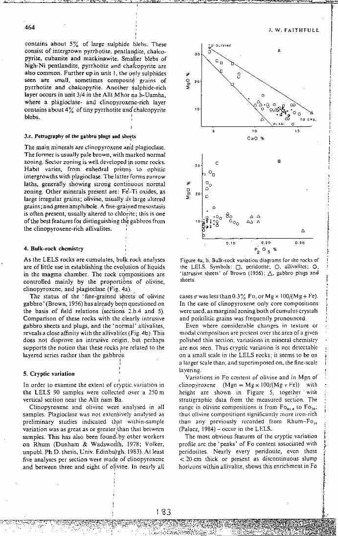
•.
464
contains about 5% of large sulphide l:) ebs. These consist of intergrown pyrrhotite, pentlan~ite, chalcopyrite, cubanite and mackinawite. Smaller blebs of high-Ni pentlandite, pyrrhotite and chal'copyrite are also common. Further up in unit I, the orily sulphides seen are small, sometimes composite grains of pyrrhotite and chalcopyrite. Another ~ulphide-rich layer occurs in unit 3/4 in the Alit Mhor ~a h-Uamha, where a plagioclase- and clinopyroxe~e-rich layer contains about 4% of tiny pyrrhotite and chalcopyrite blebs. I
I
3.c. Petrography of the gabbro plugs and sherts
The main minerals are clinopyroxene and plagioclase. The former is usually pale brown, with rnarked normal zoning. Sector zoning is well developed i;n some rocks. Habit varies, from euhedral prisms to ophitic
I intergrowths with plagioclase. The latter forms narrow laths, generally showing strong conti~uous normal zoning. Other minerals present are: FJ-Ti oxides, as large irregular grains; olivine, usually ~s large altered grains; and green amphibole. A fine-graihed mesostasis is often present, usually altered to chlorite; this is one of the best features for distinguishing th~ gabbros from the clinopyroxene-rich allivalites. ·
4. Bulk-rock chemistry
As the LELS rocks are cumulates, bul1k rock analyses
are of little use in establishing the evol1ution of liquids
in the magma chamber. The rock compositions are I
controlled mainly by the proportions of olivine, clinopyroxene, and plagioclase (Fig. 4a).
The status of the 'fine-grained s~eets of olivine gabbro' (Brown, 1956) has alr~ady be~n questioned on the basis of field relations (sections 2.b.4 and 5). Comparison of these rocks with the ,'clearly intrusive gabbro sheets and plugs, and the 'no:rmal' allivali tes, reveals a close affinity with the allivali~es (Fig. 4b). This does not disprove an intrusive origin, but perhaps supports the notion that these rocks are related to the layered series rather than the gabbr~s.
I
5. Cryptic variation I
In order to examine the extent of cryptic variation in the LELS 90 samples were collected over a 250 m vertical section near the Alit nam B
1
a. Clinopyroxene and olivine were analysed in all
samples. Plagioclase was not exten,sively analysed as preliminary studies indicated that within-sample
I
variation was as great as or greater ithan that between I
samples. This has also been found·. by other workers on Rhum (Dunham & Wadswor:th, 1978; Volker, unpubl. Ph.D. thesis, Univ. Edinburgh, 1983). At least five analyses per section were mad.e of clinopyroxene and between three and eight of oi'ivine. In nearly all
I
J. W. FAITHFULL
PLAG. 0
10 15
GaO%
0 B 30
0 0
1i' Do 0 0
"' 20 ~ 0
0
·~ •Do Bo 6 6 10 i :o Ooo 6~ 6
@ '· 6
0.10 0.20 0.30
p2 ° 5 %
Figure 4a, b. Bulk-rock variation diagrams for the rocks of the LELS. Symbols: 0, peridotite; 0. allivalites; 0, 'intrusive sheets' of Brown (1956); D.. gabbro plugs and sheets.
cases(]' was less than 0.3% Fo, or Mg x 100/(Mg+ Fe). In the case of clinopyroxene only core compositions were used, as marginal zoning both of cumulus crystals and poikilitic grains was frequently pronounced.
Even where considerable changes in texture or modal composition are present over the area of a given polished thin section. variations in mineral chemistry are not seen. Thus cryptic variation is not detectable on a small scale in the LELS rocks; it seems to be on a larger scale than, and superimposed on. the fine-scale layering.
Variations inFo content of olivine and in Mgn of clinopyroxene C:Mgn = Mg x 100/(Mg+ Fe)) with height are shown in Figure 5, together · with stratigraphic data from the measured secti~n. The range in olivine compositions is from FoR5 .e to Fo70 ;
thus olivine compositions significantly more iron-rich than any previously recorded from Rhum-FoH (Palacz, 1984)- occur in the LELS.
The most obvious features of the cryptic variation profile are the 'peaks' of Fo content associated with peridotites. Nearly every peridotite, even those < 20 em thick or present as discontinuous slump horizons within allivalite, shows this enrichment inFo
I l I I
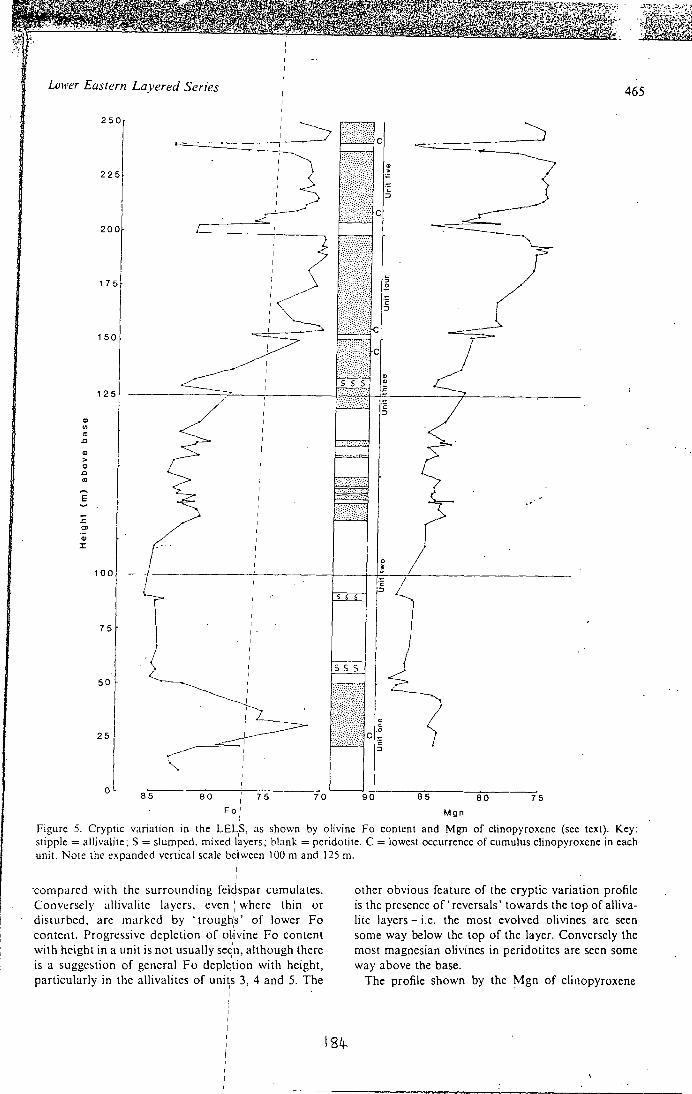
Lmrer Eastern Layered Series 465
225
200
1 7 5
150
125
Q)
"' "' .0
., > 0
.0
"' E
.s::. 0> .,
:I:
100
75
50
25
0
Fo' Mgn
Figure 5. Cryptic variation m the LEL,S, as shown by olivine Fo content and Mgn of clinopyroxene (see text). Key: stipple =allivalite; S = slumped, mixed layers; blank =peridotite. C = lowest occurrence of cumulus clinopyroxene in each unit. Note the expanded vertical scale be ,I ween 100m and 125m.
·compared with the surrounding felcjspar cumulates. Conv~:rscly allivalite layers, even ; where thin or disturbed, arc marked by 'trough;s' of lower Fo content. Progressive depletion of olivine F o content with height in a unit is not usually seen, although there
I
is a suggestion of general Fo depl~tion with height, particularly in the allivalites of uni~s 3, 4 and 5. The
184-
other obvious feature of the cryptic variation profile is the presence of' reversals' towards the top of allivalite layers- i.e. the most evolved olivines are seen some way below the top of the layer. Conversely the most magnesian olivines in peridotites are seen some way above the base.
The profile shown by the Mgn of clinopyroxene
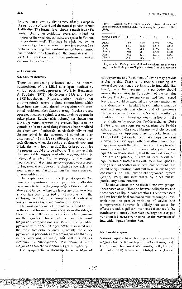
466 I
follows that shown by olivine very clpsely, except in the peridotite of unit 4 and the central' portion of unit I allivalite. The former layer shows a ~much lower Fo content than other peridotite layers, ;and indeed the olivines of the overlying allivalite are richer inFo than the peridotite itself. This may be dplained by the presence of gabbroic veins in this area (sec section 2.c), perhaps indicating that a subsurface gabbro intrusion has modified the chemistry of the cumulates at this level. The situation in unit I is prbblematic and is discussed in section 6.c.
6. Discussion
6.a. Mineral chemistry
There is compelling evidence that the mineral compositions of the LELS have bfen modified by vanous postcumulus processes. Work by Henderson & Suddaby (1971), Henderson (1975) and Bevan (1982) has shown, in Rhum and other intrusions that chrome-spinels generally show corjlpositions ~hich have been extensively altered by reaction with interstitial liquid and other phases present. If such a process operates in chrome-spinel, it seems !i'kely to operate in other phases. Butcher (this volume) has shown that late-stage veins, representing evol~ed liquids in the cumulate pile emplaced along fractures. have modified the chemistry of minerals, particJJarly olivine and chrome-spinel in the surrounding cumulates over distances of 1-2 em. Ifre-equilibratjon can occur over such distances when the rocks are relatively cool and brittle, then with hot interstitialliqJids in porous piles the process should also be effective! This may explain the remarkable constancy of olivi* compositions in individual samples. Further support for this comes from the fact that olivines are never:zoned with respect to Fo, even when co-existing pha~es show extensive zoning, implying that any zoning has been eradicated by re-equilibration.
The cryptic variation profile (Fig. 5) suggests that mineral compositions in a given pe~idotite or allivalite layer are affected by the compositibn of the cumulates above and below. Where the layer~ are thin. or where a layer has been disturbed or slumped in with the
• I
enclosmg cumulates, the compositional contrast is lower than with thick and contin~ous layers.
The most magnesian .clinopyro~ene should be seen as the earliest formed cumulus crystals in allivalites as
I ' these represent the first appearance of clinopyroxene on the liquidus. This is not the case. The most
• • . I . magnesian compositiOns are se~n 111 the poikilitic pyroxene within the unit 2 peridqtite, associated with the most forsteritic olivines. Generally the clinopyroxenes in peridotites are more: magnesian than any in the overlying allivalite, an~ within allivalites intercumulus clinopyroxene lqw down is more magnesian than the first cumulu~ grains higher up.
The sympathetic relationshi~ between Mgn of I
J. W. FAITHFULL
Table I. Liquid Fe-Mg ratios calculated from olivines and chnopyroxenes m selected LELS rocks. using the equations of Duke (1976)
Sample number Fo Mgn L,.., L,.." -------·------------------------- ---·- ------UIA2 79.2 K4.2 O.H75 0.606 U2PI H4.5 l\6.6 0.61) 0.472 U4A3 70.5 78.5 1.395 1.005 U4AI5 70.0 76.1 1.429 1.200 U5A! 76.2 82.1 1.041 0.743 U5A!7 76.6 80.2 1.017 0.872
L,-0 = molar Fe-Mg ratio of liquid calculated from olivine. L"•" =molar Fe-Mg ratio of liquid calculated from clinopyroxene.
clinopyroxene and Fo content of olivine may provide a clue to this. There is no reason, assuming that mineral compositions are primary, why interstitial (i.e. late-formed) clinopyroxene in a peridotite should mirror the variation in Fo content of the cumulus olivines. The clinopyroxenes crystallized from trapped liquid and would be expected to show no variation. or a random one, with height. The sympathetic variation observed suggests that olivine and clinopyroxene exercise a control on each other's chemistry either by equilibration with late-stage migrating liquids in the crystal pile, or by subsolidus Fe-Mg exchange. Duke (1976) gives equations for calculating the Fe-Mg ratios of mafic melts in equilibration with olivines and clinopyroxenes. Applying these to rocks from the LELS (Table I) it can be seen that clinopyroxenes in a given rock have apparently crystallized from more magnesian liquids than the olivines, contrary to what would be expected from the order of crystallization. Apart from demonstrating that the mineral compositions are not primary, this would seem to rule out equilibration of both phases with interstitial liquids as being the final control on mineral compositions. The extent of equilibration is difficult to gauge due to poor constraints on the olivine-clinopyroxene system (Wood, 1976) and interference by other phases, particularly oxide minerals.
The above effects can be divided into two groups: those based on equilibration between solid phases. and those based on liquid-solid reactions. The former seem to have been the final control on mineral compositions, explaining the parallel variation of olivine and clinopyroxene; however, it is likely that subsolidus effects are only significant over small distances (a few centimetres at most). To explain the large-scale cryptic variation it is necessary to consider the movement of interstitial liquids (section 6.c).
6.b. Parental magmas
Various liquids have been proposed as parental magmas for the Rhum layered rocks (Brown, 1956; Gibb, 1976; Dunham & Wadsworth, 1978; Huppert & Sparks, 1980). Recent unpublished work (Forster,
i i
I r r

Lower Eastern Layered Series
"' c .:: 0
90
0 80 u..
I 0
I I
I
I
I I
I
cf
70~----------~------~--10 15 20
% MgO liquid
Figure 6. Variation of Fo content of oliyine primocrysts, with ~-~ MgO of liquid for selected dy;kes analysed by McClurg (unpubl. Ph.D. thesis, Univ. Edinburgh, 1982).
I I I I
unpubl. Ph.D. thesis, Univ. Durhfim, 1980; and McClurg, unpubl. Ph.D. thesis, Uhiv. Edinburgh, 1982) has proved the existence of u'ltrabasic liquids with up to 21% MgO in the Rhum dyke suite. Such
. I magmas would seem rdeal parent magmas for the ultra basic complex, being capable of qrystallizing large amounts of forsteritic olivine witho,ut the enormous volumes of magma required for ~ basaltic parent liquid. :
The relationship between primocryst Fo content and liquid MgO content of dykes analysed by McClurg (unpubl. Ph.D. thesis, lbniv. Edinburgh,
I
1982) is shown in Figure 6. ApplyirW this diagram to the LELS rocks, a liquid of about ,13% MgO would account for the most magnesian ;olivines observed (Fo85 _6). However, this can only pe regarded as a minimum value, as the observed Ilo contents in the LELS are likely to be somewhat loWer than when they first crystallized. An. analysis by JJ E. McClurg of a
I dyke near to this composition is gi1ven in Table 2.
6.c. The formation of the LELS
I I
I I I I
The alternations between peridqtite and allivalite have, since the work of Brown (1956), been ascribed to the repeated replenishment of tHe magma chamber. This is supported by the pattern Or cryptic variation, in which peridotites have more :magnesian olivines than the overlying and underlying allivalites.
Recent work on the behaviq'ur of open-system magma chambers (Huppert & Sp,arks, 1980) suggests that replenishment of a basic magma chamber by picritic liquids would result in ponding of the hot, dense new magma under the lig~ter, cooler residual magma. Olivine crystallizes from the picrite, which
I
converts strongly as it loses h~at to the overlying liquid. As olivine crystallizes, the density of the magma
I
467
Table 2. Analysis of dyke 8622
Major element Trace elements oxides(%) (ppm)
SiO, 45.32 Ni 350 AI,O, 12.92 Cr 751 Fe,O, 12.17 v 333 MgO 12.34 Cu 160 CaO 11.47 Sc 36 Na,O 1.92 Pb 4 K,O 0.14 Rb I TiO, 1.53 Sr 239 MnO 0.19 Ba 24 P,O, 0.13 Th 0
y 19 Zr 94 Nb I La 7 Ce 12 Nd 8
Analysis of dyke from unpublished Ph.D. thesis of J. E. McClurg (Univ. Edinburgh, 1982), with permission. A similar liquid may have been parental to the LELS.
in the lower layer decreases. Eventually the temperatures and densities of the layers approach equality, and the boundary between them breaks down. This marks the end of peridotite formation. The fractionation of picritic-tholeiitic melts is often marked by a density minimum at around the point where plagioclase begins to crystallize in quantity (Stolper & Walker, 1980; Huppert & Sparks, 1980). Thus the magmas from which the more fractionated allivalites (units I, 3, 4, 5) crystallized may have been denser than those which formed the more primitive troctolitic types (unit 2, most of the upper ELS units). A picritic melt emplaced into cooler, more evolved magma will thus mix more quickly than one emplaced into hotter magma with a composition around the density minimum, due to the lower density contrast. It will also lose heat faster; this may explain the abundance of elongate olivine crystals in the peridotites of units 4 and 5, as such habits are encouraged by fast cooling (Donaldson, 1976).
If the picritic liquid is denser than the interstitial liquid in the underlying crystal pile, it may sink into it, displacing the evolved liquids (Tait, Huppert & Sparks, 1984; Sparks et a/., this issue). This would seem to be a potent mechanism for producing the reversals in cryptic variation seen at the top of allivalites, the olivines re-equilibrating with the new Mg-rich magma. Reversals are small or absent at the tops of unit 3 and unit 4 allivalites; perhaps the density of the interstitial liquid in these evolved cumulates was such that convective exchange with the overlying picritic liquid was not possible. A problem here is the large reversal shown by unit I allivalite which, given the evolved nature of the olivines, might be expected to have had interstitial liquid as dense as that in units 3 and 4. However, unit I allivalite shows evidence for early (cumulus) Fe-Ti oxides (section 3.b). Early crystallization of such phases may have caused a
468
continuous decrease in density with fractionation, allowing the picritic liquid to sink in. Conditions of
higher f0 , could account for such behavi1
our. Such
early removal of Fe from the magma might also
explain the magnesian character of the clin~pyroxenes in unit I allivalite. I
The model of Tait, Huppert & Sp~rks (1984) predicts that while evolved orthocumulates are
forming at the magma chamber floqr, evolved
adcumulates will be forming at the roof. It is interesting to note that evolved adcumulates (including
the pigeonite-bearing xenolith) are assbciated with
roof- or wall derived xenolithic ma:terial. This I
assemblage also includes thermally met.amorphosed
amygdaloidal basalt, suggesting that I the Rhum
magma chamber may have been in ~ontact with
Tertiary basalts. I The LELS rocks are in general less ul~rabasic than
those elsewhere in Rhum, both in t'erms of the
abundance of peridotite and in terms ,~f the rather
more evolved mineral compositions. This may be due I
to replenishment by smaller pulses of picritic liquid,
which would crystallize less peridotite and allow the
accumulation of lower-temperature, more evolved
cumulates. The frequent emplacement Of large picritic
pulses would, in addition to producing! large volumes
of peridotite, tend to maintain the chai11ber at a high temperature, thus giving the primitive compositions
typical of the upper ELS cumulates. i I I
Acknowledgements. This work was ca~ried out under N.E.R.C. grant No. GT4 80 GS25, at Du,~ham University. Thanks are due to Dr C. H. Emeleus. who supervised the project, and provided much helpful advice. Alan Butcher, lain Young, Johannes Volker and SteV:e Tait helped in discussing many aspects of the work. Janet McClurg kindly allowed the use of some of her data. Spec
1ia1 thanks are due
to Ms. Cathryn Burge for assistance, not !east in typing and in the preparation of diagrams.
References I
BAILEY, E. B. 1945. Tertiary igneous tectonics of Rhum. Quarterly Journal of the G;ologicai Society of London 100 165-91 ;
' . I
BEVAN, J. C. 1982. Reaction rims of prthopyroxene and plagioclase around chrome-spinels in olivine from
I I
I I I I I I I
I I I I
'
187
-·· ...... ~ l( .~ ·-= '' ;;--
Lower Eastern Layered Series
Rhum and Skye. Contributions to Mineralogy and Petrology 79, 124-9.
BROWN, G. M. 1956. The layered ultra basic rocks of Rhum, Inner Hebrides. Scotland. Philosophical Transactions of the Royal Society of London B 240. 1-53.
BUTCHER. A. R. 1985. Channelled metasomatism in Rhum layered cumulates- evidence from late-stage veins. Geological M aga:inc 122. 503-1 ~.
BUTCHER, A. R., YOUNG. l. M. & FAITHFULL, J. W. 1985. Finger structures in the Rhum complex. Geological Magazine 122. 491-502.
DO!'>ALDSO:-:, C. H. 1976. An experimental investigation of olivine morphology. Contributions to Mineralogy and Petrology 57, 187-213.
DUNHAM, A. C. & WADSWORTH. W. J. 1978. Cryptic variation in the Rhum layered intrusion. Mineralogical Magazine 42. 347-56.
DUKE, J. M. 1976. Distribution of the period four transition elements among olivine. calcic clinopyroxene and mafic silicate liquids: experimental results. Journal of Petrology 17, 499-521.
Gms. F. G. F. 1976. Ultrabasic rocks of Rhum and Skye: the nature of the parent magma. Journal af the Geolagica/ Society of London 132. 209-22.
HARKER. A. 1908. The Geology of the Small Isles ()f Inverness-shire. Memoir of the Geological Survey of Scotland, 21 0 pp.
HENDERSON, P. 1975. Reaction trends of chrome-spinel on Rhum. Geochimica et Cosmochimica Acta 39. 1039-44.
HENDERSON. P. & SUDOABY. P. 1971. Nature and origin of the chrome-spinel ofRhum. Conrrihurinns to Mineralogy and Petrology 33. 21-31.
HUPPERT, H. E. & SPARKS. R. S. J. 1980. The fluid dynamics of a basaltic magma chamber replenished by influx of hot. dense. ultra basic liquid. Contrihutiom to Mineralogy and Perrology 75, 279-89.
PALACZ. Z. J\.""1984. Isotopic and geochemical evidence for the evolution of a cyclic unit in the Rhum intrusion. north-west Scotland. Nature 307. 618-20.
SPARKs, R. S. L HuPPERT, H. E., KERR. R. C.. McKE~'>ZIE. D. P. & T AIT, S. R. 1985. Postcumulus processes in layered intrusions. Geological Maga:ine 122. 555-68.
STOLPER, E. & WALKER. D. 1980. Melt density and the average composition of basalt. Conrrihwions ro Mineralogy and Petrolog.1· 74, 7-12.
TAIT, S. R., HUPPERT. H. E. & SPARKS. R. S. J. 19R4. The role of compositional convection in the formation of adcumulate rocks. Lithos 17. 139-46.
WooD. B. J. 1976. An olivine-dinopyroxene geothermometer. Contrihutions ro Mineralagy and Petrology 56. 297-303.
I
I

I Geo/. Mag. 122'(5), 19/J5, pp. 491-502. PrinJed in G,'reat Britain 491
'
Finger stru¢tures in the Rhum Complex I I
ALAN R. BUTCHER,i JAIN M. YOUNGt & JOHN W. FAITHFULLt
•. Department ofiGeology, University of Manchester, M 13 9PL. U.K. t Department of Geologx. University of St Andrews, St Andrews, Fife, Scotland. U.K.
j: Department of Geological Sciences;, University of Durham, Science Laboratories, Durham, DH I 3LE, U.K. '
( Rece('ved 2 November 1984; accepced 13 March 1985)
' ; Abstract - Finger-like protrusions of peridotite are developed on Rhum where peridotite is overlain by allivalite. These structurd, which were described by Brown as ·upward-growing pyroxene structures', are found in the fo\lowing environments: at the main intra-unit junctions; along the upper surface of subsidiary peridotit~s in certain allivalites; and along the lower surface of allivalite blocks in some peridotites. I
The structures generally take the form of parallel-sided or tapering protrusions with circular cross-sections. The tops of fingers are conical or hemispherical in shape. Typical dimensions are: finger amplitude, 2-5 em; finger di~meter. up to 3 em; and finger wavelength, 5-10 em. Peridotite in the finger is modally and textu~ally similar to the underlying layer, varieties range from feldspathic peridotite to dunitic peridotife. In the field the fingers apparently cut through layering. laminae and lamination without any assoCiated disruption of the planar structures.
Two contrasting mechaniims of formation are discussed: vertical deformation of crystal mushes, and metasomatic replacem~~t. On balance. we prefer to interpret the fingers as evidence for the· replacement of pre-existing/allivalite by secondary peridotite. Replacement was achieved by pore magma from the underlying peridotite migrating upwards into the overlying allivalite, in response to compaction. This pore o1agrna was able to resorb plagioclase but crystallize olivine and pyroxene in its place. !
I
1. Introduction ' I '
Recent detailed mapping on Rhu,m has established that the layered intrusion can be en:visaged as an early well layered series of rocks, no,w comprising the Eastern Layered Series (ELS) .and Western Layered Series (WLS), intruded by a later! transgressive body of largely unlayere~ ultrabasic rqcks comprising the Central Series (CS) (unpub. Ph/D. theses by J. E. McClurg, 1982, and J. A. Volker, 1983. Univ. Edinburgh). Tht: layered serie,~ may be further subdivided into major cyclic unitsi(Brown, 1956): such a unit is defined as an olivine-rich lower laver (peridotite) overlain by an upper blagioclase-rich layer (allivalite). !
Conventionally, the cyclicity /of the Rhum stratigraphy has been interpreted as ,:the result of periodic replenishment of the magma chamber (Brown, 1956; Wadsworth. 1961), although Young (unpub. Ph.D. thesis, Univ. St Andrews, 1:984) has tentatively proposed contemporaneous crystallization of different types of cumulates in a ver,tically zoned magma chamber. The basic assumption in the interpretation of the layers has been that the pfesent lithostratigraphy is essentially a primary featyre. However, compositional modification by pervasive or channelled
' ' Present addresses: • Institute for Geological Research on the Bush veld Complex. University of Pretoria, Hillcrest, Pretoria, 0002, Republic of South Africa. t Dcpartfjlent of Geology, University of Leicester. University Road. Leicester LEI 7RH. U.K.
'
1'3'8
metasomatism may have occurred (J. A. Volker, unpub. Ph.D. thesis, Univ. Edinburgh, 1983; Butcher, this issue).
In this paper we describe structures, termed 'finger structures', which indicate that modal replacement of allivalite by peridotite has occurred on Rhum, on both a local and massive scale, producing rocks texturally and compositionally indistinguishable from presumed cumulates in the intrusion. The importance of this conclusion for interpretations of Rhum lithostratigraphy is assessed and a tentative, qualitative model for the formation of these secondary rocks is proposed.
2. The finger structures
The contacts between peridotite and overlying allivalite on Rhum are commonly characterized by finger-shaped protrusions of peridotite into allivalite. These structures were first described by Brown ( 1956), who compared them to the 'fingers of an outstretched hand' and named them upward-growing pyroxene structures. Since they do not necessarily contain pyroxene, and have not formed by pyroxene growing upwards, we propose that they be called 'finger structures' on account of their geometry. This is in keeping with the terminology used by Robins ( 1982) for describing similar structures in the Lille Kufjord intrusion.
Finger structures are commonly developed through·

492
out the ELS and CS, but only three areas have been studied in detail: the Hallivai-Askival,
1
area (ELS); the Miilishal area (CS); and the Long Loch area (CS).
I
Fingers have not been found in the WLS. I
2.a. The Hallivai-Askival area
Figure I summarizes the principle! localities where finger structures are developed. Jhe three main environments are: (i) along the :main intra-unit contacts (e.g. Units 6-11); (ii) alongithe upper surface of subsidiary peridotite layers in certain allivalites (e.g. Units 2, 8, 12, 13, 14); and (iii) along the lower surface of allivalite blocks in peridotite (e.g:. Units 9, 10, II). Because fingers at intra-unit contac:ts are the same as those in (ii) above, only fingers frorrt environments (ii) and (iii) are described.
1
I
2.a.l. Fingers associated with subsidiar,\· peridoTites I
Unit 2, Alit nam Ba. Unit 2 of t~e ELS contains a number of subsidiary peridotites ~ithin the allivalite, best exposed in the Alit nam Ba (fig. 1).
Figure 2a shows that the alliyalite (6.5 m thick) contains three thin peridotite laye~·s. Each of these has a sharp planar base and a fingere~ top, although the fingers are rather small ·(1-3 em !in amplitude). The allivalite above the lowest peridotite has well
I developed recumbent slump fold~- these are sharply cut across by the fingers (Fig. 3).:
To the north the peridotites thi.~ken somewhat, and deformation becomes more marked with the peridotite
I
layers becoming locally discontin'uous due to loading, with flame structures of alli~alite injecting the peridotites. Fingering is more prominent on the upper surfaces of the peridotite layers t,han it is to the south.
A few tens of metres to the north the allivalite presents a different spectacle. Th:e upper part has been extensively disrupted by finger development, with merging of subsidiary peridotit~s leaving only a few relic fragments of plagioclase-cJmulate (Fig. 2 b). The peridotites often show' inverted!mushroom' style load structures, the upper surfaces of which show the development of fingers. i
' I
Unit 8, northeast Askival Platf11au. The fingers at this
locality (Fig. I) are the same as Brown's (1956) "upward-growing pyroxene st1ructure'. A schematic strike section of the exposure is given in Figure 4.
At the southeastern end. up: to six minor peridotite horizons can be distinguished. Finger structures are
. I developed along the upper c,ontacts of layers A, B (Fig. 5 a, b), E and F. The lo,wer contacts are either planar or slumped (load str~ctures?). Towards the northwest, exposure is incomplete and only the bottom two layers (A and B) are founb. Both layers thin away towards this direction and m~rge with the allivalite.
\'39
A. R. BUTCHER, I. M. YOUNG & J. W. FAITHFULL
Close inspection of weathered surfaces shows that the fingers cross-cut the feldspar lamination in the allivalite (Fig. 5 b). Peridotite in the finger is texturally similar to the underlying layer (a general increase in clinopyroxene content is apparent in both at the northwestern end of the section). Layer B (figured by Brown, 1956. plate 2. fig. 20) contains fingers of variable orientation: some are vertical; others preferentially lean in one direction.
Thin sections of samples from layers A and B (Fig. 6) show that the finger structures are formed of tabular olivines enclosed by large poikilitic clinopyroxene crystais (Brown, 19 56). Plagioclase only occurs as rare interstitial patches.
Brown (1956) made several important microfabric observations on fingers from this locality. He noted that the tabular olivines near the edge of the finger are orientated parallel to the periphery of the structure, while in the core they are random. as is seen in Figure 6. He also established that tabular crystals of olivine and plagioclase in the overlying allivalite are orientated roughly horizontal, except at the contact with the structure where they are rotated out of alignment and now lie sub-parallel to it. This can also be seen in Figure 6 (the deflection of the lamination is not sufficiently dramatic to be picked out on a weathered surface; see Fig. 5b). Peridotite I em below the base of the finger in Figure 6 is a typica).; well-laminated olivine cumulate. At distance's greateli'han 3 em below the finger, the cumulus olivines change in shape from tabular to anhedral.
Unit 14, west Hallil·al. The allivalite section of Unit 14 directly below the summit of Hallival contains several layers of olivine cumulate, but all are classed as belonging to one unit for practical reasons (after Brown, 1956). A measured section through the allivalite on the western side ofHallival (Fig. I) is given in Figure 7 a.
The main intra-unit junction is gradational but in the overlying allivalite the subsidiary peridotites all have sharp contacts (except where indicated in Fig. 7 a). Finger structures were recorded hy Brown (1956) in this part of Unit 14: Figure 7a shows they are ubiquitous, and only three peridotite horizons do not contain them along their upper contacts. Some of the structures are remarkablv regular and finger-like (e.g. Fig. 7b,c); others are highly irregular (Fig. 7d).
Three different peridotite horizons have been sampled (Fig. 7a; samples HF9. HF4. HF3) and all show that the Unit 14 fingers are texturally unlike those already described from Unit 8. Firstly. the finger peridotite consists of anhedral rather than tabular olivines. Secondly. the clinopyroxene grains (and occasional plagioclase) which enclose the anhedral olivines do not form well-developed oikocrysts. Thirdly, the allivalite is unlaminated in all samples.

' I I I
Finger struc!Ures in the Rhum Compte~
b
D Allivalite
493
.. , .,::,-':.Coire '-.
0 Conformable· (' l sheets of allivalite
[] Peridotite
A ':>· . .-::·;: non \ ··:·fGrunnd:
-~~~~~~~~~~~~~~~~~~~~---r~~~~~~--~~~~-- ••
GEOLOGICAL SYMBOLS
........-- LitholoQicol boundary observed
LithOioQical boundary inferred certain
~~ Litholoqicol boundary
mferred uncertain
,4,.-.N'; Litholoqical boundary Qrodotionol
10 Dip of loyerin9 y
/I Faull f / U9 refers to Brown's
' (1956) units I I
H = Hall ivai I 105
A= Askivol I
' FINGER STRUCTURES DEVELOPED ALONG:
i ~ main intra-unit contoc1 11
s - upper surface of subsidiary pendotiie
b- underside of allivalite block /
0
km
Scale I: 10,000
0.5
i
I
'
39
40
Figure I. Geological map of the H~llival and As kiva! area showing the principal localities where finger structures are developed. I
' I
I I
2.a.2. Fingers associated with all(valite blocks I
The peridotite sections of Un,its 9, 10 and II contain impersistent horizons of allivalite blocks in northwest Caire Dubh, southeast Coir~ Dubh and the Askival
I
32 ' I I I
I 190
Plateau area, respectively (Fig. 1). The orientation of layering in the blocks is similar to that found in the surrounding peridotite suggesting they are not xenoliths but instead relic fragments of an originally continuous allivalite layer (or layers). The blocks all
GEO 122

494
1m
a b
Figure 2. Stratigraphy of Unit 2 allivalite at two localities (a, b) in the Alit nam Ba. Black, peridotite; blank, allivalite. See text for details.
Figure 3. Finger structures cutting slump folds in Unit 2, Alit nam Ba.
SE
--:....: =-c
- - (
'-- ' [
0
\/Wtocal Scole
lm
• Per adol ll t
Q A IIIVQil tt
NW
-- - z ~ .... -=--- -
--~ ~ --- ~ ~-·-~=-~~ ~- ~~~. _II ..... lllj ~~~~~-- •_•_ •-~1"'-:--:•~·--:...,..1 ~-•-I I Figure 4. Schematic strike section of Unit 8 allivalite, northeast Askival Plateau, showing structures developed at the upper contacts of subsidiary peridotite horizons. Lateral distance represented by the section is approximately 100 m (see Fig. 1).
/91
A. R. BUTCHER, I. M. YOUNG & J. W. FAITHFULL
Figure 5. Finger structures associated with subsidiary peridotite layer B in Unit 8 allivalite, northeast Askival Plateau. (a) Fingers are developed along the upper contact, while the lower contact is planar. Scale: hand lens. 3 em long. (b) Close-up of the fingers in (a). The weathered surface of the overlying allivalite shows igneous lamination of cumulus olivine and plagioclase grains.
have highly irregular lower surfaces which are invariably finger-shaped (Fig. 8). Some have planar upper surfaces containing a chrome-spinel layer which i continues undeformed in the surrounding peridotite / up to 1.5 m away from the block (Fig. 8).
1 2.b. The Minishal area I The northern margin of the CS form~ a broad tongue-shaped area east ofMinishal (Fig. 9) consisting largely of undifferentiated peridotite. cut by intrusive ultrabasic breccia zones and a late gabbro (J. E. McClurg, unpub. Ph.D . thesis, Univ. Edinburgh, 1982).
At a locality southeast of Minishal (Fig. 9). a cliff exposure reveals a breccia zone containing a layer of allivalite (maximum thickness 3.5 m), which tapers out to the east and is unexposed at the western end. The layer is surrounded by a matrix of feldspathic peridotite. Along the lower contact, the matrix
.

Finger structures in the Rhum Complex
Figure 6. Photomicrograph of sample GMBFC; a finger structure developed at the top of peridotite layer A, Unit 8 allivalite, northeast Askival Plateau. Crossed polars; field of view 2 em wide.
peridotite protrudes upwards into the allivalite in -the form of impressive finger structures (some up to 50 em in amplitude). The upper contact does not show these structures but it is highly irregular. Diffuse subhorizontallayering is present throughout the allivalite; most of the fingers are normal to the layering, although some have been found to lean preferentially in one direction.
Prominent subvertical channels cut through the allivalite layer but these are interpreted as largely a weathering phenomenon related to the presence of joints or other planes of weakness. It is possible however, that some channels may have originally been filled by pipe-shaped peridotite protrusions from the layer below, and that the peridotite has since been removed by preferential weathering.
A further interesting feature of this exposure is that at the eastern end there are two fragments of allivalite in the peridotite about 0.5 m below the layer. Both fragments have planar upper contacts, finger-shaped lower contacts, and are completely surrounded (in 2-D) by peridotite .
A specimen of a peridotite finger taken from the middle of the exposure consists of anhedral olivine; hydrous intercumulus phases (brown amphibole, brown mica; 1- 5 vol. % ); intercumulusclinopyroxene; and secondary alteration minerals (chlorite, serpentine) . Plagioclase was detected in some thin sections. The allivalite surrounding the finger is weakly laminated; a few plagioclase tablets at the contact are deflected upwards.
I ~2
495
2.c. The Long Loch area
On the western shores of Long Loch (Fig. 9) there are spectacular sections through a well-layered sequence of the Central Series, mapped by J. E. McClurg (unpub. Ph.D. thesis, Univ. Edinburgh, 1982) as belonging to the Long Loch Member (or Long Loch Group of J. A. Volker, unpub. Ph.D . thesis, Univ. Edinburgh, 1983).
A schematic strike section of the sequence west of the loch is given in Figure 10. Three compositionally distinct units are shown. Unit A at the base is an unlayered olivine-rich cumulate. This is overlain by an allivalite (Unit B) containing several modally graded layers (olivine-rich base, plagioclase-rich top) . Unit C is a layer consisting of normally size-graded fragments of peridotite set in a feldspathic matrix . A slumped horizon of feldspathic peridotite (Unit B, a) occurs near to the top of Unit B.
Exposure is sufficiently good to be able to examine in detail the junctions between each unit. Figure 10 indicates the various types of structure observed . They include :
Flame structures : these are flame-shaped protrusions of allivalite into overlying peridotite. They are developed at the contact between Units Band C, and also at the interfaces between individual graded layers in Unit B (flames are omitted from Unit Bin Fig. 10 for clarity).
Finger structures : these occur at the Unit A- B junction (Fig. 11); along the upper surface of Unit B, a; and within individual graded layers in Unit B.
Finger structures in Unit B can be seen to develop across the section from north to south. At the northern end, there are up to 7 modally graded layers. Laterally, however, the olivine-rich bases of some layers start to develop finger-shaped interfaces with the overlying plagioclase-rich portion of the layer (Fig. I 0), but only where the gradation from one into the other takes place abruptly (across a zone less than I em in thickness). In the middle and southern end of the section some peridotite fingers extend right through the plagioclase-rich section and coalesce with the olivine cumulates at the base of the overlying graded layer. Layering in the allivalite near to the transgressive finger structures is always undeformed.
Samples suitable for detailed analysis of the Long Loch structures have not been obtained because of extraction difficulties, but a thin section of the Unit A- B contact shows the peridotite is petrographically similar to the Minishal structures. Intercumulus amphibole, mica and clinopyroxene enclose anhedral olivines. The allivalite in this section is unlaminated.
32-2
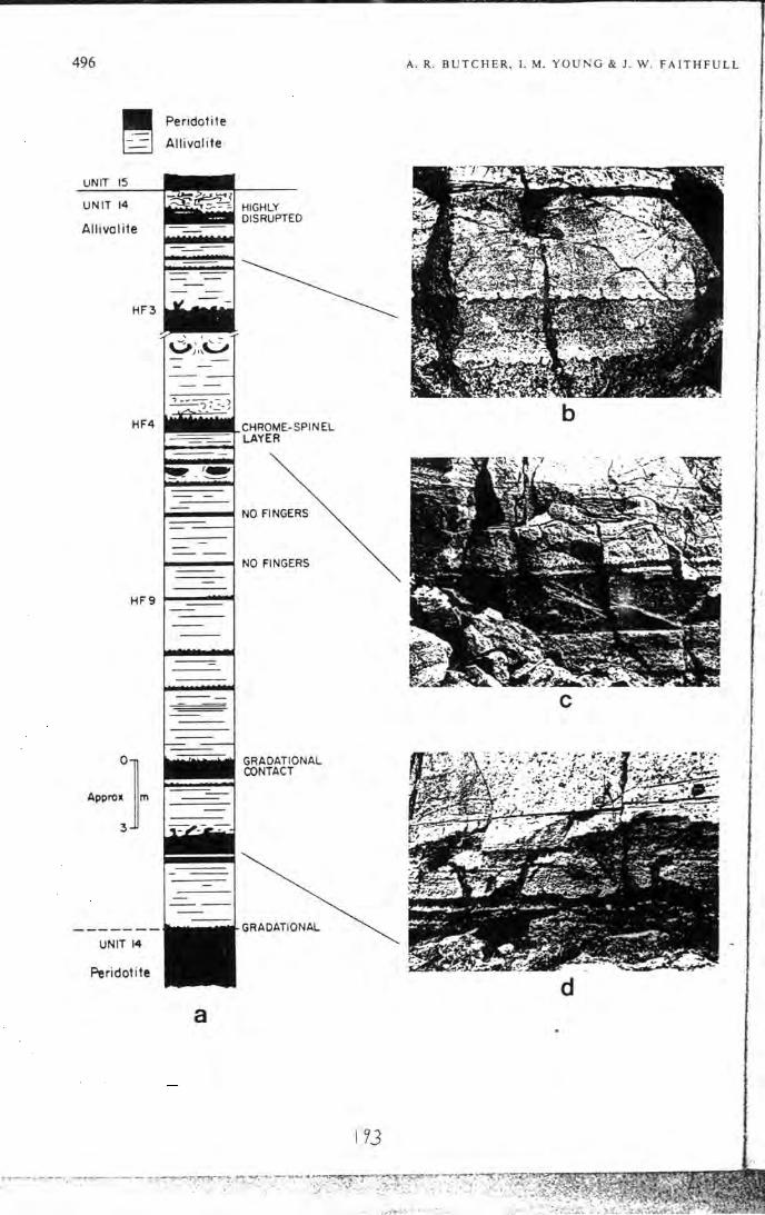
496
UNIT 15
UNIT 14
Allivalite
HF3
HF4
Peridotite
Allivalite
HF9 1--~~
UNIT 14
Peridotite
a
A. R. BUTCHE R, L M. YOUNG & J . W . FAITHFULL
b
NO FINGERS
c
GRADATIONAL
d
I ~3
. .-~ .... );,t~~ · .•.. ;. ·..... .. .

' .
I
I I I I I
Finger structures in the Rhum Comp,fex
I
Figure 8. Block of layered allivalite in felpspathic peridotite, Unit II. Askival Plateau. A chrome~spinel layer (c) is present along the upper surface of the block which extends into the surrounding peridotite. ,!
I I
497
3. Mineral compositions
A preliminary microprobe study has been carried out on samples of six different finger structures, and the results are summarized in Figure 12.
3.a. Olivine and clinopyroxene
All samples analysed show there are no significant differences in the compositions of olivine and clinopyroxene between finger peridotite and the overlying allivalite. There are also no systematical changes in the composition of these minerals either with position within a finge'r (e.g. Minishal; A, B) or with position in peridotite below a finger (e.g. Unit 8; 1-3). All olivine is unzoned; clinopyroxene is normally zoned at the extreme margins of some grains (only core compositions are given in Fig. 12).
Intrusion Gabbro
Peridoti~;- T Allivalite = onoue
/ G~anophyre
Torridonian
~-.:...:..w...'-'-'-.:...:."'-'-:....:..:..:.!..:..:..;'-'-'-~'-'-I.:..:..:...:...;~.;.:...:...:..:...::.:___Vt;:l Lewisian Gneiss
I
Figure 9. Sketch map of the geology of the Minishal and Long Loch areas, modified after J. E. McClurg (unpub. Ph.D thesis, Univ. Edinburgh, 1982). Symbols!: LLF, Long Loch Fault; MRF. Main Ring Fault. Arrowed box indicates the position of the Minishallocality referred to ip the text; rectangular box shows the area covered by Figure 10.
I
Figure 7. Finger structures in dnit 14 allivalite, west Hallival. (a) Sketch stratigraphic section through Unit 14 allivalite, showing the contacts along which finger structures are developed (schematically represented by bulges along upper surfaces of subsidiary peridotite layers). (b)!Two peridotite layers with weakly developed finger structures along their upper contacts. (c) Regular shaped finger struct\/res. The lower contact of the peridotite is characteristically planar. Note the complex slump structures in the allivalite abovs the fingers, and the feldspathic veins cutting both peridotite and allivalite. Scale: 50 pence coin. middle of exposure. (d) lr~egular shaped protrusions of peridotite (generally plate-like), developed above a well-layered subsidiary olivine cumulate.
I
I I I I I
I 194-

498
s 0
[
VEIIT . SCALE
1m
~ -~- --:-~. --~ ----
- ~ -~-
Units ..c;: =-· C Fragmental (size graded) 8 Allivalite (modally graded)
(up to 7 layers) Ba Feldspathic peridotite A Peridotite (dunite in places)
(unlayered)
A. R . BUTCH ER, I. M. YOUNG & J . W . FAITHFULL
N
c
Figure 10. Schematic strike section of the well-layered CS sequence west of Long Loch. Lateral distance represented by the section is approximately 0.75 km.
Figure II. Peridotite fingers cutting layered allivalite. Unit A-B contact, Long Loch area (see also Robins, 1982, fig. 6).
3.b. Plagioclase
Relative to plagioclase in the allivalite, finger plagioclase shows a greater compositional range, and is generally more Na-rich .
4. Summary
The following general observations have been made on Rhum finger structures:
(a) Fingers only develop where peridotite is overlain by allivalite. From their present lithologies this indicates a positive or gravitationally stable density stratification, i.e. the relatively denser peridotite is at the bottom.
(b) The contact between the peridotite and the allivalite is always exceptionally abrupt. Fingers do not form along gradational contacts.
(c) Only the upper surface of the peridotite layer
\ 9 s-
develops fingers. The lower surface is characteristically planar.
(d) Fingers are found in a variety of environments: (i) at the main intra-unit contacts; (ii) along the upper surface of subsidiary peridotites in certain allivalites; (iii) along the lower surface of allivalite blocks in some peridotites .
(e) The geometry of the structures at any given locality is often remarkably consistent. They generally take the form of parallel-sided or tapering protrusions with circular cross-sections. The tops of fingers arc conical or hemispherical in shape. Typical amplitudes for most fingers are 2-5 em; diameters up to 3 em. Distances between individual fingers are also regular ; typical wavelengths measure 5- 10 em . The long axis of the finger is usually orientated normal to the layering, although some have been found that are vertically orientated or preferentially lean in one direction.
However. not all of the structures are finger-shaped : pipe-like structures (2m long : diameters up to 10 em) and plate-like structures also occur. On encountering more mafic layers in the allivalite. fingers sometimes widen , but have never been noted to narrow. o consistent correlations between finger geometry and the thickness, lithology or texture of the underlying peridotite layer have been found .
(f) Inspection of weathered surfaces suggests that peridotite in the finger is modally and texturallr similar to the underlyi ng layer. Varieties range from feldspathic peridotite to dunitic peridotite.
(g) Finger structures cross-cut slumped allivalite and therefore post-date slumping events in the feldspathic cumulates. A finge r in Unit 2 (ELS) is cut by a late-stage ultrabasic vein.
(h) In terms of mineral chemistry, finger peridotite and overlying allivalite are essentially the same in composition, except for plagioclase which is more Na-rich in the finger.
r I
I
f I

' Finger structures in the Rhum Com/J!ex 499
Location Parts of finger
cove red ~y i thin sect ion
OLIVINE Fo
ALLIV. FING. A
CPX Mgr
F
PLAGIOCLASE An
A F
Minishal (CS)
~ _M~I:_N_B_B __ ~8-4._3~8_4_._24-8_4_.9-+_8_6_.2~a_s_.4_-_a2_.8~-76_._1-6_1_.7~ I~ MiN 8 A 84.8 84.9 - 86.0 85.9-83.3 80.5-61.6 ~ I
~ H F3,1 83.6 82.7
J~~ ~L -H-'-:~-3....:.,-z --+--82-.9-+--8-2-.8-+-8-5-. 0---+-85-. 0---1-8-8-.4---8-5.-2-+---8-7-.3--7-8-.8~ 85.5 -- 86.5-84.5 84.5-69.2
Unit 14 Allivalite
~ H/F4 84.7 84.2 85.8 85.9 89.5-85.9 88.2-64.2
Unit II
Allivalite
Unit 8 Allivalite
I
84.5
82.0
81.0
85.2 88.5
81.7 86.1
82.0
80.9 83.8
87.8 84.4-82.2 77.2-578
85.1 85.2-83.3
85.0 82.0-75.3
85.4 85.2-80.1 854-71.5
Figure I 2. Summary of electron micr0probe data of finger structures from the Minishal area (CS) and the Hallivai-Askival area (Units 8, I 1 and 14). Fo and ~'gr, 100 Mg/(Mg+ Fe) ratios. An, 100 Ca/(Ca+ Na) ratio: values given are ranges of plagioclase 'core' compositions. Analyses were made on a modified Cambridge Instrument Company Geoscan fitted with a Link Systems model 290-2KX energ~-dispersive spectrometer. Average compositions for all phases were determined from at least 5 analysed spots of 5 different qystals.
5. Discussion
In a recent paper, Robins (1982) has suggested an origin for the finger structures in ~he Lille Kufjord and Rhum intrusions. His conclusioq is that they are not deformational structures but formed by metasomatic replacement of allivalite by peridotite.
In the discussion below, three ,different mechanisms of formation are considered in: the light of the new field, textural and mineralogical observations on the Rhum fingers: i
(a) deposition of allivalite on an irregular peridotite floor; :
(b) deformation of crystal m.~shes; (c) metasomatic replacement'.
I
' ' I
S.a. Deposition on an irregular flo~r I .
One possible explanation of th,e Rhum fingers ts that they represent the morpholog~ of the peridotite floor prior to deposition of the allivalite. This might explain fingers with small amplitudes (e.g. Fig. 7 b, c) but not pipe-like structures or other :more complex shaped
. I
19t,
protrusions (e.g. Fig. 7 d). Also, transgressive relationships suggest the fingers formed after deposition of the allivalite and not before it (Figs 3 and II).
S.b. Vertical deformation of a crystal musb
A more plausible mechanism is that the finger structures formed by vertical deformation of an unconsolidated olivine cumulate into overlying, relatively more consolidated, allivalite. However, this is extremely difficult to reconcile with: (i) the overwhelming field evidence that layered allivalite near to cross-cutting fingers is apparently undeformed; (ii) the structures having formed at contacts where there is a normal density gradient (as suggested by the present rock densities). Analogous deformation structures in layered clastic sediments always develop in reverse density gradients (Anketell, Cegla & Dzulynski, 1970). The morphology of the fingers is also different from the mushroom-like load structures described by Thy & Wilson (1980) from the Fongen-Hyllingen intrusion.
500
5.b.l. Lack of deformation, I
Deformation is not obvi~>US at outcrop scale (Fig. II), but there is some evidence from thin sections that disruption of laminated ~rystals has taken place. For example, in Unit 8 tabular olivines in the finger lie parallel with the margin~ of the structure, whereas in the peridotite below the finger they lie parallel with the general orientation ofthe\layering. Also, lamination in the aJiivalite is deflected upwards at the finger contacts. However, we consider th:e deformation to be on too small a scale if the fingers had fonned by a process involving only diapiric i:ntrusion of peridotite into allivalite. i
I
5.b.2. Relative density I
I
Lee (1981) has described '~imilar structures from the Bushveld Intrusion which; formed in normal density gradients. The structures, termed 'flames' rather than
I
'fingers' by Lee (1981),: occur where anorthosite overlies chromitite or pyroxenite; and norite over harzburgite or chromitite. Because these structures are similar in many respects t:o those in reverse density gradients in clastic sedime'nts, Lee has inferred that interstitial liquid played: an important part in controlling the relative density and viscosity of the adjacent cumulate layers. ;
A similar mechanism fo'r the Rhum structures is suggested by the recognitio~ of a density minimum in the MORB liquid line of descent (Stolper & Walker, 1980; Sparks, Meyer & Sig~rdsson, 1980). Huppert & Sparks (1980) consider tha!t liquids parental to the Rhum peridotites were picr\tic and those parental to the allivalite were basaltic. \Assuming this to be the case, liquid trapped within t~e olivine cumulates must initially have become less dense on fractionation of olivine, whereas that trapp~d in the allivalites must initially have become more\ dense on fractionation. Thus, it is possible that liqJ_id present in the olivine cumulates was initially, or beqame, less dense than that in the feldspar-rich cumulate~. Field evidence (section 2.a.l) indicates that the aJljvalite contained a low porosity at the time of finge'r formation (i.e. fingers post-date slumping and lami~ation). Calculations by one of us (IMY) suggest that an allivalite mush containing, for example, 30% interstitial liquid will
. only be more dense than a peridotite mush if the latter contains 80% liquid or mo~e (the densities of the liquids in the allivalite and peridotite are assumed to be 2.75 and 2.70 g/cm 3
, resp~ctively). Unreasonably large amounts of interstitial liquid are needed in the peridotite (up to 80/'~) before gravitational instability can be induced. ·
Although loading of two ctystal mushes with the properties o~tlined above o~ercomes the relative density problem, this mechanism cannot account for the field evidence that peridotite has apparently been
I
197
·=-"'
A.-K: !lUTCHER, I. M. YOUNG & J. W. FAITHFULL
generated at the expense of allivalite, and that fingers transgress allivalite layers causing negligible distortion in comparison with their size. We therefore believe that finger formation requires some mechanism in addition to simple loading of crystal mushes.
S.c. Metasomatic replacement
This involves the selective replacement of pre-existing allivalite by secondary peridotite within the crystal pile. Perhaps the most attractive feature of metasomatic replacement as a model for finger formation is that it may take place on a volume-for-volume basis (Irvine, 1980).
S.c.! . . Mechanism
In this model we envisage a situation just prior to the finger formation event where a peridotite layer of high porosity was overlain by an allivalite layer of relatively low porosity. We assume the interstitial liquid in the peridotite at that time was lighter than that in the overlying allivalite (section 5.b.2).
We now suggest the two layers underwent compaction. Compaction was most effective in the peridotite because of the loosely packed crystal framework and the lower density of the interstitial melt (McKenzie, 1984); thus liquid in the peridotite was driven upwards into the allivalite in the form of fingas. Beca.use this liquid was not in equilibrium with the allivalite, this would result in resorption of both feldspar and olivine in the allivalite until all of the feldspar was consumed, assuming strictly isothermal conditions. However, if the peridotite liquid was relatively hotter than that in the allivalite mush, cooling of this liquid as it was expelled upwards would allow feldspar alone to be resorbed and olivine to crystallize (Bowen, 1928; McBirney, 1979). In either case resorption of feldspar would be accompanied, or succeeded by, crystallization of olivine.
The compaction-metasomatism process outlined above involves the flow of liquid in only one direction and is therefore similar to Robins' ( 1982) model. Following Irvine (1980), Robins explained finger structures in the Lille K ufjord and Rhum intru&ions as the result of metasomatic replacement by upward migrating intercumulus liquid.
A possible alternative model, which relies on fluid dynamic instability rather than compaction as the mechanism for expelling liquid from the peridotite. is well illustrated by the experiments of Sparks ct a/. (this issue). They describe finger-like protrusions developing where heavier fluid sinks into a porous media of light fluid. In the present study this could correspond to dense melt in the allivalite sinking and light melt in the peridotite rising; flow of liquids in this model is therefore in two directions. If liquid-liquid loading was the mechanism of finger formation, then

I·
! i 1 i I -;
l I ' I i j
I f
I I
I I
I
Finger strucwres in the Rhum Complex I
' the possible subsequent metasomatic effects of dense allivalite pore magma sinking into the peridotite should be found; i.e. down\\(ard protruding allivalite fingers. This is not the case.: and we therefore prefer to interpret the peridotite ting~ring as the manifestation of a compaction-metasomatism process. Indeed, effective exchange of melts w~s probably not possible if. at the time of finger form'ation, the allivalite was well compacted and ;fa low porosity, as suggested by • . I held observatiOns. \
I I
S.c.~. Textures and mineral chemi,ury I
Metasomatic replacement is no1w generally accepted as
a likely process in layered intrusions (e.g. Skaergaard and Duke Island: Irvine, 1980:\Bushveld: Cameron & Desborough, 1964 and Schiffr;ies, 1982). The recognition therefore that replacemeht may have also taken place on Rhum is particularly iriteresting because most finger peridotite shows typidl cumulate texturesapart from its transgressive b~haviour it cannot be distinguished from normal olivine cumulates (thought to have formed by primary igneous processes). Indeed, there is no textural evidence at, thin section scale to suggest that any reaction has \taken place between crystals and upward infiltrating !)quid (e.g. rounded or embayed plagioclase tablets ncar to finger contacts, reaction rims, etc.).
1
The microfabrics exhibited by tabular olivines in some fingers (e.g. Unit 8) are not
1 difficult to reconcile
with a replacement model. Af) alternative to the deformational interpretation (seqion 5.b.l) is that the tabular olivines (Fig. 6) are nqt primary cumulus crystals. but instead were · pre,cipitated from the metasomatizing pore magma. H this assumption is correct, then their. present orient~tion parallel to the periphery of the structure can lje explained by the upward moving magma having fqrcefully shouldered them aside and effectively· plastcrir;Jg' them to the sides of the growing finger (see Irvine (1,980, p. 362), where upward flow of intercumulus liqvid in the Muskox Intrusion was thought to be sufficient to align cumulus olivine crystals). Alternatively. the ?livine crystals may have grown in their present positjon in response to physico-chemical gradients during ~assimilation of the
. . I allivalite. :
The upward deflection of cumulus plagioclase laths adjacent to the fingers is also not pr~blcmatic. This can be tentatively ascribed to slight movement at the contact during crystallization of the secondary peridotite. Also, rotation of th~ laths indicates interstitial liquid was present in the allivalite at that time. :
Our observation that fingers arc tle,vcloped along the lower surfaces of allivalite blocks in certain peridotites (section 2.a.2) is taken by us to pro~ide more definite evidence for metasomatic replacement on Rhum; they therefore lend support to the th~ory that finger
I 9S
501
structures in other environments (e.g. at intra-unit contacts, in subsidiary peridotites, etc.) also formed by replacement. We explain the blocks as having formed by the incomplete replacement of subsidiary allivalite layers by secondary peridotite. A mechanism involving plastic deformation can largely be discounted because the chrome-spinel layers which continue in the peridotite from blocks are undeformed (section 2.a.2). Thus the blocks are held to record replacement on a massive scale.
Perhaps one of the most puzzling features of the Rhum structures is the remarkably constant compositions shown by minerals in peridotite directly below a finger; within a finger, and in allivalite overlying a finger (Fig. 12). Intuitively, one might expect a difference if the peridotite had formed by replacement and the allivalite by primary igneous processes. However, it could be argued that further infiltration metasomatism has modified any chemical effects resulting from finger formation.
6. Conclusions
Finger-like protrusions of peridotite are not geological curiosities on Rhum- they occur throughout the ELS and CS in several different environments where peridotite is overlain by allivalite.
We have argued that finger formation is best· explained by metasomatic replacement (Robins, 1982). There is overwhelming evidence at outcrop scale that fingers transgress layers without causing perceptible distortion, and this is consistent with the allivalite having been replaced by secondary peridotite· on a volume-for-volume basis. When deformation fabrics are found, they are on a scale which is considered too small if the fingers had formed only by injection of peridotite into allivalite.
The model we propose requires a peridotite of high porosity to be overlain by an allivalite oflow porosity. lntercumulus liquid in the peridotite should be lighter than that in the allivalite. The process of finger formation starts when the two layers undergo compaction, allowing relatively light pore liquid in equilibrium with the peridotite to move upwards into the overlying allivalite in the form of fingers. This liquid resorbs plagioclase in the allivalite but crystallizes olivine and clinopyroxene in its place, producing secondary olivine-cumulates indistinguishable from other peridotites in the intrusion. The upward deflection of plagioclase laths in the allivalite near to the structures suggests slight movement occurred at the contact during crystallization of the secondary peridotite.
Thus, finger structures found where allivalite overlies peridotite are taken to provide evidence for postcumulus replacement on a local scale (i.e. within the finger-shaped area now occupied by the structure), whereas fingers associated with allivalite blocks indicate replacement on a massive scale (i.e. large

502 Finger structures in the Rhum Complex
portions of the Rhi.nn stratigraphy have been obliterated and only relic blocks now remain).
This conclusion obviously has far-reaching implications for the interprbtations of layered intrusions. The present structurds have all been recognized because of their form and obvious discordant relationships with the layered rocks. However, there is a possibility that repl~cement may take place even where discordant relationships are not obvious, i.e. where the evidence fot fingering may be on a very different scale (smaller ~mplitude to wavelength ratio), or even absent. Com8Jete replacement of allivalite layers without relic blocks must also be considered.
I Also, the present study suggests that tabular or
anhedral crystals (e.g! olivine) cannot always be assumed to be cumuh;~s in status. Many apparent variations in cryptic Jayering may therefore only represent postcumulus
1 crystallization of secondary
bodies. It is clear then that extreme care must be taken in interpreting magma e~olution from cryptic variation profiles through cyclic 1;1nits on Rhum.
As most of the conc1lusions reached in this paper
have come from field observations, future work on Rhum should include dbtailed chemical studies on the layers identified here I as having been formed by replacement. This will allow an even better assessment of the extent to which
1 postcumulus processes have
determined the present textural and chemical features on Rhum. !
I Acknowledgements. This st,udy would not have been possible without the permission of the Nature Conservancy Council to work on Rhum, and th~ award of Research Studentships by the Natural Environme~t Research Council, for which we are all grateful. Dr R. S. J.
1 Sparks is thanked for suggesting
ways of improving our ideas on finger formation. Mrs Marina Potgieter drafted the figures. and Mrs Ina Bornman typed the manuscript.
References
ANKETELL, J. M., CEGLA. J. & 0ZULYNSKI. S. 1970. On the deformational structures in svstems with reversed density gradient~ Anhaies de Ia. Societe Geologique de Po/ogne 40, 3-30. I
BowEN. N. L. 1928. The !Evolurion of rhe Igneous Rocks. Princeton University Press. 334 pp.
BROWN. G. M. 1956. The layered ultra basic rocks of Rhum. Inner Hebrides. Philo.wphiral Transactions ofrhc Royal Sociery of London 8240. 1-53.
BuTCHER, A. R. 1985. Channelled metasomatism in Rhum layered cumulates -evidence from late-stage veins. Grological Maga:inc 122. 503-18.
CAMERON. E. N. & DESROROUGH. G. A. 1964. Origin of certain magnetite-bearing pegmatites in the eastern Bush veld Complex. South Africa. American ,!vf ineralogisr 62. 1082-96.
HUPPERT, H. E. & SPARKS. R. S. J. 1980. The fluid dynamics of a basaltic magma chamber replenished by influx of hot. dense ultrabasic magma. Contrihwions to Mineralogy and Petro/ogr 75. 279-89.
IRVINE. T. N. 1980. Magnetic infiltration metasomatism. double-diffusive fractional crystallization. and adcumulus growth in the Muskox intrusion and other layered intrusions. In Physics of Magmatic Processes (ed. R. B. Hargraves), pp. 325-83. Princeton. N.J.: Princeton University Press.
LEE. C. A. 1981. Post-deposition structures in the Bushveld Complex mafic sequence. Journal o.f the Geological Society o(London 138. 327--41.
McBIRNEY, A. R. 1979. Effects of assimilation. In The E1•o/ution of the lgneoZLI Rocks (ed. H. S. Yoder, Jr.), pp. 307-38. Princeton, N.J.: Princeton University Press.
McKEt'ZIE, D. P. 1984. The generation and compaction of partially molten rock. Journal of Perro/ogy 25, 713-65.
ROBINS, B. 1982. Finger structures in the Lille Kufjord layered intrusion. Finnmark, Northern Norway. Contributions to Mineralogy and Petrology 81, 290--5.
ScHIFFRIF.S, C. M. 1982. The petrogenesis of a platiniferous dunite pipe in the Bushveld Cumplex: infiltration metasomatism by a chloride solution. Economic Geology 77. 1439-53.
SPARKs, R. S. J., HUPPERT. H. E .. KERR. R. C.. McKEt'ZIE. D. P. & TAIT. S. R. 1985. Postcumulus processes in layered intrusions. Geological Maga::ine 122, 555-68.
SPARKS, R. S. J.. MEYER. P. & SIGURDSSON. H. 1980. Density variation amongst mid-ocean ridge basalts: implications for magma mixing and the scarcity of primitive lavas. Earth and Planetary Science Lellers 46. 419-30.
STOLPER, E. & WALKER. D. 1980. Melt density and the average composition of basalt. Conrributions to Mineralogy and Petrology 74. 7-12.
THY. P. & WILSON, J. R. 1980. Primary igneous load<ast deformation structures in the Fongen-Hyllingen layered basic intrusion, Trondheim Region, Norway. Geological Magazine 117, 363-74.
WADSWORTII, W. J. 1961. The layered ultrabasic rocks of south-west Rhum. Inner He brides. Philosophical Trans· actions of the Royal Society of London B 244. 21-64.