Duraform® ProX™ PA - Product Information...
29
Duraform® ProX™ PA Material Guide Original Instructions
Transcript of Duraform® ProX™ PA - Product Information...

Duraform® ProX™ PA
Material GuideOriginal Instructions

CONTENTS
1 LEGAL NOTICES . . . . . . . . . . . . . . . . . . . . . . . . . . . . . . . . . . . . . . . . . . . . . . . . . . . . . . . . . . . . . . . . . . . . . . . . . . . . . . . . . . . . . . 1COPYRIGHT AND CORPORATE IDENTITY . . . . . . . . . . . . . . . . . . . . . . . . . . . . . . . . . . . . . . . . . . . . . . . . . . . . . . . . . . . . . . . . 1LIMITATIONS OF WARRANTY AND LIABILITY . . . . . . . . . . . . . . . . . . . . . . . . . . . . . . . . . . . . . . . . . . . . . . . . . . . . . . . . . . . . . 1TRADEMARKS AND REGISTERED TRADEMARKS . . . . . . . . . . . . . . . . . . . . . . . . . . . . . . . . . . . . . . . . . . . . . . . . . . . . . . . . . 1
2 PRINTING PARTS WITH DURAFORM® PROX PA MATERIAL . . . . . . . . . . . . . . . . . . . . . . . . . . . . . . . . . . . . . . . . . . . . . . . . . . 2SAFETY NOTICE: MATERIALS . . . . . . . . . . . . . . . . . . . . . . . . . . . . . . . . . . . . . . . . . . . . . . . . . . . . . . . . . . . . . . . . . . . . . . . . . 2HOW THE DURAFORM ProX PA PROCESS WORKS . . . . . . . . . . . . . . . . . . . . . . . . . . . . . . . . . . . . . . . . . . . . . . . . . . . . . . . . 2
Warm-Up Stage . . . . . . . . . . . . . . . . . . . . . . . . . . . . . . . . . . . . . . . . . . . . . . . . . . . . . . . . . . . . . . . . . . . . . . . . . . . . . . . . . . . . . 3
Superheat . . . . . . . . . . . . . . . . . . . . . . . . . . . . . . . . . . . . . . . . . . . . . . . . . . . . . . . . . . . . . . . . . . . . . . . . . . . . . . . . . . . . . . . . . 3
Print Stage . . . . . . . . . . . . . . . . . . . . . . . . . . . . . . . . . . . . . . . . . . . . . . . . . . . . . . . . . . . . . . . . . . . . . . . . . . . . . . . . . . . . . . . . . 3
Potential Print Problems . . . . . . . . . . . . . . . . . . . . . . . . . . . . . . . . . . . . . . . . . . . . . . . . . . . . . . . . . . . . . . . . . . . . . . . . . . . . . . 4
Interaction of Variables . . . . . . . . . . . . . . . . . . . . . . . . . . . . . . . . . . . . . . . . . . . . . . . . . . . . . . . . . . . . . . . . . . . . . . . . . . . . . . . 4
As the Print Continues . . . . . . . . . . . . . . . . . . . . . . . . . . . . . . . . . . . . . . . . . . . . . . . . . . . . . . . . . . . . . . . . . . . . . . . . . . . . . . . . 4
Cool-down Stage . . . . . . . . . . . . . . . . . . . . . . . . . . . . . . . . . . . . . . . . . . . . . . . . . . . . . . . . . . . . . . . . . . . . . . . . . . . . . . . . . . . . 4
Condensation in the Process . . . . . . . . . . . . . . . . . . . . . . . . . . . . . . . . . . . . . . . . . . . . . . . . . . . . . . . . . . . . . . . . . . . . . . . . . . . 4
PRINT MODES FOR DuraForm ProX PA . . . . . . . . . . . . . . . . . . . . . . . . . . . . . . . . . . . . . . . . . . . . . . . . . . . . . . . . . . . . . . . . . . 5SP Mode . . . . . . . . . . . . . . . . . . . . . . . . . . . . . . . . . . . . . . . . . . . . . . . . . . . . . . . . . . . . . . . . . . . . . . . . . . . . . . . . . . . . . . . . . . 5
HP Mode . . . . . . . . . . . . . . . . . . . . . . . . . . . . . . . . . . . . . . . . . . . . . . . . . . . . . . . . . . . . . . . . . . . . . . . . . . . . . . . . . . . . . . . . . . 5
Advance Mode . . . . . . . . . . . . . . . . . . . . . . . . . . . . . . . . . . . . . . . . . . . . . . . . . . . . . . . . . . . . . . . . . . . . . . . . . . . . . . . . . . . . . .5
PRELIMINARY PRINTS AND PART PRINTS . . . . . . . . . . . . . . . . . . . . . . . . . . . . . . . . . . . . . . . . . . . . . . . . . . . . . . . . . . . . . . . 5Offline IR Calibration . . . . . . . . . . . . . . . . . . . . . . . . . . . . . . . . . . . . . . . . . . . . . . . . . . . . . . . . . . . . . . . . . . . . . . . . . . . . . . . . . 5
Scale and Offset Print . . . . . . . . . . . . . . . . . . . . . . . . . . . . . . . . . . . . . . . . . . . . . . . . . . . . . . . . . . . . . . . . . . . . . . . . . . . . . . . . 5
Calculating Scale/Offset Values . . . . . . . . . . . . . . . . . . . . . . . . . . . . . . . . . . . . . . . . . . . . . . . . . . . . . . . . . . . . . . . . . . . . . . . . 5
SETTING UP A PRINT . . . . . . . . . . . . . . . . . . . . . . . . . . . . . . . . . . . . . . . . . . . . . . . . . . . . . . . . . . . . . . . . . . . . . . . . . . . . . . . . . 5Build Setup Tips . . . . . . . . . . . . . . . . . . . . . . . . . . . . . . . . . . . . . . . . . . . . . . . . . . . . . . . . . . . . . . . . . . . . . . . . . . . . . . . . . . . . . 5
Orienting STL Files . . . . . . . . . . . . . . . . . . . . . . . . . . . . . . . . . . . . . . . . . . . . . . . . . . . . . . . . . . . . . . . . . . . . . . . . . . . . . . . . . . 6
Fine Feature Definition . . . . . . . . . . . . . . . . . . . . . . . . . . . . . . . . . . . . . . . . . . . . . . . . . . . . . . . . . . . . . . . . . . . . . . . . . . . . . . . 6
Laser Beam Offsets . . . . . . . . . . . . . . . . . . . . . . . . . . . . . . . . . . . . . . . . . . . . . . . . . . . . . . . . . . . . . . . . . . . . . . . . . . . . . . . . . . 6
Feature Strength . . . . . . . . . . . . . . . . . . . . . . . . . . . . . . . . . . . . . . . . . . . . . . . . . . . . . . . . . . . . . . . . . . . . . . . . . . . . . . . . . . . . 6
Surface Finish . . . . . . . . . . . . . . . . . . . . . . . . . . . . . . . . . . . . . . . . . . . . . . . . . . . . . . . . . . . . . . . . . . . . . . . . . . . . . . . . . . . . . . 7
PART PLACEMENT AND ORIENTATION GUIDELINES . . . . . . . . . . . . . . . . . . . . . . . . . . . . . . . . . . . . . . . . . . . . . . . . . . . . . . 7Cylinders . . . . . . . . . . . . . . . . . . . . . . . . . . . . . . . . . . . . . . . . . . . . . . . . . . . . . . . . . . . . . . . . . . . . . . . . . . . . . . . . . . . . . . . . . . 7
Triangles . . . . . . . . . . . . . . . . . . . . . . . . . . . . . . . . . . . . . . . . . . . . . . . . . . . . . . . . . . . . . . . . . . . . . . . . . . . . . . . . . . . . . . . . . . 7
Cross-sections . . . . . . . . . . . . . . . . . . . . . . . . . . . . . . . . . . . . . . . . . . . . . . . . . . . . . . . . . . . . . . . . . . . . . . . . . . . . . . . . . . . . . . 7
Duplicating . . . . . . . . . . . . . . . . . . . . . . . . . . . . . . . . . . . . . . . . . . . . . . . . . . . . . . . . . . . . . . . . . . . . . . . . . . . . . . . . . . . . . . . . . 8
Features and Stair-Stepping . . . . . . . . . . . . . . . . . . . . . . . . . . . . . . . . . . . . . . . . . . . . . . . . . . . . . . . . . . . . . . . . . . . . . . . . . . . 8
Closed Boxes, Cylinders, and Shapes . . . . . . . . . . . . . . . . . . . . . . . . . . . . . . . . . . . . . . . . . . . . . . . . . . . . . . . . . . . . . . . . . . . 8
Nesting . . . . . . . . . . . . . . . . . . . . . . . . . . . . . . . . . . . . . . . . . . . . . . . . . . . . . . . . . . . . . . . . . . . . . . . . . . . . . . . . . . . . . . . . . . . 9
Mating Surfaces . . . . . . . . . . . . . . . . . . . . . . . . . . . . . . . . . . . . . . . . . . . . . . . . . . . . . . . . . . . . . . . . . . . . . . . . . . . . . . . . . . . . . 9
BEFORE EVERY PRINT . . . . . . . . . . . . . . . . . . . . . . . . . . . . . . . . . . . . . . . . . . . . . . . . . . . . . . . . . . . . . . . . . . . . . . . . . . . . . . 9RESTARTING A TERMINATED PRINT . . . . . . . . . . . . . . . . . . . . . . . . . . . . . . . . . . . . . . . . . . . . . . . . . . . . . . . . . . . . . . . . . . . . 9BUILD REMOVAL . . . . . . . . . . . . . . . . . . . . . . . . . . . . . . . . . . . . . . . . . . . . . . . . . . . . . . . . . . . . . . . . . . . . . . . . . . . . . . . . . . . . 9SIFTING MATERIAL . . . . . . . . . . . . . . . . . . . . . . . . . . . . . . . . . . . . . . . . . . . . . . . . . . . . . . . . . . . . . . . . . . . . . . . . . . . . . . . . . . 10RECYCLING MATERIAL . . . . . . . . . . . . . . . . . . . . . . . . . . . . . . . . . . . . . . . . . . . . . . . . . . . . . . . . . . . . . . . . . . . . . . . . . . . . . . 10

BLENDING FRESH AND USED MATERIAL . . . . . . . . . . . . . . . . . . . . . . . . . . . . . . . . . . . . . . . . . . . . . . . . . . . . . . . . . . . . . . . 10CLEANING UP THE SLS SYSTEM . . . . . . . . . . . . . . . . . . . . . . . . . . . . . . . . . . . . . . . . . . . . . . . . . . . . . . . . . . . . . . . . . . . . . . 10
3 POST-PROCESSING . . . . . . . . . . . . . . . . . . . . . . . . . . . . . . . . . . . . . . . . . . . . . . . . . . . . . . . . . . . . . . . . . . . . . . . . . . . . . . . . . . 12
TOOLS AND CLEANING MEDIA . . . . . . . . . . . . . . . . . . . . . . . . . . . . . . . . . . . . . . . . . . . . . . . . . . . . . . . . . . . . . . . . . . . . . . . . 12CLEANING PROCEDURES . . . . . . . . . . . . . . . . . . . . . . . . . . . . . . . . . . . . . . . . . . . . . . . . . . . . . . . . . . . . . . . . . . . . . . . . . . . . 12REPAIRING AND JOINING PARTS . . . . . . . . . . . . . . . . . . . . . . . . . . . . . . . . . . . . . . . . . . . . . . . . . . . . . . . . . . . . . . . . . . . . . . 12POWER SANDING . . . . . . . . . . . . . . . . . . . . . . . . . . . . . . . . . . . . . . . . . . . . . . . . . . . . . . . . . . . . . . . . . . . . . . . . . . . . . . . . . . . 12WET SANDING PROCEDURE . . . . . . . . . . . . . . . . . . . . . . . . . . . . . . . . . . . . . . . . . . . . . . . . . . . . . . . . . . . . . . . . . . . . . . . . . . 12SEALING AND INFILTRATING PARTS . . . . . . . . . . . . . . . . . . . . . . . . . . . . . . . . . . . . . . . . . . . . . . . . . . . . . . . . . . . . . . . . . . . 13
Some suggested products: . . . . . . . . . . . . . . . . . . . . . . . . . . . . . . . . . . . . . . . . . . . . . . . . . . . . . . . . . . . . . . . . . . . . . . . . . . . 13
SEALING WITH A WATER-BASED POLYURETHANE . . . . . . . . . . . . . . . . . . . . . . . . . . . . . . . . . . . . . . . . . . . . . . . . . . . . . . . 13Tools and Equipment Required: . . . . . . . . . . . . . . . . . . . . . . . . . . . . . . . . . . . . . . . . . . . . . . . . . . . . . . . . . . . . . . . . . . . . . . . 13
Procedure . . . . . . . . . . . . . . . . . . . . . . . . . . . . . . . . . . . . . . . . . . . . . . . . . . . . . . . . . . . . . . . . . . . . . . . . . . . . . . . . . . . . . . . . 13
SEALING WITH THERMAL-CURE SEALANTS . . . . . . . . . . . . . . . . . . . . . . . . . . . . . . . . . . . . . . . . . . . . . . . . . . . . . . . . . . . . 14Tools and Equipment Required: . . . . . . . . . . . . . . . . . . . . . . . . . . . . . . . . . . . . . . . . . . . . . . . . . . . . . . . . . . . . . . . . . . . . . . . 14
Procedure . . . . . . . . . . . . . . . . . . . . . . . . . . . . . . . . . . . . . . . . . . . . . . . . . . . . . . . . . . . . . . . . . . . . . . . . . . . . . . . . . . . . . . . . 14
4 PROPERTIES AND HANDLING . . . . . . . . . . . . . . . . . . . . . . . . . . . . . . . . . . . . . . . . . . . . . . . . . . . . . . . . . . . . . . . . . . . . . . . . . . 15
SAFETY DATA SHEET . . . . . . . . . . . . . . . . . . . . . . . . . . . . . . . . . . . . . . . . . . . . . . . . . . . . . . . . . . . . . . . . . . . . . . . . . . . . . . . . 15MATERIAL HANDLING . . . . . . . . . . . . . . . . . . . . . . . . . . . . . . . . . . . . . . . . . . . . . . . . . . . . . . . . . . . . . . . . . . . . . . . . . . . . . . . 15MATERIAL STORAGE AND DISPOSAL . . . . . . . . . . . . . . . . . . . . . . . . . . . . . . . . . . . . . . . . . . . . . . . . . . . . . . . . . . . . . . . . . . 15
General Storage Information . . . . . . . . . . . . . . . . . . . . . . . . . . . . . . . . . . . . . . . . . . . . . . . . . . . . . . . . . . . . . . . . . . . . . . . . . . 15
Material Disposal . . . . . . . . . . . . . . . . . . . . . . . . . . . . . . . . . . . . . . . . . . . . . . . . . . . . . . . . . . . . . . . . . . . . . . . . . . . . . . . . . . . 15
5 SOLVING PROBLEMS . . . . . . . . . . . . . . . . . . . . . . . . . . . . . . . . . . . . . . . . . . . . . . . . . . . . . . . . . . . . . . . . . . . . . . . . . . . . . . . . . 16
INTRODUCTION TO PROBLEM SOLVING . . . . . . . . . . . . . . . . . . . . . . . . . . . . . . . . . . . . . . . . . . . . . . . . . . . . . . . . . . . . . . . . 16Problem Description Format . . . . . . . . . . . . . . . . . . . . . . . . . . . . . . . . . . . . . . . . . . . . . . . . . . . . . . . . . . . . . . . . . . . . . . . . . . 16
BONUS Z . . . . . . . . . . . . . . . . . . . . . . . . . . . . . . . . . . . . . . . . . . . . . . . . . . . . . . . . . . . . . . . . . . . . . . . . . . . . . . . . . . . . . . . . . 16CLUMPING . . . . . . . . . . . . . . . . . . . . . . . . . . . . . . . . . . . . . . . . . . . . . . . . . . . . . . . . . . . . . . . . . . . . . . . . . . . . . . . . . . . . . . . . . 17CRACKING OF PRINT BED . . . . . . . . . . . . . . . . . . . . . . . . . . . . . . . . . . . . . . . . . . . . . . . . . . . . . . . . . . . . . . . . . . . . . . . . . . . 18CRYSTALS AND CONDENSATION . . . . . . . . . . . . . . . . . . . . . . . . . . . . . . . . . . . . . . . . . . . . . . . . . . . . . . . . . . . . . . . . . . . . . . 18CURLING, DURING PRINT . . . . . . . . . . . . . . . . . . . . . . . . . . . . . . . . . . . . . . . . . . . . . . . . . . . . . . . . . . . . . . . . . . . . . . . . . . . . 19CURLING, POST-PRINT . . . . . . . . . . . . . . . . . . . . . . . . . . . . . . . . . . . . . . . . . . . . . . . . . . . . . . . . . . . . . . . . . . . . . . . . . . . . . . 20
Preventing Curl in Prints . . . . . . . . . . . . . . . . . . . . . . . . . . . . . . . . . . . . . . . . . . . . . . . . . . . . . . . . . . . . . . . . . . . . . . . . . . . . . 20
GLAZING, DURING PRINT . . . . . . . . . . . . . . . . . . . . . . . . . . . . . . . . . . . . . . . . . . . . . . . . . . . . . . . . . . . . . . . . . . . . . . . . . . . . 21GROWTH . . . . . . . . . . . . . . . . . . . . . . . . . . . . . . . . . . . . . . . . . . . . . . . . . . . . . . . . . . . . . . . . . . . . . . . . . . . . . . . . . . . . . . . . . . 21MELTING, PRINT BED . . . . . . . . . . . . . . . . . . . . . . . . . . . . . . . . . . . . . . . . . . . . . . . . . . . . . . . . . . . . . . . . . . . . . . . . . . . . . . . . 22MISSED SCAN . . . . . . . . . . . . . . . . . . . . . . . . . . . . . . . . . . . . . . . . . . . . . . . . . . . . . . . . . . . . . . . . . . . . . . . . . . . . . . . . . . . . . . 22ORANGE PEEL . . . . . . . . . . . . . . . . . . . . . . . . . . . . . . . . . . . . . . . . . . . . . . . . . . . . . . . . . . . . . . . . . . . . . . . . . . . . . . . . . . . . . 23SHORT FEEDS . . . . . . . . . . . . . . . . . . . . . . . . . . . . . . . . . . . . . . . . . . . . . . . . . . . . . . . . . . . . . . . . . . . . . . . . . . . . . . . . . . . . . . 23STRAY VECTORS . . . . . . . . . . . . . . . . . . . . . . . . . . . . . . . . . . . . . . . . . . . . . . . . . . . . . . . . . . . . . . . . . . . . . . . . . . . . . . . . . . . 24WASH OUT . . . . . . . . . . . . . . . . . . . . . . . . . . . . . . . . . . . . . . . . . . . . . . . . . . . . . . . . . . . . . . . . . . . . . . . . . . . . . . . . . . . . . . . . . 24WEAK PARTS/POROSITY . . . . . . . . . . . . . . . . . . . . . . . . . . . . . . . . . . . . . . . . . . . . . . . . . . . . . . . . . . . . . . . . . . . . . . . . . . . . . 25
13D SYSTEMS, INC.
1 LEGAL NOTICES
COPYRIGHT AND CORPORATE IDENTITY
COPYRIGHT© 2016 by 3D Systems, Inc . All rights reserved . This document is subject to change without notice . The 3D Systems logo is a registered trademarks of 3D Systems, Inc . This document is copyrighted and contains proprietary information that is the property of 3D Systems . The licensed user, in the name of whom this document is registered (the “Licensed User”) does not have the right to copy, reproduce, or translate this document in any way or to any media without the prior written consent of 3D Systems . No copies of the document may be sold or given to any person or other entity .
LIMITATIONS OF WARRANTY AND LIABILITYThis information is provided by 3D Systems for the convenience of its customers . It is believed to be reliable, but NO REPRESENTATIONS, GUARANTEES OR WARRANTIES OF ANY KIND ARE MADE AS TO ITS ACCURACY, FITNESS FOR A PARTICULAR USE OR THE RESULTS TO BE OBTAINED THEREFROM . The information is based in whole or in large part on laboratory work and does not necessarily indicate performance in all conditions. Notwithstanding any information provided by 3D Systems or its affiliates, the customer remains fully responsible for determining which federal, state or local laws or regulations, or industry practices are relevant to activities in which it engages, as well as assuring that those laws, regulations or standards are complied with under actual operating conditions, and 3D Systems undertakes no responsibility in these areas .
IN NO EVENT WILL 3D SYSTEMS BE RESPONSIBLE FOR DAMAGES OF ANY NATURE, INCLUDING SPECIAL OR CONSEQUENTIAL DAMAGES, RESULTING FROM THE USE OF OR RELIANCE UPON THIS INFORMATION . THE CUSTOMER ASSUMES ALL RISK RESULTING FROM THE USE OF THIS INFORMATION .
Customers use of the materials that follow is an acknowledgment of its agreement to the foregoing . Any customer not wishing to be bound should return this material to 3D Systems . Nothing contained herein is to be considered as permission, recommendation, nor as an inducement to practice any patented invention without permission of the patent owner .
TRADEMARKS AND REGISTERED TRADEMARKSDuraForm is a registered trademark and ProX is a trademark of 3D Systems, Inc .

23D SYSTEMS, INC.
2 PRINTING PARTS WITH DURAFORM® PROX PA MATERIAL
DuraForm ProX PA is an engineered production plastic for use in 3D Systems’ ProX 500 SLS systems . It is also a general purpose SLS material that is best suited for printing parts with fine features and where smooth surface finishes are desired. This guide describes how to use your ProX 500 SLS system to print parts using 3D Systems’ proprietary DuraForm® ProX PA material . This chapter describes the printing process and includes the following topics:
• Safety Notice: Materials
• How the DuraForm ProX PA Plastic Process Works
• Build Modes for DuraForm ProX PA
• Preliminary Prints and Part Prints
• Setting Up a Print
• Part Placement and Orientation Guidelines
• Before Every Print
• Restarting a Terminated Print
• Sifting Material
• Recycling Material
• Cleaning Up the SLS System
SAFETY NOTICE: MATERIALSDuraForm ProX PA has been designed for and tested in 3D Systems’ ProX SLS systems .
Caution: Using any material other than those certified by 3D Systems may cause health hazards and may limit the warranty of the SLS system .
HOW THE DURAFORM PROX PA PROCESS WORKSThe DuraForm ProX PA material process has the following characteristics:
• The material is heated to slightly below its melting point .
NOTE: The temperature set points may also vary slightly from machine to machine due to differences in material conditions and sensors.
The material is processed in an inert, nitrogen-rich atmosphere (5 .5% maximum oxygen) .
The material’s melt transition allows it to be transformed from a solid to a low-viscosity liquid using a small amount of laser energy .
Printing with the material consists of 3 stages:
1 . Warm-Up Stage
2 . Print Stage
3 . Cool-down Stage
WARNING: THE OPERATOR MUST USE AN APPROVED VACUUM CLEANER TO CLEAN UP EXCESS MATERIAL . 3D SYSTEMS RECOMMENDS AN ESD OR EXPLOSION-PROOF MODEL . CONTACT 3D SYSTEMS CUSTOMER SERVICE FOR PURCHASING OPTIONS .

33D SYSTEMS, INC.
Warm-Up Stage
• The warm-up stage stabilizes the temperature in the print chamber, print bed, and feed hopper .
• This stage lasts approximately (60) sixty minutes . The print bed piston indexes down in small increments (typically 0 .102 mm [0 .004 inches]) while the roller delivers material .
• During this stage, the system gradually increases the print bed temperature to the necessary point (i .e . below the material’s melting point) .
• In the feed hopper, the material is gradually increased to the highest possible temperature at which the material still flows freely. This limits the amount of thermal shock (i.e. cooling) caused by the feed material when it is first delivered to the print bed.
SuperheatThe default print profile setting for the ProX 500 uses a technique called “Superheat”. This technique enables the print to proceed more quickly and reduces potential problems such as curling .
Superheating begins during the warm-up stage . The print bed quickly ramps up to the superheat temperature which will be used and maintained through the transition to the build’s print stage . Once in printing stage, the temperature will ramp down slightly and proceed with the rest of the print at the temperature set point .
Print Stage• The print stage maintains the print bed and feed hopper temperatures .
• Laser energy is used to melt the material in each successive cross-section of the print .
NOTE: Laser power settings vary depending on the desired print output.
Feed Hopper Heater
Roller
Heat Heat
Front cut-view of print chamber during the warm-up stage
Feed Hopper Heater
Roller
Heat Heat

43D SYSTEMS, INC.
Potential Print Problems• Excessive laser energy will affect material outside the cross-section of the part and cause growth .
• Insufficient laser energy does not fuse the part completely, which results in porous, weak parts .
• If the print bed temperature is too low, the parts will curl as the laser scans them .
• If the print bed temperature is too high, the parts will be difficult to remove from the surrounding material.
• If the feed material temperature is too low, the parts will be cooled too quickly when the material is rolled across the bed and the parts will curl .
• If the feed material temperature is too high, the material will not be released from the feed hopper and chute correctly, and the material will not roll correctly in front of the roller .
Interaction of VariablesMany of the print problems described involve variables that interact with each other . For example, excessive print bed heat or excessive laser power can cause growth . Refer to the sections titled “Growth” and “Weak Parts/Porosity .”
As the Print Continues• The print bed piston indexes down, the parts are covered and begin to slowly cool .
• The mass and geometry of the parts influence the cooling rate. If the cooling rate is too high, the parts can develop post-print curl or warp . If the cooling rate is too low, growth can occur .
• A part’s position in the print also influences the cooling rate. The first parts printed have the highest cooling rate. First-order phase changes, such as solidification, occur isothermally; the top of these parts will not cool until the entire part has solidified. This slows the cooling rate of parts subsequently built .
NOTE: A piston heater heats the bottom of the print bed piston and helps slow the cooling rate. The part piston cylinder heater heats the print bed walls and is also used to slow the cooling rate and create a constant temperature across the print bed.
After the initial nitrogen purge, there is make-up nitrogen gas flowing at a constant rate through the print chamber during the print process as well as across the laser window and the IR sensor head . Nitrogen gas is also used to transport material from the Feed Overflow back to the Feed Hopper.
Cool-down Stage• The cool-down stage allows the material, parts, and SLS system to cool enough to safely remove the print cake from the print
chamber .
• Nitrogen is required for this process and the inert level in the chamber needs to be maintained .
• The length of this stage depends on the size of the print . A larger print will take longer to cool down . The cool-down stage lasts approximately one to two hours .
• When this stage ends the material and the SLS system are still hot .
• The print cake should be allowed to cool slowly to room temperature before removing the parts from the print cake . The core of the print cake should be no warmer than 50°C .
• Removing the parts from the print cake too soon can cause the parts to warp and/or discolor .
• Some part geometries are more susceptible to post-print warp than others .
Condensation in the ProcessThe DuraForm ProX PA Plastic contains a small amount of volatile material that vaporizes during processing . This material condenses on cool surfaces in the SLS system print chamber .
Refer to the section titled “Crystals and Condensation” for information on resolving problems with condensation .
• Heating the nitrogen gas flow across the laser window prevents the condensing material from depositing on the laser window.
NOTE: It is normal to see some slight condensation (or film) on the laser window after a print. However, excessive condensation on the laser window can block laser power which can cause weak or porous parts.
• Heating the IR sensor core and flowing nitrogen gas across the IR sensor head helps prevent condensation from forming on the IR sensor lenses . Excessive condensation on the lenses will cause inaccurate readings of temperatures, leading to hard or melted material in the print bed . The IR sensor should be inspected before each build and cleaned if necessary .
The laser window should be cleaned before each build. Refer to the sections titled “Cleaning the Laser Window” .
53D SYSTEMS, INC.
PRINT MODES FOR DURAFORM PROX PADuraForm ProX PA is available in three print modes: Standard Production (SP) Mode, High Production (HP) Mode and Advance Mode for expert users .
SP Mode• The default and recommended mode by 3D Systems .
• Builds with fine features print better in SP mode than HP mode.
HP Mode• HP Mode uses different process settings than the SP Mode .
• HP Mode is available for customers who desire increased productivity .
• In comparison to SP mode, HP Mode offers about 20% reduction in total print time .
• Builds printed in HP Mode exhibit about a 20% drop in mechanical properties and show slightly rougher sidewalls .
Advance Mode• SP and HP modes controls the bounds of the ProX 500 system to ensure customer gets the performance they desire and removes
some of the variability that could occur in the standard print process . However some expert users desire an ‘advance’ mode that would allow them to customize the performance of the system . This “Advance” mode addresses that need by increasing the al-lowed ranges for many of parameter values .
• It is the customers/users responsibility to validate results (such as part quality or mechanical properties) at the parameter values they use .
• Also, customers/users should note that 3DSystem’s Field Service might require the use of one of the standard SP or HP mode material configuration files during troubleshooting.
Material configuration files for all the modes are offered by 3D Systems. The process settings in SP and HP mode configuration files have been optimized for each print mode and provide a good starting point for printing . Please refer to the Customer Information Bulle-tin (Tips & Info) document for more detailed information about the SP and HP modes . The CIB also highlights key process parameters that differ between these modes . Expected mechanical properties and densities with each of these modes are also listed in the CIB .
Material configuration files for both the modes are offered by 3D Systems. The process settings in these configuration files have been optimized for each print mode and provide a good starting point for printing .
Please refer to the Customer Information Bulletin (Tips & Info) document for more detailed information about the SP and HP modes . The CIB also highlights key process parameters that differ between these modes . Expected mechanical properties and densities with each of these modes are also listed in the CIB .
PRELIMINARY PRINTS AND PART PRINTSBefore performing the first print (in any mode), you must perform an offline IR calibration. Refer to your printer’s User Guide for detailed instructions . Refer to printer’s User Guide for instructions .
Offline IR Calibration1 . Put the system in Manual Operations mode, close and lock the print chamber door (select the material, if needed) .
2 . Click the IR Calibration button .
Scale and Offset PrintWhen printing parts with DuraForm ProX PA Plastic, you will need to perform at least one preliminary print to fine-tune the default parameters and optimize them for your machine .
.Either the field engineer or the operator will print a preliminary part to verify the appropriate scale and offset parameters. For details, refer to the section titled “Calculating Scale/Offset Values .”
Use parameters from the preliminary prints to print actual parts . During printing, continue to monitor the laser and heater set points by checking the quality of the parts and material during breakout .
Calculating Scale/Offset ValuesRefer to the Build Setup Help in the Build Setup software .

63D SYSTEMS, INC.
SETTING UP A PRINTRefer to the Build Setup Help in the Build Setup software .
Build Setup Tips• The optimum print area for parts is a 341x290 mm (13 .5x11 .5 inches) rectangle .
• You may find it advantageous to organize the STL files into layers for the print job. Separate the layers of parts in Z by 1.25 mm (0 .05 inches) .
• Due to the high processing temperatures, parts placed at the bottom layer of the print may not cool evenly and may tend to curl during printing . Refer to the sections “Curling, During Print” and “Curling, Post- Print .”
• If the STL file has a thick cross-section, you might want to place it higher in the print cylinder, such as Z = 127 mm (5 inches).
• Thick cross-sections that have features with X-Y slices or Z depth greater than 12.7 mm (0.5 inches) are more likely to experience post-print curl . Refer to the section “Curling, During Print .”
Orienting STL FilesYou can use the Build Setup application to orient an STL file to improve features such as thin walls, small pegs, text, small protrusions, or cuts .
Fine Feature DefinitionWhile parts will have good detail on both upward- and downward-facing surfaces, generally the upward-facing surface will have the best definition.
Laser Beam OffsetsOutline/Fill Laser beam offsets adjust the outline of a part to compensate for the width of the laser beam . This does not compensate for regular shrinkage. Beam offset performs a topological offset that moves the outside skin of the part towards the inside; features like posts become smaller and holes become larger . Beam offset is performed on each slice of the part as it is sliced .
The beam offset values are set using the following offset parameters: X Fill Offset, Y Fill Offset, X Outline Offset, and Y Outline Offset . These parameters are set using the Scale & Offset Editor in Print (Build) Setup .
If offset values are too large, very small features (less than 0 .5mm) may not print . Build Setup allows the user to preview the print slices .
Feature StrengthOrient features (such as snaps and pegs) that are subject to bending stress in the X-Y plane, so that layers run the length of the features .

73D SYSTEMS, INC.
Surface FinishCurved surfaces built in the Z direction may display stepping due to the layered process.
PART PLACEMENT AND ORIENTATION GUIDELINESWhenever possible, there are several guidelines that need to be followed to ensure that parts print properly and to get the most life out of the material .
CylindersCylinders print better if placed vertically in the print area. This eliminates Z stepping on the sides of the cylinder. If the cylinder is long and has a small diameter, it can be placed on its side .
Building a cylinder horizontally may be faster, but building it vertically will produce a better surface finish. If the cylinder has another smaller cylinder attached to it and is lying down, the smaller cylinder should face upward . If the cylinder is standing up, the smaller cylinder should be oriented in the direction of the roller .
Ideally and if space is not an issue, cylinders should be built on their side and at an angle of 30-45 degrees in Z.
TrianglesPlace the triangular shapes in the print so that none of the three sides are perpendicular to the direction of the roller motion and that the base of the triangle is not facing the top. This offers less resistance to the material as it flows across the print bed, thus reducing the possibility of shifting, and will result in a flatter base.
Cross-sectionsLarger cross-sections should be placed in the upper part of the print to reduce the occurrence of post-print curl .
If the cross-section covers more than half the print area, it should be rotated around the Y-axis enough so that the total area that is being scanned on any given slice is minimal . This will reduce the chance that you will short feed a large section .
Rotating around the Y-axis will yield better part strength than rotating around the X-axis, but may still cause a short feed if the section is too long in X .
Along with rotating around X and Y axes, rotating around the Z-axis also helps reduce distortion. Hence, for parts that are prone to distortion please also consider rotating around the Z-axis.
Preferred
Avoid
Avoid
Preferred

83D SYSTEMS, INC.
DuplicatingWhen duplicating parts, pay attention to the cross-sections of all of the parts . To avoid heavy cross-sections on a given layer, make sure the parts are not aligned vertically . This will reduce the chance of short feeding the part bed . To improve print quality, try to ensure that the time required for each layer is as consistent as possible . It is also possible to duplicate parameters amongst parts . Refer to the Build Setup help menu documentation for further details .
Features and Stair-SteppingOrient parts to achieve desired features . Detailed features and lettering print better on the upward-facing surfaces of a part . Downward-facing surfaces exhibit a reduced, or softened, stair-stepping effect .
Closed Boxes, Cylinders, and ShapesGeometries that are closed on all sides but one should be placed in the print with the open side facing up . This reduces heat buildup in the print cake and the part, making breakout easier and extending material life .
93D SYSTEMS, INC.
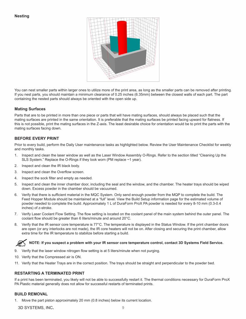
Nesting
You can nest smaller parts within larger ones to utilize more of the print area, as long as the smaller parts can be removed after printing . If you nest parts, you should maintain a minimum clearance of 0 .25 inches (6 .35mm) between the closest walls of each part . The part containing the nested parts should always be oriented with the open side up .
Mating SurfacesParts that are to be printed in more than one piece or parts that will have mating surfaces, should always be placed such that the mating surfaces are printed in the same orientation. It is preferable that the mating surfaces be printed facing upward for flatness. If this is not possible, print the mating surfaces in the Z-axis. The least desirable choice for orientation would be to print the parts with the mating surfaces facing down .
BEFORE EVERY PRINT Prior to every build, perform the Daily User maintenance tasks as highlighted below . Review the User Maintenance Checklist for weekly and monthly tasks .
1 . Inspect and clean the laser window as well as the Laser Window Assembly O-Rings . Refer to the section titled “Cleaning Up the SLS System .” Replace the O-Rings if they look worn (PM replace ~1 year) .
2 . Inspect and clean the IR black body .
3 . Inspect and clean the Overflow screen.
4 . Inspect the sock filter and empty as needed.
5 . Inspect and clean the inner chamber door, including the seal and the window, and the chamber . The heater trays should be wiped down . Excess powder in the chamber should be vacuumed .
6 . Verify that there is sufficient material in the MQC System. Only send enough powder from the MQP to complete the build. The Feed Hopper Module should be maintained at a “full” level . View the Build Setup information page for the estimated volume of powder needed to complete the build . Approximately 1 L of DuraForm ProX PA powder is needed for every 8-10 mm (0 .3-0 .4 inches) of z-stroke .
7 . Verify Laser Coolant Flow Setting. The flow setting is located on the coolant panel of the main system behind the outer panel. The coolant flow should be greater than 6 liters/minute and around 20°C.
8 . Verify that the IR sensor core temperature is 77°C . The temperature is displayed in the Status Window . If the print chamber doors are open (or any interlocks are not made), the IR core heaters will not be on . After closing and securing the print chamber, allow extra time for the IR temperature to stabilize before starting a build .
NOTE: If you suspect a problem with your IR sensor core temperature control, contact 3D Systems Field Service.
9 . Verify that the laser window nitrogen flow setting is at 5 liters/minute when not purging.
10 . Verify that the Compressed air is ON .
11 . Verify that the Heater Trays are in the correct position . The trays should be straight and perpendicular to the powder bed .
RESTARTING A TERMINATED PRINTIf a print has been terminated, you likely will not be able to successfully restart it . The thermal conditions necessary for DuraForm ProX PA Plastic material generally does not allow for successful restarts of terminated prints .
BUILD REMOVAL1 . Move the part piston approximately 20 mm (0 .8 inches) below its current location .

103D SYSTEMS, INC.
2 . Open the outer and inner chamber doors and raise the heater trays .
NOTE: The part bed surface should be allowed to cool to or below 85°C before opening the doors.
3 . Remove laser window baffle and replace with laser window insert plug. The plug helps from preventing airborne powder to get inside the laser window seating .
4 . Sweep loose powder from the liner plate onto the part bed . Pull the roller forward and brush powder from the roller bar onto the part bed . Return the roller to the left position .
5 . Place the extraction cylinder into the chamber and close and secure all doors . Ensure the extraction cylinder surrounds the print bed area . Move the piston to the start position .
6 . Once the piston is at the start position, open the doors and slide the extraction tray underneath the cylinder . Lock the tray into place . The extraction tray and cylinder can be moved to the MQC . Allow the print cake to continue cooling to 50°C before trying to break out parts . Use of the nitrogen cooling lid is optional .
SIFTING MATERIALTo operate the Material Quality Control (MQC) System, refer to the ProX 500 User Guide . 3D Systems suggests the following sifting techniques for DuraForm ProX PA Plastic material:
• Remove loose material from the print cake with a brush . Sift the loose material into the used bin of the MQC System, but discard the hard and chunky material from the final breakout and part cleaning.
• Sift the loose material from the print cake between each print .
NOTE: When collecting material from the print cake, use only the soft powder. Powder that is hard and cannot break down easily by hand should be discarded.
RECYCLING MATERIALTo operate the Material Quality Control (MQC) System, refer to the ProX 500 User Guide .
After a print, loose material can be sifted and reused in another print . Consistent recycling procedures are important in order to maintain consistent material properties . If recycling procedures are not followed, problems such as variable shrinkages and surface imperfections like “orange peel” may appear .
The DuraForm ProX PA Plastic material is a very fine blend of small particles. As you run prints, the material is exposed to heat and energy . As a result, the particles in the used powder tend to stick together forming larger particles . You can combat this trend with sifting and blending .
• Sifting removes undesirable particles from the used powder .
• Blending adds new particles of appropriate size .
• Blending also helps combat the changes in material melt viscosity of the used powder by creating a final blend with uniform materi-al melt viscosity that shows less variance from blend to blend .
BLENDING FRESH AND USED MATERIAL
NOTE: For a ProX 500 system, there is no overflow powder to use for a blend unlike the previous generation SLS systems. The overflow powder is recirculated back into the feed hopper during the print process and is ultimately consumed for the print process.
• The MQC System automatically initiates a blend cycle when it has enough material to blend a total of about 40 liters . For example, at a 50% fresh powder ratio, it requires about 20 liters in the fresh bin and about 20 liters in the used bin to initiate a new blend cycle .
• At any particular fresh powder ratio setting, the minimum volumes of fresh and used powder required to initiate a blend are dis-played on the MQC home screen .
• The recommended fresh powder ratio setting for DuraForm ProX PA material is 40% .
• The range for fresh powder ratio setting on the MQC System for DuraForm ProX PA material is 30% to 100% .
NOTE: A 30% fresh powder ratio setting for DuraForm ProX PA does not result in orange peel or deterioration of mechanical properties. However, parts that are prone to distortion tend to print better with a 40% fresh powder ratio setting .
CLEANING UP THE SLS SYSTEMMaterial may build up on the roller and in other areas in the print chamber, as well as on the MQC System . Refer to the procedures in the ProX 500 User Guide for the following cleaning information:
• Cleaning the SLS System Between Prints

113D SYSTEMS, INC.
• Cleaning the Laser Window
• Cleaning the Blackbody section
• Cleaning the Overflow Screen
• Cleaning the Sock Filter

123D SYSTEMS, INC.
3 POST-PROCESSING
This chapter covers various techniques for improving part surface finish after breakout and only highlights a limited number of basic post-processing techniques . Many companies develop their own techniques based on their unique needs .
This chapter includes the following topics:
• Tools and Cleaning Media
• Cleaning Procedures
• Repairing and Joining Parts
• Power Sanding
• Wet Sanding Procedure
• Sealing and Infiltrating Parts
• Sealing with a Water-Based Polyurethane
• Sealing with Imprex Superseal
TOOLS AND CLEANING MEDIAThe following is a typical list of tools and cleaning materials that you can use for post-processing:
• Hand-held files
• Round sanding tools
• Flat sanding tools
• Sandpaper (approximately 150 grit)
• Glass media blaster with a recommended bead size of 70 to 140 µm
• Cleaning cloth
• Pin vise with small drill bits
• Mini belt sander with 120 grit sandpaper belts
CLEANING PROCEDURESBefore performing any other post-processing technique, thoroughly clean the parts . To clean a DuraForm ProX PA Plastic part:
1 . Remove the print cake from the print chamber .
Caution: 3D Systems recommends allowing the print cake to cool to room temperature before removing parts from it .
2 . Brush away all loose material to expose the part .
3 . Use appropriate hand tools to remove all remaining material in corners and holes . Use a drill bit to clear holes .
NOTE: Do not recycle or blend this powder. It should be discarded.
4 . Using a glass bead media blaster at 4 .8 bar (70 psi), hold the part approximately 127 mm (5 inches) from the nozzle and blast it .
NOTE: Holding the nozzle too close to the part can cause “burning” (surface discoloration and degradation).
For a better surface finish, continue with the “Wet Sanding Procedure”.
REPAIRING AND JOINING PARTS3D Systems recommends cyanoacrylate (super) glues for repairing or joining parts made with DuraForm ProX PA Plastic materials . Use an accelerator with the cyanoacrylate . As an alternative, you can use a thin epoxy (such as a 5-minute epoxy) .
POWER SANDINGYou can use a mini-belt sander (with 5/16-inch belt, 120 grit, medium speed) to remove layering on the side walls of parts printed with DuraForm ProX PA Plastic materials .
WET SANDING PROCEDURETools and Equipment Required

133D SYSTEMS, INC.
• Sand paper (220 to 1200 grit)
• Running water
• Cloth or paper towel for drying part
Complete the following steps to wet sand a part:
1 . Dip the clean part in water .
2 . Sand the surface until you achieve the desired finish. Start with 220 grit followed by 320 grit, 400 grit, 600 grit, and 1200 grit.
NOTE: After using 320 grit, be sure to change the water frequently.
SEALING AND INFILTRATING PARTSParts printed with DuraForm ProX PA Plastic materials can be sealed or infiltrated with a variety of products, including primers, paints, polyurethanes, cyanoacrylates (i .e . “super glues”), and epoxies .
The parts tend to be dense, so low viscosity products or products that can be thinned are easier to use and would be advantageous to use to avoid altering a part’s dimensions .
For full infiltration, 3D Systems recommends that you use a vacuum chamber to infiltrate parts. If you only need a surface coat of sealant, then brushing or dipping is sufficient.
Caution: When working with infiltrants, use solvent-resistant gloves in a well-ventilated area.
Some suggested products:• Thermal-Cure Sealants: Godfrey & Wing Inc. 220 Campus Drive, Aurora, OH 44202
Phone: +1 .330 .562 .1440
Toll free: +1 .800 .241 .2579 Fax: +1 .330 .562 .1510
http://www .godfreywing .com/vacuum-impregnation/sealants/types-of-gw-sealants
Part Number: 95-1000A + catalyst
• UCAR Vehicle 443 Acrylic Emulsion: A Union Carbide product .
Mix 72% emulsion with 28% water to create a 32% solid mixture . Dip the parts in this mixture for a surface coat . Use an industrial oven at 70° C to dry parts afterwards .
• Cyanoacrylates: 3D Systems recommends Loctite 408 . For cyanoacrylates, use of an industrial oven or vacuum chamber is not recommended .
See also “Repairing and Joining Parts” .
SEALING WITH A WATER-BASED POLYURETHANEYou can use any water-based polyurethane sealant to infiltrate and seal parts printed with DuraForm ProX PA Plastic materials.
Tools and Equipment Required:• Metal pans deep enough to submerge parts
• Foam brush or applicator (optional)
• Industrial oven (optional)
• Vacuum Chamber (optional)
Procedure1 . Sand the part before sealing, if desired . See “Wet Sanding Procedure .”
2 . Coat and infiltrate the part with sealant using one of the following methods:
• Paint the sealant on with a foam brush .
• Immerse the parts in a container of sealant for five minutes. If the parts float, weigh them down or hold them down.
• To fully infiltrate thick-walled parts (i.e. parts with walls more than 7.5 mm [0.3 inches] thick), place them in a container of sealant in a vacuum chamber until air stops bubbling out of the sealant .
3 . Remove the part from the sealant and shake off the excess .

143D SYSTEMS, INC.
4 . Use compressed air to blow excess sealant off of inside features and out of cavities .
5 . Air dry the part for 4 to 24 hours, depending on part density and size . You can speed drying by using an oven at low heat (50°C) .
SEALING WITH THERMAL-CURE SEALANTS
Tools and Equipment Required:• Foam brush or applicator
• Thermal Cure sealant
• Convection Oven capable of at least 100 °C
• Vacuum Chamber (optional)
Procedure1 . Place the clean part on a tray to catch excess sealant .
2 . Apply the sealant to one side of the part using the foam brush . Be sure the entire side is coated .
3 . After the part face is coated, let the sealant sit on the part for 5 to 10 minutes to saturate the part surface .
4 . Turn the part over and apply sealant to the back side of the part .
5 . Set the oven to 100°C . Remove any excess sealant and place the part in the oven for 1 to 1 .5 hours or longer for parts with thick cross-sections .
6 . Remove the part and apply a second coat of sealant, repeating steps 2 through 5 .

153D SYSTEMS, INC.
4 PROPERTIES AND HANDLING
This chapter contains general information about DuraForm ProX PA Plastic, its properties and how it should be handled . It includes the following topics:
• Safety Data Sheets
• Material Handling
• Material Storage and Disposal
SAFETY DATA SHEET3D Systems provides safety data sheets (SDSs) with safety and handling information for the DuraForm ProX PA Plastic material . The document control number (DCN) for DuraForm ProX PA Plastic SDS is:
• DuraForm ProX PA Plastic: DCN 24168-S12-00-A
MATERIAL HANDLINGFor complete information, refer to the Safety Data Sheet (SDS) for DuraForm ProX PA Plastic .
Observe the following:• Avoid spilling material on the floor, and clean it up promptly if you do. Spilled material can cause floors to be very slippery.
NOTE: The operator must use an approved vacuum cleaner to clean up excess material. 3D Systems recommends an ESD or explosion-proof model. Contact 3D Systems Customer Service for purchasing options.
• After vacuuming spilled material, use a wet mop to clean the floor. The powder is difficult to sweep up.
• Due to the small particle size of DuraForm ProX PA Plastic material, it is likely to become airborne during handling .
For conditions where exposure to dust is likely, 3D Systems recommends a NIOSH-approved dust respirator for dust appropriate to the airborne concentration . Such conditions might include handling of material at the SLS system or the Material Quality Control (MQC) System .
MATERIAL STORAGE AND DISPOSALThis section contains storage information for DuraForm ProX PA Plastic, as well as disposal instructions .
General Storage InformationFor information regarding the MQC System, refer to the ProX 500 User Guide .
To avoid contamination, spilling, dust clouds, or mixing different types of materials:
• Store used material in properly labeled bottles . Be aware that they are subject to contamination, unless you seal them in some manner .
• Do not mix one type of material with another .
• Thoroughly clean the MQC System when changing materials .
• Thoroughly clean the SLS system machine when changing materials .
Storing DuraForm ProX PAIf the material becomes contaminated, its processing characteristics may change . This can produce undesirable results in part quality . The following storage guidelines suggest ways to minimize contamination and keep powder under optimum conditions:
• Store at a temperature of 40° C or less .
• Seal the container .
Material DisposalWhen disposing of DuraForm ProX PA, follow any local ordinances and the guidelines in the Safety Data Sheet (SDS) .

163D SYSTEMS, INC.
5 SOLVING PROBLEMS
This chapter is organized alphabetically by issue name . It contains the following topics:
• Introduction to Problem Solving
• Bonus Z
• Clumping
• Cracking of Print Bed
• Crystals and Condensation
• Curling, During Print
• Curling, Post-Print
• Glazing, During Print
• Growth
• Melting, Print Bed
• Missed Scan
• Orange Peel
• Short Feeds
• Stray Vectors
• Wash Out
• Weak Parts/Porosity
INTRODUCTION TO PROBLEM SOLVINGWhile optimizing profile parameters can eliminate many problems, it is often useful to monitor a print so you can continually establish these parameters .
Reasons to observe a print:• Some parts may require attention and adjustment during the print .
• Your profiling will become more accurate through observation. As your profiling becomes more accurate, the need for future obser-vation will become less frequent .
Problem Description FormatYou will find the following information about each issue:
• Description: Explains the problem and provides a visual representation of it . The description includes such things as where and when the problem might occur .
• Theory of Cause: Contains a brief explanation of what might have caused the problem .
• Visual Signs: Describes any observable information that may not be covered in the Description section .
• Consequences: Details what can happen to print quality if you do not correct the problem .
• Corrective Action: Describes what you can do to avoid or recover from the problem .
• Related Problems: Indicates whether this problem might interact with or be related to another problem .
BONUS Z Description: Bonus Z occurs when the laser melts a part beyond the specified depth—usually 0.1 mm (0.004 inches) on the first few scans—and causes vertical growth in the Z axis. The difference between growth and bonus Z is that growth may occur on any part edge, while bonus Z occurs only on downward facing surfaces.

173D SYSTEMS, INC.
Theory of Cause: When the first layer is scanned, the laser penetrates to the unmelted material below the print boundary. In extreme cases, bonus Z will occur with wash out.
Visual Signs: You cannot observe this during printing .
Consequences: The part is out of tolerance in the Z axis.
Corrective Action: While printing, there are no corrective actions you can take .
Prior to beginning the print job, you can:
• Minimize the possibility of bonus Z by reducing the Fill Laser Power parameter in the Print Profile for the first few layers (between the first and fourth layers).
• Use the Z-growth compensation features of Build Setup; see your Build Setup help.
If bonus Z occurs, you can clean the part during post-processing by sanding or machining off the appropriate amount.
Related Problems: “Wash Out”
CLUMPINGDescription: Agglomerated material on the material bed surface accumulates in front of the roller as it moves across the print bed and streaks appear behind the roller .
Theory of Cause: This is usually the result of one of the following:
• Improperly sifted, recycled material .
• Overheating the material in the feed hopper .
• Contaminants in the compressed air or air line .
Visual Signs: The roller pushes clumps across the print bed which may cause streaks to appear after the roller passes .
Consequences: Material does not feed properly, causing poor quality parts . Improper material feeding causes uneven material thickness which may cause growth or inadequate melting . Streaks may be apparent on upward and downward facing surfaces of parts .
Corrective Action: Reduce the temperature setpoints for the feed hopper .
Thoroughly sift recycled material before using it . See “Recycling Material” on page 10 and “Sifting Material” on page 10 .
Make sure your material storage methods do not allow contaminants into the material . The section “Material Storage and Disposal” describes appropriate material storage .
Make sure the supply for clean dry air meets the specifications given in your printer’s Facility Guide.
If clumping occurs in an area of the print bed that does not contain the part(s), you probably can continue the print job .
If clumping occurs in the area of the print bed containing the part(s), you may not be able to complete the print job successfully .
Side view of roller and powder, showing clumps

183D SYSTEMS, INC.
If you terminate the print, do the following:
1 . Discard any lumps of material .
2 . Clean the print chamber .
3 . Clean the overflow screen.
4 . Clean the roller .
Related Problems: “Cracking of Print Bed”
CRACKING OF PRINT BEDDescription: The surface of the print bed cracks open as the roller moves across it .
Theory of Cause: Excessive heating rate or temperature from the heaters causes partial melting of material on the print bed surface(s) .
Short feeds caused by uneven powder feeds .
Mechanical problems with the roller can also cause cracking of the print bed . If you suspect mechanical problems, contact 3D Systems .
Visual Signs: Cracks appear on the surface of the bed .
Consequences: If the part is printed in the area that is cracking, the part will crack too .
Corrective Action: Decrease the Print Heater PID Setpoint in 2 °C increments until the crack disappears .
If cracking occurs during the Warm-up stage, you may have ramped up the temperature too quickly. Do not ramp to the final set point until real time calibration starts, (6mm into the warm-up stage) .
CRYSTALS AND CONDENSATIONDescription: During a print, a thin layer of needle-like crystals and/or a film of condensation forms on cool surfaces in the print chamber. The N flow across the IR sensor and the laser window will keep the IR sensor and laser window clean, although the user should inspect them before every build .
NOTE: A slight amount of condensation will probably form on the laser window every print. If the condensation is extremely heavy across the entire window, call 3D Systems Customer Service; this may indicate a problem with the SLS system .
Process Chamber Floor
Part Bed

193D SYSTEMS, INC.
CURLING, DURING PRINTDescription: Edges or corners of the print rise above the print bed surface .
Theory of Cause: During the print, temperature differences in different regions of the print cause uneven shrinkage, which, in turn, causes curling . This usually occurs when the print temperature dips too low after the material is added . Curl during printing can also occur if the print bed temperature is too low .
Visual Signs: The edges of the print rise above the print bed surface after a layer is scanned . Curling usually occurs immediately after a layer of material is added, but a delay sometimes occurs between the addition of the material layer and the observation of curling .
Consequences: Parts (especially those with large surface cross-sections) are not flat.
If curling is severe, the print may shift in the print bed when the roller passes it .
Corrective Action: For minor curling, changes during the print may help . This includes adjusting the Part Bed Set point or the Heater Ratios .
Once moderate to severe curling has occurred, the part will continue to appear curled even after adjustments have been made .
Increasing the laser power significantly will help a part to stop curling, but this will also cause growth on the part.
If severe curling occurs, you may want to terminate the print and begin a new one . Consider the following changes to prevent the problem in future prints:
• Make sure the system has gone through a full Warm-up stage .
• Check the feed hopper Set Points and the Print Heater Set Point .
• Excess feed material may contribute to curling during printing as some of the feed material may not be hot enough, especially with short layer times .
• Make sure Cylinder Heater Enable is set to 1 and the Cylinder Heater Set Point is set correctly .
NOTE: Adjust parameters in small increments to avoid introducing problems caused by too much heat. If temperatures are raised too greatly and too quickly, the material can start caking.
6 .35 mm .25 in .
6 .35 mm .25 in .
6 .35 mm .25 in .
6 .35 mm .25 in .
5 .08 mm .20 in .
5 .08 mm .20 in .
Curling and Z-Inaccuracy

203D SYSTEMS, INC.
CURLING, POST-PRINTDescription: The final part is not flat and is showing curling similar to that experienced with injection-molded parts.
Theory of Cause: When the part is buried during the Print stage, excessive cooling rates and thermal gradients produce unbalanced stresses in it. Excessive cooling rates usually occur on parts printed first in a print job (the parts at the lowest Z levels). You may also have removed the print from the print chamber prematurely .
Visual Signs: The final part is not flat. You cannot observe this until the part is broken out.
Consequences: Curled parts (especially those with large surface cross-sections) are not flat, but the Z dimensions are correct.
Corrective Actions: You can attempt to repair curled parts, and you can change your prints to prevent future runs from curling .
Repairing Curled Parts: Curling can sometimes be reduced or removed:
1 . Clamp the part to a flat plate.
2 . Place the part in an oven for one hour at 80 C .
3 . Remove the part from the oven and allow to cool for 2 to 4 hours (overnight is preferred) before removing clamps .
Preventing Curl in PrintsYou may want to take one or more of the following actions to prevent parts from curling:
Your first recourse should be to use the Superheat technique.
Refer to the section titled “Superheat”. If this does not fix the problem, try the following steps:
• Add a Heat Barrier: If you are not already using a heat barrier, add a thin layer of throwaway parts below the parts you wish to print .
• Increase Print Bed Setpoint: Increase the Print Bed PID Setpoint by 1 or 2°C . Increasing the Print Bed PID Set point too greatly may cause a more difficult breakout and reduce the amount of material that can be recycled.
• Change Part Orientation: Rotate the part 15° around the Y and Z-axis; this reduces cooling stresses.
6 .35 mm .25 in .
6 .35 mm .25 in .
6 .35 mm .25 in .
Curling and Associated Z-Shrinkage
6 .35 mm .25 in .
6 .35 mm .25 in .
6 .35 mm .25 in .

213D SYSTEMS, INC.
• Print in Layers: Print parts at the third or fourth layer of parts in the print cake . For information on setting up a print in layers, see “Setting Up a Print .”
• Allow Time to Cool: Allow the print cake to cool longer inside the SLS system (e .g . one hour longer for every hour the build took to complete) and allow the print cake to cool outside the SLS system completely before removing the parts .
GLAZING, DURING PRINTDescription: Small local regions of material melt on the print bed and cause the bed to glisten . This occurs during the print and should be distinguished from the glazing point . The melting point of DuraForm ProX PA Plastic occurs at approximately 1 to 2°C above the glazing point .
Theory of Cause:• The IR sensor is not calibrated correctly or is not clean .
• Uncorrected short feeding .
• The Part Heater Setpoint in the Print Profile is too high.
• The system is trying to reach the temperature set point too quickly .
Visual Signs: All or part of the print bed begins to glaze . In extreme cases, the material melts completely .
Consequences: Glazing can affect the uniformity of a layer of material. Parts can be difficult to remove from the print cake during rough breakout . The cake can also shift in the print bed . In severe cases, the print cake may melt and become a solid block .
Corrective Action: If this condition is uncorrected and glazing becomes severe melting, you may not be able to continue the print . You can try to reduce the print bed temperature until the print bed stops melting . If severe melting occurs, terminate the print and remove the melted powder plug since it will affect the print set points through the next several inches .
There are several actions you can take to prevent glazing:
• In the Print Parameters Profile, reduce the Part Heater set point.
• In the Warm-up stage of the Print Profile, ramping the heater set points.
• Use Offline Calibration to make sure IR sensor is calibrated. See “Offline IR Calibration” on page 7.
If you have performed all the preceding actions and melting still occurs, you may need to call certified service personnel to calibrate
the IR sensor .
Related Problems: “Crystals and Condensation”, “Melting, Print Bed,” “Cracking of Print Bed”
GROWTHDescription: Growth occurs as material sinters on the part, slurring features and altering part dimensions .
Growth is particularly apparent with small features or small holes. The difference between growth and Bonus Z is that growth may occur on any part edge while Bonus Z occurs only on downward-facing surfaces.
Theory of Cause: The laser power may be excessive for thick cross- sections, or the print bed temperature may be too high .
Visual Signs: Growth may not be apparent during the print .
Consequences: If the part has detailed features, the features may blur. Parts may be oversized. Parts may be difficult or even
Normal
Growth

223D SYSTEMS, INC.
impossible to break out .
Corrective Action: Reduce the Part Heater PID Setpoint parameter . Reduce the Fill Laser Power parameter .
Related Problems: “Wash Out”
MELTING, PRINT BEDDescription: The material in the print bed melts and solidifies.
Theory of Cause: Possible causes include:
• IR sensor not calibrated correctly or dirty
• Part Heater set point too high
• Short feeds
• System trying to reach the temperature setpoint too quickly
Visual Signs: Melting first occurs in small patches in the hottest areas of the print bed. Observing which areas melt first indicates the hottest spots in your print bed .
Consequences: Melting occurs after glazing . The print bed temperature increases . Melting is a far more serious condition than glazing .
Corrective Action: Terminate the build . There are several actions you can take to prevent melting:
• In the Print Parameters Profile, reduce the Part Heater set point and/or use ramping for the heater set points.
• Make sure IR sensor block temperature is correct and that the core heater is working .
• Perform an Offline IR sensor calibration. See “Offline IR Calibration” on page 7.
• Refer to the section titled “Cleaning Up the SLS System” .
If none of the above actions prevents melting, call certified service personnel to calibrate the IR sensor and/or adjust the thermocouples .
Related Problems: “Cracking of Print Bed”, “Crystals and Condensation”, and “Glazing, During Print” .
MISSED SCANDescription: The laser does not completely scan the fill area in a part.
Melting
Normal Layer
Missed Scan
Area scanned by laser

233D SYSTEMS, INC.
Theory of Cause: The STL file is incorrect. This problem is not material related.
Visual Signs: You can observe that the scanned area is incorrect .
Consequences: The part geometry is incorrect, and the part may have poor properties .
Corrective Action: Depending on the severity of the problem, you may need to terminate the print and start over . If the missed scan occurs only on one layer or slice, you may be able to complete the print .
If you experience missed scans, make it a practice to verify that the STL file is not missing facets and that the normals are correct prior to beginning a print by using the Preview application. If the STL file is incorrect, you next need to verify that the original CAD file is correct .
If the original CAD file is correct, the STL file could be corrupt. Generate a new one and preview the print again. If the problem recurs, contact 3D Systems customer support .
If the original CAD file is incorrect, make the necessary changes to the CAD file and save the file in STL format. With the new file, set up a build packet and print the part again .
Related Problems: “Stray Vectors”
ORANGE PEELDescription: Vertical surfaces on the part have voids or recesses that create a distinctive orange-like texture . This problem usually appears on surfaces printed parallel to the front of the system .
Theory of Cause: Lack of density at the part’s surface caused by excessive reuse of the material or thermal problems in the print chamber .
Visual Signs: None .
Consequences: Although other part properties remain unchanged, surface finish and appearance are affected.
Corrective Action: Take one of the following actions:
• Verify that you are following correct sifting and recycling procedures and correct any problems . Refer to the sections titled “Sifting Material” and “Recycling Material .”
• Use a higher ratio of fresh powder to used powder .
• Increase the post- and/or pre-add powder delays
• In the Part Profile, increase the laser power.
• In the Print Profile, increase Part Heater setpoint.
Related Problems: “Weak Parts/Porosity”
SHORT FEEDSDescription: The roller does not deliver enough material to cover the previous layer .
Theory of Cause: Short feeds can occur when the feed amount is too short; the part cross-section changes from small to large.
Visual Signs: Part bed not completely covered after a layer is spread . Part bed cracking may also appear .
Consequences: The part will usually be weak, may delaminate at layers where short feeds occurred, and may have surface imperfections .
Corrective Action: Increase the Feed Amount parameters in the Print Parameters Profile or use the Prime Cycle button.
Top View of Part Bed
243D SYSTEMS, INC.
Caution: Exercise care when varying the Feed Amount parameters. The feed material during a print is considerably cooler than the material in the print bed. Using a feed that is too large can cause excessive cooling of the part as the material is delivered, which will lead to curl during printing.
You also may want to use the Prime Cycle button to cover the part .
Related Problems: “Melting, Print Bed”, “Weak Parts/Porosity”, and “Cracking of Print Bed”
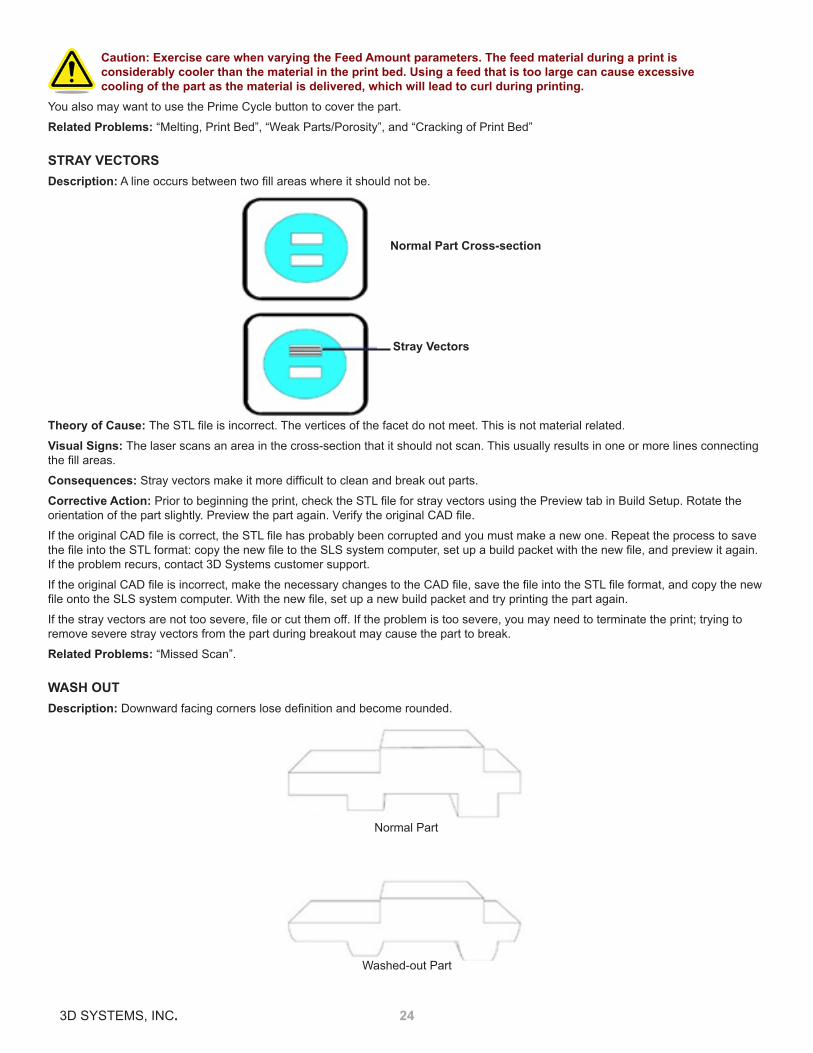
STRAY VECTORSDescription: A line occurs between two fill areas where it should not be.
Theory of Cause: The STL file is incorrect. The vertices of the facet do not meet. This is not material related.
Visual Signs: The laser scans an area in the cross-section that it should not scan . This usually results in one or more lines connecting the fill areas.
Consequences: Stray vectors make it more difficult to clean and break out parts.
Corrective Action: Prior to beginning the print, check the STL file for stray vectors using the Preview tab in Build Setup. Rotate the orientation of the part slightly. Preview the part again. Verify the original CAD file.
If the original CAD file is correct, the STL file has probably been corrupted and you must make a new one. Repeat the process to save the file into the STL format: copy the new file to the SLS system computer, set up a build packet with the new file, and preview it again. If the problem recurs, contact 3D Systems customer support .
If the original CAD file is incorrect, make the necessary changes to the CAD file, save the file into the STL file format, and copy the new file onto the SLS system computer. With the new file, set up a new build packet and try printing the part again.
If the stray vectors are not too severe, file or cut them off. If the problem is too severe, you may need to terminate the print; trying to remove severe stray vectors from the part during breakout may cause the part to break .
Related Problems: “Missed Scan” .
WASH OUTDescription: Downward facing corners lose definition and become rounded.
Normal Part Cross-section
Stray Vectors
Normal Part
Washed-out Part

253D SYSTEMS, INC.
Theory of Cause: As a melted part cools, heat is transferred to the surrounding material, causing the material to bond to the part surfaces (growth). Part corner regions cool faster than flat regions, so corners exhibit less growth than surfaces, which causes the appearance of rounded corners .
Visual Signs: You can observe wash out when small slots fill in with melted material. Otherwise, wash out is observed on parts after breakout .
Consequences: The part features become rounded, mostly on the downward-facing surfaces . Wash out may be followed by growth . If you correct part wash out early enough, you can continue the print with little observable growth; however, you can still observe wash out in the finished part.
Corrective Action: Reduce the Fill Laser Power parameter. Periodically, you may want to run a set of parts with fine features at different laser powers to optimize the Fill Laser Power parameter .
Related Problems: “Bonus Z”, “Growth”, and “Melting, Print Bed.”
WEAK PARTS/POROSITYDescription: Parts appear porous and opaque rather than translucent . The parts are brittle .
Theory of Cause: The laser window has been covered with heavy condensation, or the laser power is not high enough . When DuraForm ProX PA Plastic is recycled, more laser power can be required to achieve full density .
Visual Signs: There is little observable contrast between melted and non-melted areas in the print bed .
Consequences: The part will have low strength and density . Curl during printing may occur . Parts printed with DuraForm ProX PA Plastic material can tolerate some porosity if you want extremely crisp, sharp details and edges . Porous parts’ mechanical properties, such as failure strain and tensile strength, are approximately one-third to one-half the corresponding qualities of fully dense parts .
Corrective Action: To minimize the problem, you can:
• Clean the laser window . See “Cleaning the Laser Window” on page 10 .
• Increase the Fill Laser Power parameter during the build .
• Increase the Print Bed Temperature PID Setpoint parameter .
• Discard the old material and replace it with unused material .
If these actions do not improve part density, call service personnel to check the laser and laser focus .
Related Problems: “Crystals and Condensation .”

3D Systems, Inc .
333 Three D Systems Circle | Rock Hill, SC 29730 | USA
www .3dsystems .com
©2016 3D Systems, Inc . All rights reserved .
PN: 134015-00 Rev . C