Durability of Concrete Beams Prestressed with CFRP … · Durability of Concrete Beams Prestressed...
21
1 Durability of Concrete Beams Prestressed with CFRP Halit Cenan Mertol, Sami Rizkalla, Paul Scott, Janet M. Lees and Raafat El-Hacha Synopsis: The need for sustainable structures is the driving force for the growing international interest in using advanced materials such as fiber reinforced polymer (FRP) materials for civil infrastructure applications. To date, FRP materials have not realized their full potential within the construction industry. One of the contributing factors is the limited information regarding their long-term performance. In particular, since the service life of a civil engineering structure is typically 50 to 100 years, knowledge of the long- term durability of FRPs is of prime importance. The research work presented in this paper is the result of a research collaboration between North Carolina State University and the University of Cambridge. The research investigates the durability of concrete beams prestressed with CFRP bars and compares the results with those of companion beams prestressed with steel wires. A total of 15 beams have been constructed and tested under different mechanical and environmental conditions. The parameters included in the program were the level of sustained stress in the bars and wires (55 and 70 percent of the ultimate bar or wire strength), the environmental exposure condition (air exposure and continuous exposure to 15 percent by mass salt water spray at 54 °C temperature), the length of time under sustained load (9 and 18 months) and the method of testing (with or without application of cyclical loading prior to static testing to failure). The experimental program illustrates that CFRP prestressed concrete beams exhibit comparable ultimate strength and fatigue strength properties in comparison to equivalent steel prestressed concrete beams. Furthermore, test results show that the beams prestressed with steel wires did not survive the environmental exposure over 12 months whereas the beams prestressed with CFRP bars survived up to the end of the 18 month long extreme environmental exposure, indicating the excellent durability of CFRP in the marine environment. Provided that provision is made for the lack of CFRP ductility in comparison to steel, the research undertaken has indicated that CFRP prestressed concrete is a durable, appropriate option when designing structures for use in offshore environments. Keywords: Durability; prestressed concrete; beam; carbon fiber reinforced polymer bars; steel wires; cyclic loading; environmental exposure; marine environment
Transcript of Durability of Concrete Beams Prestressed with CFRP … · Durability of Concrete Beams Prestressed...

1
Durability of Concrete Beams Prestressed with CFRP
Halit Cenan Mertol, Sami Rizkalla, Paul Scott, Janet M. Lees and Raafat El-Hacha Synopsis: The need for sustainable structures is the driving force for the growing international interest in using advanced materials such as fiber reinforced polymer (FRP) materials for civil infrastructure applications. To date, FRP materials have not realized their full potential within the construction industry. One of the contributing factors is the limited information regarding their long-term performance. In particular, since the service life of a civil engineering structure is typically 50 to 100 years, knowledge of the long-term durability of FRPs is of prime importance. The research work presented in this paper is the result of a research collaboration between North Carolina State University and the University of Cambridge. The research investigates the durability of concrete beams prestressed with CFRP bars and compares the results with those of companion beams prestressed with steel wires. A total of 15 beams have been constructed and tested under different mechanical and environmental conditions. The parameters included in the program were the level of sustained stress in the bars and wires (55 and 70 percent of the ultimate bar or wire strength), the environmental exposure condition (air exposure and continuous exposure to 15 percent by mass salt water spray at 54 °C temperature), the length of time under sustained load (9 and 18 months) and the method of testing (with or without application of cyclical loading prior to static testing to failure). The experimental program illustrates that CFRP prestressed concrete beams exhibit comparable ultimate strength and fatigue strength properties in comparison to equivalent steel prestressed concrete beams. Furthermore, test results show that the beams prestressed with steel wires did not survive the environmental exposure over 12 months whereas the beams prestressed with CFRP bars survived up to the end of the 18 month long extreme environmental exposure, indicating the excellent durability of CFRP in the marine environment. Provided that provision is made for the lack of CFRP ductility in comparison to steel, the research undertaken has indicated that CFRP prestressed concrete is a durable, appropriate option when designing structures for use in offshore environments. Keywords: Durability; prestressed concrete; beam; carbon fiber reinforced polymer bars; steel wires; cyclic loading; environmental exposure; marine environment

2
Halit Cenan Mertol is a member of ACI. He obtained his B. Sc. (1999) and M. Sc. (2002) from Middle East Technical University in Turkey. He is currently a Ph. D. candidate in Civil, Construction and Environmental Engineering in North Carolina State University, Raleigh, North Carolina. His main interests are fiber reinforced polymer materials and high-strength concrete. Sami Rizkalla is a Distinguished Professor of Civil and Construction Engineering in the Department of Civil, Construction and Environmental Engineering, North Carolina State University. He is the Director of the Constructed Facilities Laboratory and NSF I/UCRC in Repair of Structures and Bridges at North Carolina State University. He is a fellow of ACI, ASCE, CSCE, EIC and IIFC. Paul Scott is a member of the Institute of Structural Engineers and the Institute of Mechanical Engineers, having obtained a Masters degree in Mechanical Engineering from the University of Nottingham in 2004. He is currently a Ph. D. candidate in the Structures group at the University of Cambridge, UK, investigating aspects of CFRP prestressed concrete durability in the marine environment. Janet M. Lees is a University Senior Lecturer in the Department of Engineering at the University of Cambridge. Her research interests include FRP prestressed concrete, the strengthening and repair of existing structures, GFRP pipelines and recycled materials in concrete. Raafat El-Hacha, MACI, is an Assistant Professor in the Department of Civil Engineering at the University of Calgary, Canada. He is a member of ACI Committee 440 "Fiber Reinforced Polymer (FRP) Reinforcement" and co-chair of Sub-Committee 440-I "FRP Prestressed Concrete". He is an associate member of joint ACI-ASCE 423 "Prestressed Concrete" and ACI 408 "Bond and Development of Reinforcement". His research interests include strengthening concrete and steel structures and reinforcing and prestressing concrete structures with FRP, blast mitigation and repair using FRP.
INTRODUCTION The need for sustainable structures is the driving force for the growing international interest in the use of fiber reinforced polymer (FRP) materials for civil infrastructure applications. To date, FRPs have not realized their full potential within the construction industry. One of the contributing factors is limited information regarding their long-term performance. In particular, since the service life of a civil engineering structure is typically 50 to 100 years, knowledge of the long-term durability of FRPs is of prime importance. The durability of FRP materials depends on numerous factors including the fiber properties, resin properties and manufacturing process used. In general, the durability of CFRP has been found to be very good since carbon is considered one of the most durable types of fibers when compared to glass or aramid alternatives. However, the majority of

3
the research reported on FRP durability considers either a particular mechanical loading regime or a particular environmental exposure condition in isolation. Whilst valuable results can be obtained using such approaches (Balazs and Borosnyoi 2001, Micelli and Nanni 2004); in service, structures will be subjected to both mechanical and environmental loadings concurrently. It is therefore necessary to determine the consequences of any mechanical/environmental deterioration on the overall performance of a structure prestressed and/or reinforced with these materials. These effects must be investigated in order to build confidence within the industry and to identify both the limits and potential of FRPs in structural applications. This research work, performed at NCSU and conducted in collaboration with the UC, investigated the durability of concrete beams prestressed with CFRP bars. Although the results of the research will apply to many types of structure, the initial objective was to build on the preliminary work carried out at the UC on systems for CFRP prestressed concrete wind turbine masts (Agyei 2002). These masts combine high-strength concrete with high-strength CFRP bars to form a strong and durable structure. A prominent issue in the design of wind turbine masts is the fatigue loading in a corrosive environment. Initially, studies were carried out at the UC on the fatigue performance of high-strength concrete beams prestressed with CFRP bars (Agyei 2002) and the results were promising. However, the research did not incorporate the implications of severe environmental conditions such as salt water spray to which offshore structures would be subjected. The current project extended the work using the environmental chamber at NCSU. Within the chamber, durability tests were performed simultaneously as the specimens were subjected to sustained loading. Understanding the behavior of the CFRP material under these conditions is required in order to gain information on its corrosion fatigue performance as a prestressing reinforcement.
RESEARCH SIGNIFICANCE The research findings provide a unique evaluation of the durability and estimation of the service life of concrete structures prestressed with CFRP bars when compared with equivalent structures prestressed with steel wires. The experimental program investigated concrete beams prestressed with CFRP bars or steel wires which were subjected to sustained loading and environmental exposure prior to testing under realistic static and fatigue loading conditions. The information summarized in this paper provides a valuable contribution to the work of ACI Committee 440 which is currently in progress on the development of a comprehensive document on the durability of FRP for concrete structures.
EXPERIMENTAL PROGRAM The test series considered in the experimental program consisted of fifteen concrete beams prestressed with either CFRP bars or steel wires. The beams were precracked prior

4
to being subjected to various combinations of sustained loading and exposure conditions. The pre-cracking generated a path for moisture to propagate directly to the prestressing bars and wires, thus representing the most severe exposure conditions in the field. The precracked beams were subjected to two different sustained load levels that generated a stress level in the bars and wires of 55 or 70 percent of their ultimate tensile strength, fpu. Eight of the beams subjected to sustained load were placed into the environmental chamber to simulate harsh environmental effects whereas the rest of the specimens subjected to similar sustained loads were exposed to air for comparison purposes. The beams were subjected to a combined sustained load and environmental exposure for either 9 or 18 months. After the environmental exposure and sustained load program was completed, the beams were statically loaded to failure, in certain tests after having been subjected to cyclical loading. A summary of the testing scheme is given in Table 1. Test Specimens The beam design was based on the fatigue study completed by Agyei (2002) at the UC. The beams tested at NCSU had 108x203 mm rectangular cross-section with an overall length of 2130 mm as shown in Figure 1. Each beam contained two prestressing bars or wires with a spacing of 64 mm and a clear cover of approximately 20 mm from the side of the beam. The distance from the bottom surface of the beam to the center of the bar or wire was 32 mm. Material Properties In all the test specimens, a special type of cement, SPC cement, produced by Holcim, Inc. and a single type of aggregate, Lillington sand, were used to obtain a high-strength concrete. The mixture included dry densified silica fume to increase the strength and a HRWRA to improve the workability of the mixture and enable the use of a low water/cementitious material ratio. Polypropylene fibers were also used to improve the resistance of the concrete to shrinkage and cracking. Details of the concrete mixture design are given in Table 2. All the materials were mixed in a 0.06 m3 capacity drum mixer. The moisture content of the sand was measured and the total amount of water in the mixture was adjusted accordingly. The sand, cement, silica fume and fibers were combined in the drum and mixed in a dry condition. The water was added followed by the HRWRA. All the ingredients were mixed for a few minutes in the mixer prior to casting. Further mixing was done by hand using trowels and shovels to ensure that there was no unmixed material at the corners of the pan. Due to the limited capacity of the drum mixer, multiple batches were mixed continuously to cast multiple test specimens. Ten 102x203 mm companion cylinders were cast for each test specimen to determine the compressive concrete strengths on the day of bar or wire detensioning, at the time the beam was precracked, at the commencement of the sustained loading, when the beam was tested to failure and the tensile strength at the time of precracking. The concrete cylinders were exposed to the same environmental conditions as their companion beams.

5
The CFRP bars, supplied by SACAC Ltd, consisted of Tenax UTS fibers in an epoxy matrix. The CFRP bar properties were independently confirmed by an ultimate bar strength measured from anchor tests and found to be consistent with the data supplied by the company. The steel wires were supplied by VSL. A single wire from a 1200 kN seven-wire 12.7 mm low relaxation prestressing steel strand was used. The diameter was comparable to that of the CFRP bar. The breaking stress of the single wire was assumed to have the typical 1940 MPa tensile strength. Though the standard deviations of the bar and wire tensile properties were not measured, the nominal values supplied by the manufacturers are given in Table 3. The initially applied prestressing level was 0.55 fpu for both the CFRP bars and steel wires. The test specimens prestressed with CFRP bars were designed to fail by bar rupture and the stresses in the concrete would be fairly low. The test specimens prestressed with steel wires were designed to fail by the yielding of the wire followed by concrete crushing. Specimen Preparation A prestressing rig was constructed using steel HSS steel members at the ends and built-up sections at the sides. A view of the prestressing rig is shown in Figure 2. The built-up sections consisted of 2 channel sections. Each end of the stressing rig consisted of two HSS steel sections separated using a 25.4 mm plate to form a slot through which the bars and wires could pass. The prestressing rig was bolted to the strong floor using threaded rods. The formwork was constructed so that four test specimens could be cast in the prestressing rig simultaneously. Two specimens were located side by side, with the other two specimens connected to the ends of the first two specimens. The formwork was constructed using 25.4 mm thick plywood to enable repeated usage. The ends of the formwork had holes through which the bars and wires could pass. The plywood at the ends was cut along the center of the holes to form two parts. The lower part of the end plywood was secured to the base plate prior to locating the bars and wires. The upper part of the end plywood was fixed after the bars and wires were tensioned. Two cross beams were used to fix the formwork to the strong floor to avoid movement of the formwork during casting and vibration. Expansive cement anchors were used to prestress the CFRP bars to avoid possible premature bar failure due to stress concentrations within the anchorage zone. An anchorage system using steel tubes and expansive cement was employed after successive pilot tests. The CFRP bars were inserted into 254 mm long steel tubes with an internal diameter of 19 mm and a thickness of 7.7 mm. In each case, the bar was centered in the tube which was subsequently filled with expansive cement mixed with 28.5 percent water by weight. An end cap was used to seal one end of the tube and a hole was drilled in the center of the cap to center the bar. Each anchor was cast vertically at the dead end of each bar. At the other end of the bar, the live end, a 355.6 mm long steel tube with an outside diameter of 21.34 mm was used. The inner tube surface was threaded over a length of 82.55 mm to fit a 15.88 mm threaded rod which was used for prestressing the bar. The unthreaded regions of the tube had an inside diameter of 13.21 mm. A central hole was drilled into the end of the threaded rod which was screwed into the threaded section of the tube so as to center the bar. After casting one anchor and waiting for one day, the

6
CFRP bar was inverted and the tube at the other end was filled with expansive cement. The loads cells were located between the anchors prior to casting the second anchor. The anchors were cured for three days. The tensile tests on the anchorage system showed that the CFRP bar failed in the anchor region at a load of 26 kN which was much greater than the design prestressing force of 15 kN. The live and dead ends of the CFRP bars are shown in Figure 3. For the stressing of the steel wires, 4 mm multiple use chucks and 4 mm reusable anchor chucks were used for the dead and live ends respectively. Initial tensile tests performed on an anchored short length of steel wire confirmed a breaking load of 25 kN. These results indicate that both the CFRP bars and the steel wires had roughly the same breaking loads. The live and dead ends of the steel wires are shown in Figure 4. Prior to stressing, the bars and wires were located in the desired positions and a small prestress was applied to position the bars and wires in their location. Each bar and wire was stressed using a hollow hydraulic jack with a central hole supported on a jacking chair as presented in Figures 3 and 4. When the desired prestressing force, 14.7 and 15.1 kN for the CFRP bar and steel wire respectively, was reached, the bar or wire force was transferred from the jack to the end plate. Each bar or wire was stressed sequentially. After all four bars or wires had been stressed, minor adjustments were made by tightening or loosening the bearing nuts to ensure the prestressing loads in all the bars and wires were as desired. Casting of the test beams took place within two hours of prestressing. Four batches were mixed in the drum mixer to cast four specimens, simultaneously. Due to concerns about inadvertently damaging the bars and wires, 25.4 mm vibrators were applied directly to the formwork rather than the concrete. After casting, the beam specimens and companion cylinders were covered with a polythene sheet to reduce evaporation. Furthermore, water was sprayed on the specimens twice a day to ensure proper hydration. The beams were typically detensioned three days after casting. By this time the average compressive strength of the concrete was approximately 46 MPa. The bars and wires were detensioned initially at the live end prior to cutting the bars and wires at the dead end using a hacksaw. The formwork was demolded and the beam specimens were stored outside the laboratory. Test Set-Up and Method All the beams were precracked under a two point simply supported loading condition as shown in Figure 5. The precracking was carried out between 28 and 30 days after casting in order to maintain a consistent concrete tensile strength in all the test beams. The test procedure consisted of two loading cycles to determine the uncracked and cracked stiffness of each beam specimen. For the first loading cycle, each beam specimen was loaded up to a level corresponding to a bar or wire stress level of approximately 70 to 75 percent of fpu and then unloaded. For the second loading cycle, the specimen was reloaded to the same load level and unloaded again.

7
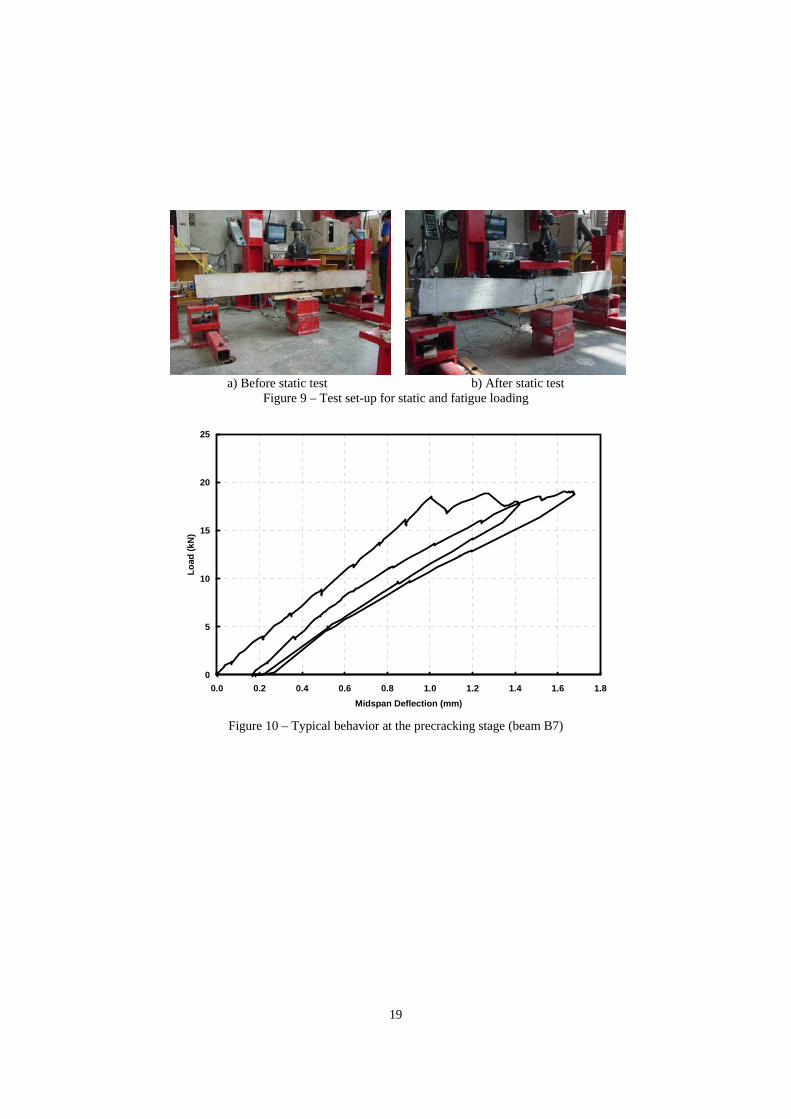
The sustained loading was applied to the precracked beams using a two point simply supported loading configuration. Threaded rods were used to load the beams against a supporting slab as shown in Figure 6. Springs were used to compensate for any load loss due to creep. The specimens were loaded so that the stress levels in the bars or wires were 55 percent or 70 percent of fpu. Seven specimens under sustained load were exposed to air as control specimens as shown in Figure 7. Eight beam specimens under sustained load were located in the environmental chamber as shown in Figure 8. The tank of the environmental chamber was filled with 15 percent by mass salt water solution at 54 ºC. A heater-thermostat combination was used to keep the water temperature constant. A pump-pipe system was used to spray water on the specimens continuously. The duration of the combined sustained load and environmental exposure program was either 9 or 18 months. After completion of the combined sustained loading and environmental exposure program, the beams were tested to failure using a two point simply supported loading condition as shown in Figure 9. This figure also shows a typical failure mode of the beams subjected to static loading. Seven of the beams were tested under static loading whilst eight of the beams were subjected to cyclic loading prior to static loading to failure. The static load was applied using a loading rate of 668 N per minute. The duration of the static tests was approximately 40 minutes. The procedure for the cyclic loading included the application of a load level corresponding to bar or wire stress ranges varying from 65 to 75 percent of fpu at a frequency of 3 Hz for two million cycles. The specimens that survived the cyclic loading were tested to failure under static loading. Prior to the application of the cyclic loading, the beams were statically loaded up to their precracking load to determine their stiffnesses. Instrumentation Before casting concrete, the two prestressing bars or wires of each beam were instrumented using four ERSGs. Two gages were mounted at the mid-point of each bar or wire; two further gages were attached to one of the bars or wires at a distance of 305 and 660 mm from the midpoint to obtain the strain profile throughout the length of the bar or wire. The bars and wires were stressed using a manually controlled 20 ton hollow hydraulic jack. The load on each prestressing bar or wire was measured using a 230 kN load cell. The ERSGs and load cells were connected to a strain indicator and the data was recorded manually throughout the prestressing, casting and detensioning processes. The same hydraulic jack used in the prestressing operations was also used to apply the load for the precracking tests. The load was measured using a 114 kN flat load cell. The deflections at the midspan, loading points and supports were monitored using five 38.1 mm LVDTs. The ERSGs, LVDTs and load cell were monitored using a data acquisition system. Demec points with a gage length of 102 mm were bonded on the side face of the midspan of the beam to measure the strain at the bar or wire level (32 mm above the bottom surface) and in the compression zone (190 mm from the bottom surface). The data from the demec points were monitored at various load increments during precracking.
8
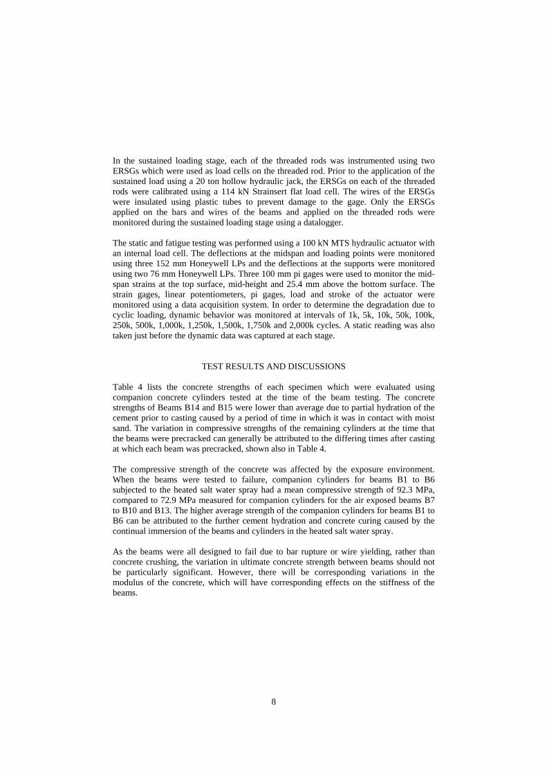
In the sustained loading stage, each of the threaded rods was instrumented using two ERSGs which were used as load cells on the threaded rod. Prior to the application of the sustained load using a 20 ton hollow hydraulic jack, the ERSGs on each of the threaded rods were calibrated using a 114 kN Strainsert flat load cell. The wires of the ERSGs were insulated using plastic tubes to prevent damage to the gage. Only the ERSGs applied on the bars and wires of the beams and applied on the threaded rods were monitored during the sustained loading stage using a datalogger. The static and fatigue testing was performed using a 100 kN MTS hydraulic actuator with an internal load cell. The deflections at the midspan and loading points were monitored using three 152 mm Honeywell LPs and the deflections at the supports were monitored using two 76 mm Honeywell LPs. Three 100 mm pi gages were used to monitor the mid-span strains at the top surface, mid-height and 25.4 mm above the bottom surface. The strain gages, linear potentiometers, pi gages, load and stroke of the actuator were monitored using a data acquisition system. In order to determine the degradation due to cyclic loading, dynamic behavior was monitored at intervals of 1k, 5k, 10k, 50k, 100k, 250k, 500k, 1,000k, 1,250k, 1,500k, 1,750k and 2,000k cycles. A static reading was also taken just before the dynamic data was captured at each stage.
TEST RESULTS AND DISCUSSIONS Table 4 lists the concrete strengths of each specimen which were evaluated using companion concrete cylinders tested at the time of the beam testing. The concrete strengths of Beams B14 and B15 were lower than average due to partial hydration of the cement prior to casting caused by a period of time in which it was in contact with moist sand. The variation in compressive strengths of the remaining cylinders at the time that the beams were precracked can generally be attributed to the differing times after casting at which each beam was precracked, shown also in Table 4. The compressive strength of the concrete was affected by the exposure environment. When the beams were tested to failure, companion cylinders for beams B1 to B6 subjected to the heated salt water spray had a mean compressive strength of 92.3 MPa, compared to 72.9 MPa measured for companion cylinders for the air exposed beams B7 to B10 and B13. The higher average strength of the companion cylinders for beams B1 to B6 can be attributed to the further cement hydration and concrete curing caused by the continual immersion of the beams and cylinders in the heated salt water spray. As the beams were all designed to fail due to bar rupture or wire yielding, rather than concrete crushing, the variation in ultimate concrete strength between beams should not be particularly significant. However, there will be corresponding variations in the modulus of the concrete, which will have corresponding effects on the stiffness of the beams.

9
The experimental program details are given in Table 5. The beams were precracked before they were subjected to the loading and exposure program. The beam stiffnesses prior to cracking were measured to be 14.0 - 17.5 kN per mm central deflection and were not significantly affected by the concrete compressive strengths, with the exception of beams B14 and B15, whose considerably lower concrete strengths resulted in a slight reduction in beam stiffness. Typically, either two or three cracks resulted within the constant moment region of the beams. The crack widths ranged between 0.2 and 0.3 mm. When the beams were unloaded, all the cracks closed although some residual displacements were recorded. A typical example of experimental precracked and postcracked behavior is shown in Figure 10. The measured precracking loads for the beams ranged from 16.4 kN to 18.4 kN. The cracking loads were calculated based on the measured tensile strengths of the companion concrete cylinders, and an allowance was made for the creep and shrinkage of concrete as well as bar or wire relaxation. The calculated cracking loads were lower than the measured values which suggested that either the concrete tensile strength was greater than the values measured using concrete cylinders or the prestressing losses were less than anticipated. The sustained loadings were applied for periods of 9 or 18 months. Due to the severe environmental conditions used in the chamber, all of the ERSGs attached to the prestressing bars and wires, and threaded rods did not function after 7 days. Although the wires of the ERSGs were insulated using plastic tubes, the damage of the gages due to environmental conditions could not be prevented. Furthermore, the gages attached to the bars and wires of the beams and threaded rods exposed to air showed unreliable results after 3 months. Therefore, the strain gage readings were not considered sufficiently reliable for comparison purposes. Beams subjected to environmental exposure for 9 months are shown in Figure 11. All beams subjected to cyclic loading survived two million cycles except beam B7 due to some experimental problems related to the testing equipment which was corrected for the rest of the testing program. The load versus midspan deflection behavior of all the beams tested to failure is shown in Figures 12 to 14. All the beams prestressed with CFRP bars showed a similar type of behavior except beam B1 which failed under a relatively low load. Reasons for this discrepancy are being investigated. The beams prestressed with steel wires behaved similarly to each other. In the following, comparisons are made between the test results, and comments made as to the significance of the variables considered in the test program. However, differences in concrete strength between the beams at the time of testing, due to differing types of environmental exposure, may also play a role.

10
Effect of Prestressing Material After precracking, the deflections of the beams prestressed with steel wires were always greater than those of the beams prestressed with CFRP bars under similar applied loads. The beams prestressed with steel wires were affected more significantly than the beams prestressed with CFRP bars under exposure to salt water spray. CFRP prestressed beams B5 and B6 were subjected to the same sustained load and salt water spray as steel prestressed beams B11 and B12. Whereas beams B5 and B6 survived the environmental exposure program for 18 months, beams B11 and B12 failed after 12 months due to the harsh environmental conditions. On inspection of the steel wires in beams B11 and B12 post failure, significant levels of corrosion were observed, which caused the wire rupture. This illustrates the benefit of using CFRP to prestress concrete in aggressive environments, in comparison with structures prestressed with steel. In general, the measured ultimate load capacities of the beams prestressed with CFRP bars were greater than those of the beams prestressed with steel wires. The maximum deflections at failure of the beams prestressed with steel wires were much greater than those of the beams prestressed with CFRP bars; an expected result given the ductility of the steel compared with the brittle CFRP. Beams B8 and B14, prestressed with CFRP bars and steel wires respectively, sustained 0.7 fpu of the bar or wire rupture strength and were exposed to air. On testing, the load and deflection of beam B8 at failure were 31 percent higher and 80 percent lower respectively compared to beam B14. Beams B9 (CFRP prestressed) and B15 (steel prestressed), were subjected to the same conditions as beams B8 and B14, but were tested cyclically. The load and deflection of beam B9 at failure were 16 percent higher and 92 percent lower respectively compared to beam B15. Effect of Cyclic Loading In all of the beams, a degradation in stiffness was observed as the number of cycles increased. Cyclically loading CFRP prestressed beams slightly reduced their maximum load capacity. When comparing beams with identical loading, exposure and test periods, cyclically loaded beams B4, B6 and B9 failed at loads 3.0 percent, 6.5 percent and 5.5 percent lower than the equivalent non-cyclically loaded beams B3, B5 and B8 respectively. The effect of cyclic loading on the steel prestressed beams was mixed. When other test parameters were identical, cyclically loaded beams B13 and B15 failed at loads 11.5 percent lower and 6.7 percent higher than non-cyclically loaded beams B10 and B14 respectively. These results indicate that beams prestressed with CFRP bars and steel wires are similarly capable of carrying cyclic loading within the vulnerable range of stresses. Effect of the Level of Sustained Loading and Duration of Loading The test results indicate that the stress range for sustained loading did not have a significant effect on the beams prestressed with CFRP bars. With other test parameters

11
identical, beam B4 in which the bars were subjected to a sustained stress of 0.7 fpu, failed at a load 2.3 percent lower than beam B2 in where the bars were subjected to a sustained stress of 0.55 fpu. Given that the beams prestressed with steel wires, beams B11 and B12 failed in the environmental chamber, it can be surmised that in aggressive environments, the stress range has severe effects on beams prestressed with steel wires. As the stress in steel wires increases, the crack width also increases resulting in an increased vulnerability of the steel wires to environmental effects. The beams prestressed with steel wires and subjected to air exposure, B10 and B14, were subjected to sustained loads for 9 months and 18 months respectively. The wires in beam B10 were subjected to a stress of 0.55 fpu compared to 0.7 fpu in beam B14. The combined effects of an increase in stress level and an increase in load duration were responsible for a 14 percent reduction in beam strength. Increasing the duration of the sustained loading on CFRP prestressed beams in an aggressive environment caused either no change or only a slight reduction in beam strength. This was evident in the behavior of two identical beams, B5 and B6 that were exposed to salt water spray for 18 months and which failed at almost identical loads to beams B3 and B4 that were in this environment for only 9 months. Effect of Environmental Exposure The environmental exposure to 15 percent by mass salt water spray and 54 ºC temperature did not reduce the strength of the beams prestressed with CFRP bars. This was evident in the behavior of beams B5 and B6 which were exposed to the salt water spray and which failed at load levels even slightly higher than beams B8 and B9 which were exposed to the air. However, the environmental exposure affected the beams prestressed with steel wires significantly resulting in the premature failure of beams B11 and B12 which failed after 12 months of environmental exposure whereas the identically loaded air exposed beams B14 and B15 survived the sustained loading for 18 months.
SUMMARY AND CONCLUSIONS Nine beams prestressed with CFRP bars were tested under various mechanical and environmental conditions. The parameters included in the program were the level of sustained stress in the bars (55 and 70 percent of fpu), the environmental exposure condition (air exposure and continuous exposure to 15 percent by mass salt water spray at 54 °C temperature within an environmental chamber), the length of time under sustained load (9 and 18 months) and the testing method (with or without application of cyclical loading prior to static testing to failure). Six similar beams prestressed with steel wires were also tested as control specimens for comparison purposes. The experimental program illustrated that CFRP prestressed beams exhibit comparable ultimate strength and fatigue strength properties in comparison to equivalent steel prestressed concrete beams. Furthermore, test results showed that the beams prestressed

12
with steel wires did not survive the environmental exposure over 12 months whereas the beams prestressed with CFRP bars survived up to the end of the 18 month long extreme environmental exposure, indicating the excellent durability of CFRP in the marine environment. As prestressing members, the brittle failure characteristic of CFRP bars is distinct to the ductile yielding of steel wires. This discrepancy is evident in the respective load deflection curves and differences in ultimate deflection of the beams at failure. The reduced ductility observed in the CFRP prestressed beams does not however characterise CFRP as an unsuitable choice for use in construction. The beam specimens were designed to fail by bar rupture or tendon yielding rather than concrete crushing, in order that the environmental and loading characteristics of the prestressing materials rather than the concrete could be evaluated. In practice, provided that design provision is made for the lack of CFRP ductility in comparison to steel, the research undertaken has indicated that CFRP prestressed concrete is a durable option when designing structures for use in offshore environments. Specifically, test results indicate that: 1. Generally, the CFRP prestressed beams retained greater strength compared to the
steel prestressed beams across the range of tests undertaken. 2. The beams prestressed with steel wires did not survive the environmental exposure
over 12 months whereas the beams prestressed with CFRP bars survived 18 months up to the end of the environmental exposure.
3. When precracked, the beams prestressed with steel bars could sustain induced stresses of 0.7 fpu, when exposed to air, but not when exposed to a heated salt water spray over a period of 12 months.
4. Cyclic loading had insignificant effects on beams prestressed with CFRP bars and steel wires.
5. A higher sustained bar stress in the beams prestressed with CFRP bars resulted in a slight reduction in beam strength. Beams prestressed with steel wires subjected to higher sustained stress levels become more vulnerable to environmental effects.
6. Exposing the beams prestressed with CFRP bars to 15 percent by mass salt water spray and 54 ºC temperature did not affect their behavior or cause any deterioration.
7. Increasing the salt water environmental exposure period for beams prestressed with CFRP bars affected neither the overall durability nor the strength.
8. Concurrently increasing the duration and level of sustained loading in the beams with steel prestressing wires exposed to air was found to cause a reduction in strength.
ACKNOWLEDGEMENTS The authors are grateful to SACAC, Holcim, Degussa, Grace Construction and VSL for donating many of the materials used in this project. Two of the authors, Dr Janet M. Lees (GR/S29669/01) and Paul Scott, were sponsored by the EPSRC (UK) during their time at

13
NCSU. We are also grateful to the technical staff of the NCSU, Constructed Facilities Laboratory, in particular Jerry Atkinson, Jeremy Bloom and Matt Vorys for their help.
REFERENCES
1. Agyei, B., “Fatigue of high strength concrete beams prestressed with carbon fibre reinforced polymer tendons,” M.Phil. Thesis, Department of Engineering, University of Cambridge, England, 2002.
2. Balazs, G. L. and Borosnyoi, A., “Long term behavior of FRP,” Composites in Construction: A Reality, 2001, pp. 84-91.
3. Micelli, F. and Nanni, A., “Durability of FRP rods for concrete structures,” Construction and Building Materials, Vol. 18, No. 7, 2004, pp. 491-503.
LIST OF NOTATIONS CFRP: Carbon fiber reinforced polymer ERSG: Electrical resistance strain gage f’c: Compressive strength of cylinder fpu: Ultimate tensile strength of the CFRP bar or steel wire FRP: Fiber reinforced polymer HRWRA: High range water reducing admixture HSS: Hollow square section LP: Linear potentiometer LVDT: Linear variable displacement transducer NCSU: North Carolina State University UC: University of Cambridge

14
Table 1 – Summary of the experimental program
Beam No
Reinforcing Material
Sustained Stress
Level in Bars and
Wires
Environmental Exposure
Duration of Combined
Sustained Load and Exposure
Program (months)
Cyclic Loading
B1 No B2 0.55 fpu Yes B3 No B4
9
Yes B5 No B6
CFRP Bar
Yes B11 No B12 Steel Wire
0.70 fpu
15 Percent Salt Water Spray
54 ºC Temperature 18
Yes B7 0.55 fpu 9 Yes B8 No B9
CFRP Bar 0.70 fpu 18 Yes B10 No B13 0.55 fpu 9 Yes B14 No B15
Steel Wire 0.70 fpu
Air
18 Yes
Table 2 – Concrete mixture design Material Amount Cement (kg/m3) 571.3 Silica Fume (kg/m3) 49.8 Sand (kg/m3) 1568.6 HRWRA (kg/m3) 10.29 Polypropylene Fibers (kg/m3) 1.03 Water (kg/m3) 205.9 water/cementitious material 0.33 Average Compressive Strength at Time of Beam precracking (at Approximately One Month) (MPa) 61.5
Table 3 – Material properties of the prestressing bars and wires Property CFRP Bar Steel Wire Nominal Diameter 4.0 mm 4.3 mm Area 12.57 mm2 14.52 mm2 Tensile Strength 2200 MPa 1940 MPa Modulus of Elasticity 161000 MPa 200000 MPa Elongation at Rupture 1.37% 5.21%

15
Table 4 – Test results of companion concrete cylinders
Beam No
f’c at Bar or Wire Detensioning
(MPa)
f’c at Precracking
(MPa)
f’c at Application of Sustained Load (MPa)
f’c at Loading
to Failure (MPa)
Tensile Strength
at Precracking
(MPa) B1 45.2 81.1 (38 days) 88.0 95.2 4.3 B2 46.9 67.0 (28 days) 76.9 84.6 4.6 B3 47.8 66.9 (28 days) 76.9 93.1 4.9 B4 52.3 82.5 (38 days) 84.9 100.1 5.1 B5 49.0 76.2 (59 days) 80.0 103.9 5.0 B6 49.6 65.9 (39 days) 63.7 82.3 4.7 B7 50.0 63.5 (39 days) 65.0 66.3 4.4 B8 49.4 78.0 (35 days) 84.0 83.2 5.2 B9 44.5 70.3 (35 days) 75.0 77.1 5.2
B10 - 63.1 (30 days) 66.1 70.3 4.2 B11 - 62.9 (30 days) 66.1 - 4.3 B12 - 70.8 (30 days) 73.6 - 4.3 B13 - 65.8 (30 days) 69.4 67.5 3.9 B14 36.8 47.0 (28 days) 51.6 55.2 3.9 B15 36.6 46.2 (28 days) 52.3 52.9 4.2
- No specimens were tested
Table 5 – Experimental program details Sustained Loading Cyclic Loading At Failure
Beam No
Precrack. Loads (kN)
Applied Load (kN)
Tendon Stress Level (fpu)
Load Range (kN)
Tendon Stress Range
(fpu)
Max. Load (kN)
Max. Defl. (mm)
B1 16.5 13.3 0.55 Static Testing Only 23.6 10.7 B2 16.4 13.3 0.55 16.0-18.7 0.65-0.75 30.8 12.0 B3 18.6 17.1 0.70 Static Testing Only 31.0 10.9 B4 16.4 17.1 0.70 16.0-18.7 0.65-0.75 30.1 12.2 B5 16.4 17.1 0.70 Static Testing Only 31.0 11.2 B6 17.7 17.1 0.70 16.0-18.7 0.65-0.75 29.0 10.0 B7 18.4 13.3 0.55 16.0-18.7 0.65-0.75 * B8 18.3 17.1 0.70 Static Testing Only 29.3 8.8 B9 18.0 17.1 0.70 16.0-18.7 0.65-0.75 27.7 4.0 B10 17.4 13.3 0.55 Static Testing Only 26.1 42.8 B11 17.4 17.1 0.70 B12 16.9 17.1 0.70 Failed under Environmental Exposure
B13 17.7 13.3 0.55 16.0-18.7 0.65-0.75 23.1 33.4 B14 17.3 17.1 0.70 Static Testing Only 22.4 52.1 B15 17.6 17.1 0.70 16.0-18.7 0.65-0.75 23.9 46.1
* Failed due to short of electric circuit of the actuator after 300000 cycles

16
a) Elevation b) Cross-section
Figure 1 – General view of the test specimens
Figure 2 – Prestressing rig
a) Dead end of CFRP bars b) Live end of CFRP bars
Figure 3 – Preparation details for specimens prestressed with CFRP
108 mm
203 mm
171 mm
64 mm Strong Floor
2130 mm
Spreader Beam
1905 mm
457 mm

17
a) Dead end of steel wires b) Live end of steel wires
Figure 4 – Preparation details for specimens prestressed with steel
Figure 5 – Test set-up for precracking
Figure 6 – Test set-up for sustained loading
Spreader Beam Beam
Specimens Supporting Steel Beam
Concrete Slab
Spring Threaded Rod

18
Figure 7 – Test set-up for sustained loading (air exposure)
Figure 8 – Test set-up for sustained loading (environmental exposure)
19
a) Before static test
b) After static test
Figure 9 – Test set-up for static and fatigue loading
0
5
10
15
20
25
0.0 0.2 0.4 0.6 0.8 1.0 1.2 1.4 1.6 1.8Midspan Deflection (mm)
Load
(kN
)
Figure 10 – Typical behavior at the precracking stage (beam B7)

20
Figure 11 – Specimens exposed to environmental conditions for 9 months
0
5
10
15
20
25
30
35
0 2 4 6 8 10 12 14Midspan Deflection (mm)
Load
(kN
)
B1
B3
B2
B4B5
B6
Figure 12 – Load vs. midspan deflection of beams prestressed with CFRP bars
(exposed to environmental conditions)

21
0
5
10
15
20
25
30
35
0 2 4 6 8 10 12 14Midspan Deflection (mm)
Load
(kN
)
B9
B8
Figure 13 – Load vs. midspan deflection of beams prestressed with CFRP bars
(exposed to air)
0
5
10
15
20
25
30
35
0 10 20 30 40 50 60Midspan Deflection (mm)
Load
(kN
)
B10
B13
B15
B14
Figure 14 – Load vs. midspan deflection of beams prestressed with steel wires
(exposed to air)