Dunkirk H2O
8
- Stainless Steel Single & Dual Coil Indirect Water Heaters - Storage Tanks - Hydronic Buffer Tanks Dunkirk H 2 O Innovative. Efficient. Dependable. Dunkirk.
Transcript of Dunkirk H2O
- Stainless Steel Single & Dual Coil Indirect Water Heaters- Storage Tanks- Hydronic Buffer Tanks
Dunkirk H2O
Innovative. Efficient. Dependable. Dunkirk.
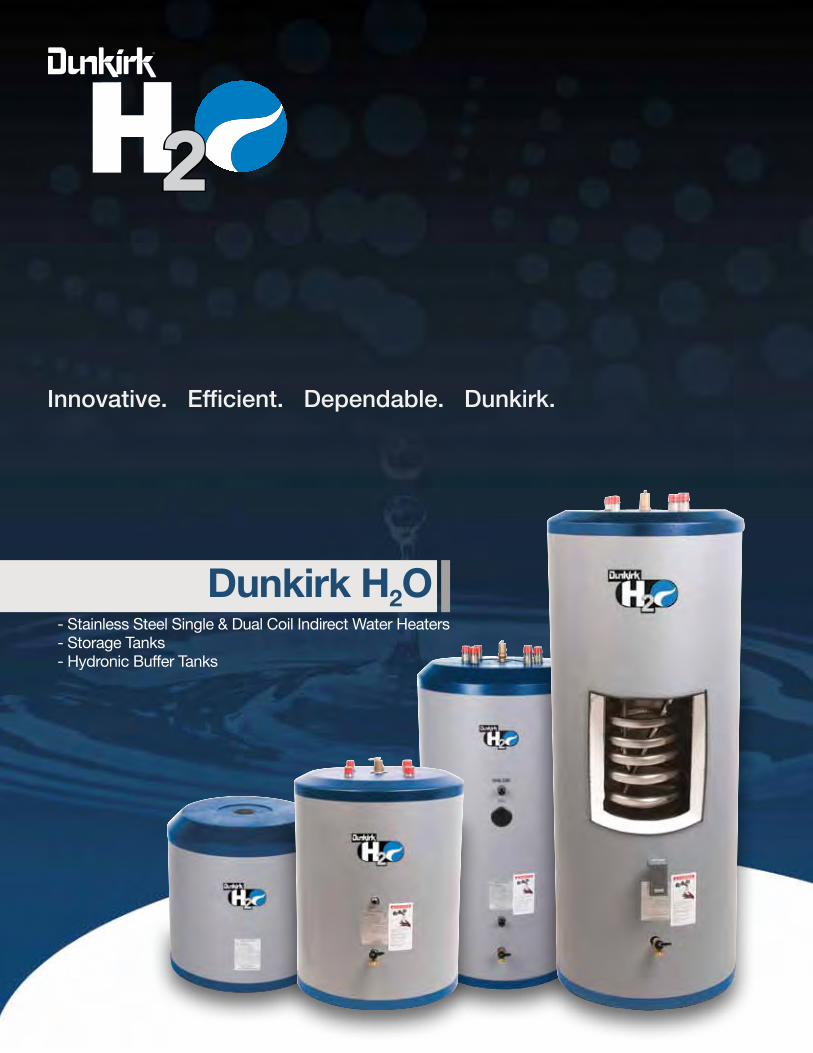
IntrODucIng tHe neW DunkIrk H2O SerIeS...A complete line of Stainless Steel, Single and Dual Coil Indirect Water Heaters, Storage Tanks, and Hydronic Buffer Tanks.
need An easy Domestic Hot Water Solution With A Low Operating cost and the Longevity Of Stainless Steel? Dunkirk H2O Stainless Steel Single coil Indirect Water Heaters
need A Hot Water Solution to Balance Input and Storage While reducing Short cycling? Dunkirk H2O Stainless Steel Storage tanks
need A Hot Water Solution For use With chillers, Heat Pumps, and Low Mass Boilers? Dunkirk H2O Stainless Steel Hydronic Buffer tanks
need A Hot Water Solution For Solar Applications Or Small Zones? Dunkirk H2O Stainless Steel Single & Dual coil Solar Water Heaters (Electric Back-Up can heat the tank if solar heat is unavailable)
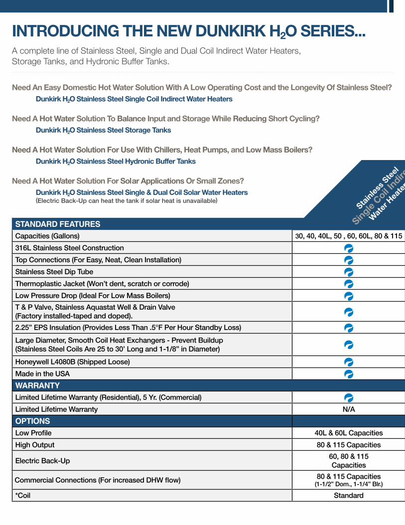
standard featuresCapacities (Gallons) 30, 40, 40L, 50 , 60, 60L, 80 & 115 30, 40, 60, 60L, 80 & 115 40, 60, 80 & 115 60, 80 & 115
316L Stainless Steel Construction
Top Connections (For Easy, Neat, Clean Installation)
Stainless Steel Dip Tube n/a
Thermoplastic Jacket (Won’t dent, scratch or corrode)
Low Pressure Drop (Ideal For Low Mass Boilers)
T & P Valve, Stainless Aquastat Well & Drain Valve (Factory installed-taped and doped).
2.25” EPS Insulation (Provides Less Than .5°F Per Hour Standby Loss)
Large Diameter, Smooth Coil Heat Exchangers - Prevent Buildup(Stainless Steel Coils Are 25 to 30’ Long and 1-1/8” in Diameter)
N/A *
Honeywell L4080B (Shipped Loose) N/A
Made in the USA
warrantyLimited Lifetime Warranty (Residential), 5 Yr. (Commercial) N/A N/A
Limited Lifetime Warranty N/A N/A
OPtIOnsLow Profile 40L & 60L Capacities 60L Capacities N/A N/A
High Output 80 & 115 Capacities N/A N/A N/A
Electric Back-Up60, 80 & 115 Capacities
N/A N/A60, 80 & 115 Capacities
Commercial Connections (For increased DHW flow) 80 & 115 Capacities(1-1/2” Dom., 1-1/4” Blr.)
80 & 115 Capacities (1-1/2”)
All Capacities(1-1/4”, 1-1/2”, 2”) N/A
*Coil Standard N/A 40, 60, 80 & 115 Capacities Standard
Stain
less S
teel
Single
coil Indire
ct
Wat
er H
eate
rs
®
standard featuresCapacities (Gallons) 30, 40, 40L, 50 , 60, 60L, 80 & 115 30, 40, 60, 60L, 80 & 115 40, 60, 80 & 115 60, 80 & 115
316L Stainless Steel Construction
Top Connections (For Easy, Neat, Clean Installation)
Stainless Steel Dip Tube n/a
Thermoplastic Jacket (Won’t dent, scratch or corrode)
Low Pressure Drop (Ideal For Low Mass Boilers)
T & P Valve, Stainless Aquastat Well & Drain Valve (Factory installed-taped and doped).
2.25” EPS Insulation (Provides Less Than .5°F Per Hour Standby Loss)
Large Diameter, Smooth Coil Heat Exchangers - Prevent Buildup(Stainless Steel Coils Are 25 to 30’ Long and 1-1/8” in Diameter)
N/A *
Honeywell L4080B (Shipped Loose) N/A
Made in the USA
warrantyLimited Lifetime Warranty (Residential), 5 Yr. (Commercial) N/A N/A
Limited Lifetime Warranty N/A N/A
OPtIOnsLow Profile 40L & 60L Capacities 60L Capacities N/A N/A
High Output 80 & 115 Capacities N/A N/A N/A
Electric Back-Up60, 80 & 115 Capacities
N/A N/A60, 80 & 115 Capacities
Commercial Connections (For increased DHW flow) 80 & 115 Capacities(1-1/2” Dom., 1-1/4” Blr.)
80 & 115 Capacities (1-1/2”)
All Capacities(1-1/4”, 1-1/2”, 2”) N/A
*Coil Standard N/A 40, 60, 80 & 115 Capacities Standard
Stain
less S
teel
Single
coil Indire
ct
Wat
er H
eate
rs
Stain
less S
teel
Dual coil S
olar
Wat
er H
eate
rs
Stain
less S
teel
Stora
ge ta
nk
Stain
less S
teel
Buffer t
anks
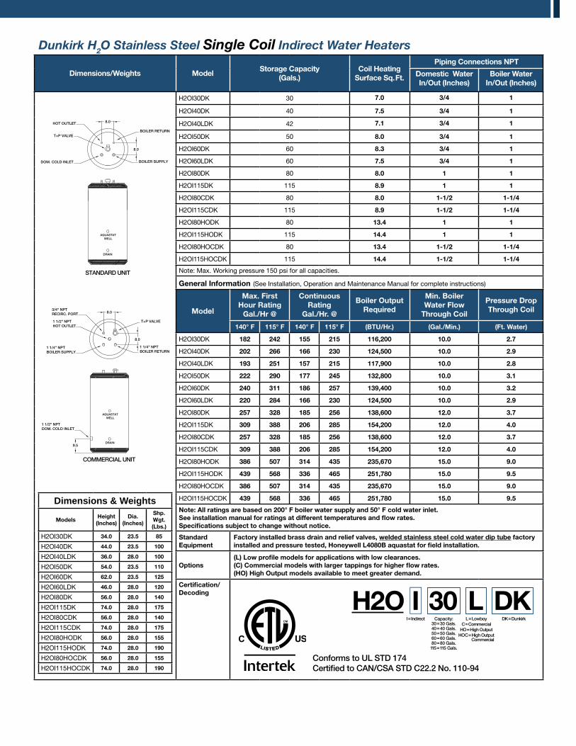
Dunkirk H2O Stainless Steel Single Coil Indirect Water Heaters
Dimensions/Weights ModelStorage capacity
(gals.)coil Heating
Surface Sq. Ft.
Piping connections nPt
Domestic Water In/Out (Inches)
Boiler Water In/Out (Inches)
Dimensions & Weights
ModelsHeight
(Inches)Dia.
(Inches)
Shp. Wgt.(Lbs.)
H2OI30DK 34.0 23.5 85
H2OI40DK 44.0 23.5 100
H2OI40LDK 36.0 28.0 100
H2OI50DK 54.0 23.5 110
H2OI60DK 62.0 23.5 125
H2OI60LDK 46.0 28.0 120
H2OI80DK 56.0 28.0 140
H2OI115DK 74.0 28.0 175
H2OI80CDK 56.0 28.0 140
H2OI115CDK 74.0 28.0 175
H2OI80HODK 56.0 28.0 155
H2OI115HODK 74.0 28.0 190
H2OI80HOCDK 56.0 28.0 155
H2OI115HOCDK 74.0 28.0 190
H2OI30DK 30 7.0 3/4 1
H2OI40DK 40 7.5 3/4 1
H2OI40LDK 42 7.1 3/4 1
H2OI50DK 50 8.0 3/4 1
H2OI60DK 60 8.3 3/4 1
H2OI60LDK 60 7.5 3/4 1
H2OI80DK 80 8.0 1 1
H2OI115DK 115 8.9 1 1
H2OI80CDK 80 8.0 1-1/2 1-1/4
H2OI115CDK 115 8.9 1-1/2 1-1/4
H2OI80HODK 80 13.4 1 1
H2OI115HODK 115 14.4 1 1
H2OI80HOCDK 80 13.4 1-1/2 1-1/4
H2OI115HOCDK 115 14.4 1-1/2 1-1/4
Note: Max. Working pressure 150 psi for all capacities.
general Information (See Installation, Operation and Maintenance Manual for complete instructions)
Model
Max. First Hour rating
gal./Hr @
continuous rating
gal./Hr. @
Boiler Output required
Min. BoilerWater Flow
through coil
Pressure Drop through coil
140° F 115° F 140° F 115° F (Btu/Hr.) (gal./Min.) (Ft. Water)
H2OI30DK 182 242 155 215 116,200 10.0 2.7
H2OI40DK 202 266 166 230 124,500 10.0 2.9
H2OI40LDK 193 251 157 215 117,900 10.0 2.8
H2OI50DK 222 290 177 245 132,800 10.0 3.1
H2OI60DK 240 311 186 257 139,400 10.0 3.2
H2OI60LDK 220 284 166 230 124,500 10.0 2.9
H2OI80DK 257 328 185 256 138,600 12.0 3.7
H2OI115DK 309 388 206 285 154,200 12.0 4.0
H2OI80CDK 257 328 185 256 138,600 12.0 3.7
H2OI115CDK 309 388 206 285 154,200 12.0 4.0
H2OI80HODK 386 507 314 435 235,670 15.0 9.0
H2OI115HODK 439 568 336 465 251,780 15.0 9.5
H2OI80HOCDK 386 507 314 435 235,670 15.0 9.0
H2OI115HOCDK 439 568 336 465 251,780 15.0 9.5
note: All ratings are based on 200° F boiler water supply and 50° F cold water inlet.See installation manual for ratings at different temperatures and flow rates.Specifications subject to change without notice.
Standard equipment
Factory installed brass drain and relief valves, welded stainless steel cold water dip tube factory installed and pressure tested, Honeywell L4080B aquastat for field installation.
Options(L) Low profile models for applications with low clearances. (c) commercial models with larger tappings for higher flow rates.(HO) High Output models available to meet greater demand.
certification/Decoding
T+P VALVE
1 1/4" NPTBOILER SUPPLY
1 1/4" NPTBOILER RETURN
1 1/2" NPTDOM. COLD INLET
AQUASTATWELL
DRAIN
8.0
8.0
9.5
3/4" NPTRECIRC. PORT
1 1/2" NPTHOT OUTLET
COMMERCIAL UNIT
8.0
T+P VALVE
BOILER SUPPLY
BOILER RETURN
AQUASTATWELL
DRAIN
STANDARD UNIT
8.0
HOT OUTLET
DOM. COLD INLET
H2OI=Indirect L=Lowboy
C=CommercialHO=High Output
HOC=High Output Commercial
DK=DunkirkCapacity:30=30 Gals.40=40 Gals.50=50 Gals.60=60 Gals.80=80 Gals.115=115 Gals.
L DK
Conforms to UL STD 174Certified to CAN/CSA STD C22.2 No. 110-94
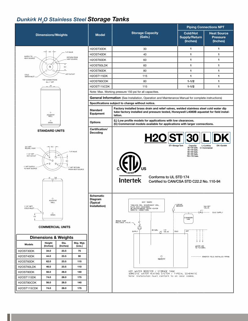
Dunkirk H2O Stainless Steel Storage Tanks
Dimensions/Weights ModelStorage capacity
(gals.)
Piping connections nPt
cold/HotSupply/return
(Inches)
Heat Source Pressure(Inches)
Dimensions & Weights
ModelsHeight
(Inches)Dia.
(Inches)Shp. Wgt.
(Lbs.)
H2OST30DK 34.0 23.5 75
H2OST40DK 44.0 23.5 90
H2OST60DK 62.0 23.5 115
H2OST60LDK 46.0 23.5 110
H2OST80DK 56.0 28.0 140
H2OST115DK 74.0 28.0 175
H2OST80CDK 56.0 28.0 140
H2OST115CDK 74.0 28.0 175
H2OST30DK 30 1 1
H2OST40DK 40 1 1
H2OST60DK 60 1 1
H2OST60LDK 60 1 1
H2OST80DK 80 1 1
H2OST115DK 115 1 1
H2OST80CDK 80 1-1/2 1
H2OST115CDK 115 1-1/2 1
Note: Max. Working pressure 150 psi for all capacities.
general Information (See Installation, Operation and Maintenance Manual for complete instructions)
Specifications subject to change without notice.
Standard equipment
Factory installed brass drain and relief valves, welded stainless steel cold water dip tube factory installed and pressure tested, Honeywell L4080B aquastat for field instal-lation.
Options(L) Low profile models for applications with low clearances.(c) commercial models available for applications with larger connections.
certification/Decoding
Schematic Diagram(typical Installation)
H2OST=Storage Tank L=Lowboy
C=CommercialDK=DunkirkCapacity:
30=30 Gals.40=40 Gals.60=60 Gals.80=80 Gals.115=115 Gals.
L DKST
TOP CONNECTIONS
ALL 1" NPT
COLD WATER INLET
SUPPLY TOHEAT SOURCE
HOT OUTLET
T+P VALVE
RETURN FROMHEAT SOURCE
8.0
8.0
STANDARD UNITS
AQUASTATWELL
DRAIN
T+P VALVE
1" NPT SUPPLYTO HEAT SOURCE
1" NPT RETURNFROM HEAT SOURCE
1 1/2" NPTCOLD INLET
AQUASTATWELL
DRAIN
COMMERCIAL UNITS
8.0
8.0
9.5
3/4" NPTRECIRC. PORT
1 1/2" NPTHOT OUTLET
Conforms to UL STD 174Certified to CAN/CSA STD C22.2 No. 110-94
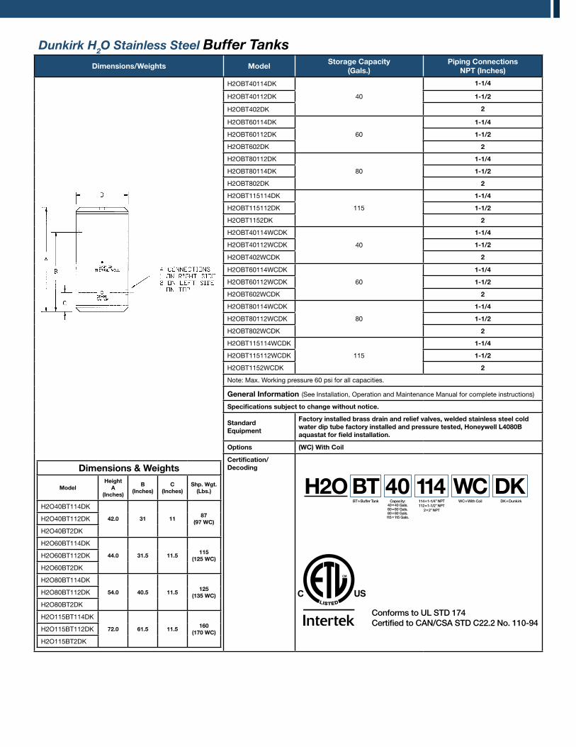
Dunkirk H2O Stainless Steel Buffer TanksDimensions/Weights Model
Storage capacity (gals.)
Piping connections nPt (Inches)
Dimensions & Weights
ModelHeight
A(Inches)
B(Inches)
c(Inches)
Shp. Wgt.(Lbs.)
H2O40BT114DK
42.0 31 1187
(97 Wc)H2O40BT112DK
H2O40BT2DK
H2O60BT114DK
44.0 31.5 11.5115
(125 Wc)H2O60BT112DK
H2O60BT2DK
H2O80BT114DK
54.0 40.5 11.5125
(135 Wc)H2O80BT112DK
H2O80BT2DK
H2O115BT114DK
72.0 61.5 11.5160
(170 Wc)H2O115BT112DK
H2O115BT2DK
H2OBT40114DK
40
1-1/4
H2OBT40112DK 1-1/2
H2OBT402DK 2
H2OBT60114DK
60
1-1/4
H2OBT60112DK 1-1/2
H2OBT602DK 2
H2OBT80112DK
80
1-1/4
H2OBT80114DK 1-1/2
H2OBT802DK 2
H2OBT115114DK
115
1-1/4
H2OBT115112DK 1-1/2
H2OBT1152DK 2
H2OBT40114WCDK
40
1-1/4
H2OBT40112WCDK 1-1/2
H2OBT402WCDK 2
H2OBT60114WCDK
60
1-1/4
H2OBT60112WCDK 1-1/2
H2OBT602WCDK 2
H2OBT80114WCDK
80
1-1/4
H2OBT80112WCDK 1-1/2
H2OBT802WCDK 2
H2OBT115114WCDK
115
1-1/4
H2OBT115112WCDK 1-1/2
H2OBT1152WCDK 2
Note: Max. Working pressure 60 psi for all capacities.
general Information (See Installation, Operation and Maintenance Manual for complete instructions)
Specifications subject to change without notice.
Standard equipment
Factory installed brass drain and relief valves, welded stainless steel cold water dip tube factory installed and pressure tested, Honeywell L4080B aquastat for field installation.
Options (Wc) With coil
certification/Decoding
Conforms to UL STD 174Certified to CAN/CSA STD C22.2 No. 110-94
H2OBT=Buffer Tank 114=1-1/4” NPT
112=1-1/2” NPT2=2” NPT
DK=DunkirkCapacity:40=40 Gals.60=60 Gals.80=80 Gals.115=115 Gals.
114WC=With Coil
WC DKBT 40
Buffer Tank Sizing - Calculating Capacity Dunkirk H2O buffer tanks are a simple, cost effective way to improve overall system efficiency by reducing unnecessary equipment short cycling. The recommended capacity or volume of a buffer tank is based on four variables.
1) The duration of the heating or cooling source “on time” (minutes). The desired length of “on time” for each run cycle depends on the type of equipment used. Heat pump and chiller manufacturers typically recommend a minimum of 5 to 10 minutes on time, and boiler manufacturers may recommend a minimum of 10 minutes “on time”. Check with your equipment manufacturer. Generally, the longer the “on time”, the higher the overall operating efficiency.
2) The minimum rate of heat input (BTU/HR). This is based on the heat pump or chiller output, or the boiler output at the minimum firing rate if the boiler has a variable input system that ramps input down as the demand decreases.
3) The minimum system load (BTU/HR). This is the demand placed on the system with the smallest zone calling for heat.4) The allowable tank temperature rise (deg. F). This varies depending on the type of heating or cooling system used, and on the
design of the distribution system. Chillers may require a tight, (6 deg. F), differential to assure good dehumidification and prevent freezing, heat pumps may require a (10 deg. F) differential to maintain a high COP, and boilers with hydronic heating distribution systems may require a differential anywhere between 10 to 40 deg. F depending on the application.
The following formula determines the tank volume:
DunkIrk H2O StAInLeSS SteeL BuFFer tAnkS
• Reduces chiller or boiler short cycling (Short cycling results in reduced operating efficiency and shorter equipment life)
• Used in systems having several low BTU cooling or heating loads calling at different times
• Full size tappings on buffer tank for peak performance (1-1/4”, 1-1/2”, and 2”)
• used in systems operating below the design load condition, which is most of the time.
H2O HyDrAuLIcALLy DecOuPLeD
to/FromBoiler/chiller/Heat-Pump
Buffer tanks
to/FromSystem
V = Buffer tank volume (gallons) T = desired heat source “on cycle” (min.)Q heat source = heat source output (BTU/HR) Q min. heat load = heat output to minimum loadTank temp rise (deg. F)
V = T X (Q heat input - Q min. heat load)
Tank temp. rise X 500
Water to Water Heat Pump Example: Town and Country Mechanical wants a minimum heat pump on time of 10 minutes. The heat pump output is 46,500 BTU/HR. The smallest zone is a 7,000 BTU/HR bathroom. The allowable temperature differential is 90 to 100 deg. F for the radiant heat zones.
= 79.0 Gallons minimum volume. Choose the H2O80BT buffer tank.V = 10 x (46,500 - 7,000)(100-90) x 500
Contractor Assistance: 800.325.5479 ®
P.O. Box 4729 Utica, New York 13504
tel: 315.797.1310 • fax: 315.797.3762www.dunkirk.com
Pn 240009330 rev. 2/12
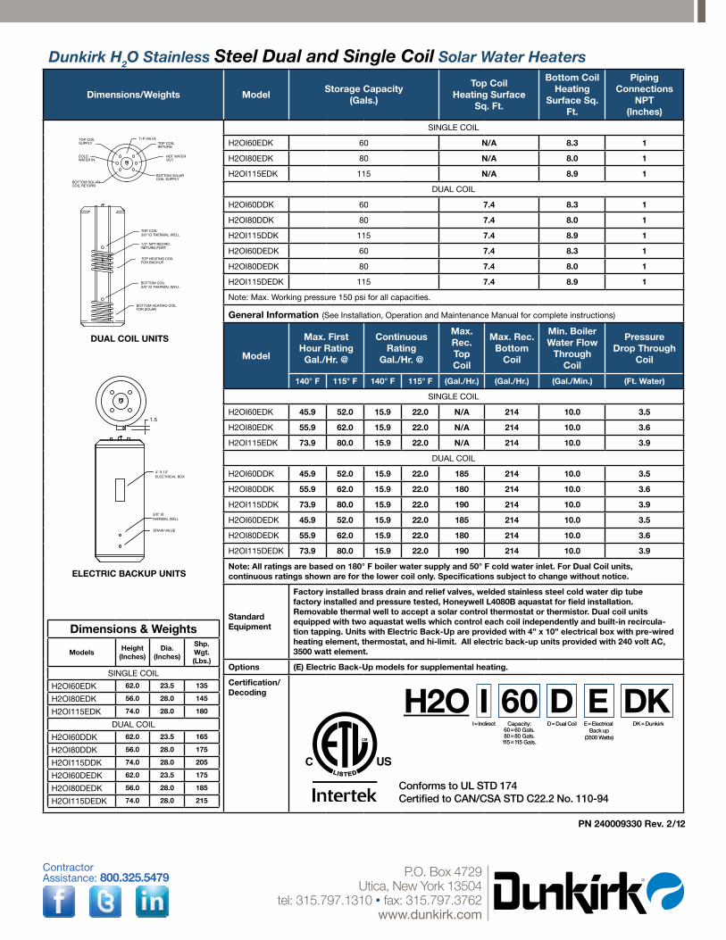
Dunkirk H2O Stainless Steel Dual and Single Coil Solar Water Heaters
Dimensions/Weights ModelStorage capacity
(gals.)
top coil Heating Surface
Sq. Ft.
Bottom coil Heating
Surface Sq. Ft.
Piping connections
nPt(Inches)
Dimensions & Weights
ModelsHeight
(Inches)Dia.
(Inches)
Shp. Wgt.(Lbs.)
SINGLE COIL
H2OI60EDK 62.0 23.5 135
H2OI80EDK 56.0 28.0 145
H2OI115EDK 74.0 28.0 180
DUAL COIL
H2OI60DDK 62.0 23.5 165
H2OI80DDK 56.0 28.0 175
H2OI115DDK 74.0 28.0 205
H2OI60DEDK 62.0 23.5 175
H2OI80DEDK 56.0 28.0 185
H2OI115DEDK 74.0 28.0 215
SINGLE COIL
H2OI60EDK 60 n/A 8.3 1
H2OI80EDK 80 n/A 8.0 1
H2OI115EDK 115 n/A 8.9 1
DUAL COIL
H2OI60DDK 60 7.4 8.3 1
H2OI80DDK 80 7.4 8.0 1
H2OI115DDK 115 7.4 8.9 1
H2OI60DEDK 60 7.4 8.3 1
H2OI80DEDK 80 7.4 8.0 1
H2OI115DEDK 115 7.4 8.9 1
Note: Max. Working pressure 150 psi for all capacities.
general Information (See Installation, Operation and Maintenance Manual for complete instructions)
Model
Max. First Hour ratinggal./Hr. @
continuous rating
gal./Hr. @
Max. rec. top coil
Max. rec. Bottom
coil
Min. BoilerWater Flow
through coil
Pressure Drop through
coil
140° F 115° F 140° F 115° F (gal./Hr.) (gal./Hr.) (gal./Min.) (Ft. Water)
SINGLE COIL
H2OI60EDK 45.9 52.0 15.9 22.0 n/A 214 10.0 3.5
H2OI80EDK 55.9 62.0 15.9 22.0 n/A 214 10.0 3.6
H2OI115EDK 73.9 80.0 15.9 22.0 n/A 214 10.0 3.9
DUAL COIL
H2OI60DDK 45.9 52.0 15.9 22.0 185 214 10.0 3.5
H2OI80DDK 55.9 62.0 15.9 22.0 180 214 10.0 3.6
H2OI115DDK 73.9 80.0 15.9 22.0 190 214 10.0 3.9
H2OI60DEDK 45.9 52.0 15.9 22.0 185 214 10.0 3.5
H2OI80DEDK 55.9 62.0 15.9 22.0 180 214 10.0 3.6
H2OI115DEDK 73.9 80.0 15.9 22.0 190 214 10.0 3.9
note: All ratings are based on 180° F boiler water supply and 50° F cold water inlet. For Dual coil units, continuous ratings shown are for the lower coil only. Specifications subject to change without notice.
Standard equipment
Factory installed brass drain and relief valves, welded stainless steel cold water dip tube factory installed and pressure tested, Honeywell L4080B aquastat for field installation. removable thermal well to accept a solar control thermostat or thermistor. Dual coil units equipped with two aquastat wells which control each coil independently and built-in recircula-tion tapping. units with electric Back-up are provided with 4” x 10” electrical box with pre-wired heating element, thermostat, and hi-limit. All electric back-up units provided with 240 volt Ac, 3500 watt element.
Options (e) electric Back-up models for supplemental heating.
certification/Decoding
Conforms to UL STD 174Certified to CAN/CSA STD C22.2 No. 110-94
BOTTOM SOLARCOIL RETURN
TOP COILSUPPLY
BOTTOM SOLAR COIL SUPPLY
T+P VALVETOP COILRETURN
COLD WATER IN
HOT WATEROUT
BOTTOM HEATING COILFOR SOLAR
BOTTOM COIL3/8" ID THERMAL WELL
TOP HEATING COILFOR BACKUP
TOP COIL3/8" ID THERMAL WELL
1/2" NPT RECIRC.RETURN PORT
DUAL COIL UNITS
DRAIN VALVE
3/8" IDTHERMAL WELL
4" X 10"ELECTRICAL BOX
1.5
ELECTRIC BACKUP UNITS
H2OI=Indirect D=Dual Coil DK=DunkirkCapacity:
60=60 Gals.80=80 Gals.115=115 Gals.
D60E=Electrical
Back up(3500 Watts)
E DK
![Central Metabolism Cofactor Biosynthesis · ppp9 pi h h2o ppi h h2o h2o dad-5 h[p] atp adp h pi h2o succoa lipoate atp glx 2p4c2me xu5p-D h2o cbl1 ppi h[e] h2o h dad-5 gthrd asp-L](https://static.fdocuments.us/doc/165x107/5f47678d7025ea6bb340bf3d/central-metabolism-cofactor-biosynthesis-ppp9-pi-h-h2o-ppi-h-h2o-h2o-dad-5-hp.jpg)