Dune-ND ArgonCube 2x2 @ LArTF Low-Noise Detector Power Plan
31
Linda Bagby 2x2 Planning Meeting April 5, 2021 Dune-ND ArgonCube 2x2 @ LArTF Low-Noise Detector Power Plan
Transcript of Dune-ND ArgonCube 2x2 @ LArTF Low-Noise Detector Power Plan

Linda Bagby
2x2 Planning Meeting
April 5, 2021
Dune-ND
ArgonCube 2x2 @ LArTF
Low-Noise Detector Power Plan

LArTF Detector low-noise AC Distribution
• LArTF has two DS 75kVA XFMRs, A and B.
• Each power panel has 42 branch circuits.
• XFMR A has eight 208/3-phase 30A branch
circuits configured.
– Outlets are distributed along the east side of the
platform inside currently used electronics racks.
– Each rack is equipped with 208/3-phase PDUs
providing three banks of 120V/30A services, 8
outlets each. (power not the issue)
• XFMR B has 3 branch circuits.
– 2 branch circuits are located on the north end of
the platform, 1 on the south end.
04.05.20 Linda Bagby | Electronics Integration2

Detector power schematic
04.05.20 Linda Bagby | Electronics Integration3
• XFMRS located in pit
• Power panels
located on north end
of platform

LArTF Geometry
04.05.20 Linda Bagby | Electronics Integration4
• Power panels, Z-mon CT, and monitor chassis located on
the north end of platform.
• 2x2 in the garage area.
• XFMR A: green, XFMR B: blue, Building: red
NorthGarageArea
LIZ

Upgrade Impedance Monitoring system-if possible
04.05.20 Linda Bagby | Electronics Integration5
• The facility is equipped with the first Impedance Monitor
system installed at Fermi with a hand wound saturable
inductor
• Custom designed, commercially built, inductors are now
available.
• Newer design of Impedance monitor chassis is available.

Requirements for low-noise AC Distribution design
04.05.20 Linda Bagby | Electronics Integration6
• Power down mBooNE electronics via power panel A circuit breakers.
• Re-terminate hard wired AC power cords, located inside mBooNE racks, with twist and lock plugs suitable for a jumper cable from the cable tray above the mBooNE racks to the 2x2 electronics racks.
– assumes a 3 month temporary installation
• Disconnect the mBooNE cryostat ground cable, associated with XFMR A, and run new cable to 2x2 cryostat from PP A.
– Requires electrician.
• If Z-mon upgraded (includes SI, CT, chassis)
– Lock out XFMRs.
– Install new saturable inductors in pit.
– Requires electrician.
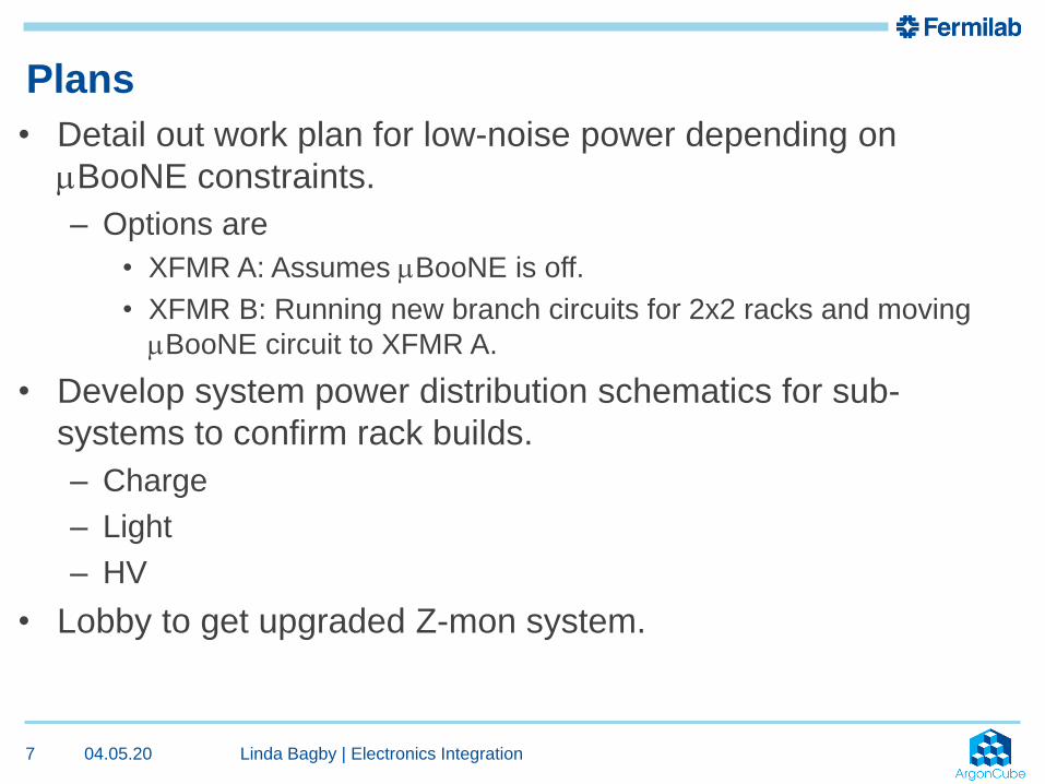
Plans
04.05.20 Linda Bagby | Electronics Integration7
• Detail out work plan for low-noise power depending on
mBooNE constraints.
– Options are
• XFMR A: Assumes mBooNE is off.
• XFMR B: Running new branch circuits for 2x2 racks and moving
mBooNE circuit to XFMR A.
• Develop system power distribution schematics for sub-
systems to confirm rack builds.
– Charge
– Light
– HV
• Lobby to get upgraded Z-mon system.

04.05.20 Linda Bagby | Electronics Integration8
Questions?

04.05.20 Linda Bagby | Electronics Integration9
Rack Protection System and AC Distribution Solutions
120V/20A (16A cont.)
208V/3f/30A (24A cont. / f )
120V/30A (24A cont.)
Rack Protection Chassis
Sensor System 2W-B or 2WT-BPhotoelectric
smoke/temp (135°F) sensor

Infrastructure cost
04.05.20 Linda Bagby | Electronics Integration10
AC Solutions Cost (each) Notes
120V/20A Service 16A total
Rack Protection (RPS) 350.00$ Custom Design
Smoke Detector 30.00$ Sensor Systems 2W-B
SurgeX (SX-1120-RT) 650.00$ 6 switched, 2 unswitched, 1 courtesy
Interlock cable 25.00$ Mueller BU-1150-C-60-0, 5ft
Total 1,055.00$
208/3p/30A Service 24A each phase
Rack Protection (RPS) 350.00$
Smoke Sensor 30.00$
AC Switch Box 1,000.00$ Custom design, includes power cord
Eaton 850.00$ PW309BA0U409
Total 2,230.00$
120V/30A Service 24A each phase
Rack Protection (RPS) 350.00$
Smoke Sensor 30.00$
AC Switch Box 30 600.00$ Custom design, includes power cord
APC 850.00$ AP8932, managed
Slow Controls 400.00$ Custom Design
Total 2,230.00$
AC DISTRIBUTION SOLUTIONS

First Pass DC Requirements
04.05.20 Linda Bagby | Electronics Integration11

Light Readout Concept Requirements• LV ASIC Bias (LMH6624)
– +/-5V, 4A
– or +5 to +12V, ?A
• LV ASIC Bias Splitter
– passive (1→402 ch)
• PGA (VGA) LV PS
– 2 options I/P
• +5V/90A
• +/-5V/45A
• LV SiPM Bias
– 20V/?A
• SiPM Common Bias
– -40 to 57V/?A
• SiPM Com Bias Splitter
– Passive (1→134 ch)
04.05.20 Linda Bagby | Electronics Integration12
LV ASIC BIAS+/- 5V
4A
LV PGA BIAS+5V/90A
OR+/-5V / 45A
Is this for all 4 modules or each module?
Need PS

04.05.20 Linda Bagby | Electronics Integration13
• LV ASIC Bias (LMH6624)
– +/-5V, 4A
• PGA (VGA) LV
PS
– 2 options I/P
• +5V/90A
• +/-5V/45A
MINOS
Minder

MINOS Master
04.05.20 Linda Bagby | Electronics Integration14
• LV ASIC Bias (LMH6624)
– +/-5V, 4A
• PGA (VGA) LV PS
– 2 options I/P
• +5V/90A
• +/-5V/45A

System distribution example
04.05.20 Linda Bagby | Electronics Integration15

Connectorization—Details we need...
04.05.20 Linda Bagby | Electronics Integration16
• Connector and cable part number
• Signal name
• Polarity
• Pin designation
• Conductor color
• Shield termination location

SEDR and ORC Information
04.05.20 Linda Bagby | Electronics Integration17

04.05.20 Linda Bagby | Electronics Integration18
What is an ORC Review?
• Prior to operation, experiments, projects, and R&D (Research and Development)
efforts may require an ES&H (Environment, Safety, and Health) review depending
on the hazards or risks involved. The ES&H review may consist of multiple reviews
by subject matter experts (SME’s) from a variety of committees depending upon the
hazards involved. The ES&H review procedure is designed to review these projects
and to ensure proper documentation and reviews have been conducted. The
Operational Readiness Clearance (ORC) process is used to capture the
recommendations, findings, and ultimate recommendation to operate from these
various committees.
http://esh-docdb.fnal.gov/cgi-bin/ShowDocument?docid=3311

04.05.20 Linda Bagby | Electronics Integration19
ORC or NOT????
• All equipment, temporary or ‘production’, requires a review at some level.
• Angela Aparicio and the responsible engineer for the various disciplines looks at
each case to determine the level of the review.
– Electrical/Electronics equipment: Linda Bagby

04.05.20 Linda Bagby | Electronics Integration20
Custom vs Commercial Equipment
• Custom electrical equipment is defined as electronics that are not commercially
available.
– Printed circuit boards designed by anyone other than a commercial company (engineer,
collaborator, physicist, post doc, grad student).
– Chassis containing a collection of commercial parts with internal wiring completed by the
user.
– Modified commercial equipment.
• Extending a power cord.
– Equipment that does not contain a Nationally Recognized Testing Laboratory (NRTL) seal.
• Commercial electrical equipment typically has a NRTL seal.

04.05.20 Linda Bagby | Electronics Integration21
Guidance Sources
All experiments within the Neutrino Division (ND) follow the Particle Physics Division
(PPD) guidelines for Operational Readiness Clearance (ORC) reviews and utilize the
Fermilab Office of Program Planning TSW (Technical Scope of Work) and ORC
webpage.
• Link to the Particle Physics Division Operational Readiness Clearance (PPD ORC)
http://www-ppd.fnal.gov/ESHBMGOffice/orc.html
• Office of Program Planning
http://programplanning.fnal.gov/tsw_orc/
• Link to the Fermilab Environment, Safety and Health Manual (FESHM)
http://eshq.fnal.gov/manuals/feshm/

04.05.20 Linda Bagby | Electronics Integration22
Where does one start??
• Use the PPD ORC page to determine the hazards for a given subsystem
– http://www-ppd.fnal.gov/ESHBMGOffice/orc.html
• Hazard Checklist
– http://www-ppd.fnal.gov/eshbmgOffice/SafetyPDFs/HazardIDChecklist.pdf
• Hazards include:
– Flammable (Gases or Liquids)
– Gases
– Chemicals
– Radioactive Sources
– Target Materials
– Nuclear Materials
– Class 3b or Class 4 Lasers
– Electrical Equipment
– Mechanical Structures
– Vacuum Vessels
– Pressure Vessels and Pressure Piping
– Fire and Life Safety
– Radiation Safety
– Trip, Fall, and Strain relief considerations

04.05.20 Linda Bagby | Electronics Integration23
3 Step Process: Step 1
• Safety Engineering Design Review (SEDR)
• Performed on custom designed or modified commercial equipment.
• Requirements (chassis level)
• A SEDR Request document containing:
– General description of the chassis.
– Simplified (block) electrical diagram of the chassis, including
commercial components, with special emphasis on power handling
issues. These must be of sufficient detail that reviewers can verify the
experimenters have observed good systems engineering practices and
have used proper fusing, wire sizes, insulation, termination, etc.
– Schematics, Artwork, Bill of Materials, of custom manufactured circuitry
or modifications of commercial components of similar detail.
– Sample of the equipment to be reviewed.
– An Engineering Note is useful.
• Should be done during the PRE-PRODUCTION phase of a design to allow time to
complete any ‘required’ findings before going into production.

04.05.20 Linda Bagby | Electronics Integration24
3 Step Process: Step 2
• partial Operational Readiness Clearance (pORC)
• A mechanism for powering up one subsystem while others are being installed or
assembled.
• Performed on a subsystem’s fully populated electronics racks or a subsystem’s collection
of equipment which will be operated at a test stand, experimental building, or in a
beamline enclosure.
• Includes all intra AND inter rack connections, including external AC Distribution.
• Requirements (rack or subsystem level)– Simplified (block) electrical diagram of entire installation, including commercial components, with special
emphasis on power handling issues. These must be of sufficient detail that reviewers can verify the
experimenters have observed good systems engineering practices and have used proper fusing, wire sizes,
insulation, termination, etc.
– Line diagrams of custom manufactured circuitry or modifications of commercial components of similar
detail.
– Fully populated rack.
• Can be done at experiment’s enclosure or other site before racks are moved to enclosure.
• Includes SEDR Findings report, subsequent actions, and final approval.

04.05.20 Linda Bagby | Electronics Integration25
3 Step Process: Step 3
• Final Operational Readiness Clearance Walkthrough (ORC)
• Documentation consists of a ‘wrapper’ around all of the subsystem partial Operational
Readiness Clearance review findings and responses.
• This is a final walkthrough by safety to insure the installation is complete and ready to go.

04.05.20 Linda Bagby | Electronics Integration26
On the Particle Physics Division Operational Readiness Clearance webpage, under
Electrical Equipment, there are 2 useful links to use as guidance.
– http://www-ppd.fnal.gov/ESHBMGOffice/orc.html
• Electrical Safety ORC Review Guidelines
– http://esh-docdb.fnal.gov/cgi-bin/ShowDocument?docid=3270
• Electrical Design Standards
– http://esh-docdb.fnal.gov/cgi-bin/ShowDocument?docid=2781
To assist in the preparation of electronics rack builds and a method of organizing
documentation for reviews, operations, and maintenance.
• Rack Build tool
• Electronics Documentation Links
Electrical Equipment Support

04.05.20 Linda Bagby | Electronics Integration27
• List all rack equipment
• Useful to have a system block diagram
Rack Build Example
NRTL Seal and CE Mark
04.05.20 Linda Bagby | Electronics Integration28

04.05.20 Linda Bagby | Electronics Integration29
Electrical Equipment Approvals
• Per the Department of Energy’s prime directive to Fermilab, Fermilab is required
to follow the National Electrical Codes (NEC) and Occupational Health and
Safety Administration (OSHA) guidelines.
• OSHA requires all commercial equipment to be approved by the electrical
Authority Having Jurisdiction (AHJ).
• The AHJ for Fermilab is David Mertz.
• Nationally Recognized Testing Laboratories list:
https://www.osha.gov/dts/otpca/nrtl/nrtllist.html

04.05.20 Linda Bagby | Electronics Integration30
CE Mark
• OSHA requires Nationally Recognized Testing Laboratories (NRTLs) to be
independent from the manufacturer.
• The CE mark is a manufacturer’s self-certification, therefore, the mark does not
meet OSHA requirements.
• https://www.osha.gov/dts/otpca/nrtl/nrtl_faq.html
• For custom designs or CE marked equipment, there are 3 solutions:
– Safety Engineering Design Review (SEDR).
– Have vendor obtain a Nationally Recognized Testing Laboratory (NRTL) listing so the
equipment bears a NRTL seal.
– Have a Nationally Recognized Testing Laboratory (NRTL) representative perform a field
inspection of the equipment on site.

04.05.20 Linda Bagby | Electronics Integration31
• A ‘low noise’ AC Distribution system will be used at Fermilab.
• Equipment must operate at voltages/frequency readily available on the US power
grid.
• All set-ups must have a safety review. Level of the review is based on hazards.
• Generate block diagrams of all systems.
• Power requirements (voltage/current) must be provided for all equipment.
– Identify building or detector power.
– Use the Rack Build tool to itemize equipment.
Summary