Dull Grade Book 2008
103
ROLLER CONE DULL GRADING MANUAL
-
Upload
manuel-perdomo -
Category
Documents
-
view
913 -
download
1
Transcript of Dull Grade Book 2008
ROLLER CONEDULL GRADING
MANUAL
Roller Cone Dull Grading Manual
The Smith Bits definitions and guidelines shown within are NOT IADC standards. They were created solely for internal purposes to reduce ambiguities and to improve our consistency in grading dull bits
within the current IADC structure.
P.O. Box 60068 • Houston, Texas 77205-0068
U.S. And Canada: 800/US SMITH • Tel. 281/443-3370
Fax: 281-233-5237 Internet: http://www.smithbits.com
Copyright © 2008 Smith International, Inc. All rights reserved.
ST-2067 • 25M • 01/08
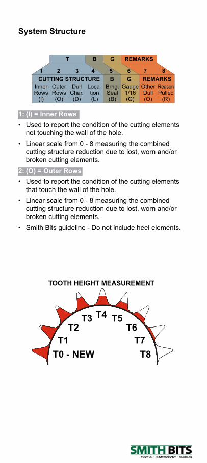
1: (I) = Inner Rows• Used to report the condition of the cutting elements
not touching the wall of the hole.• Linear scale from 0 - 8 measuring the combined
cutting structure reduction due to lost, worn and/or broken cutting elements.
2: (O) = Outer Rows• Used to report the condition of the cutting elements
that touch the wall of the hole.• Linear scale from 0 - 8 measuring the combined
cutting structure reduction due to lost, worn and/or broken cutting elements.
• Smith Bits guideline - Do not include heel elements.
System Structure
InnerRows
(I)
OuterRows(O)
DullChar.(D)
Loca-tion(L)
Brng.Seal(B)
Gauge1/16(G)
OtherDull(O)
ReasonPulled
(R)
CUTTING STRUCTURE B G REMARKS
BT G REMARKS
1 2 3 4 5 6 7 8
TOOTH HEIGHT MEASUREMENT
T0 - NEW T8T1
T2T3 T4
T7T6
T5
Roller Cone Dull Grading Manual
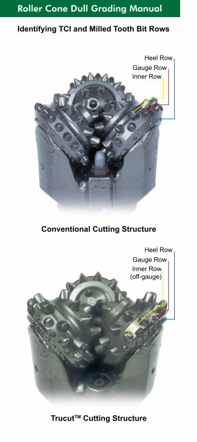
Identifying TCI and Milled Tooth Bit Rows
Conventional Cutting Structure
TrucutTM Cutting Structure
Inner Row (off-gauge)
Gauge RowHeel Row
Inner RowGauge Row
Heel Row
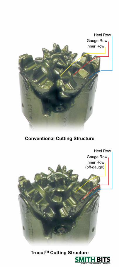
TrucutTM Cutting Structure
Conventional Cutting Structure
Inner Row (off-gauge)
Gauge RowHeel Row
Inner RowGauge Row
Heel Row
Roller Cone Dull Grading Manual
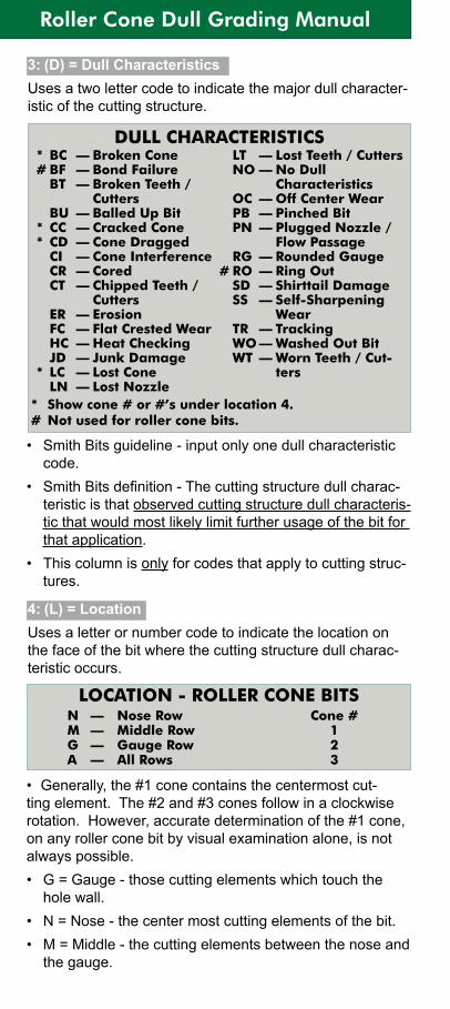
4: (L) = LocationUses a letter or number code to indicate the location on the face of the bit where the cutting structure dull charac-teristic occurs.
3: (D) = Dull CharacteristicsUses a two letter code to indicate the major dull character-istic of the cutting structure.
• Smith Bits guideline - input only one dull characteristic code.
• Smith Bits definition - The cutting structure dull charac-teristic is that observed cutting structure dull characteris-tic that would most likely limit further usage of the bit for that application.
• This column is only for codes that apply to cutting struc-tures.
• Generally, the #1 cone contains the centermost cut-ting element. The #2 and #3 cones follow in a clockwise rotation. However, accurate determination of the #1 cone, on any roller cone bit by visual examination alone, is not always possible.• G = Gauge - those cutting elements which touch the
hole wall.• N = Nose - the center most cutting elements of the bit.• M = Middle - the cutting elements between the nose and
the gauge.
DULL CHARACTERISTICS* BC — Broken Cone# BF — Bond Failure BT — Broken Teeth /
Cutters BU — Balled Up Bit* CC — Cracked Cone* CD — Cone Dragged CI — Cone Interference CR — Cored CT — Chipped Teeth /
Cutters ER — Erosion FC — Flat Crested Wear HC — Heat Checking JD — Junk Damage* LC — Lost Cone LN — Lost Nozzle
LT — Lost Teeth / Cutters NO — No Dull
Characteristics OC — Off Center Wear PB — Pinched Bit PN — Plugged Nozzle /
Flow Passage RG — Rounded Gauge# RO — Ring Out SD — Shirttail Damage SS — Self-Sharpening
Wear TR — Tracking WO — Washed Out Bit WT — Worn Teeth / Cut-
ters
* Show cone # or #’s under location 4. # Not used for roller cone bits.
LOCATION - ROLLER CONE BITSN — Nose Row Cone #M — Middle Row 1G — Gauge Row 2A — All Rows 3
• A = All rows• Cone numbers• Smith Bits guidelines - a maximum of two characters to
be input.5: (B) = Bearings / Seals
Non-Sealed BearingsLinear scale from 0 - 8 estimating bearing life used.
Sealed BearingsE - Seals effectiveF - Seals failedN - Not able to grade
Smith Bits guidelines• This column is used to indicate condition of the bearing
and seal assembly. If either component in the assembly has failed, then the code is F.
• If any portion of the bearing is exposed or missing, it is considered an ineffective (F) assembly.
• Use N if unable to determine the condition of both com-ponents.
• Smith Bits grades each assembly separately.• If grading all assemblies as one, list the worst case.
Sealed Bearing Checklist
6: (G) = GaugeUsed to report the undergauge condition of the cutting ele-ments that touch the wall of the hole.• Use only a nominal ring gauge to gauge a dull bit.• New bits are built to API specifications. Ring gauges
built for new bits have the tolerances listed in the table below and should not be used for gauging dull bits.
API Tolerance For New Bits Bit Size API Tolerance 5 5/8 - 13 3/4 + 1/32 : -0 14 - 17 1/2 + 1/16 : -0 17 5/8 & larger + 3/32 : -0
Items To Check When Determining Seal / Bearing Effectiveness
Ability to rotate cone Cone springback Seal squeakInternal sounds Weeping grease
Shale burn Shale packingGaps - backface or throatBearing letdown - inner or
outer

Roller Cone Dull Grading Manual
Smith Bits guidelines• Round to nearest 1/16”.• Bits with bearing/seal failures: can measure amount
out of gauge as long as cones do not have any axial or radial movement.
• Measurement to be made on either gauge or heel ele-ments which ever is closer to gauge.
• Applies to cutting structure elements only.• Ensure that a nominal ring gauge is used. If nominal
ring gauges are not available, true gauge condition can not be determined.
7: (O) = Other Dull CharacteristicsUsed to report any dull characteristics.
Measured Distance3 Cone Bits
AMOUNT OUT OF GAUGE = MEASURED DISTANCE X 2/3
Measured Distance2 Cone Bits
AMOUNT OUT OF GAUGE = MEASURED DISTANCE
DULL CHARACTERISTICS BC — Broken Cone# BF — Bond Failure BT — Broken Teeth /
Cutters BU — Balled Up Bit CC — Cracked Cone CD — Cone Dragged CI — Cone Interference CR — Cored CT — Chipped Teeth /
Cutters ER — Erosion FC — Flat Crested Wear HC — Heat Checking JD — Junk Damage LC — Lost Cone* LN — Lost Nozzle
LT — Lost Teeth / Cutters NO — No Dull
Characteristics OC — Off Center Wear* PB — Pinched Bit* PN — Plugged Nozzle /
Flow Passage RG — Rounded Gauge# RO — Ring Out* SD — Shirttail Damage SS — Self-Sharpening
Wear TR — Tracking* WO — Washed Out Bit WT — Worn Teeth / Cut-
ters
* Used only in the ‘Other Dull Characteristics’ column. # Not used for roller cone bits.
8: (R) = Reason PulledUsed to report the reason pulled.
BHA — Change Bottom Hole Assembly CM — Condition Mud CP — Core Point DMF — Downhole Motor Failure DP — Drill Plug DSF — Drill String Failure DST — Drill Stern Testing DTF — Downhole Tool Failure FM — Formation Change HP — Hole Problems HR — Hours on Bit LIH — Left in Hole LOG — Run Logs PP — Pump Pressure PR — Penetration Rate RIG — Rig Repair RS — Retrieve Survey TD — Total Depth / Casing Depth TQ — Torque TW — Twist Off WC — Weather Conditions WO — Washout in Drill String
Roller Cone Dull Grading Manual
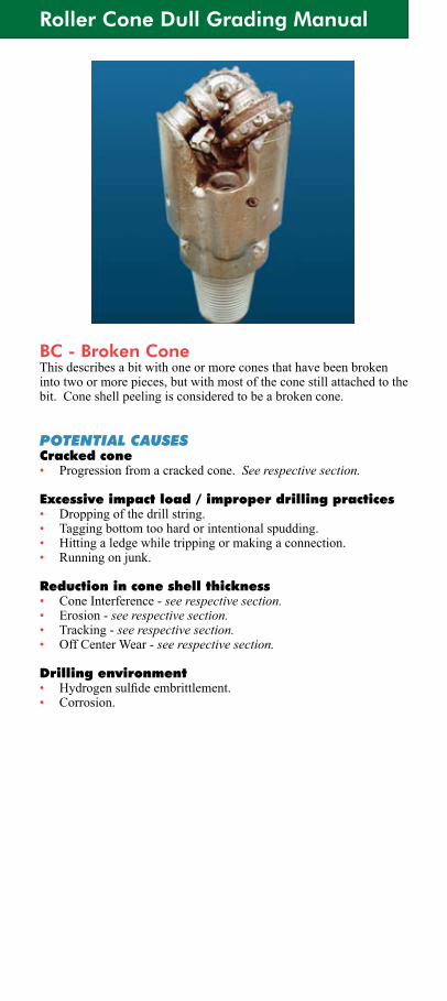
BC - Broken ConeThis describes a bit with one or more cones that have been broken into two or more pieces, but with most of the cone still attached to the bit. Cone shell peeling is considered to be a broken cone.
POTENTIAL CAUSESCracked cone• Progression from a cracked cone. See respective section.
Excessive impact load / improper drilling practices• Dropping of the drill string.• Tagging bottom too hard or intentional spudding.• Hitting a ledge while tripping or making a connection.• Running on junk.
Reduction in cone shell thickness• Cone Interference - see respective section.• Erosion - see respective section.• Tracking - see respective section.• Off Center Wear - see respective section.
Drilling environment• Hydrogensulfideembrittlement.• Corrosion.
Smith Tool Dull Grading Manual
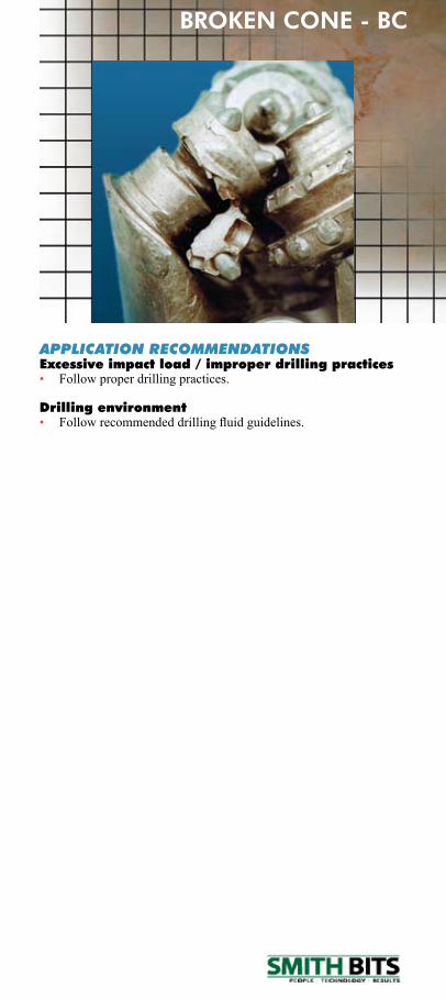
APPLICATION RECOMMENDATIONSExcessive impact load / improper drilling practices• Follow proper drilling practices.
Drilling environment• Followrecommendeddrillingfluidguidelines.
BROKEN CONE - BC
Roller Cone Dull Grading Manual
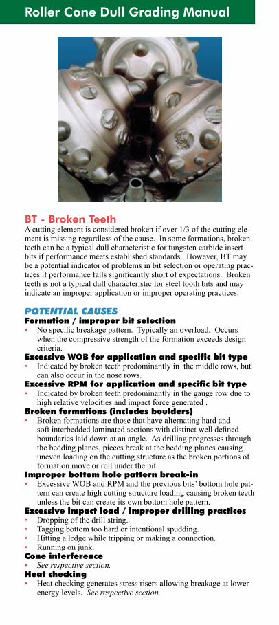
BT - Broken TeethA cutting element is considered broken if over 1/3 of the cutting ele-ment is missing regardless of the cause. In some formations, broken teeth can be a typical dull characteristic for tungsten carbide insert bits if performance meets established standards. However, BT may be a potential indicator of problems in bit selection or operating prac-ticesifperformancefallssignificantlyshortofexpectations.Brokenteeth is not a typical dull characteristic for steel tooth bits and may indicate an improper application or improper operating practices.
POTENTIAL CAUSESFormation / improper bit selection• Nospecificbreakagepattern.Typicallyanoverload.Occurs
whenthecompressivestrengthoftheformationexceedsdesigncriteria.
Excessive WOB for application and specific bit type• Indicated by broken teeth predominantly in the middle rows, but
can also occur in the nose rows.Excessive RPM for application and specific bit type• Indicated by broken teeth predominantly in the gauge row due to
high relative velocities and impact force generated .Broken formations (includes boulders)• Broken formations are those that have alternating hard and
softinterbeddedlaminatedsectionswithdistinctwelldefinedboundaries laid down at an angle. As drilling progresses through the bedding planes, pieces break at the bedding planes causing uneven loading on the cutting structure as the broken portions of formation move or roll under the bit.
Improper bottom hole pattern break-in• ExcessiveWOBandRPMandthepreviousbits’bottomholepat-
tern can create high cutting structure loading causing broken teeth unless the bit can create its own bottom hole pattern.
Excessive impact load / improper drilling practices• Dropping of the drill string.• Tagging bottom too hard or intentional spudding.• Hitting a ledge while tripping or making a connection.• Running on junk.Cone interference• See respective section.Heat checking• Heat checking generates stress risers allowing breakage at lower
energy levels. See respective section.

Smith Tool Dull Grading Manual
BROKEN TEETH - BT
Rounded gauge• Thecross-sectionisworntotheextentitisinsufficienttowith-
stand applied drilling loads. See respective section.Erosion• Cutting elements effectively become longer due to cone shell ero-
sion.Byincreasingtheeffectiveextension,thecuttingelementbecomes easier to break. See respective section.
APPLICATION RECOMMENDATIONSFormation / improper bit selection• Selectabitwithlessoffset,and/orlesstoothextension,and/or
greater tooth count, and/or tougher tooth shape.Excessive WOB for application and specific bit type• Use proper WOB for formation.• Use a shock sub when anticipating numerous formation changes.
See broken formations.• For hard formations, select a bit with less offset, and/or less tooth
extension,and/orgreatertoothcount,and/ortoughertoothshape.Excessive RPM for application and specific bit type• UseproperRPMforformation.• For hard formations, select a bit with less offset, and/or less tooth
extension,and/orgreatertoothcount,and/ortoughertoothshape.• Can also be caused by heat checking or gauge rounding. See
respective sections.Broken formations (includes boulders)• Broken teeth due to drilling broken formations can occur in any
row.ThiscanbeexcessiveWOBorRPMrelated.Anindicatorofbrokenformationsiswhenthetorquebecomesextremelyer-ratic when drilling through the boundaries, then smooths out. Use a shock sub.
Improper bottom hole pattern break-in• Bottom hole pattern break-in is considered to be when a new bit
achieves uniform cutting structure loading. This is done with lightweightsandslowRPMandisnormallyachievedwithin3to6inches.AtthatpointWOBandRPMcanbegradually increased to typical operating levels.
Excessive impact load / improper drilling practices• Follow proper drilling practices.
Roller Cone Dull Grading Manual
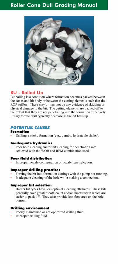
BU - Balled UpBit balling is a condition where formation becomes packed between the cones and bit body or between the cutting elements such that the ROP suffers. There may or may not be any evidence of skidding or physical damage to the bit. The cutting elements are packed off to theextentthattheyarenotpenetratingintotheformationeffectively.Rotary torque will typically decrease as the bit balls up.
POTENTIAL CAUSESFormation• Drilling a sticky formation (e.g., gumbo, hydratable shales).
Inadequate hydraulics• Poor hole cleaning and/or bit cleaning for penetration rate
achievedwiththeWOBandRPMcombinationused.
Poor fluid distribution• Impropernozzleconfigurationornozzletypeselection.
Improper drilling practices• Forcing the bit into formation cuttings with the pump not running.• Inadequate cleaning of the hole while making a connection.
Improper bit selection• Harder bit types have less optimal cleaning attributes. These bits
generally have greater tooth count and/or shorter teeth which are easiertopackoff.Theyalsoprovidelessflowareaontheholebottom.
Drilling environment• Poorlymaintainedornotoptimizeddrillingfluid.• Improperdrillingfluid.
Smith Tool Dull Grading Manual
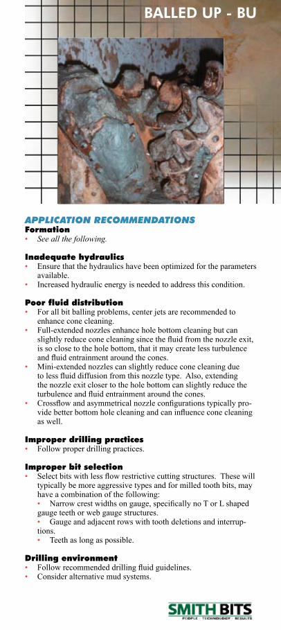
APPLICATION RECOMMENDATIONSFormation• See all the following.
Inadequate hydraulics• Ensure that the hydraulics have been optimized for the parameters
available.• Increased hydraulic energy is needed to address this condition.
Poor fluid distribution• For all bit balling problems, center jets are recommended to
enhance cone cleaning.• Full-extendednozzlesenhanceholebottomcleaningbutcan
slightlyreduceconecleaningsincethefluidfromthenozzleexit,is so close to the hole bottom, that it may create less turbulence andfluidentrainmentaroundthecones.
• Mini-extendednozzlescanslightlyreduceconecleaningduetolessfluiddiffusionfromthisnozzletype.Also,extendingthenozzleexitclosertotheholebottomcanslightlyreducetheturbulenceandfluidentrainmentaroundthecones.
• Crossflowandasymmetricalnozzleconfigurationstypicallypro-videbetterbottomholecleaningandcaninfluenceconecleaningas well.
Improper drilling practices• Follow proper drilling practices.
Improper bit selection • Selectbitswithlessflowrestrictivecuttingstructures.Thesewill
typically be more aggressive types and for milled tooth bits, may have a combination of the following:
• Narrowcrestwidthsongauge,specificallynoTorLshaped gauge teeth or web gauge structures.
• Gauge and adjacent rows with tooth deletions and interrup-tions.
• Teeth as long as possible.
Drilling environment• Followrecommendeddrillingfluidguidelines.• Consider alternative mud systems.
BALLED UP - BU
Roller Cone Dull Grading Manual
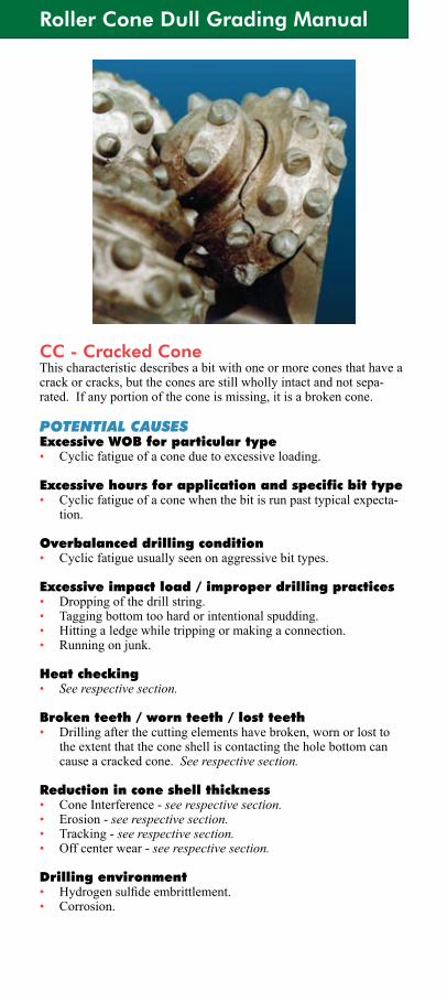
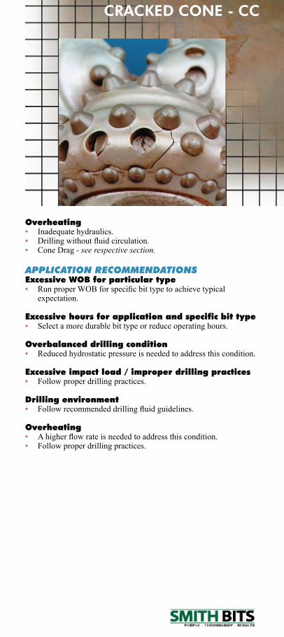
CC - Cracked ConeThis characteristic describes a bit with one or more cones that have a crack or cracks, but the cones are still wholly intact and not sepa-rated. If any portion of the cone is missing, it is a broken cone.
POTENTIAL CAUSESExcessive WOB for particular type• Cyclicfatigueofaconeduetoexcessiveloading.
Excessive hours for application and specific bit type• Cyclicfatigueofaconewhenthebitisrunpasttypicalexpecta-
tion.
Overbalanced drilling condition• Cyclic fatigue usually seen on aggressive bit types.
Excessive impact load / improper drilling practices• Dropping of the drill string.• Tagging bottom too hard or intentional spudding.• Hitting a ledge while tripping or making a connection.• Running on junk.
Heat checking• See respective section.
Broken teeth / worn teeth / lost teeth• Drilling after the cutting elements have broken, worn or lost to
theextentthattheconeshelliscontactingtheholebottomcancause a cracked cone. See respective section.
Reduction in cone shell thickness• Cone Interference - see respective section.• Erosion - see respective section.• Tracking - see respective section.• Off center wear - see respective section.
Drilling environment• Hydrogensulfideembrittlement.• Corrosion.
Smith Tool Dull Grading Manual
Overheating• Inadequate hydraulics.• Drillingwithoutfluidcirculation.• Cone Drag - see respective section.
APPLICATION RECOMMENDATIONSExcessive WOB for particular type• RunproperWOBforspecificbittypetoachievetypical
expectation.
Excessive hours for application and specific bit type• Select a more durable bit type or reduce operating hours.
Overbalanced drilling condition• Reduced hydrostatic pressure is needed to address this condition.
Excessive impact load / improper drilling practices• Follow proper drilling practices.
Drilling environment• Followrecommendeddrillingfluidguidelines.
Overheating• Ahigherflowrateisneededtoaddressthiscondition.• Follow proper drilling practices.
CRACKED CONE - CC
Roller Cone Dull Grading Manual
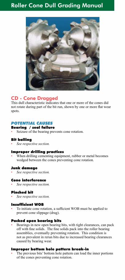
CD - Cone DraggedThis dull characteristic indicates that one or more of the cones did notrotateduringpartofthebitrun,shownbyoneormoreflatwearspots.
POTENTIAL CAUSESBearing / seal failure• Seizure of the bearing prevents cone rotation.
Bit balling• See respective section.
Improper drilling practices• When drilling cementing equipment, rubber or metal becomes
wedged between the cones preventing cone rotation.
Junk damage• See respective section.
Cone interference• See respective section.
Pinched bit• See respective section.
Insufficient WOB• Toinitiateconerotation,asufficientWOBmustbeappliedto
prevent cone slippage (drag).
Packed open bearing bits• Bearings in new open bearing bits, with tight clearances, can pack
offwithfinesolids.Thefinesolidspackintotherollerbearingassemblies, eventually preventing rotation. This condition is not as prevalent in rerun bits due to increased bearing clearances caused by bearing wear.
Improper bottom hole pattern break-in• Thepreviousbits’bottomholepatterncanloadtheinnerportions
of the cones preventing cone rotation.
Smith Tool Dull Grading Manual
APPLICATION RECOMMENDATIONSBearing / seal failure• In some applications a bearing / seal failure may not indicate a
bit related problem if performance meets established standards. However, bearing / seal failures may be a potential indicator of problems in bit selection or operating practices if performance fallssignificantlyshortofexpectations.
• Select bits and/or features with a capacity for greater total revolutions.
Improper drilling practices• Follow recommended procedures for drilling out cementing
equipment. Technical papers available from Smith Bits.
Insufficient WOB• Basedonfieldexperience,aminimumof500lb./in.ofbitdiam-
eterissufficienttoensureconerotationinmostapplications.
Packed open bearing bits• Adequatehydraulicsarenecessarytohelppreventfinesfrom
entering bearing assemblies.• Clean and regrease bit between runs.• Followrecommendeddrillingfluidguidelinestoreducefines.
Improper bottom hole pattern break-in• Proper bottom hole pattern break-in is considered to be when a
new bit achieves uniform cutting structure loading. This is done withlightweightsandslowRPMandisnormallyachievedwithin3to6inches.Atthatpoint,WOBandRPMcanbegradually increased to typical operating levels.
CONE DRAGGED - CD
Roller Cone Dull Grading Manual
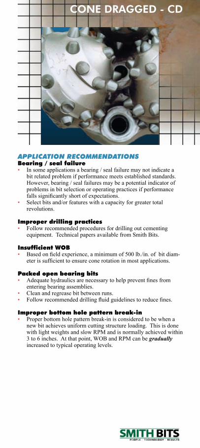
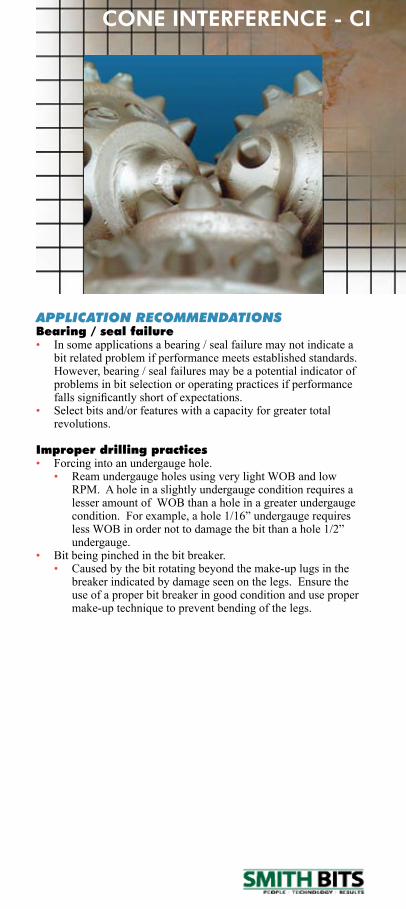
CI - Cone InterferenceA condition where the cutting structure of at least one cone has impacted upon at least one of the adjacent cones. This contact can range from a singular cutting element indentation to a groove. A bearing /seal failure may or may not have occurred.
POTENTIAL CAUSESBearing / seal failure• Enough bearing wear to allow the cones to contact one another.
Pinched bit• See respective section.
Improper drilling practices• Forcing into an undergauge hole. • Improper reaming. • Bit being forced into a less than nominal size hole. • Roller cone bit being forced into a section of hole drilled by
fixed cutterbits,duetodifferentAPIO.D.tolerances.• Bit being pinched in the bit breaker.• Bit being forced into an undersized blowout preventer stack.• Forcing a bit through casing that does not drift to the bit size
used.
Smith Tool Dull Grading Manual
APPLICATION RECOMMENDATIONSBearing / seal failure• In some applications a bearing / seal failure may not indicate a
bit related problem if performance meets established standards. However, bearing / seal failures may be a potential indicator of problems in bit selection or operating practices if performance fallssignificantlyshortofexpectations.
• Select bits and/or features with a capacity for greater total revolutions.
Improper drilling practices• Forcing into an undergauge hole. • Ream undergauge holes using very light WOB and low
RPM.Aholeinaslightlyundergaugeconditionrequiresalesser amount of WOB than a hole in a greater undergauge condition.Forexample,ahole1/16”undergaugerequireslessWOBinordernottodamagethebitthanahole1/2”undergauge.
• Bit being pinched in the bit breaker. • Caused by the bit rotating beyond the make-up lugs in the
breaker indicated by damage seen on the legs. Ensure the use of a proper bit breaker in good condition and use proper make-up technique to prevent bending of the legs.
CONE INTERFERENCE - CI
Roller Cone Dull Grading Manual
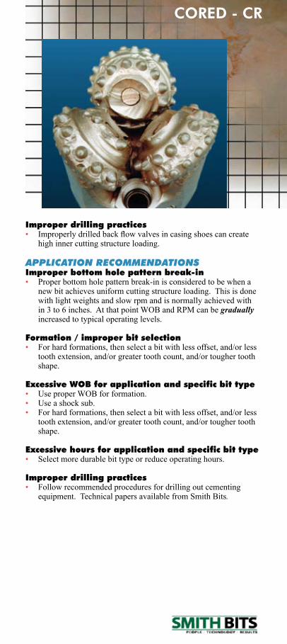
CR - Cored A bit is cored / coring when its centermost cutting elements are bro-ken,wornand/orlosttotheextentthatthenoseareaofaconeshellorconeshellsisshowingsignificantwearfromtheformation.Ifanyevidence of a fracture surface is seen, then broken cone (BC) is the cutting structure dull characteristic.
POTENTIAL CAUSESImproper bottom hole pattern break-in• ExcessiveWOBandRPMandthepreviousbits’bottomholepat-
tern can create high cutting structure loading causing broken teeth unlessthebitcancreateitsownbottomholepattern.Milltoothbitsmayexperiencespearpointbreakage.
Junk damage• Breakage of cutting structure due to running on junk whether
externalorfromthebititself.See respective section.
Erosion• Erosion causing loss of cutting structure. See respective section.
Formation / improper bit selection• Abrasivenessofformationexceedsthewearresistanceofthenose
cutting elements.• Formation too hard for bit type selected resulting in breakage of
the nose cutting elements.
Excessive WOB for application and specific bit type• Indicated by broken teeth predominantly in middle rows but can
also occur in the nose rows.
Excessive hours for application and specific bit type• Indicated by broken, worn and/or lost cutting elements when
exceedingtypicalexpectations.
Off center wear• Reduces cone support of the nose cutting elements leading to loss
of these cutting elements. See respective section.
Smith Tool Dull Grading Manual
CORED - CR
Improper drilling practices• Improperlydrilledbackflowvalvesincasingshoescancreate
high inner cutting structure loading.
APPLICATION RECOMMENDATIONSImproper bottom hole pattern break-in• Proper bottom hole pattern break-in is considered to be when a
new bit achieves uniform cutting structure loading. This is done with light weights and slow rpm and is normally achieved with in3to6inches.AtthatpointWOBandRPMcanbegradually increased to typical operating levels.
Formation / improper bit selection• For hard formations, then select a bit with less offset, and/or less
toothextension,and/orgreatertoothcount,and/ortoughertoothshape.
Excessive WOB for application and specific bit type• Use proper WOB for formation.• Use a shock sub.• For hard formations, then select a bit with less offset, and/or less
toothextension,and/orgreatertoothcount,and/ortoughertoothshape.
Excessive hours for application and specific bit type• Select more durable bit type or reduce operating hours.
Improper drilling practices• Follow recommended procedures for drilling out cementing
equipment. Technical papers available from Smith Bits.
Roller Cone Dull Grading Manual
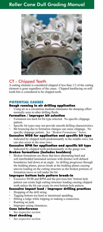
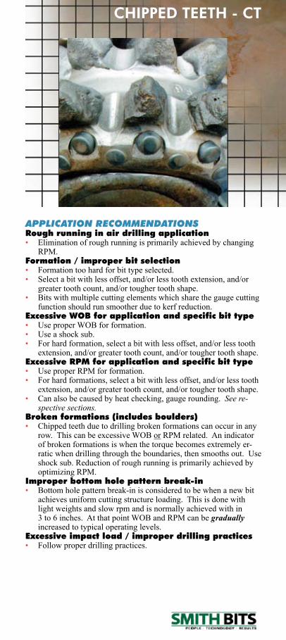
CT - Chipped TeethA cutting element is considered chipped if less than 1/3 of the cutting element is gone regardless of the cause. Chipped hardfacing on mill tooth bits is considered to be chipped teeth.
POTENTIAL CAUSESRough running in air drilling application• Using air as a circulation medium eliminates the damping effect
normallyseeninotherdrillingfluids.Formation / improper bit selection • Formationtoohardforbittypeselected.Nospecificchippage
pattern.• Specificbittypesmaynotprovidesmoothdrillingcharacteristics.• Bit bouncing due to formation changes can cause chippage. No
specificchippagepattern.See “Broken Formations” below.Excessive WOB for application and specific bit type• Indicated by chipped teeth predominantly in the middle rows, but
can also occur in the nose rows.Excessive RPM for application and specific bit type• Indicated by chipped teeth predominantly in the gauge row.Broken formations (includes boulders)• Broken formations are those that have alternating hard and
softinterbeddedlaminatedsectionswithdistinctwelldefinedboundaries laid down at an angle. As drilling progresses through the bedding planes, pieces break at the bedding planes causing uneven loading on the cutting structure as the broken portions of formation move or roll under the bit.
Improper bottom hole pattern break-in• ExcessiveWOBandRPMandthepreviousbits’bottomhole
pattern can create high cutting structure loading causing chipped teeth unless the bit can create its own bottom hole pattern.
Excessive impact load / improper drilling practices• Dropping of the drill string.• Tagging bottom too hard or intentional spudding.• Hitting a ledge while tripping or making a connection.• Running on junk.• Improper casing clearances.Cone interference• See respective section.Heat checking• See respective section.
Smith Tool Dull Grading Manual
CHIPPED TEETH - CT
APPLICATION RECOMMENDATIONSRough running in air drilling application• Elimination of rough running is primarily achieved by changing
RPM.Formation / improper bit selection• Formation too hard for bit type selected.• Selectabitwithlessoffset,and/orlesstoothextension,and/or
greater tooth count, and/or tougher tooth shape.• Bits with multiple cutting elements which share the gauge cutting
function should run smoother due to kerf reduction.Excessive WOB for application and specific bit type• Use proper WOB for formation.• Use a shock sub.• For hard formation, select a bit with less offset, and/or less tooth
extension,and/orgreatertoothcount,and/ortoughertoothshape.Excessive RPM for application and specific bit type• UseproperRPMforformation.• For hard formations, select a bit with less offset, and/or less tooth
extension,and/orgreatertoothcount,and/ortoughertoothshape.• Can also be caused by heat checking, gauge rounding. See re-
spective sections.Broken formations (includes boulders)• Chipped teeth due to drilling broken formations can occur in any
row.ThiscanbeexcessiveWOBorRPMrelated.Anindicatorofbrokenformationsiswhenthetorquebecomesextremelyer-ratic when drilling through the boundaries, then smooths out. Use shock sub. Reduction of rough running is primarily achieved by optimizingRPM.
Improper bottom hole pattern break-in• Bottom hole pattern break-in is considered to be when a new bit
achieves uniform cutting structure loading. This is done with light weights and slow rpm and is normally achieved with in 3to6inches.AtthatpointWOBandRPMcanbegradually increased to typical operating levels.
Excessive impact load / improper drilling practices• Follow proper drilling practices.
Roller Cone Dull Grading Manual
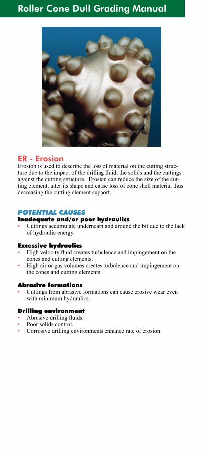
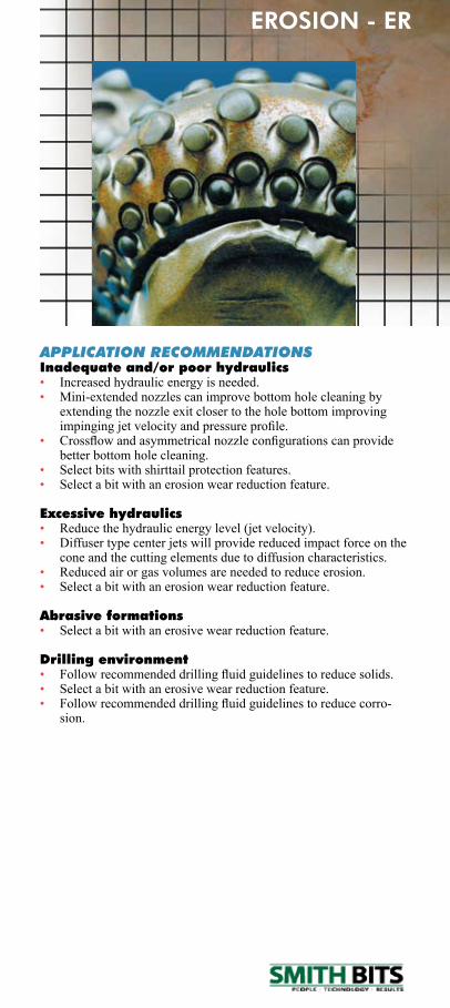
ER - ErosionErosion is used to describe the loss of material on the cutting struc-tureduetotheimpactofthedrillingfluid,thesolidsandthecuttingsagainst the cutting structure. Erosion can reduce the size of the cut-ting element, alter its shape and cause loss of cone shell material thus decreasing the cutting element support.
POTENTIAL CAUSESInadequate and/or poor hydraulics• Cuttings accumulate underneath and around the bit due to the lack
of hydraulic energy.
Excessive hydraulics• Highvelocityfluidcreatesturbulenceandimpingementonthe
cones and cutting elements.• High air or gas volumes creates turbulence and impingement on
the cones and cutting elements.
Abrasive formations• Cuttings from abrasive formations can cause erosive wear even
with minimum hydraulics.
Drilling environment• Abrasivedrillingfluids.• Poor solids control.• Corrosive drilling environments enhance rate of erosion.
Smith Tool Dull Grading Manual
APPLICATION RECOMMENDATIONSInadequate and/or poor hydraulics• Increased hydraulic energy is needed.• Mini-extendednozzlescanimprovebottomholecleaningby
extendingthenozzleexitclosertotheholebottomimprovingimpingingjetvelocityandpressureprofile.
• Crossflowandasymmetricalnozzleconfigurationscanprovidebetter bottom hole cleaning.
• Select bits with shirttail protection features.• Select a bit with an erosion wear reduction feature.
Excessive hydraulics• Reduce the hydraulic energy level (jet velocity).• Diffuser type center jets will provide reduced impact force on the
cone and the cutting elements due to diffusion characteristics.• Reduced air or gas volumes are needed to reduce erosion.• Select a bit with an erosion wear reduction feature.
Abrasive formations• Select a bit with an erosive wear reduction feature.
Drilling environment• Followrecommendeddrillingfluidguidelinestoreducesolids.• Select a bit with an erosive wear reduction feature.• Followrecommendeddrillingfluidguidelinestoreducecorro-
sion.
EROSION - ER

Roller Cone Dull Grading Manual
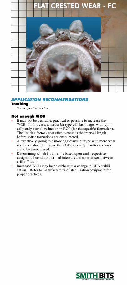
FC - Flat Crested WearFlat crested wear is an even reduction in height on a cutting element. Thewornsurfaceswillbe‘flat’andhavelittleornoradiiatthetoothflanks.Flatcrestedweardoesnothavetooccurontheentirecuttingstructure. Wear modes will vary from row to row and from cone to cone. By design, scraping can be a desirable cutting action, with the resultbeingflatcrestedwear.Thismaybethedesirableortypicaldull characteristic. It is not a concern unless performance falls short ofexpectations.Ifso,selectamoreaggressivebittypeand/oronewith a self sharpening feature.
POTENTIAL CAUSESTracking• Trackingofthe“driverows”willcausetheinnerrowstoskid.
Not enough WOB• In harder formations, the bit is not able to effectively drill the
rock.Thebitthereforetriesto‘abrade’awaytheformation.• LightWOBandhighRPMisonedrillingpracticeusedtocontrol
deviation.
Smith Tool Dull Grading Manual
APPLICATION RECOMMENDATIONSTracking• See respective section.
Not enough WOB• It may not be desirable, practical or possible to increase the
WOB. In this case, a harder bit type will last longer with typi-callyonlyasmallreductioninROP(forthatspecificformation).The limiting factor / cost effectiveness is the interval length before softer formations are encountered.
• Alternatively, going to a more aggressive bit type with more wear resistance should improve the ROP especially if softer sections are to be encountered.
• Determining which bit to run is based upon each respective design, dull condition, drilled intervals and comparison between drill-off tests.
• Increased WOB may be possible with a change in BHA stabili-zation.Refertomanufacturer’sofstabilizationequipmentforproper practices.
FLAT CRESTED WEAR - FC
Roller Cone Dull Grading Manual
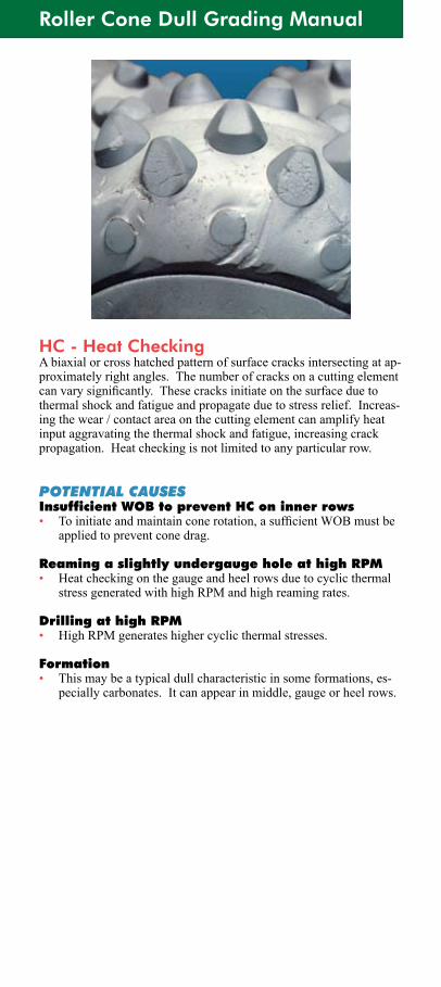
HC - Heat CheckingAbiaxialorcrosshatchedpatternofsurfacecracksintersectingatap-proximatelyrightangles.Thenumberofcracksonacuttingelementcanvarysignificantly.Thesecracksinitiateonthesurfaceduetothermal shock and fatigue and propagate due to stress relief. Increas-ing the wear / contact area on the cutting element can amplify heat input aggravating the thermal shock and fatigue, increasing crack propagation. Heat checking is not limited to any particular row.
POTENTIAL CAUSESInsufficient WOB to prevent HC on inner rows• Toinitiateandmaintainconerotation,asufficientWOBmustbe
applied to prevent cone drag.
Reaming a slightly undergauge hole at high RPM• Heat checking on the gauge and heel rows due to cyclic thermal
stressgeneratedwithhighRPMandhighreamingrates.
Drilling at high RPM• HighRPMgenerateshighercyclicthermalstresses.
Formation• This may be a typical dull characteristic in some formations, es-
pecially carbonates. It can appear in middle, gauge or heel rows.

Smith Tool Dull Grading Manual
APPLICATION RECOMMENDATIONSInsufficient WOB to prevent HC on inner rows• Basedonfieldexperienceaminimumof500lb./in.ofbitdiam-
eterissufficienttoensureconerotationinmostapplications.
Reaming a slightly undergauge hole at high RPM• ReamusingverylightWOBandlowRPM.Aholeinaslightly
undergauge condition requires a lesser amount of WOB than aholeinagreaterundergaugecondition.Forexample,ahole1/16”undergaugerequireslessWOBinordertonotdamagethebitthanahole1/2”undergauge.
Drilling at high RPM• Gauge and heel structures with diamond enhanced cutting ele-
ments can prevent heat checking and resultant breakage / chip-page in many applications.
Formation• Gauge and heel structures with diamond enhanced cutting ele-
ments can prevent heat checking and resultant breakage / chip-page in many applications.
HEAT CHECKING - HC
Roller Cone Dull Grading Manual
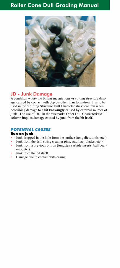
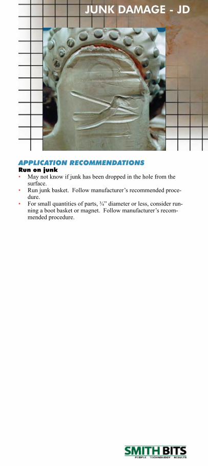
JD - Junk DamageA condition where the bit has indentations or cutting structure dam-age caused by contact with objects other than formation. It is to be usedinthe“CuttingStructureDullCharacteristics”columnwhendescribing damage to a bit knowinglycausedbyexternalsourcesofjunk.Theuseof‘JD’inthe“RemarksOtherDullCharacteristic”column implies damage caused by junk from the bit itself.
POTENTIAL CAUSESRun on junk• Junk dropped in the hole from the surface (tong dies, tools, etc.).• Junk from the drill string (reamer pins, stabilizer blades, etc.).• Junk from a previous bit run (tungsten carbide inserts, ball bear-
ings, etc.).• Junk from the bit itself.• Damage due to contact with casing.
Smith Tool Dull Grading Manual
JUNK DAMAGE - JD
APPLICATION RECOMMENDATIONSRun on junk• Maynotknowifjunkhasbeendroppedintheholefromthe
surface.• Runjunkbasket.Followmanufacturer’srecommendedproce-
dure.• Forsmallquantitiesofparts,¾”diameterorless,considerrun-
ningabootbasketormagnet.Followmanufacturer’srecom-mended procedure.
Roller Cone Dull Grading Manual
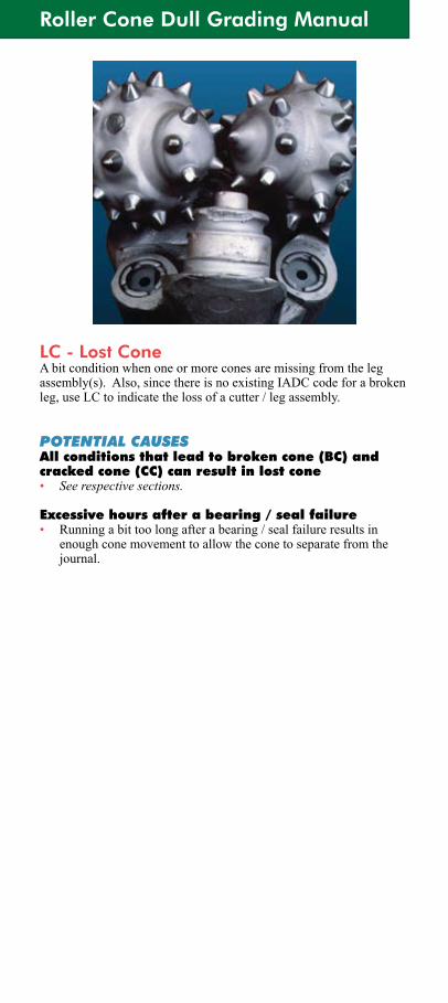
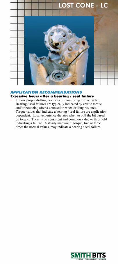
LC - Lost ConeA bit condition when one or more cones are missing from the leg assembly(s).Also,sincethereisnoexistingIADCcodeforabrokenleg,useLCtoindicatethelossofacutter/legassembly.
POTENTIAL CAUSESAll conditions that lead to broken cone (BC) and cracked cone (CC) can result in lost cone• See respective sections.
Excessive hours after a bearing / seal failure• Running a bit too long after a bearing / seal failure results in
enough cone movement to allow the cone to separate from the journal.
Smith Tool Dull Grading Manual
APPLICATION RECOMMENDATIONSExcessive hours after a bearing / seal failure• Follow proper drilling practices of monitoring torque on bit.
Bearing / seal failures are typically indicated by erratic torque and/or bouncing after a connection when drilling resumes. Torque values that indicate a bearing / seal failure are application dependent.Localexperiencedictateswhentopullthebitbasedon torque. There is no consistent and common value or threshold indicating a failure. A steady increase of torque, two or three times the normal values, may indicate a bearing / seal failure.
LOST CONE - LC
Roller Cone Dull Grading Manual
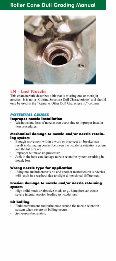
LN - Lost NozzleThis characteristic describes a bit that is missing one or more jet nozzles.Itisnota“CuttingStructureDullCharacteristic”andshouldonlybeusedinthe“RemarksOtherDullCharacteristic”column.
POTENTIAL CAUSESImproper nozzle installation• Washouts and loss of nozzles can occur due to improper installa-
tion procedures.
Mechanical damage to nozzle and/or nozzle retain-ing system• Enough movement within a worn or incorrect bit breaker can
result in damaging contact between the nozzle or retention system and the bit breaker.
• Improper bit make-up procedure.• Junk in the hole can damage nozzle retention system resulting in
nozzle loss.
Wrong nozzle type for application• Usingonemanufacturer’sbitandanothermanufacturer’snozzles
will result in a washout due to slight dimensional differences.
Erosion damage to nozzle and/or nozzle retaining system• High solid muds or abrasive muds (e.g., hematite) can cause
severe internal erosion leading to nozzle loss.
Bit balling• Fluid entrainment and turbulence around the nozzle retention
system when severe bit balling occurs.• See respective section.
Smith Tool Dull Grading Manual
LOST NOZZLE - LN
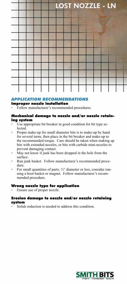
APPLICATION RECOMMENDATIONSImproper nozzle installation• Followmanufacturer’srecommendedprocedures.
Mechanical damage to nozzle and/or nozzle retain-ing system• Use appropriate bit breaker in good condition for bit type se-
lected.• Proper make-up for small diameter bits is to make-up by hand
for several turns, then place in the bit breaker and make-up to the recommended torque. Care should be taken when making up bitswithextendednozzles,orbitswithcarbidemini-nozzlestoprevent damaging contact.
• Maynotknowifjunkhasbeendroppedintheholefromthesurface.
• Runjunkbasket.Followmanufacturer’srecommendedproce-dure.
• Forsmallquantitiesofparts,¾”diameterorless,considerrun-ningabootbasketormagnet.Followmanufacturer’srecom-mended procedure.
Wrong nozzle type for application• Ensure use of proper nozzle.
Erosion damage to nozzle and/or nozzle retaining system• Solids reduction is needed to address this condition.
Roller Cone Dull Grading Manual
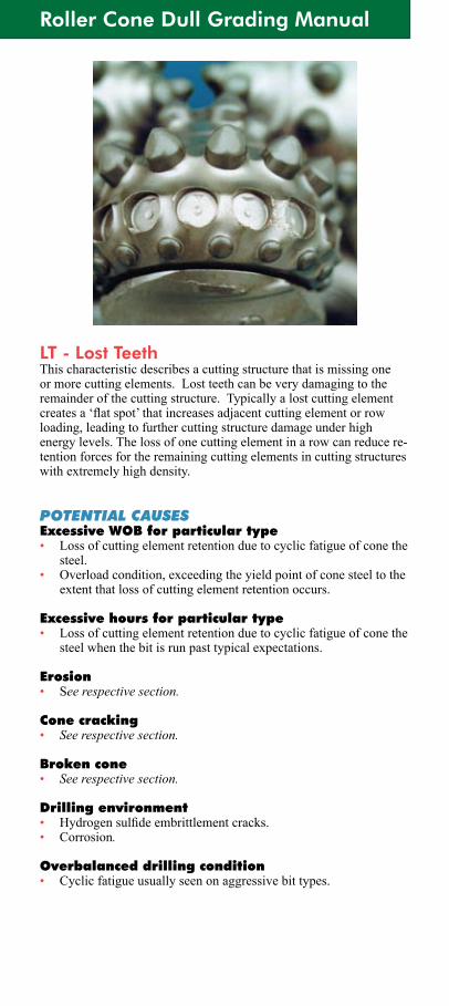
LT - Lost TeethThis characteristic describes a cutting structure that is missing one ormorecuttingelements.Lostteethcanbeverydamagingtotheremainder of the cutting structure. Typically a lost cutting element createsa‘flatspot’thatincreasesadjacentcuttingelementorrowloading, leading to further cutting structure damage under high energy levels. The loss of one cutting element in a row can reduce re-tention forces for the remaining cutting elements in cutting structures withextremelyhighdensity.
POTENTIAL CAUSESExcessive WOB for particular type• Lossofcuttingelementretentionduetocyclicfatigueofconethe
steel.• Overloadcondition,exceedingtheyieldpointofconesteeltothe
extentthatlossofcuttingelementretentionoccurs.
Excessive hours for particular type• Lossofcuttingelementretentionduetocyclicfatigueofconethe
steelwhenthebitisrunpasttypicalexpectations.
Erosion• See respective section.
Cone cracking• See respective section.
Broken cone• See respective section.
Drilling environment• Hydrogensulfideembrittlementcracks.• Corrosion.
Overbalanced drilling condition• Cyclic fatigue usually seen on aggressive bit types.

Smith Tool Dull Grading Manual
LOST TEETH - LT
APPLICATION RECOMMENDATIONSExcessive WOB for particular type• RunproperWOBforspecificbittypetoachieveaveragerun
hours.
Excessive hours for particular type• Reduce operating hours or select a more durable bit type.
Drilling environment• Followrecommendeddrillingfluidguidelinestoaddressthese
conditions.
Overbalanced drilling condition• Reduced hydrostatic pressure is needed to address this condition.
Roller Cone Dull Grading Manual
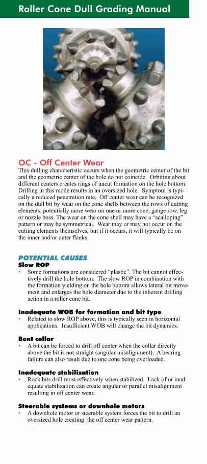
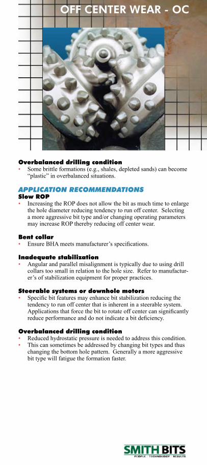
OC - Off Center WearThis dulling characteristic occurs when the geometric center of the bit and the geometric center of the hole do not coincide. Orbiting about different centers creates rings of uncut formation on the hole bottom. Drilling in this mode results in an oversized hole. Symptom is typi-cally a reduced penetration rate. Off center wear can be recognized on the dull bit by wear on the cone shells between the rows of cutting elements, potentially more wear on one or more cone, gauge row, leg ornozzleboss.Thewearontheconeshellmayhavea“scalloping”pattern or may be symmetrical. Wear may or may not occur on the cutting elements themselves, but if it occurs, it will typically be on theinnerand/orouterflanks.
POTENTIAL CAUSESSlow ROP• Someformationsareconsidered“plastic”.Thebitcannoteffec-
tively drill the hole bottom. The slow ROP in combination with the formation yielding on the hole bottom allows lateral bit move-ment and enlarges the hole diameter due to the inherent drilling action in a roller cone bit.
Inadequate WOB for formation and bit type• Related to slow ROP above, this is typically seen in horizontal
applications.InsufficientWOBwillchangethebitdynamics.
Bent collar• A bit can be forced to drill off center when the collar directly
above the bit is not straight (angular misalignment). A bearing failure can also result due to one cone being overloaded.
Inadequate stabilization• Rockbitsdrillmosteffectivelywhenstabilized.Lackoforinad-
equate stabilization can create angular or parallel misalignment resulting in off center wear.
Steerable systems or downhole motors• A downhole motor or steerable system forces the bit to drill an
oversized hole creating the off center wear pattern.
Smith Tool Dull Grading Manual
OFF CENTER WEAR - OC
Overbalanced drilling condition• Some brittle formations (e.g., shales, depleted sands) can become
“plastic”inoverbalancedsituations.
APPLICATION RECOMMENDATIONSSlow ROP• Increasing the ROP does not allow the bit as much time to enlarge
the hole diameter reducing tendency to run off center. Selecting a more aggressive bit type and/or changing operating parameters may increase ROP thereby reducing off center wear.
Bent collar• EnsureBHAmeetsmanufacturer’sspecifications.
Inadequate stabilization• Angular and parallel misalignment is typically due to using drill
collars too small in relation to the hole size. Refer to manufactur-er’sofstabilizationequipmentforproperpractices.
Steerable systems or downhole motors• Specificbitfeaturesmayenhancebitstabilizationreducingthe
tendency to run off center that is inherent in a steerable system. Applicationsthatforcethebittorotateoffcentercansignificantlyreduceperformanceanddonotindicateabitdeficiency.
Overbalanced drilling condition• Reduced hydrostatic pressure is needed to address this condition.• This can sometimes be addressed by changing bit types and thus
changing the bottom hole pattern. Generally a more aggressive bit type will fatigue the formation faster.
Roller Cone Dull Grading Manual
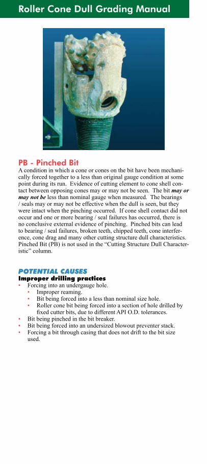
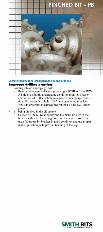
PB - Pinched BitA condition in which a cone or cones on the bit have been mechani-cally forced together to a less than original gauge condition at some point during its run. Evidence of cutting element to cone shell con-tact between opposing cones may or may not be seen. The bit may or may not be less than nominal gauge when measured. The bearings / seals may or may not be effective when the dull is seen, but they were intact when the pinching occurred. If cone shell contact did not occur and one or more bearing / seal failures has occurred, there is noconclusiveexternalevidenceofpinching.Pinchedbitscanleadto bearing / seal failures, broken teeth, chipped teeth, cone interfer-ence, cone drag and many other cutting structure dull characteristics. Pinched Bit (PB) is not used in the “Cutting Structure Dull Character-istic”column.
POTENTIAL CAUSESImproper drilling practices• Forcing into an undergauge hole. • Improper reaming. • Bit being forced into a less than nominal size hole. • Roller cone bit being forced into a section of hole drilled by
fixedcutterbits,duetodifferentAPIO.D.tolerances.• Bit being pinched in the bit breaker.• Bit being forced into an undersized blowout preventer stack.• Forcing a bit through casing that does not drift to the bit size
used.
Smith Tool Dull Grading Manual
APPLICATION RECOMMENDATIONSImproper drilling practices• Forcing into an undergauge hole. • ReamundergaugeholesusingverylightWOBandlowRPM.
A hole in a slightly undergauge condition requires a lesser amount of WOB than a hole in a greater undergauge condi-tion.Forexample,ahole1/16”undergaugerequireslessWOBinordernottodamagethebitthanahole1/2”under-gauge.
• Bit being pinched in the bit breaker. • Caused by the bit rotating beyond the make-up lugs in the
breaker indicated by damage seen on the legs. Ensure the use of a proper bit breaker in good condition and use proper make-up technique to prevent bending of the legs.
PINCHED BIT - PB
Roller Cone Dull Grading Manual
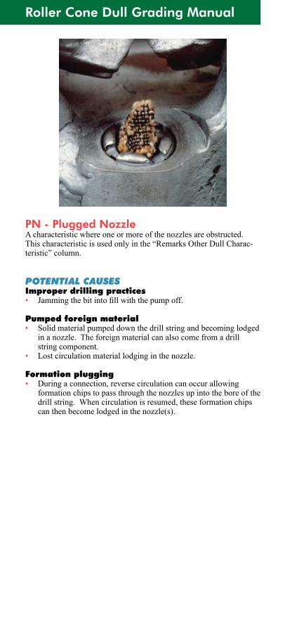
PN - Plugged NozzleA characteristic where one or more of the nozzles are obstructed. This characteristic is used only in the “Remarks Other Dull Charac-teristic”column.
POTENTIAL CAUSESImproper drilling practices• Jammingthebitintofillwiththepumpoff.
Pumped foreign material• Solid material pumped down the drill string and becoming lodged
in a nozzle. The foreign material can also come from a drill string component.
• Lostcirculationmateriallodginginthenozzle.
Formation plugging• During a connection, reverse circulation can occur allowing
formation chips to pass through the nozzles up into the bore of the drill string. When circulation is resumed, these formation chips can then become lodged in the nozzle(s).
Smith Tool Dull Grading Manual
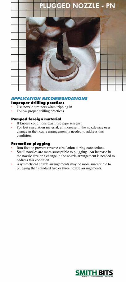
APPLICATION RECOMMENDATIONSImproper drilling practices• Use nozzle strainers when tripping in.• Follow proper drilling practices.
Pumped foreign material• Ifknownconditionsexist,usepipescreens.• For lost circulation material, an increase in the nozzle size or a
change in the nozzle arrangement is needed to address this condition.
Formation plugging• Runfloattopreventreversecirculationduringconnections.• Small nozzles are more susceptible to plugging. An increase in
the nozzle size or a change in the nozzle arrangement is needed to address this condition.
• Asymmetrical nozzle arrangements may be more susceptible to plugging than standard two or three nozzle arrangements.
PLUGGED NOZZLE - PN
Roller Cone Dull Grading Manual
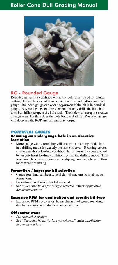
RG - Rounded GaugeRounded gauge is a condition where the outermost tip of the gauge cutting element has rounded over such that it is not cutting nominal gauge. Rounded gauge can occur regardless if the bit is in nominal gauge. A typical gauge cutting element not only drills the hole bot-tom, but drills (scrapes) the hole wall. The hole wall scraping creates alargerwearflatthandoestheholebottomdrilling.Roundedgaugewill decrease the ROP and can increase torque.
POTENTIAL CAUSESReaming an undergauge hole in an abrasive formation• Moregaugewear/roundingwilloccurinareamingmodethan
inadrillingmodeforexactlythesameinterval.Reamingcreatesa severe in-thrust loading condition that is normally counteracted by an out-thrust loading condition seen in the drilling mode. This force imbalance causes more cone slippage on the hole wall, thus more wear / rounding.
Formation / improper bit selection• Gauge rounding can be a typical dull characteristic in abrasive
formations.• Formation too abrasive for bit selected.• See “Excessive hours for bit type selected”underApplication
Recommendations.
Excessive RPM for application and specific bit type• ExcessiveRPMacceleratesthemechanismofgaugerounding
due to increases in relative surface velocities.
Off center wear• See respective section.• See “Excessive hours for bit type selected”underApplication
Recommendations.
Smith Tool Dull Grading Manual
ROUNDED GAUGE - RG
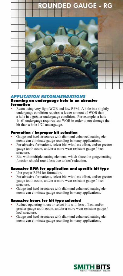
APPLICATION RECOMMENDATIONSReaming an undergauge hole in an abrasive formation• ReamusingverylightWOBandlowRPM.Aholeinaslightly
undergauge condition requires a lesser amount of WOB than aholeinagreaterundergaugecondition.Forexample,ahole1/16”undergaugerequireslessWOBinordertonotdamagethebitthanahole1/2”undergauge.
Formation / improper bit selection• Gauge and heel structures with diamond enhanced cutting ele-
ments can eliminate gauge rounding in many applications.• For abrasive formations, select bits with less offset, and/or greater
gauge tooth count, and/or a more wear resistant gauge / heel structure.
• Bits with multiple cutting elements which share the gauge cutting function should round less due to kerf reduction.
Excessive RPM for application and specific bit type• UseproperRPMforformation.• For abrasive formations, select bits with less offset, and/or greater
gauge tooth count, and/or a more wear resistant gauge / heel structure.
• Gauge and heel structures with diamond enhanced cutting ele-ments can eliminate gauge rounding in many applications.
Excessive hours for bit type selected• Reduce operating hours or select bits with less offset, and/or
greater gauge tooth count, and/or a more wear resistant gauge / heel structure.
• Gauge and heel structures with diamond enhanced cutting ele-ments can eliminate gauge rounding in many applications.
Roller Cone Dull Grading Manual
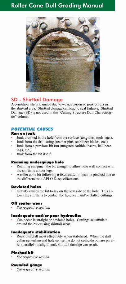
SD - Shirttail DamageA condition where damage due to wear, erosion or junk occurs in the shirttail area. Shirttail damage can lead to seal failures. Shirttail Damage (SD) is not used in the “Cutting Structure Dull Characteris-tic”column.
POTENTIAL CAUSESRun on junk• Junk dropped in the hole from the surface (tong dies, tools, etc.).• Junk from the drill string (reamer pins, stabilizer blades, etc.).• Junk from a previous bit run (tungsten carbide inserts, ball bear-
ings, etc.).• Junk from the bit itself.
Reaming undergauge hole• Reaming can pinch the bit enough to allow hole wall contact with
the shirttails and/or legs.• Arollerconebitfollowingafixedcutterbitcanbepincheddueto
thedifferencesinAPIO.D.specifications.
Deviated holes• Gravity causes the bit to lay on the low side of the hole. This al-
lows the shirttails to contact the hole wall and/or drilled cuttings.
Off center wear• See respective section.
Inadequate and/or poor hydraulics• Can occur in straight or deviated holes. Cuttings accumulate
around the bit causing shirttail wear.
Inadequate stabilization• Rock bits drill most effectively when stabilized. When the drill
collar centerline and hole centerline do not coincide but are paral-lel (parallel misalignment), shirttail damage can result.
Pinched bit• See respective section.
Rounded gauge• See respective section.
Smith Tool Dull Grading Manual
APPLICATION RECOMMENDATIONSRun on junk• Maynotknowifjunkhasbeendroppedintheholefromthe
surface.• Runjunkbasket.Followmanufacturer’srecommendedproce-
dure.• Forsmallquantitiesofparts,¾”diameterorless,considerrun-
ningabootbasketormagnet.Followmanufacturer’srecom-mended procedure.
Reaming undergauge hole • ReamusingverylightWOBandlowRPM.Aholeinaslightly
undergauge condition requires a lesser amount of WOB than aholeinagreaterundergaugecondition.Forexample,ahole1/16”undergaugerequireslessWOBinordertonotdamagethebitthanahole1/2”undergauge.
• If the life of a roller cone bit is limited due to immediate gauge wearwhenfollowingafixedcutterbit,selectabitwithamorerobust gauge structure and/or with less offset.
Deviated holes• Select bits with shirttail protection features and/or with stabiliza-
tion features.
Inadequate and/or poor hydraulics• Increased hydraulic energy is needed to address this condition.• Mini-extendednozzlescanimprovebottomholecleaningby
extendingthenozzleexitclosertotheholebottomimprovingimpingingjetvelocityandpressureprofile.
• Crossflowandasymmetricalnozzleconfigurationscanprovidebetter bottom hole cleaning.
• Select bits with shirttail protection features.
Inadequate stabilization• Select bits with stabilization features.• Parallel misalignment is typically due to using drill collars too
small in relation to the hole size. Refer to manufacturers of stabi-lization equipment for proper practices.
SHIRTTAIL DAMAGE - SD
Roller Cone Dull Grading Manual
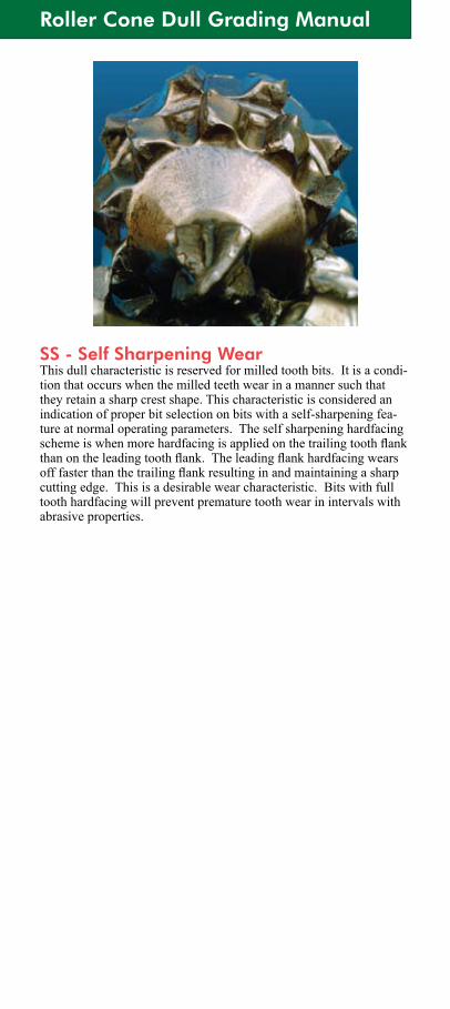
SS - Self Sharpening WearThis dull characteristic is reserved for milled tooth bits. It is a condi-tion that occurs when the milled teeth wear in a manner such that they retain a sharp crest shape. This characteristic is considered an indication of proper bit selection on bits with a self-sharpening fea-ture at normal operating parameters. The self sharpening hardfacing schemeiswhenmorehardfacingisappliedonthetrailingtoothflankthanontheleadingtoothflank.Theleadingflankhardfacingwearsofffasterthanthetrailingflankresultinginandmaintainingasharpcutting edge. This is a desirable wear characteristic. Bits with full tooth hardfacing will prevent premature tooth wear in intervals with abrasive properties.
Smith Tool Dull Grading Manual
SELF SHARPENING WEAR - SS
Roller Cone Dull Grading Manual
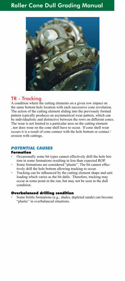
TR - TrackingA condition where the cutting elements on a given row impact on the same bottom hole location with each successive cone revolution. The action of the cutting element sliding into the previously formed pattern typically produces an asymmetrical wear pattern, which can be individualistic and distinctive between the rows on different cones. The wear is not limited to a particular area on the cutting element , nor does wear on the cone shell have to occur. If cone shell wear occurs it is a result of cone contact with the hole bottom or contact / erosion with cuttings.
POTENTIAL CAUSESFormation• Occasionally some bit types cannot effectively drill the hole bot-
tominsomeformationsresultinginlessthanexpectedROP.• Someformationsareconsidered“plastic”.Thebitcannoteffec-
tively drill the hole bottom allowing tracking to occur. • Trackingcanbeinfluencedbythecuttingelementshapeandunit
loading which varies as the bit dulls. Therefore, tracking may occur at some point in the run, but may not be seen in the dull condition.
Overbalanced drilling condition• Some brittle formations (e.g., shales, depleted sands) can become
“plastic”inoverbalancedsituations.
Smith Tool Dull Grading Manual
APPLICATION RECOMMENDATIONSFormation• Selecting a different bit type and/or changing operating param-
eters may reduce tracking thereby increasing ROP.
Overbalanced drilling condition• Reduced hydrostatic pressure is needed to address this condition.• This can sometimes be addressed by changing bit types (generally
more aggressive) and thus changing the bottom hole pattern.
TRACKING - TR
Roller Cone Dull Grading Manual
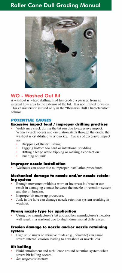
WO - Washed Out BitAwashoutiswheredrillingfluidhaserodedapassagefromaninternalflowareatotheexteriorofthebit.Itisnotlimitedtowelds.Thischaracteristicisusedonlyinthe“RemarksDullCharacteristic”column.
POTENTIAL CAUSESExcessive impact load / improper drilling practices• Weldsmaycrackduringthebitrunduetoexcessiveimpact.
When a crack occurs and circulation starts through the crack, the washoutisestablishedveryquickly.Causesofexcessiveimpactare:
• Dropping of the drill string. • Tagging bottom too hard or intentional spudding. • Hitting a ledge while tripping or making a connection. • Running on junk.
Improper nozzle installation• Washouts can occur due to improper installation procedures.
Mechanical damage to nozzle and/or nozzle retain-ing system• Enough movement within a worn or incorrect bit breaker can
result in damaging contact between the nozzle or retention system and the bit breaker.
• Improper bit make-up procedure.• Junk in the hole can damage nozzle retention system resulting in
washout.
Wrong nozzle type for application• Usingonemanufacturer’sbitandanothermanufacturer’snozzles
will result in a washout due to slight dimensional differences.
Erosion damage to nozzle and/or nozzle retaining system• High solid muds or abrasive muds (e.g., hematite) can cause
severe internal erosion leading to a washout or nozzle loss.
Bit balling• Fluid entrainment and turbulence around retention system when
severe bit balling occurs.• See respective section.
Smith Tool Dull Grading Manual
WASHED OUT BIT - WO
APPLICATION RECOMMENDATIONSExcessive impact load / improper drilling practices• Follow proper drilling practices.
Improper nozzle installation• Followmanufacturers’recommendedprocedures.
Mechanical damage to nozzle and/or nozzle retain-ing system• Use appropriate bit breaker in good condition for bit type se-
lected.• Proper make-up for small diameter bits is to make-up by hand for
several turns, then place in bit breaker and make-up to recom-mended torque. Care should be taken when making up bits with sometypeofextendednozzles,orbitswithcarbidemini-nozzlesto prevent damaging contact.
• Maynotknowifjunkhasbeendroppedintheholefromthesurface.
• Runjunkbasket.Followmanufacturer’srecommendedproce-dure.
• Forsmallquantitiesofjunk,¾”diameterorless,considerrun-ningabootbasketormagnet.Followmanufacturer’srecom-mended procedure.
Wrong nozzle type for application• Ensure use of proper nozzle.
Erosion damage to nozzle and/or nozzle retaining system• A reduction in solids or a less abrasive mud type is needed to
reduce the internal erosion leading to a washout or a nozzle loss.
Roller Cone Dull Grading Manual
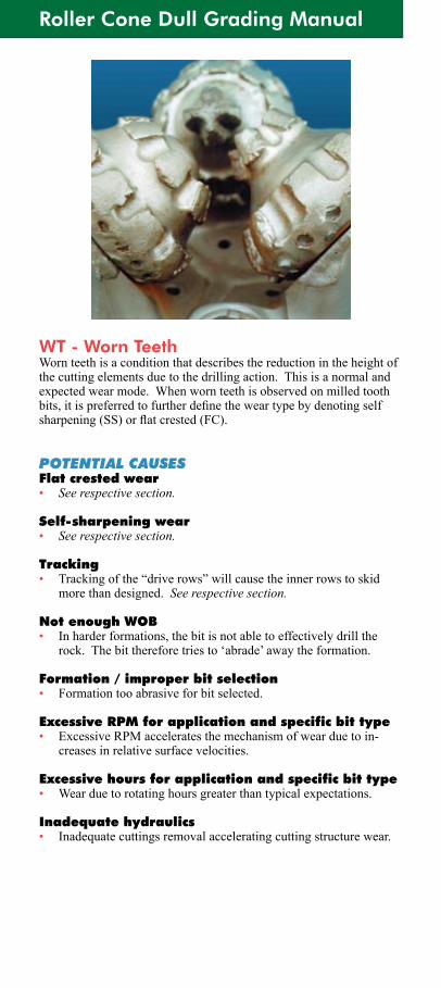
WT - Worn TeethWorn teeth is a condition that describes the reduction in the height of the cutting elements due to the drilling action. This is a normal and expectedwearmode.Whenwornteethisobservedonmilledtoothbits,itispreferredtofurtherdefinetheweartypebydenotingselfsharpening(SS)orflatcrested(FC).
POTENTIAL CAUSESFlat crested wear• See respective section.
Self-sharpening wear• See respective section.
Tracking• Trackingofthe“driverows”willcausetheinnerrowstoskid
more than designed. See respective section.
Not enough WOB• In harder formations, the bit is not able to effectively drill the
rock.Thebitthereforetriesto‘abrade’awaytheformation.
Formation / improper bit selection• Formation too abrasive for bit selected.
Excessive RPM for application and specific bit type• ExcessiveRPMacceleratesthemechanismofwearduetoin-
creases in relative surface velocities.
Excessive hours for application and specific bit type• Wearduetorotatinghoursgreaterthantypicalexpectations.
Inadequate hydraulics• Inadequate cuttings removal accelerating cutting structure wear.
Smith Tool Dull Grading Manual
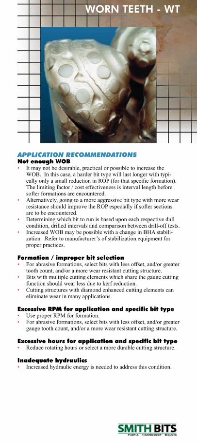
APPLICATION RECOMMENDATIONSNot enough WOB • It may not be desirable, practical or possible to increase the
WOB. In this case, a harder bit type will last longer with typi-callyonlyasmallreductioninROP(forthatspecificformation).The limiting factor / cost effectiveness is interval length before softer formations are encountered.
• Alternatively, going to a more aggressive bit type with more wear resistance should improve the ROP especially if softer sections are to be encountered.
• Determining which bit to run is based upon each respective dull condition, drilled intervals and comparison between drill-off tests.
• Increased WOB may be possible with a change in BHA stabili-zation.Refertomanufacturer’sofstabilizationequipmentforproper practices.
Formation / improper bit selection• For abrasive formations, select bits with less offset, and/or greater
tooth count, and/or a more wear resistant cutting structure.• Bits with multiple cutting elements which share the gauge cutting
function should wear less due to kerf reduction.• Cutting structures with diamond enhanced cutting elements can
eliminate wear in many applications.
Excessive RPM for application and specific bit type• UseproperRPMforformation.• For abrasive formations, select bits with less offset, and/or greater
gauge tooth count, and/or a more wear resistant cutting structure.
Excessive hours for application and specific bit type• Reduce rotating hours or select a more durable cutting structure.
Inadequate hydraulics• Increased hydraulic energy is needed to address this condition.
WORN TEETH - WT
FiXED CUTTERDULL GRADING
MANUAL
Fixed Cutter Dull Grading Manual
The Smith Bits definitions and guidelines shown within are NOT IADC standards. They were cre-ated solely for internal purposes to reduce ambi-guities and to improve our consistency in grading
dull bits within the current IADC structure.
P.O. Box 60068 • Houston, Texas 77205-0068
U.S. And Canada: 800/US SMITH • Tel. 281/443-3370
Fax: 281-233-5237 Internet: http://www.smith.com
Copyright © 2008 Smith International, Inc. All rights reserved.
ST-2067 • 25M • 01/08
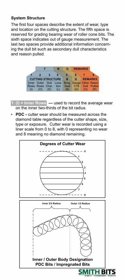
System StructureThe first four spaces describe the extent of wear, type and location on the cutting structure. The fifth space is reserved for grading bearing wear of roller cone bits. The sixth space indicates out of gauge measurement. The last two spaces provide additional information concern-ing the dull bit such as secondary dull characteristics and reason pulled.
InnerRows
(I)
OuterRows(O)
DullChar.(D)
Loca-tion(L)
Brng.Seal(B)
Gauge1/16(G)
OtherDull(O)
ReasonPulled
(R)
CUTTING STRUCTURE B G REMARKS
BT G REMARKS
1 2 3 4 5 6 7 8
1: (I) = Inner Rows — used to record the average wear on the inner two-thirds of the bit radius.
• PDC - cutter wear should be measured across the diamond table regardless of the cutter shape, size, type or exposure. Cutter wear is recorded using a liner scale from 0 to 8, with 0 representing no wear and 8 meaning no diamond remaining.
Degrees of Cutter Wear0
1
2
3
4
5
6
7
8
Inner 2/3 Radius Outer 1/3 Radius
Inner / Outer Body Designation PDC Bits / Impregnated Bits
Fixed Cutter Dull Grading Manual
Inner Radius(Pilot)
Outer Radius(Reamer)
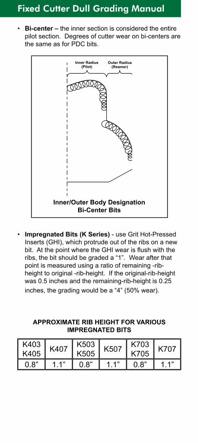
• Bi-center – the inner section is considered the entire pilot section. Degrees of cutter wear on bi-centers are the same as for PDC bits.
Inner/Outer Body Designation Bi-Center Bits
• Impregnated Bits (K Series) - use Grit Hot-Pressed Inserts (GHI), which protrude out of the ribs on a new bit. At the point where the GHI wear is flush with the ribs, the bit should be graded a “1”. Wear after that point is measured using a ratio of remaining -rib-height to original -rib-height. If the original-rib-height was 0.5 inches and the remaining-rib-height is 0.25 inches, the grading would be a “4” (50% wear).
APPROXIMATE RIB HEIGHT FOR VARIOUS IMPREGNATED BITS
K403K405 K407 K503
K505 K507 K703K705 K707
0.8” 1.1” 0.8” 1.1” 0.8” 1.1”
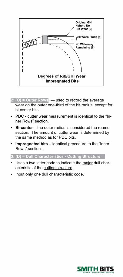
2: (O) = Outer Rows — used to record the average wear on the outer one-third of the bit radius, except for bi-center bits.
• PDC - cutter wear measurement is identical to the “In-ner Rows” section.
• Bi-center – the outer radius is considered the reamer section. The amount of cutter wear is determined by the same method as for PDC bits.
• Impregnated bits – identical procedure to the “Inner Rows” section.
Degrees of Rib/GHI Wear Impregnated Bits
Original GHIHeight, NoRib Wear (0)
No WaterwayRemaining (8)
GHI Worn Flush (1)4
3: (D) = Dull Characteristics - Cutting Structure• Uses a two letter code to indicate the major dull char-
acteristic of the cutting structure.• Input only one dull characteristic code.
Fixed Cutter Dull Grading Manual
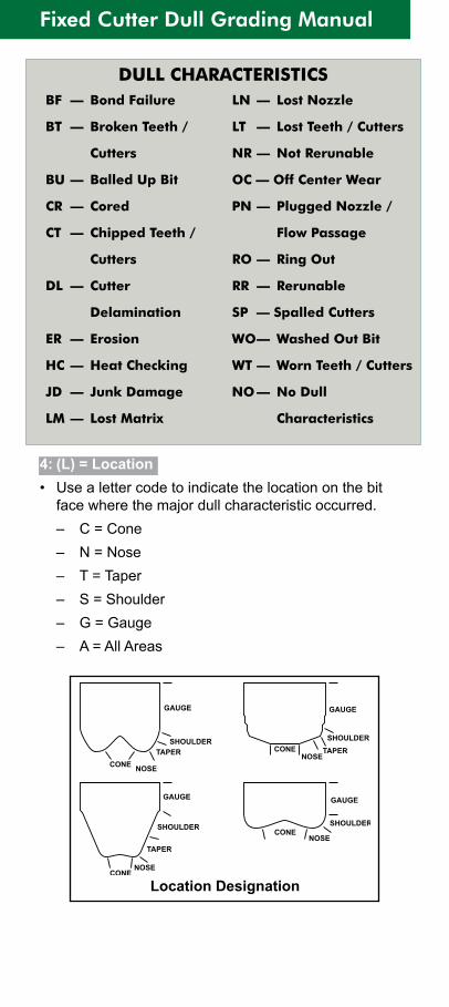
4: (L) = Location• Use a letter code to indicate the location on the bit
face where the major dull characteristic occurred. – C = Cone – N = Nose – T = Taper – S = Shoulder – G = Gauge – A = All Areas
Location Designation
GAUGE GAUGE
GAUGEGAUGE
SHOULDER SHOULDER
SHOULDERSHOULDER
TAPER TAPER
TAPER
NOSENOSE
NOSE
NOSE
CONE
CONE
CONE
CONE
DULL CHARACTERISTICS BF — Bond Failure
BT — Broken Teeth /
Cutters
BU — Balled Up Bit
CR — Cored
CT — Chipped Teeth /
Cutters
DL — Cutter
Delamination
ER — Erosion
HC — Heat Checking
JD — Junk Damage
LM — Lost Matrix
LN — Lost Nozzle
LT — Lost Teeth / Cutters
NR — Not Rerunable
OC — Off Center Wear
PN — Plugged Nozzle /
Flow Passage
RO — Ring Out
RR — Rerunable
SP — Spalled Cutters
WO — Washed Out Bit
WT — Worn Teeth / Cutters
NO — No Dull
Characteristics
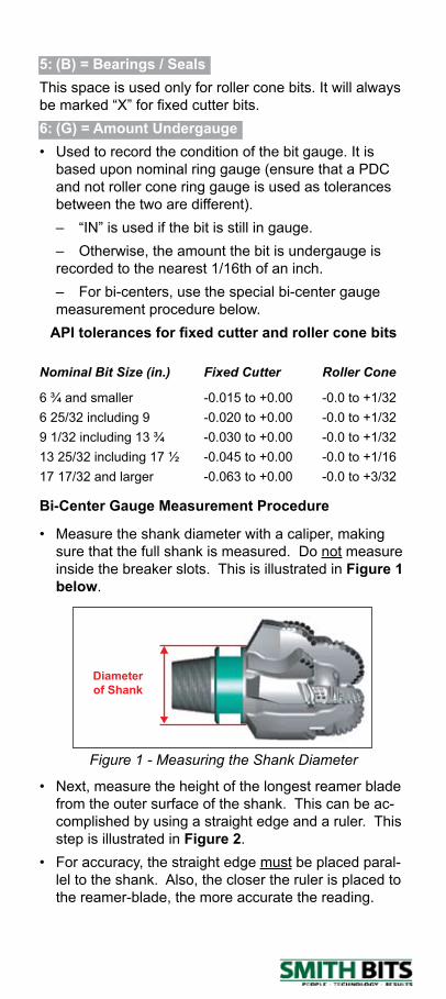
5: (B) = Bearings / SealsThis space is used only for roller cone bits. It will always be marked “X” for fixed cutter bits.6: (G) = Amount Undergauge • Used to record the condition of the bit gauge. It is
based upon nominal ring gauge (ensure that a PDC and not roller cone ring gauge is used as tolerances between the two are different).
– “IN” is used if the bit is still in gauge. – Otherwise, the amount the bit is undergauge is
recorded to the nearest 1/16th of an inch. – For bi-centers, use the special bi-center gauge
measurement procedure below.API tolerances for fixed cutter and roller cone bits
Nominal Bit Size (in.) Fixed Cutter Roller Cone
6 ¾ and smaller -0.015 to +0.00 -0.0 to +1/32 6 25/32 including 9 -0.020 to +0.00 -0.0 to +1/32 9 1/32 including 13 ¾ -0.030 to +0.00 -0.0 to +1/3213 25/32 including 17 ½ -0.045 to +0.00 -0.0 to +1/1617 17/32 and larger -0.063 to +0.00 -0.0 to +3/32
Bi-Center Gauge Measurement Procedure
• Measure the shank diameter with a caliper, making sure that the full shank is measured. Do not measure inside the breaker slots. This is illustrated in Figure 1 below.
Figure 1 - Measuring the Shank Diameter
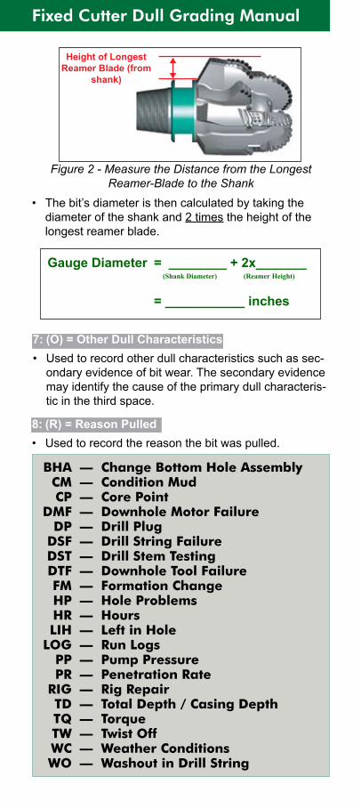
• Next, measure the height of the longest reamer blade from the outer surface of the shank. This can be ac-complished by using a straight edge and a ruler. This step is illustrated in Figure 2.
• For accuracy, the straight edge must be placed paral-lel to the shank. Also, the closer the ruler is placed to the reamer-blade, the more accurate the reading.
Diameter of Shank
Fixed Cutter Dull Grading Manual
Figure 2 - Measure the Distance from the Longest Reamer-Blade to the Shank
• The bit’s diameter is then calculated by taking the diameter of the shank and 2 times the height of the longest reamer blade.
8: (R) = Reason Pulled• Used to record the reason the bit was pulled.
Gauge Diameter = ________ + 2x_______ (Shank Diameter) (Reamer Height)
= ___________ inches
7: (O) = Other Dull Characteristics• Used to record other dull characteristics such as sec-
ondary evidence of bit wear. The secondary evidence may identify the cause of the primary dull characteris-tic in the third space.
BHA — Change Bottom Hole Assembly CM — Condition Mud CP — Core Point DMF — Downhole Motor Failure DP — Drill Plug DSF — Drill String Failure DST — Drill Stem Testing DTF — Downhole Tool Failure FM — Formation Change HP — Hole Problems HR — Hours LIH — Left in Hole LOG — Run Logs PP — Pump Pressure PR — Penetration Rate RIG — Rig Repair TD — Total Depth / Casing Depth TQ — Torque TW — Twist Off WC — Weather Conditions WO — Washout in Drill String
Height of Longest Reamer Blade (from
shank)
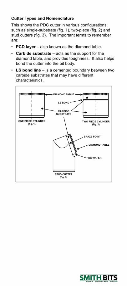
Cutter Types and NomenclatureThis shows the PDC cutter in various configurations such as single-substrate (fig. 1), two-piece (fig. 2) and stud cutters (fig. 3). The important terms to remember are:• PCD layer – also known as the diamond table.• Carbide substrate – acts as the support for the
diamond table, and provides toughness. It also helps bond the cutter into the bit body.
• LS bond line – is a cemented boundary between two carbide substrates that may have different characteristics.
STUD CUTTER(fig. 3)
TWO PIECE CYLINDER(fig. 2)
ONE PIECE CYLINDER(fig. 1)
BRAZE POINT
DIAMOND TABLE
DIAMOND TABLE
PDC WAFER
CARBIDESUBSTRATE
LS BOND
Fixed Cutter Dull Grading Manual
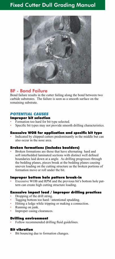
BF - Bond FailureBond failure results in the cutter failing along the bond between two carbide substrates. The failure is seen as a smooth surface on the remaining substrate.
POTENTIAL CAUSESImproper bit selection • Formation too hard for bit type selected.• Specificbittypesmaynotprovidesmoothdrillingcharacteristics.
Excessive WOB for application and specific bit type• Indicated by chipped cutters predominantly in the middle but can
also occur in the nose area.
Broken formations (includes boulders)• Broken formations are those that have alternating hard and
softinterbeddedlaminatedsectionswithdistinctwelldefinedboundaries laid down at a angle. As drilling progresses through the bedding planes, pieces break at the bedding planes causing uneven loading on the cutting structure as the broken portions of formation move or roll under the bit.
Improper bottom hole pattern break-in• ExcessiveWOBandRPMandthepreviousbit’sbottomholepat-
tern can create high cutting structure loading.
Excessive impact load / improper drilling practices• Dropping of the drill string.• Tagging bottom too hard / intentional spudding.• Hitting a ledge while tripping or making a connection.• Running on junk.• Improper casing clearances.
Drilling environment• Followrecommendeddrillingfluidguidelines.
Bit vibration• Bit bouncing due to formation changes.
BOND FAILURE - BF
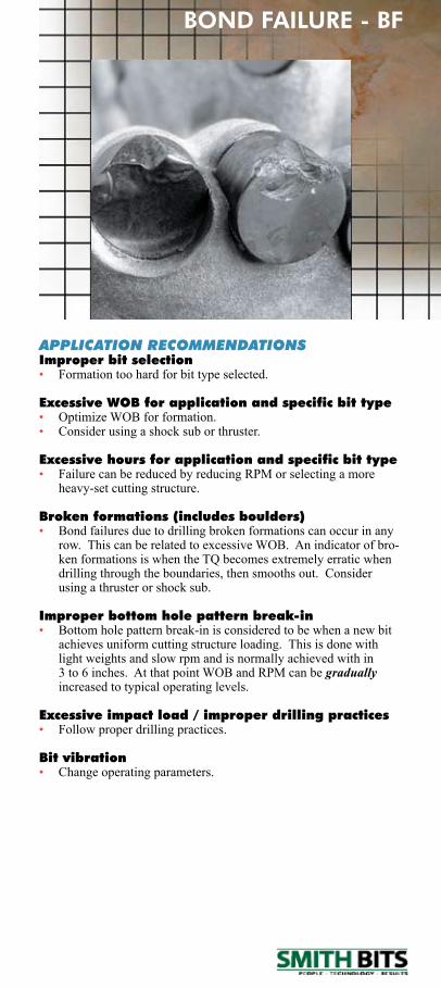
APPLICATION RECOMMENDATIONSImproper bit selection• Formation too hard for bit type selected.
Excessive WOB for application and specific bit type• Optimize WOB for formation.• Consider using a shock sub or thruster.
Excessive hours for application and specific bit type• FailurecanbereducedbyreducingRPMorselectingamore
heavy-set cutting structure.
Broken formations (includes boulders)• Bond failures due to drilling broken formations can occur in any
row.ThiscanberelatedtoexcessiveWOB.Anindicatorofbro-kenformationsiswhentheTQbecomesextremelyerraticwhendrilling through the boundaries, then smooths out. Consider using a thruster or shock sub.
Improper bottom hole pattern break-in• Bottom hole pattern break-in is considered to be when a new bit
achieves uniform cutting structure loading. This is done with light weights and slow rpm and is normally achieved with in 3to6inches.AtthatpointWOBandRPMcanbegradually increased to typical operating levels.
Excessive impact load / improper drilling practices• Follow proper drilling practices.
Bit vibration• Change operating parameters.
Fixed Cutter Dull Grading Manual
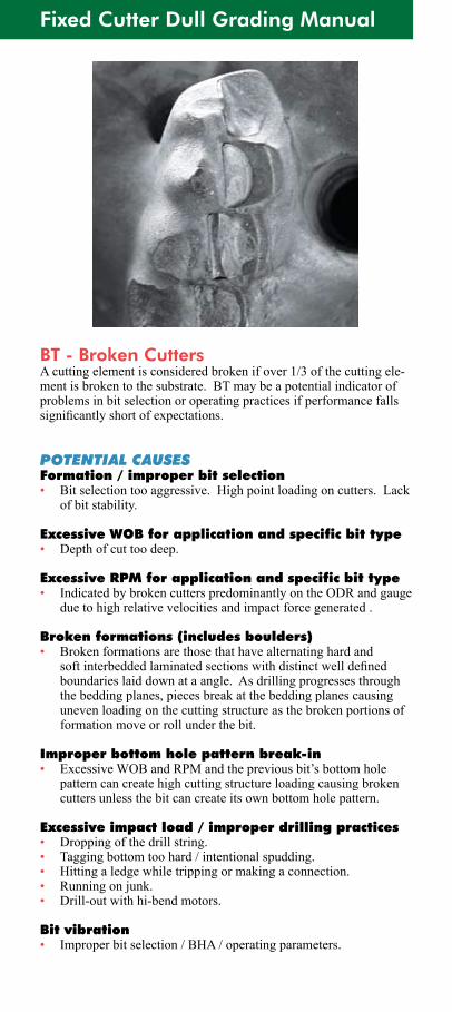
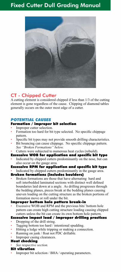
BT - Broken CuttersA cutting element is considered broken if over 1/3 of the cutting ele-ment is broken to the substrate. BT may be a potential indicator of problems in bit selection or operating practices if performance falls significantlyshortofexpectations.
POTENTIAL CAUSESFormation / improper bit selection• Bitselectiontooaggressive.Highpointloadingoncutters.Lack
of bit stability.
Excessive WOB for application and specific bit type• Depth of cut too deep.
Excessive RPM for application and specific bit type• Indicated by broken cutters predominantly on the ODR and gauge
due to high relative velocities and impact force generated .
Broken formations (includes boulders)• Broken formations are those that have alternating hard and
softinterbeddedlaminatedsectionswithdistinctwelldefinedboundaries laid down at a angle. As drilling progresses through the bedding planes, pieces break at the bedding planes causing uneven loading on the cutting structure as the broken portions of formation move or roll under the bit.
Improper bottom hole pattern break-in• ExcessiveWOBandRPMandthepreviousbit’sbottomhole
pattern can create high cutting structure loading causing broken cutters unless the bit can create its own bottom hole pattern.
Excessive impact load / improper drilling practices• Dropping of the drill string.• Tagging bottom too hard / intentional spudding.• Hitting a ledge while tripping or making a connection.• Running on junk.• Drill-out with hi-bend motors.
Bit vibration• Improper bit selection / BHA / operating parameters.
BROKEN CUTTERS - BT
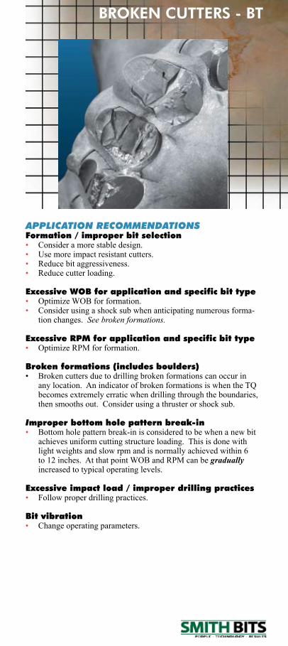
APPLICATION RECOMMENDATIONSFormation / improper bit selection• Consider a more stable design.• Use more impact resistant cutters.• Reduce bit aggressiveness.• Reduce cutter loading.
Excessive WOB for application and specific bit type• Optimize WOB for formation.• Consider using a shock sub when anticipating numerous forma-
tion changes. See broken formations.
Excessive RPM for application and specific bit type• OptimizeRPMforformation.
Broken formations (includes boulders)• Brokencuttersduetodrillingbrokenformationscanoccurin
any location. An indicator of broken formations is when the TQ becomesextremelyerraticwhendrillingthroughtheboundaries,then smooths out. Consider using a thruster or shock sub.
Improper bottom hole pattern break-in• Bottom hole pattern break-in is considered to be when a new bit
achieves uniform cutting structure loading. This is done with light weights and slow rpm and is normally achieved within 6 to12inches.AtthatpointWOBandRPMcanbegradually increased to typical operating levels.
Excessive impact load / improper drilling practices• Follow proper drilling practices.
Bit vibration• Change operating parameters.
Fixed Cutter Dull Grading Manual
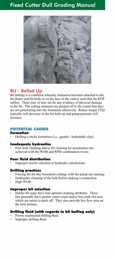
BU - Balled UpBit balling is a condition whereby formation becomes attached to the bit blades and bit body or on the face of the cutters such that the ROP suffers. There may or may not be any evidence of physical damage tothebit.Thecuttingelementsarepackedofftotheextentthattheyare not penetrating into the formation effectively. Rotary torque (TQ) typically will decrease as the bit balls up and pump pressure will increase.
POTENTIAL CAUSESFormation• Drilling a sticky formation (i.e., gumbo - hydratable clay).
Inadequate hydraulics• Poor hole cleaning and/or bit cleaning for penetration rate
achievedwiththeWOBandRPMcombinationinuse.
Poor fluid distribution• Improper nozzle selection or hydraulic calculations.
Drilling practices• Forcing the bit into formation cuttings with the pump not running.• Inadequate cleaning of the hole before making a connection.• High WOB.
Improper bit selection• Harder bit types have less optimal cleaning attributes. These
bits generally have greater cutter count and/or less junk slot area whichareeasiertopackoff.Theyalsoprovidelessflowareaonthe hole bottom.
Drilling fluid (with regards to bit balling only)• Poorlymaintaineddrillingfluid.• Improperdrillingfluid.
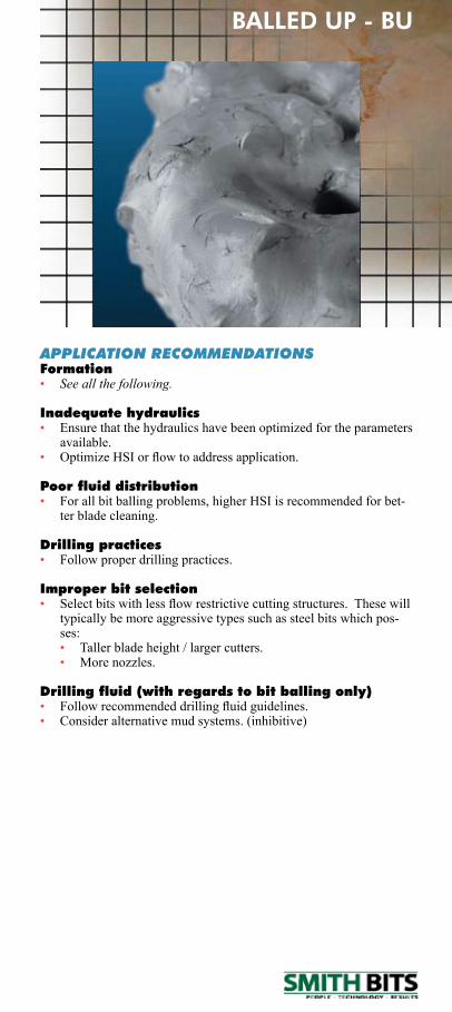
APPLICATION RECOMMENDATIONSFormation• See all the following.
Inadequate hydraulics• Ensure that the hydraulics have been optimized for the parameters
available.• OptimizeHSIorflowtoaddressapplication.
Poor fluid distribution• For all bit balling problems, higher HSI is recommended for bet-
ter blade cleaning.
Drilling practices• Follow proper drilling practices.
Improper bit selection • Selectbitswithlessflowrestrictivecuttingstructures.Thesewill
typically be more aggressive types such as steel bits which pos-ses:
• Taller blade height / larger cutters. • Morenozzles.
Drilling fluid (with regards to bit balling only)• Followrecommendeddrillingfluidguidelines.• Consider alternative mud systems. (inhibitive)
BALLED UP - BU
Fixed Cutter Dull Grading Manual
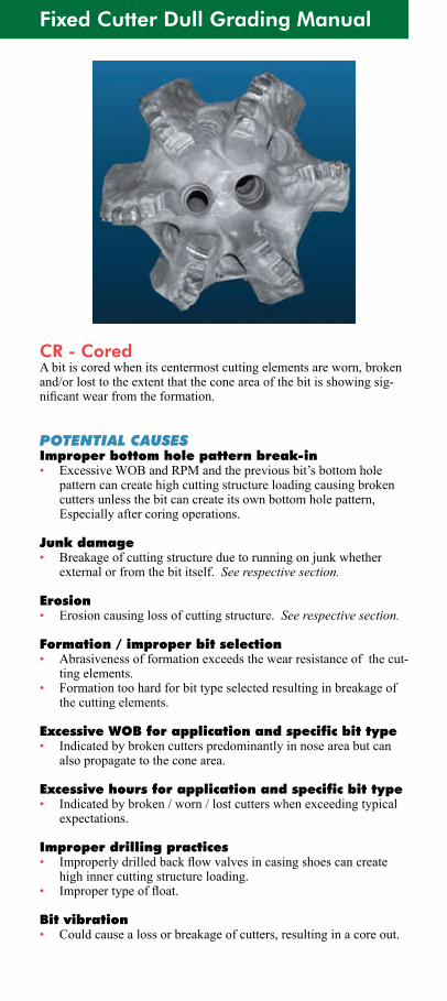
CR - Cored A bit is cored when its centermost cutting elements are worn, broken and/orlosttotheextentthattheconeareaofthebitisshowingsig-nificantwearfromtheformation.
POTENTIAL CAUSESImproper bottom hole pattern break-in• ExcessiveWOBandRPMandthepreviousbit’sbottomhole
pattern can create high cutting structure loading causing broken cutters unless the bit can create its own bottom hole pattern, Especially after coring operations.
Junk damage• Breakage of cutting structure due to running on junk whether
externalorfromthebititself.See respective section.
Erosion• Erosion causing loss of cutting structure. See respective section.
Formation / improper bit selection• Abrasivenessofformationexceedsthewearresistanceofthecut-
ting elements.• Formation too hard for bit type selected resulting in breakage of
the cutting elements.
Excessive WOB for application and specific bit type• Indicated by broken cutters predominantly in nose area but can
also propagate to the cone area.
Excessive hours for application and specific bit type• Indicatedbybroken/worn/lostcutterswhenexceedingtypical
expectations.
Improper drilling practices• Improperlydrilledbackflowvalvesincasingshoescancreate
high inner cutting structure loading.• Impropertypeoffloat.
Bit vibration• Could cause a loss or breakage of cutters, resulting in a core out.

CORED - CR
APPLICATION RECOMMENDATIONSImproper bottom hole pattern break-in• Proper bottom hole pattern break-in is considered to be when a
new bit achieves uniform cutting structure loading. This is done with light weights and slow rpm and is normally achieved with in6to12inches.AtthatpointWOBandRPMcanbegradually increased to typical operating levels.
Formation / improper bit selection• For hard formations, then select a bit with higher abrasion resis-
tance and/or impact resistance.
Excessive WOB for application and specific bit type• Optimize WOB for formation.• Consider using a shock sub or thruster.• For hard formations, then select a bit with smaller cutters and/or
higher blade count.
Improper drilling practices• Follow recommended procedures for drilling out cementing
equipment. Floats must be PDC drillable. Technical papers available from Smith Bits.
Bit vibration• Change operating parameters.
Fixed Cutter Dull Grading Manual
CT - Chipped CutterA cutting element is considered chipped if less than 1/3 of the cutting element is gone regardless of the cause. Chipping of diamond tables generally occurs on the outer most edge of a cutter.
POTENTIAL CAUSESFormation / improper bit selection• Improper cutter selection.• Formationtoohardforbittypeselected.Nospecificchippage
pattern.• Specificbittypesmaynotprovidesmoothdrillingcharacteristics.• Bitbouncingcancausechippage.Nospecificchippagepattern.
See “Broken Formations” below.• Cutters were subjected to numerous heat cycles (rebuild).Excessive WOB for application and specific bit type• Indicated by chipped cutters predominantly on the nose, but can
also occur on the gauge area.Excessive RPM for application and specific bit type• Indicated by chipped cutters predominantly in the gauge area.Broken formations (includes boulders)• Broken formations are those that have alternating hard and
softinterbeddedlaminatedsectionswithdistinctwelldefinedboundaries laid down at a angle. As drilling progresses through the bedding planes, pieces break at the bedding planes causing uneven loading on the cutting structure as the broken portions of formation move or roll under the bit.
Improper bottom hole pattern break-in• ExcessiveWOBandRPMandthepreviousbits’bottomhole
pattern can create high cutting structure loading causing chipped cutters unless the bit can create its own bottom hole pattern.
Excessive impact load / improper drilling practices• Dropping of the drill string.• Tagging bottom too hard / intentional spudding.• Hitting a ledge while tripping or making a connection.• Runningonjunk/floatnotPDCdrillable.• Improper casing clearances.Heat checking• See respective section.Bit vibration• Improper bit selection / BHA / operating parameters.
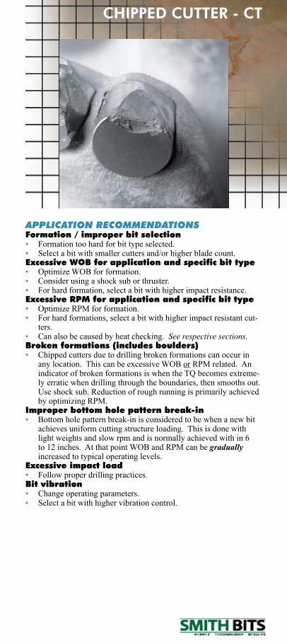
CHIPPED CUTTER - CT
APPLICATION RECOMMENDATIONSFormation / improper bit selection• Formation too hard for bit type selected.• Select a bit with smaller cutters and/or higher blade count.Excessive WOB for application and specific bit type• Optimize WOB for formation.• Consider using a shock sub or thruster.• For hard formation, select a bit with higher impact resistance.Excessive RPM for application and specific bit type• OptimizeRPMforformation.• For hard formations, select a bit with higher impact resistant cut-
ters.• Can also be caused by heat checking. See respective sections.Broken formations (includes boulders)• Chipped cutters due to drilling broken formations can occur in
anylocation.ThiscanbeexcessiveWOBorRPMrelated.AnindicatorofbrokenformationsiswhentheTQbecomesextreme-ly erratic when drilling through the boundaries, then smooths out. Use shock sub. Reduction of rough running is primarily achieved byoptimizingRPM.
Improper bottom hole pattern break-in• Bottom hole pattern break-in is considered to be when a new bit
achieves uniform cutting structure loading. This is done with light weights and slow rpm and is normally achieved with in 6 to12inches.AtthatpointWOBandRPMcanbegradually increased to typical operating levels.
Excessive impact load• Follow proper drilling practices.Bit vibration• Change operating parameters.• Select a bit with higher vibration control.
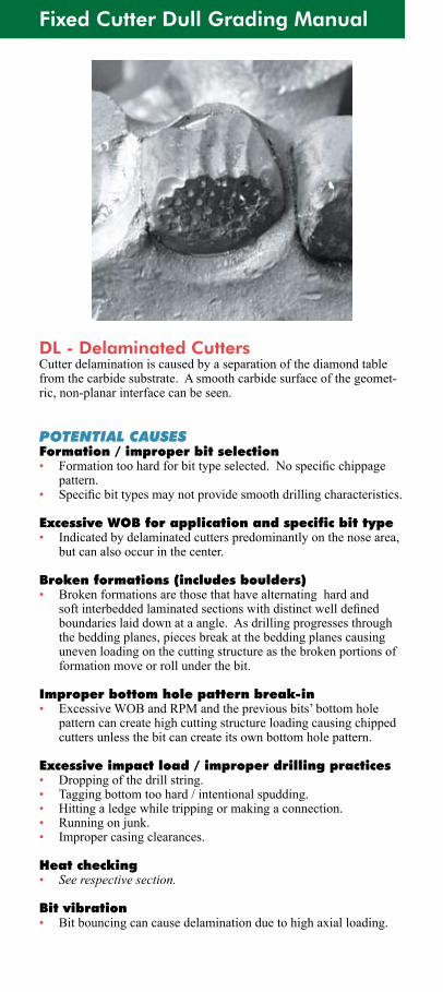
Fixed Cutter Dull Grading Manual
DL - Delaminated CuttersCutter delamination is caused by a separation of the diamond table from the carbide substrate. A smooth carbide surface of the geomet-ric, non-planar interface can be seen.
POTENTIAL CAUSESFormation / improper bit selection • Formationtoohardforbittypeselected.Nospecificchippage
pattern.• Specificbittypesmaynotprovidesmoothdrillingcharacteristics.
Excessive WOB for application and specific bit type• Indicated by delaminated cutters predominantly on the nose area,
but can also occur in the center.
Broken formations (includes boulders)• Broken formations are those that have alternating hard and
softinterbeddedlaminatedsectionswithdistinctwelldefinedboundaries laid down at a angle. As drilling progresses through the bedding planes, pieces break at the bedding planes causing uneven loading on the cutting structure as the broken portions of formation move or roll under the bit.
Improper bottom hole pattern break-in• ExcessiveWOBandRPMandthepreviousbits’bottomhole
pattern can create high cutting structure loading causing chipped cutters unless the bit can create its own bottom hole pattern.
Excessive impact load / improper drilling practices• Dropping of the drill string.• Tagging bottom too hard / intentional spudding.• Hitting a ledge while tripping or making a connection.• Running on junk.• Improper casing clearances.
Heat checking• See respective section.
Bit vibration• Bitbouncingcancausedelaminationduetohighaxialloading.
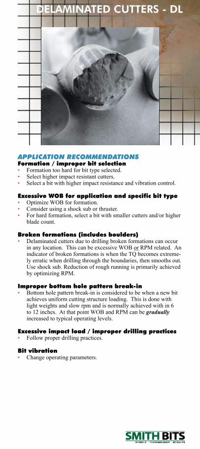
DELAMINATED CUTTERS - DL
APPLICATION RECOMMENDATIONSFormation / improper bit selection• Formation too hard for bit type selected.• Select higher impact resistant cutters.• Select a bit with higher impact resistance and vibration control.
Excessive WOB for application and specific bit type• Optimize WOB for formation.• Consider using a shock sub or thruster.• For hard formation, select a bit with smaller cutters and/or higher
blade count.
Broken formations (includes boulders)• Delaminated cutters due to drilling broken formations can occur
inanylocation.ThiscanbeexcessiveWOBorRPMrelated.AnindicatorofbrokenformationsiswhentheTQbecomesextreme-ly erratic when drilling through the boundaries, then smooths out. Use shock sub. Reduction of rough running is primarily achieved byoptimizingRPM.
Improper bottom hole pattern break-in• Bottom hole pattern break-in is considered to be when a new bit
achieves uniform cutting structure loading. This is done with light weights and slow rpm and is normally achieved with in 6 to12inches.AtthatpointWOBandRPMcanbegradually increased to typical operating levels.
Excessive impact load / improper drilling practices• Follow proper drilling practices.
Bit vibration• Change operating parameters.
Fixed Cutter Dull Grading Manual
ER - ErosionErosion is used to describe the loss of material on the cutting struc-tureduetotheimpactofthedrillingfluid,solidsandthecuttingsagainst the drill bit. Erosion can undermine the cutters, resulting in a lost cutter. In addition, erosion can wear away blade and body material.
POTENTIAL CAUSESInadequate hydraulics• Cuttings accumulate underneath the bit due to the lack of hydrau-
lic energy. These cuttings are re-cut again and again.
Excessive hydraulics• Highvelocityfluidcreatesturbulenceandimpingementonthe
blades and cutting elements.• Improper nozzle size combinations.
Abrasive formations• Cuttings from abrasive formations can cause erosion even with
minimum hydraulics.
Drilling environment• Abrasivedrillingfluids.(hematite)• Poor solids control.• Corrosive drilling environments enhance rate of erosion.
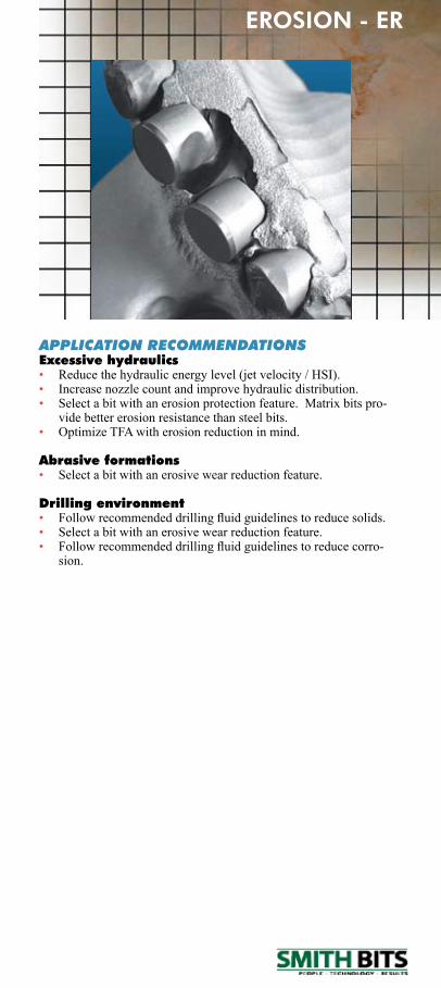
APPLICATION RECOMMENDATIONSExcessive hydraulics• Reduce the hydraulic energy level (jet velocity / HSI).• Increase nozzle count and improve hydraulic distribution.• Selectabitwithanerosionprotectionfeature.Matrixbitspro-
vide better erosion resistance than steel bits.• Optimize TFA with erosion reduction in mind.
Abrasive formations• Select a bit with an erosive wear reduction feature.
Drilling environment• Followrecommendeddrillingfluidguidelinestoreducesolids.• Select a bit with an erosive wear reduction feature.• Followrecommendeddrillingfluidguidelinestoreducecorro-
sion.
EROSION - ER
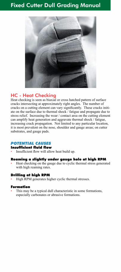
Fixed Cutter Dull Grading Manual
HC - Heat CheckingHeatcheckingisseenasbiaxialorcrosshatchedpatternofsurfacecracksintersectingatapproximatelyrightangles.Thenumberofcracksonacuttingelementcanvarysignificantly.Thesecracksiniti-ate on the surface due to thermal shock / fatigue and propagate due to stress relief. Increasing the wear / contact area on the cutting element can amplify heat generation and aggravate thermal shock / fatigue, increasing crack propagation. Not limited to any particular location, it is most prevalent on the nose, shoulder and gauge areas; on cutter substrates, and gauge pads.
POTENTIAL CAUSESInsufficient fluid flow• Insufficientflowwillallowheatbuildup.
Reaming a slightly under gauge hole at high RPM• Heat checking on the gauge due to cyclic thermal stress generated
with high reaming rates.
Drilling at high RPM• HighRPMgenerateshighercyclicthermalstresses.
Formation• This may be a typical dull characteristic in some formations,
especially carbonates or abrasive formations.
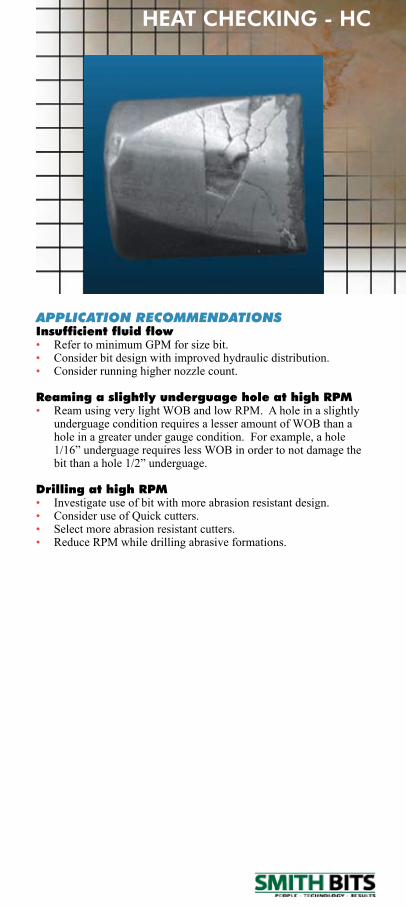
APPLICATION RECOMMENDATIONSInsufficient fluid flow• RefertominimumGPMforsizebit.• Consider bit design with improved hydraulic distribution.• Consider running higher nozzle count.
Reaming a slightly underguage hole at high RPM• ReamusingverylightWOBandlowRPM.Aholeinaslightly
underguage condition requires a lesser amount of WOB than a holeinagreaterundergaugecondition.Forexample,ahole1/16”underguagerequireslessWOBinordertonotdamagethebitthanahole1/2”underguage.
Drilling at high RPM• Investigate use of bit with more abrasion resistant design.• Consider use of Quick cutters.• Select more abrasion resistant cutters.• ReduceRPMwhiledrillingabrasiveformations.
HEAT CHECKING - HC
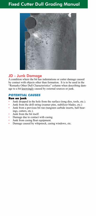
Fixed Cutter Dull Grading Manual
JD - Junk DamageA condition where the bit has indentations or cutter damage caused by contact with objects other than formation. It is to be used in the “RemarksOtherDullCharacteristics”columnwhendescribingdam-age to a bit knowinglycausedbyexternalsourcesorjunk.
POTENTIAL CAUSESRun on junk• Junk dropped in the hole from the surface (tong dies, tools, etc.).• Junk from the drill string (reamer pins, stabilizer blades, etc.)• Junk from a previous bit run (tungsten carbide inserts, ball bear-
ings, cutters, etc.).• Junk from the bit itself.• Damage due to contact with casing.• Junkfromcasingfloatequipment.• Damage caused by whipstock, casing windows, etc.
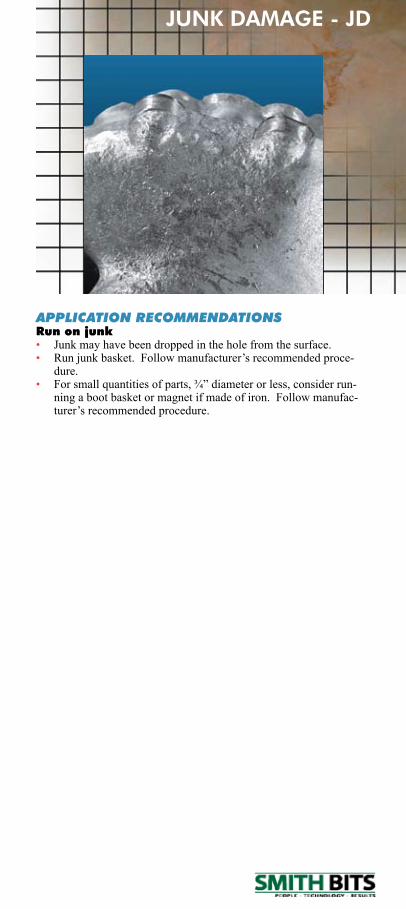
JUNK DAMAGE - JD
APPLICATION RECOMMENDATIONSRun on junk• Junk may have been dropped in the hole from the surface.• Runjunkbasket.Followmanufacturer’srecommendedproce-
dure.• Forsmallquantitiesofparts,¾”diameterorless,considerrun-
ning a boot basket or magnet if made of iron. Follow manufac-turer’srecommendedprocedure.
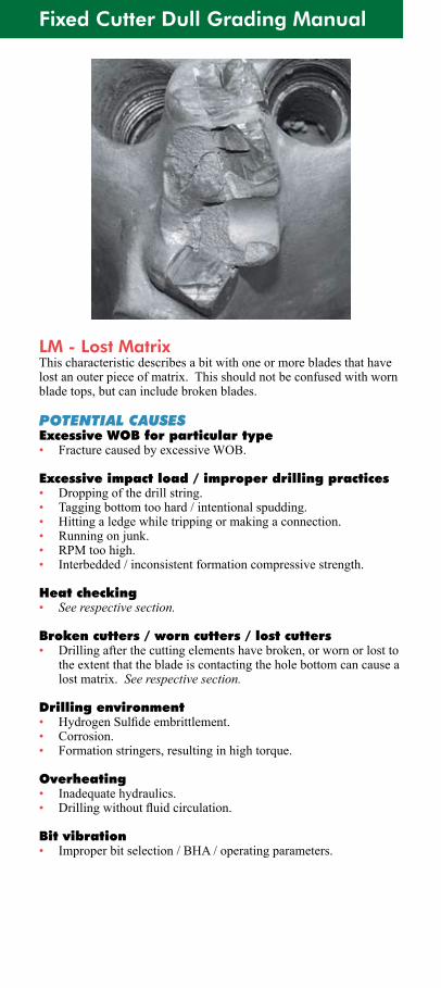
Fixed Cutter Dull Grading Manual
LM - Lost MatrixThis characteristic describes a bit with one or more blades that have lostanouterpieceofmatrix.Thisshouldnotbeconfusedwithwornblade tops, but can include broken blades.
POTENTIAL CAUSESExcessive WOB for particular type• FracturecausedbyexcessiveWOB.
Excessive impact load / improper drilling practices• Dropping of the drill string.• Tagging bottom too hard / intentional spudding.• Hitting a ledge while tripping or making a connection.• Running on junk.• RPMtoohigh.• Interbedded / inconsistent formation compressive strength.
Heat checking• See respective section.
Broken cutters / worn cutters / lost cutters• Drilling after the cutting elements have broken, or worn or lost to
theextentthatthebladeiscontactingtheholebottomcancausealostmatrix.See respective section.
Drilling environment• HydrogenSulfideembrittlement.• Corrosion.• Formation stringers, resulting in high torque.
Overheating• Inadequate hydraulics.• Drillingwithoutfluidcirculation.
Bit vibration• Improper bit selection / BHA / operating parameters.
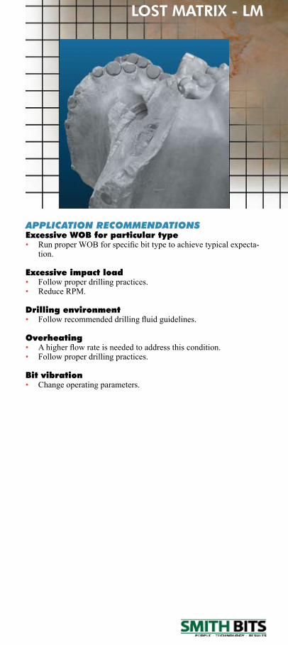
APPLICATION RECOMMENDATIONSExcessive WOB for particular type• RunproperWOBforspecificbittypetoachievetypicalexpecta-
tion.
Excessive impact load• Follow proper drilling practices.• ReduceRPM.
Drilling environment• Followrecommendeddrillingfluidguidelines.
Overheating• Ahigherflowrateisneededtoaddressthiscondition.• Follow proper drilling practices.
Bit vibration• Change operating parameters.
LOST MATRIX - LM
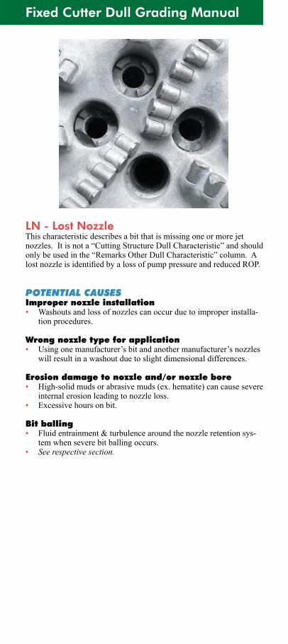
Fixed Cutter Dull Grading Manual
LN - Lost NozzleThis characteristic describes a bit that is missing one or more jet nozzles.Itisnota“CuttingStructureDullCharacteristic”andshouldonlybeusedinthe“RemarksOtherDullCharacteristic”column.AlostnozzleisidentifiedbyalossofpumppressureandreducedROP.
POTENTIAL CAUSESImproper nozzle installation• Washouts and loss of nozzles can occur due to improper installa-
tion procedures.
Wrong nozzle type for application• Usingonemanufacturer’sbitandanothermanufacturer’snozzles
will result in a washout due to slight dimensional differences.
Erosion damage to nozzle and/or nozzle bore• High-solidmudsorabrasivemuds(ex.hematite)cancausesevere
internal erosion leading to nozzle loss.• Excessivehoursonbit.
Bit balling• Fluid entrainment & turbulence around the nozzle retention sys-
tem when severe bit balling occurs.• See respective section.
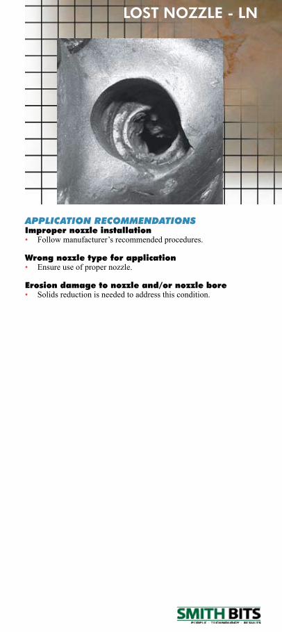
LOST NOZZLE - LN
APPLICATION RECOMMENDATIONSImproper nozzle installation• Followmanufacturer’srecommendedprocedures.
Wrong nozzle type for application• Ensure use of proper nozzle.
Erosion damage to nozzle and/or nozzle bore• Solids reduction is needed to address this condition.
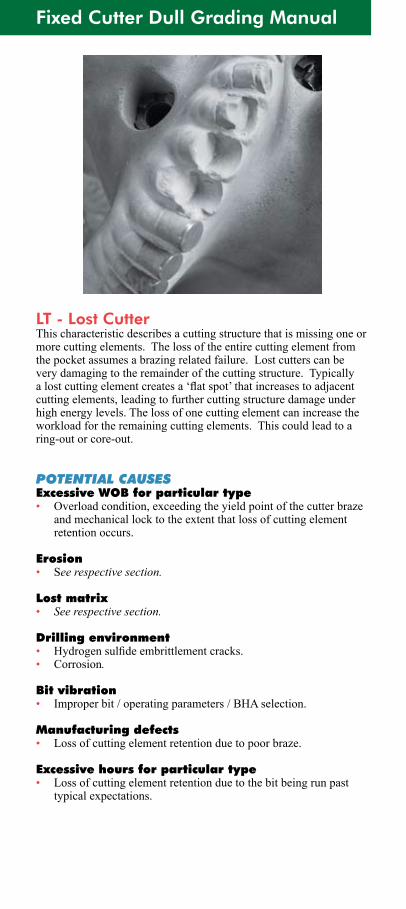
Fixed Cutter Dull Grading Manual
LT - Lost CutterThis characteristic describes a cutting structure that is missing one or more cutting elements. The loss of the entire cutting element from thepocketassumesabrazingrelatedfailure.Lostcutterscanbevery damaging to the remainder of the cutting structure. Typically alostcuttingelementcreatesa‘flatspot’thatincreasestoadjacentcutting elements, leading to further cutting structure damage under high energy levels. The loss of one cutting element can increase the workload for the remaining cutting elements. This could lead to a ring-out or core-out.
POTENTIAL CAUSESExcessive WOB for particular type• Overloadcondition,exceedingtheyieldpointofthecutterbraze
andmechanicallocktotheextentthatlossofcuttingelementretention occurs.
Erosion• See respective section.
Lost matrix• See respective section.
Drilling environment• Hydrogensulfideembrittlementcracks.• Corrosion.
Bit vibration• Improper bit / operating parameters / BHA selection.
Manufacturing defects• Lossofcuttingelementretentionduetopoorbraze.
Excessive hours for particular type• Lossofcuttingelementretentionduetothebitbeingrunpast
typicalexpectations.
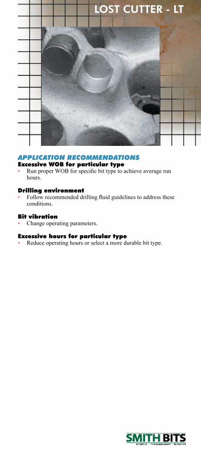
LOST CUTTER - LT
APPLICATION RECOMMENDATIONSExcessive WOB for particular type• RunproperWOBforspecificbittypetoachieveaveragerun
hours.
Drilling environment• Followrecommendeddrillingfluidguidelinestoaddressthese
conditions.
Bit vibration• Change operating parameters.
Excessive hours for particular type• Reduce operating hours or select a more durable bit type.
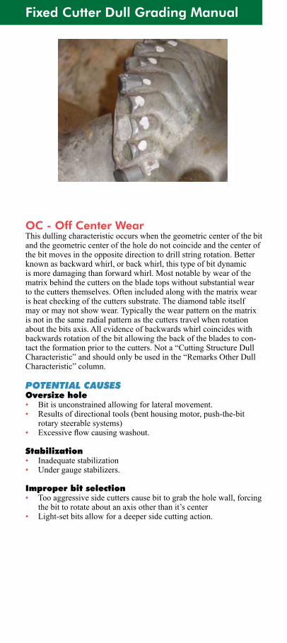
Fixed Cutter Dull Grading Manual
OC - Off Center WearThis dulling characteristic occurs when the geometric center of the bit and the geometric center of the hole do not coincide and the center of the bit moves in the opposite direction to drill string rotation. Better known as backward whirl, or back whirl, this type of bit dynamic ismoredamagingthanforwardwhirl.Mostnotablebywearofthematrixbehindthecuttersonthebladetopswithoutsubstantialweartothecuttersthemselves.Oftenincludedalongwiththematrixwearis heat checking of the cutters substrate. The diamond table itself mayormaynotshowwear.Typicallythewearpatternonthematrixis not in the same radial pattern as the cutters travel when rotation aboutthebitsaxis.Allevidenceofbackwardswhirlcoincideswithbackwards rotation of the bit allowing the back of the blades to con-tact the formation prior to the cutters. Not a “Cutting Structure Dull Characteristic”andshouldonlybeusedinthe“RemarksOtherDullCharacteristic”column.
POTENTIAL CAUSESOversize hole• Bit is unconstrained allowing for lateral movement.• Results of directional tools (bent housing motor, push-the-bit
rotary steerable systems)• Excessiveflowcausingwashout.
Stabilization• Inadequate stabilization• Under gauge stabilizers.
Improper bit selection• Too aggressive side cutters cause bit to grab the hole wall, forcing
thebittorotateaboutanaxisotherthanit’scenter• Light-setbitsallowforadeepersidecuttingaction.
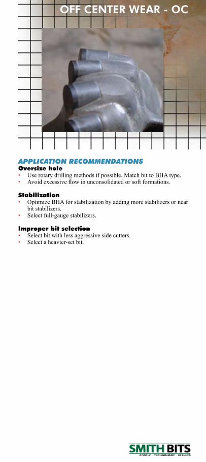
OFF CENTER WEAR - OC
APPLICATION RECOMMENDATIONSOversize hole• Userotarydrillingmethodsifpossible.MatchbittoBHAtype.• Avoidexcessiveflowinunconsolidatedorsoftformations.
Stabilization• Optimize BHA for stabilization by adding more stabilizers or near
bit stabilizers.• Select full-gauge stabilizers.
Improper bit selection• Select bit with less aggressive side cutters.• Select a heavier-set bit.
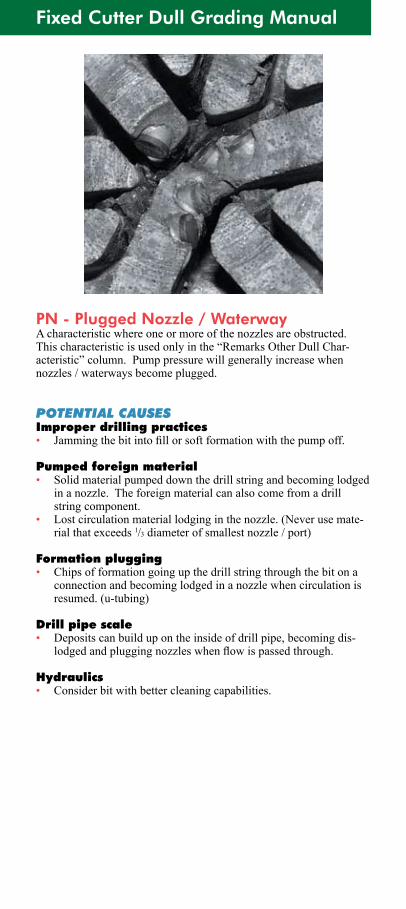
Fixed Cutter Dull Grading Manual
PN - Plugged Nozzle / WaterwayA characteristic where one or more of the nozzles are obstructed. This characteristic is used only in the “Remarks Other Dull Char-acteristic”column.Pumppressurewillgenerallyincreasewhennozzles / waterways become plugged.
POTENTIAL CAUSESImproper drilling practices• Jammingthebitintofillorsoftformationwiththepumpoff.
Pumped foreign material• Solid material pumped down the drill string and becoming lodged
in a nozzle. The foreign material can also come from a drill string component.
• Lostcirculationmateriallodginginthenozzle.(Neverusemate-rialthatexceeds1/3 diameter of smallest nozzle / port)
Formation plugging• Chips of formation going up the drill string through the bit on a
connection and becoming lodged in a nozzle when circulation is resumed. (u-tubing)
Drill pipe scale• Deposits can build up on the inside of drill pipe, becoming dis-
lodgedandpluggingnozzleswhenflowispassedthrough.
Hydraulics• Consider bit with better cleaning capabilities.
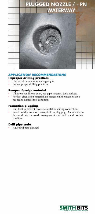
APPLICATION RECOMMENDATIONSImproper drilling practices• Use nozzle strainers when tripping in.• Follow proper drilling practices.
Pumped foreign material• Ifknownconditionsexist,usepipescreens/junkbaskets.• For lost circulation material, an increase in the nozzle size is
needed to address this condition.
Formation plugging• Runfloattopreventreversecirculationduringconnections.• Small nozzles are more susceptible to plugging. An increase in
the nozzle size or nozzle arrangement is needed to address this condition.
Drill pipe scale• Have drill pipe cleaned.
PLUGGED NOZZLE / - PN WATERWAY
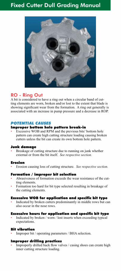
Fixed Cutter Dull Grading Manual
RO - Ring OutA bit is considered to have a ring out when a circular band of cut-tingelementsareworn,brokenand/orlosttotheextentthatbladeisshowingsignificantwearfromtheformation.Aringoutgenerallyisassociated with an increase in pump pressure and a decrease in ROP.
POTENTIAL CAUSESImproper bottom hole pattern break-in• ExcessiveWOBandRPMandthepreviousbits’bottomhole
pattern can create high cutting structure loading causing broken cutters unless the bit can create its own bottom hole pattern.
Junk damage• Breakage of cutting structure due to running on junk whether
externalorfromthebititself.See respective section.
Erosion• Erosion causing loss of cutting structure. See respective section.
Formation / improper bit selection• Abrasivenessofformationexceedsthewearresistanceofthecut-
ting elements.• Formation too hard for bit type selected resulting in breakage of
the cutting elements.
Excessive WOB for application and specific bit type• Indicated by broken cutters predominantly in middle rows but can
also occur in the nose rows.
Excessive hours for application and specific bit type• Indicatedbybroken/worn/lostinsertswhenexceedingtypical
expectations.
Bit vibration• Improper bit / operating parameters / BHA selection.
Improper drilling practices• Improperlydrilledbackflowvalves/casingshoescancreatehigh
inner cutting structure loading.

RING OUT - RO
APPLICATION RECOMMENDATIONSImproper bottom hole pattern break-in• Proper bottom hole pattern break-in is considered to be when a
new bit achieves uniform cutting structure loading. This is done with light weights and slow rpm and is normally achieved with in6to12inches.AtthatpointWOBandRPMcanbegradually increased to typical operating levels.
Formation / improper bit selection• Consider more abrasion resistant cutters.• Consider more abrasion resistant cutting structure.• Consider more impact resistant cutting structure.
Excessive WOB for application and specific bit type• Optimize WOB for formation.• Consider using a shock sub or thruster.• For hard formations, then select a bit with more blades and/or
smaller cutters.
Excessive hours for application and specific bit type• Select more durable bit type or reduce operating hours.• Broken and/or worn cutting elements can be reduced by decreas-
ing operating hours or by selecting a more robust cutting struc-ture.
Bit vibration• Change operating parameters.
Improper drilling practices• Refer to Recommend Drilling and Drillout Procedures.
Fixed Cutter Dull Grading Manual
SP - Spalled CuttersA partial fracture of the diamond table, similar to cutter delamination, butwherethenon-planarinterfaceisnotcompletelyexposedandsome diamond remains bonded to the carbide substrate.
POTENTIAL CAUSESFormation / improper bit selection• Bitselectiontooaggressive.Highpointloadingoncutters.Lack
of bit stability.
Excessive WOB for application and specific bit type• Depth of cut too deep.
Excessive RPM for application and specific bit type• Indicated by broken cutters predominantly on the ODR and gauge
due to high relative velocities and impact force generated .
Broken formations (includes boulders)• Broken formations are those that have alternating hard and
softinterbeddedlaminatedsectionswithdistinctwelldefinedboundaries laid down at a angle. As drilling progresses through the bedding planes, pieces break at the bedding planes causing uneven loading on the cutting structure as the broken portions of formation move or roll under the bit.
Improper bottom hole pattern break-in• ExcessiveWOBandRPMandthepreviousbit’sbottomhole
pattern can create high cutting structure loading causing broken cutters unless the bit can create its own bottom hole pattern.
Excessive impact load / improper drilling practices• Dropping of the drill string.• Tagging bottom too hard / intentional spudding.• Hitting a ledge while tripping or making a connection.• Running on junk.• Drill-out with hi-bend motors.
Bit vibration• Improper bit selection / BHA / operating parameters.
SPALLED CUTTERS - SP
APPLICATION RECOMMENDATIONSFormation / improper bit selection• Consider a more stable design.• Use more impact resistant cutters.• Reduce bit aggressiveness.• Reduce cutter loading.
Excessive WOB for application and specific bit type• Optimize WOB for formation.• Consider using a shock sub when anticipating numerous forma-
tion changes. See broken formations.
Excessive RPM for application and specific bit type• OptimizeRPMforformation.
Broken formations (includes boulders)• Brokencuttersduetodrillingbrokenformationscanoccurin
any location. An indicator of broken formations is when the TQ becomesextremelyerraticwhendrillingthroughtheboundaries,then smooths out. Consider using a thruster or shock sub.
Improper bottom hole pattern break-in• Bottom hole pattern break-in is considered to be when a new bit
achieves uniform cutting structure loading. This is done with light weights and slow rpm and is normally achieved within 6 to12inches.AtthatpointWOBandRPMcanbegradually increased to typical operating levels.
Excessive impact load / improper drilling practices• Follow proper drilling practices.
Bit vibration• Change operating parameters.
Fixed Cutter Dull Grading Manual
WO - Washed Out BitAwashoutiswheredrillingfluidhaserodedapassagefromaninternalflowareatotheexteriorofthebit.Thischaracteristicisusedonlyinthe“RemarksOtherDullCharacteristic”column.Ifallowedto continue, a washout may result in a twist off. A washout causes a decrease in pump pressure and ROP. Bit balling may also occur.
POTENTIAL CAUSESExcessive impact load• Acrackoccursduringthebitrunduetoexcessiveimpactor
fatigue. When a crack occurs and circulation starts through the crack,thewashoutisestablishedveryquickly.Causesofexces-sive impact are:
• Dropping of the drill string. • Tagging bottom too hard / intentional spudding. • Hitting a ledge while tripping or making a connection. • Running on junk. • Cyclic fatigue loading.
Improper bit / nozzle installation• Washouts can occur due to improper installation procedures.• Damaged threads, improper make-up torque• Pinched o-ring seal.
Wrong nozzle type for application• Usingonemanufacturer’sbitandanothermanufacturer’snozzles
will result in a washout due to slight dimensional differences.
Erosion damage to nozzle and/or nozzle retaining system• Highsolidmudsorabrasivemuds(ex.hematite)cancausesevere
internal erosion leading to nozzle loss.• Fluid entrainment and turbulence around retention system when
severe bit balling occurs.
Bit balling• Fluid entrainment and turbulence around the retention system
when severe bit balling occurs.• See respective section.
Bit vibration• Bit vibration can cause fatigue in tool joints of the BHA.
WASHED OUT BIT - WO
APPLICATION RECOMMENDATIONSExcessive impact load• Follow proper drilling practices.
Improper bit / nozzle installation• Followmanufacturer’srecommendedprocedures.
Wrong nozzle type for application• Ensure use of proper nozzle.
Erosion damage to nozzle and/or nozzle retaining system• It may not be desirable, practical or possible to reduce solids or
mud type.• See respective dull characteristic, “Balled-Up”.
Bit vibration• Change operating parameters.
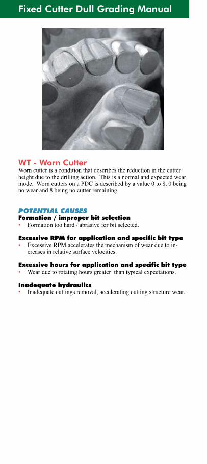
Fixed Cutter Dull Grading Manual
WT - Worn CutterWorn cutter is a condition that describes the reduction in the cutter heightduetothedrillingaction.Thisisanormalandexpectedwearmode.WorncuttersonaPDCisdescribedbyavalue0to8,0beingnowearand8beingnocutterremaining.
POTENTIAL CAUSESFormation / improper bit selection• Formation too hard / abrasive for bit selected.
Excessive RPM for application and specific bit type• ExcessiveRPMacceleratesthemechanismofwearduetoin-
creases in relative surface velocities.
Excessive hours for application and specific bit type• Wearduetorotatinghoursgreaterthantypicalexpectations.
Inadequate hydraulics• Inadequate cuttings removal, accelerating cutting structure wear.
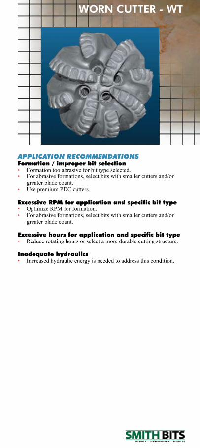
APPLICATION RECOMMENDATIONSFormation / improper bit selection• Formation too abrasive for bit type selected.• For abrasive formations, select bits with smaller cutters and/or
greater blade count.• Use premium PDC cutters.
Excessive RPM for application and specific bit type• OptimizeRPMforformation.• For abrasive formations, select bits with smaller cutters and/or
greater blade count.
Excessive hours for application and specific bit type• Reduce rotating hours or select a more durable cutting structure.
Inadequate hydraulics• Increased hydraulic energy is needed to address this condition.
WORN CUTTER - WT