dU/dt protection for distribution transformers - IPST -...
5
dU/dt protection for distribution transformers W. Piasecki, M. Ostrogórska, M. Florkowski, M. Fulczyk, P. Klys Abstract- very steep wavefront transients in power networks characterized by high dU/dt values pose significant risks as they can destroy motors, transformers, and other electrical equipment due to i) highly non-uniform initial potential distribution and ii) internal resonant phenomena resulting in local amplification of voltage. Overstressing the insulation system reduces significantly the equipment lifetime and often leads to an internal short-circuit. Based on the previous experience on the development and application of a series choke element upstream the protected device, aiming at mitigating the VCB (Vacuum Circuit Breaker) induced transients [1], a concept of using the series choke element to reduce stresses on the transformers induced by lightnings was developed. The parameters of the device were optimized for a class of small distribution transformers which have to comply with a standard, requiring testing the transformers with 2MV/us wavefront lightning impulse chopped at the front. Keywords: dU/dt protection, distribution transformers, lightnings I. INTRODUCTION Ultra steep wavefront transients characterized by high dU/dt values are extremely dangerous to the electrical equipment such as transformers and motors. According to [2] as many as 35% of total dielectric failures in power equipment are caused by surges [2]. The high frequency components present in the spectrum of the surge result in a very non- uniform potential distribution, leading to local overstressing of the insulation system. Due to the complicated internal structures of electrical apparatus resulting in a multi-resonant circuit nature, high frequency components may additionally lead to a local amplification of voltage. Overstressing the insulation system reduces significantly the equipment lifetime and often leads to internal short-circuit. It is well known that the voltage impulse withstand level depends strongly on the impulse rise time [2], [3]. This fact is typically taken into account in the insulation coordination studies for the electrical motors. Of special concern is in this case the dry type insulation of the rotating electrical machines fed by drives comprising solid state switching devices operating at a high frequency. Manufactures of the equipment therefore often provide guidelines regarding the limits of surge W. Piasecki, M. Ostrogorska, M. Florkowski, M. Fulczyk are with ABB Corporate Research Center in Krakow 31-038, Poland (e-mails: [email protected], [email protected], [email protected], [email protected]). P. Klys is with ABB Ltd, Aleksandrowska 67/93, Lodz 91-205, Poland (e-mail: [email protected]). Presented at the International Conference on Power Systems Transients (IPST’09) in Kyoto, Japan on June 3-6, 2009 voltage amplitudes and corresponding front times that machine can withstand without failures (Fig. 1). As seen in Fig.1, voltage withstand level is lower for shorter rise times. It is typically caused by non-linear voltage distribution along the winding resulting in higher, than assumed, voltage insulation stress causing breakdowns, corona and partial discharges [3]. Fig. 1. Dielectric withstands levels for medium voltage motors [2],[3]. II. PROBLEM DEFINITION The growing demand for increasing the withstand level of the distribution transformers results in a need to apply non- conventional design of the windings leading to increased cost of both the design and manufacturing of the transformers. Of special concern are transformers working in networks whose operators request compliance with a highly demanding norm, requiring testing the transformers with a steep-fronted impulse. According to a Finnish standard (SFS 2646), the steepness of the test voltage is 2MV/us [6]. The transformer, according to the norm is protected with a 2 x 40 mm double spark-gap located in a proximity to the transformer. The nature of a spark-gap, being a relatively slow device result in that the voltage at the transformer terminals may, under the test conditions, reach levels highly exceeding the standard BIL levels for a given transformer type. Moreover, the operation of any arc interrupting devices results in current chopping which produces substantial rates of current changes resulting in significant steep front overvoltage. Experimental results confirm the above and indicate that a spark gap may not provide sufficient protection for distribution transformers [4] of the standard design. The common solution to the problem is to apply a special winding design with increased insulation level and with additional elements equalizing the initial potential distribution. This approach complicates the design of the transformer and requires additional operations in the manufacturing process.
Transcript of dU/dt protection for distribution transformers - IPST -...
dU/dt protection for distribution transformers
W. Piasecki, M. Ostrogórska, M. Florkowski, M. Fulczyk, P. Kłys
Abstract- very steep wavefront transients in power networks
characterized by high dU/dt values pose significant risks as they can destroy motors, transformers, and other electrical equipment due to i) highly non-uniform initial potential distribution and ii) internal resonant phenomena resulting in local amplification of voltage. Overstressing the insulation system reduces significantly the equipment lifetime and often leads to an internal short-circuit. Based on the previous experience on the development and application of a series choke element upstream the protected device, aiming at mitigating the VCB (Vacuum Circuit Breaker) induced transients [1], a concept of using the series choke element to reduce stresses on the transformers induced by lightnings was developed. The parameters of the device were optimized for a class of small distribution transformers which have to comply with a standard, requiring testing the transformers with 2MV/us wavefront lightning impulse chopped at the front.
Keywords: dU/dt protection, distribution transformers, lightnings
I. INTRODUCTION
Ultra steep wavefront transients characterized by high dU/dt values are extremely dangerous to the electrical equipment such as transformers and motors. According to [2] as many as 35% of total dielectric failures in power equipment are caused by surges [2]. The high frequency components present in the spectrum of the surge result in a very non-uniform potential distribution, leading to local overstressing of the insulation system. Due to the complicated internal structures of electrical apparatus resulting in a multi-resonant circuit nature, high frequency components may additionally lead to a local amplification of voltage. Overstressing the insulation system reduces significantly the equipment lifetime and often leads to internal short-circuit.
It is well known that the voltage impulse withstand level depends strongly on the impulse rise time [2], [3]. This fact is typically taken into account in the insulation coordination studies for the electrical motors. Of special concern is in this case the dry type insulation of the rotating electrical machines fed by drives comprising solid state switching devices operating at a high frequency. Manufactures of the equipment therefore often provide guidelines regarding the limits of surge W. Piasecki, M. Ostrogorska, M. Florkowski, M. Fulczyk are with ABB Corporate Research Center in Krakow 31-038, Poland (e-mails: [email protected], [email protected], [email protected], [email protected]). P. Klys is with ABB Ltd, Aleksandrowska 67/93, Lodz 91-205, Poland (e-mail: [email protected]). Presented at the International Conference on Power Systems Transients (IPST’09) in Kyoto, Japan on June 3-6, 2009
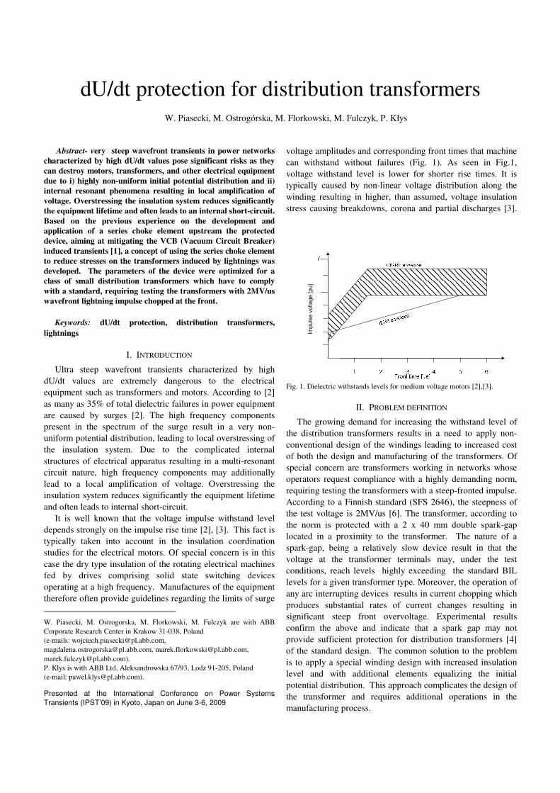
voltage amplitudes and corresponding front times that machine can withstand without failures (Fig. 1). As seen in Fig.1, voltage withstand level is lower for shorter rise times. It is typically caused by non-linear voltage distribution along the winding resulting in higher, than assumed, voltage insulation stress causing breakdowns, corona and partial discharges [3].
����������� ������
Fig. 1. Dielectric withstands levels for medium voltage motors [2],[3].
II. PROBLEM DEFINITION
The growing demand for increasing the withstand level of the distribution transformers results in a need to apply non-conventional design of the windings leading to increased cost of both the design and manufacturing of the transformers. Of special concern are transformers working in networks whose operators request compliance with a highly demanding norm, requiring testing the transformers with a steep-fronted impulse. According to a Finnish standard (SFS 2646), the steepness of the test voltage is 2MV/us [6]. The transformer, according to the norm is protected with a 2 x 40 mm double spark-gap located in a proximity to the transformer. The nature of a spark-gap, being a relatively slow device result in that the voltage at the transformer terminals may, under the test conditions, reach levels highly exceeding the standard BIL levels for a given transformer type. Moreover, the operation of any arc interrupting devices results in current chopping which produces substantial rates of current changes resulting in significant steep front overvoltage. Experimental results confirm the above and indicate that a spark gap may not provide sufficient protection for distribution transformers [4] of the standard design. The common solution to the problem is to apply a special winding design with increased insulation level and with additional elements equalizing the initial potential distribution. This approach complicates the design of the transformer and requires additional operations in the manufacturing process.

Fig. 2. Distribution transformer protected with spark gap according to the SFS 2646 standard [6].
III. SERIES IMPEDANCE BASED PROTECTION
An alternative to a special transformer design is to
introduce a series filtering element (choke) upstream the protected equipment. The concept of the series choke aiming at protecting the transformer against very fast transients associated with switching operations using vacuum circuit breakers (VCB) has been previously presented by the authors [1]. Experiments have shown that the use of the series impedance element enables one to efficiently suppress overvoltages and HF oscillations associated with pre-strikes and re-strikes during the switching operations.
The basic principle of the use of the series element is to provide an appropriate impedance-frequency characteristic, so that the device is transparent at 50/60 Hz but provides suppression for HF signals. It is achieved by a parallel connection of specially designed inductor/resistor combination [1].
Fig. 3. Concept of series device to protect distribution transformer against high dU/dt .
In the present article an extension of the application of the
series choke element to protect distribution transformers against ultra steep wavefront surges resulting form lightning surges is demonstrated. In this approach the phase-to-ground capacitance C ( see Fig. 3) is the equivalent phase-to-ground capacitance of the transformer. The concept is schematically presented in Fig. 4 showing an idealized picture of a voltage
waveform of a 2MV lightning impulse chopped at the front with a spark gap. It has been assumed, that the spark gap ignites within approx. 0.1�s from exceeding its protective level. The unprotected equipment (eg, pole-mounted transformer) would experience the phase-to-ground voltage of peak value exceeding 270kV, characterized by a dU/dt of 2MV/us. If the series choke element is installed upstream the protected device, its high frequency impedance combined with the phase-to-ground capacitance of the transformer form a low-pass filter, reducing the dU/dt but also, in consequence, the peak value of the voltage surge reaching the transformer. The transient simulations have shown that the series choke element is able to significantly reduce the steepness and overvoltage of front-chopped impulse (Fig. 4), when the transformer is represented by its equivalent phase-to-ground capacitance. However, introducing a series choke element with capacitive surge impedance brings about a potential risk of overvoltage and oscillations due to the resonant behavior while the electrical parameters of the particular elements are improperly selected. The issue of the right selection of the choke parameters is discussed in more detailed in the next section of the article.
Fig. 4. High-amplitude BIL (triangles), impulse chopped by spark gap (rectangles); after the choke (circles) both, the peak voltage value and dU/dt are reduced.
IV. SERIES CHOKE APPLICATION, DESIGN, AND OPTIMISATION
The series choke element described could be regarded as an alternative to the special winding design comprising the electrostatic screens for high frequency potential distribution equalization. The series choke element forms a low-pass filter when combined with a self capacitance of a transformer. The frequency response of such a filter must be optimized by

appropriate selection of the R and L parameters. Also, the choke behavior under normal operating conditions and its ability to withstand the short-circuit test must be verified.
The choke element for protecting small distribution transformers of a defined power and voltage range was designed and its parameters were optimized. The optimization was aiming at finding a solution providing a sufficient dU/dt reduction without a risk of oscillatory response and potential overvoltage generation.
The ability of reducing dU/dt values had therefore to be compromised with the fact that the system must not create oscillatory overvoltages when subjected to the standard BIL test. This requires appropriate resistive damping of the filtering circuit.
The load side of the choke element is, for high frequencies, represented by an input capacitance of the protected device. This capacitance may vary, depending on the type and size of the device. Typically, for oil-filled transformers this capacitance varies from a single to few nanofarads/phase. In case of dry transformers, this capacitance is significantly lower. Therefore, in some applications it is beneficial to increase the capacitance downstream the choke element by adding an additional set of phase-to-ground connected small surge capacitors. Such capacitors would have a double function: i) increasing the capacitance value downstream the choke element which allows for more dU/dt reduction for the same choke impedance, and ii) stabilizing the capacitance value by making it independent from the not-well defined input capacitance of the protected device. This latter feature is very important from the point of view of optimizing the non-oscillatory response of the choke-capacitor system (see Fig. 5).
Fig. 5. Simulated response of the choke – capacitor system to standard BIL test for various resistance values. The standard 1.2/50 µs BIL impulse is defined as a double exponential function:
)()( //0
BA tt eeUtU ττ −− −= (1)
where �A ,�B are time constants.
The response of the choke-capacitance system to the BIL is a linear combination of the exponential and the damped periodic functions. Depending on the relations between the R, L, and C values, the circuit response could be either aperiodic, or it could contain also oscillatory components. If the resistance value is lower than the critical value Rc, the periodic terms equal to zero and the output voltage is a combination of exponential functions:
)(1 �−
=i
t
iieAty τ (2)
For the resistance values above the critical Rc, the response contains the oscillatory terms and takes the form:
)sin()cos()( 4321121 teAteAeAeAty
tttt
ωω ττττ −−−−+++= (3)
The angular frequency (�) as well as Ai constants values depends on the relation between the resistance, capacitance, and the inductance values of the circuit. Even if the circuit is not critically damped however, and system response comprises the non-zero periodic terms (3), in some cases there are no oscillations visible. This situation takes place when the period of the oscillations is long as compared to the characteristic time of the exponential damping function. In practice, for the standard BIL test function (1), the oscillations are noticeable in the output voltage when the oscillation period is lower than 4x the time constant of the exponentially damped function ((2π/ω) < 4τ). The critical resistance value Rc is defined in (4) and the relation defining the resistance value for which the oscillations become visible (Rosc) is defined in (5). The Rosc value is always higher than Rc value (see Fig. 6).
4CL
Rc = (4)
)14
(4
2
+= πCL
Rosc (5)
Fig. 6. Circuit behavior nature for various resistance values.

V. EXPERIMENTAL VERIFICATION
The series chokes of parameters optimized for protecting a
small distribution transformers were designed, fabricated and test in a HV laboratory equipped with fast transient recording system. Schematic diagram of the test circuit is shown in Fig.7.
Fig. 7. Diagram of the test set – up; see text for details.
Ultra steep wavefront surges were generated using a
standard BIL generator (1.2/50us) and a sharpening circuit comprising the adjustable series spark gap (see Fig. 7).
The chokes were installed at the terminals (bushings) of a small distribution transformer (200kVA, 22kV-rated), as it is shown on Fig. 8. No external phase-to-ground capacitors were used and thus the capacitance C was just the equivalent capacitance of the transformer. During the test the voltage was connected to one of the phase terminals protected by the choke. The remaining terminals (also equipped with the chokes) were connected to the transformer tank and grounded.
Fig. 8. Connection of the chokes to the distribution transformer with measurement points marked.
The waveform shape at the input terminal of the
transformer in the test circuit shown in Fig. 8 is significantly affected by the object (transformer) parameters (the presence of the choke, and the grounding connector type, length, and shape). Therefore the parameters of the circuit have to be adjusted in order to achieve the required dU/dt value.
In the course of measurements voltages were recorded before and after the choke with reference to the common
grounding point. The waveforms were recorded using ultra-fast recording system.
Fig. 9. presents typical experimental results obtained. The left-hand side plot is the steep impulse voltage measured at the choke input. The peak voltage value is equal to 155 kV, in this case and the measured dU/dt value is almost 2.3 MV/us. The peak value exceeds the BIL level for this type of equipment (typically 95 or 125kV). It is important to note, that the peak level of the voltage during the experiment was characterized by a small dependence on the spark-gap electrodes distance. This points out that the transformers designed for lower voltage levels (and thus for lower BIL levels) would experience significantly higher risk of failure at similar conditions.
On the right-hand side plot in Fig. 9 the voltage measured at the transformer input is presented. The voltage magnitude is reduced down to 67 kV and dU/dt is reduced to 1 MV/us. The oscillatory components seen in both waveforms are the inevitable results of the inductances of the connections. The results obtained indicated that using the compact choke developed, a reduction in both dU/dt and Upeak value by a factor of 2 was achieved.
In order verify the non-oscillatory response of the choke-transformer system to the standard, full-wave BIL impulse, the sharpening circuit shown in Fig. 7. was disconnected. The waveforms were recorded at the choke input and at the transformer terminal. The results are presented in Fig. 10. It can be seen that neither oscillations characteristic for the underctitical damping, nor significant overshoot are present.
Fig. 9. Comparison of the voltage waveform recorded before and after the choke indicating the achieved level of dU/dt and overvoltage reduction. Left: voltage at the choke input; right: voltage at the transformer terminal
Fig. 10. Standard BIL test response for the transformer with choke attached; upper plot: voltage at the transformer terminal; lower plot: voltage at the choke input.
VI. CONCLUSIONS
Ultra steep wavefront transients characterized by high dU/dt values are extremely dangerous to the electrical equipment such as transformers and motors. In the article the case of transformers which must comply with the highly demanding standard requiring a type test with a 2MV/µs front waveform was analyzed. The common solution to the problem of high dU/dt withstand required, among the transformer manufacturers is to apply a special winding design with increased insulation level and with additional elements equalizing the initial potential distribution. This approach complicates the design of the transformer and requires additional operations in the manufacturing process.
An alternative to the special transformer design is to introduce a series filtering element (choke) upstream the protected equipment. It has been demonstrated that the choke parameters can be selected so that significant dU/dt reduction can be achieved without the oscillatory response of the choke-transformer system, provided that appropriate resistive damping is applied. The experiments performed confirmed that the choke installed at the phase terminal of a small distribution transformer reduced both the dU/dt and the peak value of the front-chopped wave by more than factor of two.
The response of the choke-transformer system showed that the presence of the appropriate resistive damping resulted in the absence of the oscillations and overshoots at the protected transformer terminal.
The results presented that the proposed solution based on an additional series choke is an alternative to the special winding design of the transformers which have to comply with thy highly demanding SFS 2646 standard.
VII. REFERENCES
[1] W. Piasecki, G. Bywalec, M. Florkowski, M. Fulczyk and J. Furgal,
"New approach towards Very Fast Transients suppression", Int. Conf. on Power Systems Transients IPST’2007, 4 – 7 June, 2007 – Lyon (France).
[2] K. C. Agrawal, "Industrial Power Engineering and application handbook", Newnes2001, p.584
[3] L. A. Saunders, G. L. Skibinski, S. T. Evon and D. L. Kempkes, "Riding the Reflected Wave – IGBT Drive Technology Demands New Motor and Cable Considerations", IEEE IAS – Petroleum & Chemical Industry Conference, Philadelphia, PA., Sept. 23 – 25,1996 pp. 75 – 84.
[4] L. M. Burrage, J. H. Shaw and B. W. McConnell, "Distribution transformer performance when subjected to steep front impulses", IEEE Transactions on Power Delivery, Vol. 5, No. 2, April 1990.
[5] Ch. H. Eichler, J. R. Legro and P. R. Barnes, "Experimental Determination of the effects of steep Front-short duration surges on 25 kVA pole mounted distribution transformers", IEEE Transactions on Power Delivery, Vol. 4, No. 2, April 1989.
[6] FINNISH STANDARDS SFS 2646, 1987-06-29, "Pole mounted substation".
VIII. BIOGRAPHIES Wojciech Piasecki was born on May 15,1966 in Poland. He received his MSc. in Electronics from the University of Science and Technology Cracow, Poland) and a PhD from the Jagiellonian University (Cracow, Poland). He has been working for many years in the area of electromagnetic and electrical phenomena, including high frequency and non-linear modeling of electrical equipment. Currently a researcher at the Corporate Research Center in Cracow. His main activity concentrated around transient network phenomena analysis
Magdalena Ostrogórska was born in 1983 in Poland. She received the
M.Sc. in Electrical Engineering from University of Science and Technology in Cracow (AGH) in 2007. She joined ABB Corporate Research in Cracow in 2008. Her research interests concentrates around protection of power equipment against very fast transients.
Marek Florkowski was born on July 3, 1965 in Kraków Poland. He received his M.S. and Ph.D degrees in Electronics from the University of Science and Technology (AGH) in Cracow in 1990 and 1994, respectively. From 1990 to 1992 he was employed at ABB Corporate Research Center in Baden-Dättwil, Switzerland. Currently he is responsible for ABB Corporate Research Center in Cracow, Poland. He is a member of IEEE and CIGRE.
Marek Fulczyk was born in 1968 in Poland. He received the M.Sc. and
Ph.D. degree in Electrical Engineering from the Wroclaw University of Technology/Poland in 1993 and 1997, respectively. In 1997 he joined ABB as a research scientist. Now he is a group leader of Electrical & Engineering Systems at ABB Corporate Research in Cracow, Poland. His fields of interests include power system protection, power system/voltage stability, real-time collaborative technology, 3D modelling and simulations of phenomena in power systems.
Paweł Kłys was born in 1965 in Poland. He received the M.Sc. in Electrical
Engineering from University of Science and Technology in Łód� in 1988. He has been working for many years in the area of design and manufacturing methods of distribution transformers. He is responsible for ABB Product Development Team for Distribution Transformers in Łód�.