DUCTILITY CONSIDERATIONS IN SEISMIC DESIGN OF HIGH RISE BUILDINGS2)0222.pdf · 222 DUCTILITY...
12
222 DUCTILITY CONSIDERATIONS IN SEISMIC DESIGN OF HIGH RISE BUILDINGS G. H. F. McKenzie* Abstract Design measures for providing earthquake re si stance in high rise buildings are set out. It is essential that any building designed to code seismic coef f icient s should have adequate duct ili ty, since its structure will be forced well into the yield range in a major earthquake. Methods of assessing the ductility require- ments in individual members of building frames are pre sented, together with procedure s for determining the values of 0 u /0y at individual hinge points, under seismic del lections into the plastic range. Conditions which give ri se to large values of 0 u /0 y are pointed out. Design problems involved in the formation of column hinge s are dealt with. Considerations affecting the use of dynamic analysi s for elasto-plastic response in de termining value s of 0 U /0 V at hinges are pointed out. Design procedures for sati sfying due t ili ty demands in individual members are di scussed. ( 1 ) Response of Elastic Systems It is well re cogni sed that adequate duct ili ty is an essential property of high ri se earthquake resistant buildings. Fig. 1 shows the smoothed acceleration response spectra for elastic systems, for the 19^0 El Centro Earthquake, N-S component. The curves show the re sponse for 2% critical damping and 10% critical damping respectively. In the same figure, the graph of the New Zealand Zone A design coefficients for Public Buildings is drawn 0 The load factors and undercapacity factors which are used in the New Zealand con- crete codes give minimum ratios of ultimate strength to design strength of 1.37 for beams and 1.79 for columns, Even after applying the se value s to the graph shown, it is obvious that the response movement of struetures must go well beyond the elastic 1 imit of deflection. ( 2 ) Elasto-Plastic Response Fig. 2 shows the idealised form of the load deflect ion graph of a simple reinforced concrete st rueture which is subjected to reversals of overload, producing deflections in each direction beyond the elastic 1 imit. The initial elastic deflection is shown by the line OA, the point A repre senting the load and deflection corres- ponding to the elastic limit. The post eleastic portion of the load-deflection graph is repre- sented by the horizontal line AB, pas sing through A, and the comple te cycle is shown by the figure OABCDEA. BC and DE are considered to be parallel to OA, and EB and CD are horizontal. In the first half cycle, the area of the triangle FAO * Assi stant Chie f Structural Engineer, N•Z« Mini stry of Works. represents the energy which is stored elastic- ally and pas sed to the next half cycle, while the area of the parallelogram ABPO represents the energy which is dissipated. Hence the ratio FB/FA is directly related to the propor- tion of the energy fed in during one half cycle which is dissipated as a result of the post elastic movement. This ratio is called the ductility factor and designated by the symbol yL( 9 and is defined as the ratio of maximum displacement/elastic displacement, (3 ) Decrease in Response Due to Ductility The effect of post elastic behaviour in damping down seismic response is demonstrated by the solid line graphs in Fig. 3 , which show the acceleration response spectra for 10% critical damping and different values of^, for the 19^0 El Centro Earthquake. (The graphs are drawn from information in Blume Newmark and Corn ing( * ) ) • The de crease in re sponse with increase in jy, is clearly shown. For reasons that will be made clear later in thi s paper, the highe st overal 1 value of /L which can be obtained in most structures is ^, and in some structures a lower value has to be accepted. The New Zealand seismic design code is based on /JL = k. (M Equal Deflection Rule and Reduction Factors It is found that the spectral di splacement for an elasto-plastic system is approximately the same as that for an elastic system having the same period of vibration. In other words, referring to Fig, if ab is the graph of re sponse for an elastic system, ade * would be the approximate graph of re sponse for an elastopla stic system, with e * lying on the vertical line bf. This rule will be used later in the paper to show various effect s. Referring to Fig, kf it can be shown that ce' _ fb cd " fe e or, in other words, yCC ~ base shear for elastic system base shear for elasto-plastic system Thus it can be said that the numerical value for the elasto-plastic reduction factor applied to elastic base shear is approximately equal to the ductility factor. However, it must be remembered that the two factors are fundament- ally different, one being a ratio of deflect- ions while the other is a ratio of base shears. The application of thi s approximate rule
Transcript of DUCTILITY CONSIDERATIONS IN SEISMIC DESIGN OF HIGH RISE BUILDINGS2)0222.pdf · 222 DUCTILITY...

222
DUCTILITY CONSIDERATIONS IN S E I S M I C DESIGN O F H I G H R I S E B U I L D I N G S
G. H. F. McKenzie*
Abstract
Design measures for providing earthquake re si stance in high rise buildings are set out. It is essential that any building designed to code seismic coef f icient s should have adequate duct ili ty, since its structure will be forced well into the yield range in a major earthquake.
Methods of assessing the ductility requirements in individual members of building frames are pre sented, together with procedure s for determining the values of 0 u/0y at individual hinge points, under seismic del lections into the plastic range. Conditions which give ri se to large values of 0 u / 0 y are pointed out. Design problems involved in the formation of column hinge s are dealt with. Considerations affecting the use of dynamic analysi s for elasto-plastic response in de termining value s of 0 U / 0 V at hinges are pointed out. Design procedures for sati sfying due t ili ty demands in individual members are di scussed.
( 1 ) Response of E last ic Systems
It is well re cogni sed that adequate duct ili ty is an essential property of high ri se earthquake resistant buildings. Fig. 1 shows the smoothed acceleration response spectra for elastic systems, for the 1 9 ^ 0 El Centro Earthquake, N-S component. The curves show the re sponse for 2% critical damping and 10% critical damping respectively. In the same figure, the graph of the New Zealand Zone A design coefficients for Public Buildings is d r a w n 0 The load factors and undercapacity factors which are used in the New Zealand concrete codes give minimum ratios of ultimate strength to design strength of 1 . 3 7 for beams and 1 . 7 9 for columns, Even after applying the se value s to the graph shown, it is obvious that the response movement of struetures must go well beyond the elastic 1imit of deflection.
( 2 ) E l a s t o - P l a s t i c Response
Fig. 2 shows the idealised form of the load deflect ion graph of a simple reinforced concrete st rueture which is subjected to reversals of overload, producing deflections in each direction beyond the elastic 1imit. The initial elastic deflection is shown by the line OA, the point A repre senting the load and deflection corresponding to the elastic limit. The post eleastic portion of the load-deflection graph is represented by the horizontal line AB, pas sing through A, and the comple te cycle is shown by the figure OABCDEA. BC and DE are considered to be parallel to OA, and EB and CD are horizontal. In the first half cycle, the area of the triangle FAO
* Assi stant Chie f Structural Engineer, N•Z« Mini stry of W o r k s .
represents the energy which is stored elastic-ally and pas sed to the next half cycle, while the area of the parallelogram ABPO represents the energy which is dissipated. Hence the ratio FB/FA is directly related to the proportion of the energy fed in during one half cycle which is dissipated as a result of the post elastic movement. This ratio is called the ductility factor and designated by the symbol
yL(9 and is defined as the ratio of maximum displacement/elastic displacement,
( 3 ) Decrease in Response Due to Ducti l i ty
The effect of post elastic behaviour in damping down seismic response is demonstrated by the solid line graphs in Fig. 3, which show the acceleration response spectra for 10% critical damping and different values o f ^ , for the 19^0 El Centro Earthquake. (The graphs are drawn from information in Blume Newmark and Corn ing( * ) ) • The de crease in re sponse with increase in jy, is clearly shown. For reasons that will be made clear later in thi s paper, the highe st o v e r a l 1 value of /L which can be obtained in most structures is ^, and in some structures a lower value has to be accepted. The New Zealand seismic design code is based on /JL = k.
(M Equal Deflection Rule and Reduction Factors
It is found that the spectral di splacement for an elasto-plastic system is approximately the same as that for an elastic system having the same period of vibration. In other words, referring to Fig, if ab is the graph of re sponse for an elastic system, ade * would be the approximate graph of re sponse for an elastopla stic system, with e * lying on the vertical line bf. This rule w i l l be used later in the paper to show various effect s.
Referring to Fig, kf it can be shown that
ce' _ fb cd " f e e
or, in other words,
yCC ~ base shear for elastic system base shear for elasto-plastic system
Thus it can be said that the numerical value for the elasto-plastic reduction factor applied to elastic base shear is approximately equal to the ductility factor. However, it must be remembered that the two factors are fundamentally different, one being a ratio of deflections while the other is a ratio of base shears.
The application of thi s approximate rule

223
0 0-5 1-0 1-5 2-0 2-5
Fig. 1. Undamped Natural Period in Seconds
Fig. 2. Elasto Plastic Response


( d by the dotted curves in Fig. 3 • -> a smooth curve drawn through the
^i_«,n for JM- 1. The two other dotted ir£ *m with ordinate s equal to J and -J-
of curve N o s 1. They generally ... c.osely to the graphs for JLL- 2 and ptcii /eiy,
225
The following demonstrates the extent to which the numerical correspondence of ductility factor and reduction factor depends on the form or the p c.rlhquake c If the applied earthquake c ^ i i i e d the extreme case of only one very r r & - (a type which has never been z <_ r 1 l CL / t ne reduction factor for undamped
.ir, /uuld be given by
wh ere k - e j. c s - o-piastic response acceleration -lestic response acceleration
j - _ _~ Ire ,:»a y iir.um response acceleration c_ : i over several cycles by a succession
- r .J ~ s n p u t ground pulses in phase with the ^ ~ s . _ a structure, the value of R would d r o p Q
_^ _j .ojs that the rule of numerical corres-i c- t- is not an exact one , and should be used
e j e c t s rather than precise numerical c .... _ 3 . T h i s is the use to which it will be put
_ a c r _ u ~ _ s p ap e r c
' f " ^hip Between Ductil ity Factor and Strain Factor
a s " ..ect in g into the plastic range, a - - - _ s ^ 1 _ usually develop a plastic hinge over a short portion of its 1ength, at the position at maximum momenta Very severe flexural strains are developed in the plastic hinge area, and it is the magnitude of these which u sually 1imi t s the ductility factor that any single member can develop,. The ratio ultimate strain/elastic strain for the hinge area is measured by the ratio
Expressions for calculating the length of a hinge are given by Baker ( 2 ) and Mattoc
where is the hinge curvature at ultimate deflection
and 0 is the hinge curvature at elastic y d e f l e c t i o n limit
(6 Relationship Between Overall Frame Ducti l ity
and Individual Member
It is obvious from previous parts of this paper that it is essential to determine the overall due tili ty of a structure. 1 f the seismic design coefficients have been derived from the assumption of a due t i 1 i ty factor of it is essential to ensure tha t a s t ruet ure can develop thi s ductility factor. Again, it is obv i ou s that a design base shear coefficient on its own doe s not define the seismic capaci ty of a structure. It is necessary to know the design base shear plus the due t ili ty fact or in order to assess the general se i smic pe rformanec of a s true ture of a gi ven na tural period.
As sume that de sign se i smic load is applied to a structure, and is then g r a d u a l 1 y increased until sufficient plastic hinge s are formed to prevent any further increase in sei smic resistance in the structure. The def 1ecti on of the strue ture is then increased by means of further ro tat ion of all plastic hinge s, wi thou t any further increase in 1oad. The que st i on arises as to what is the overall due t i 1 i ty factor of the structure. It can obviously not be answered in the general case purely on def 1ecti on con siderations, becau se a l 1 members will have dif ferent 1 o a d s , some membe rs w i 1 1 remain elastic while others will develop plastic hinge s, and the plast ic hinges in the most general case w i 1 1 not a l 1 form simultaneously. The method advocated by the wri ter is to use a strain energy concept.
Referring to Fig. 5 ( a ) , if the load-deflection graph repre sent s a simple member having a ductility fact or of k, the area ABE, donot ed by a, repre sent s the elastic strain energy, while the area b repre sent s the inelastic strain energy at the en d of one half cycle, Then if the ductility factor = k« a = J_b, and jL of the
^ 7
energy fed into the member in the half cycle is retained as elastic energy •
Hence it is important to determine the relationship b e t w e e n j & and 0̂
I T ry
7c- a single cantilever subjected to a • •;:?;,5t l a r ci s z r ibu t i on of bending moments it
0 u
1 - { l - n ) 3
/here n = length of hi nge length of single cantilever
i e r i c e , for a ductility factor of k,
12, 1 for n = — 7,2 for n 1
3
In any more complex system, such as a f rame, if ^ of the ene rgy f ed into it in a half cycle is re tai ned a s elastic energy, the system will have exactly the same base shear re spon se characteri sties as the simple member wi th ^/C = k. Hence, in such a case, the overall ductility f ac tor of the complex system can be said to be ka
Figs. 5(b) to (e) show load-deflection graphs for typical members in a frame. 5(b) shows a 1ightly 1oaded member which remains elastic, while 5(c) shows a more heavily 1o a d e d member which remain s elastic. Fig 0 5(d) shows a member which develops a plastic hinge early in the proce s s of 1 o a d increase, w h i 1 e Fig. 5(e) shows a member whi ch develope s a plastic hinge later. The area marked a in each graph repre sent s elastic ene rgy, wh i 1 e the area marked b in each graph represents inelastic
The above relationship can be applied to any portion of a f 1exural member-which is subjected to a triangular bending moment d i s t r i b u t i o n a
Mo s t members of a seismic frame can be dealt with on this ba sis, by dividing each be am or column into two single cantilevers, each extending from a joint to a point of inflectioru
226
energy. Then, from the argument in the previous paragraph, if
then the overall duet i 1i ty factor = k,
Alternately i f j a = | 2 b then the overall due t i 1i ty factor = 2 0
Thi s method is e x tremely gene ral in its appli cat i on o The individual load-deflect ion graphs can repre sent individual members or single storeys or other sub as semblage s of members, It is an extremely useful tool to a de signer, because it shows very qui ckly, in a simple visual manner, the effect of changing member proper!ie s 0 For ins tance, in graph 5 ( c )s the effect of stiffening the member on area a can be seen, Example s of its application w i 1 1 be shown later in the paper.
( 7 ) Duct i l i ty of Ordinary Building Frames Where
Hinges are Developed in Al l Beams
Consider the structure shown in Fig. 6(a) to be deflected into the inelastic range under the action of lateral sei smi c 1oad. As sume that hinges are f ormed in all beams, at the point s indicated by dot s. Next con sider separately the portion of the frame contained by the three dotted lines, which are positioned to pass through the points of inflection of the column and the beam. Thi s sub-as sembly consists of 3 si ngle cantilevers, wi th the i r "fixed" ends joined toge ther. The horizontal deflect ion of the 1ower of the two column points of inflect ion, from a vertical line passing through the beam-to-column joint can be considered as the sum of the foil owing 3 deflections, which are shown diagrammat ically in Figs. 6(b), 6(c) and 6(d)„
/ \ (Due to elastic deflection of beam)
y\ ^ (Due to elastic def 1ection of column)
(Due to inelastic deflection of b e a m )
Assume S is the shear at the column level being considered, and let the re spect ive strain ener-gie s due to the 3 component s above be re spect-ively U i , U2 and U3, U3 be ing inelastic.
Then U = ^ l 5 U = ^ 2 S and U o 3
The whole structure can be broken up into similar sub-assemblage s, and, if the effect of the lower port ion of the ground storey column is neglected, the foil owing relationship holds*
If, for the structure as a whole, JLL- ^ Then 2> 3 = 6 ( £ U 2 + £ 1 ^ ) ^
For y " = 2> 2U
3 = 2 <XU2 + I u i >
Corresponding relation ships hold for other values of ^ . The effect of the bottom portion of the ground storey column can be taken into account by including its elastic and inelastic energy areas in the above expressions.
The duct i 1ity factor for each beam is
equal to 3 > and the c orre spond ing 0U for
each beam hinge rotation demand can be calculated by the procedure set out in section (5).
Quite often, it w i 1 1 be sufficient to simply take typical assemblages near the t op of a buildi ng and near the bottom of a bu ilding. The beam hi nge demands can be checked in each case for a ductility factor of k in the as sembl age j when considered as a strueture on its own o However, in averaging out, it must be remembered that member s near the bo t torn have a great er effect on overall duet ility factor than tho se at the t op, be cau se the he ight s of f igure s are greater and hence areas are greater,
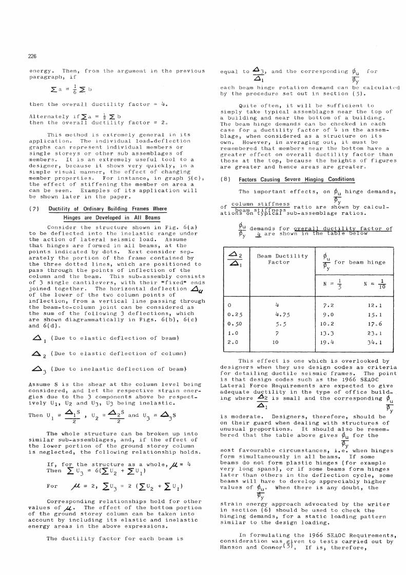
(8 ) Factors Causing Severe Hinging Conditions
The important effect s, on 0 U hinge demands,
of column stiff ne ss Vy ^ x —=- , . _ _ ratio are shown by cal cul -, . beam stiffness , , _ , . at I o n s on typical sub-assemblage ratios.
t}L demands for overall ductility factor of pZ j£ are shown in the table below
Beam Ductility Factor
0 beam hinge
N = To
0 k 7 . 2 1 2 . 1
o . 2 5 ^.75 9 . 0 1 5 . i Oo 50 5° 5 1 0 o 2 1 7 . 6
1.0 7 1 3 - 3 23o 1
2 0 0 10 1 9 . ^ 3 ^ . 1
Thi s effect is one whi ch is overlooked by de signer s when they use de sign codes as criteria f or detailing ductile sei smic frame s. The point is that de sign code s such as the 1 9 6 6 SEAOC Lateral Force Requirements are expected to give adequate ductility in the type of office building where ^2 is small and the corresponding 0
^ 1 I F ry
is moderate . De signers, therefore, should be on their guard when dealing with structures of unusual proportions 0 It should also be remembered that the table above gives 0 U for the
most f avourabl e circumstances, i«, e , when hinges form simultaneously in a l 1 beams. If some beam s do not form plastic hinge s (f or example very long spans), or if some beams form hinges later than others in the deflection cycle, some beams will have to develop appreciably higher values of 0 u O When there is any doubt, the
strain energy approach advocated by the writer in section ( 6 ) should be used to check the hinging demands, for a static loading pattern similar to the design loading.
In formulating the 1 9 6 6 SEAOC Requirements, consideration was given to tests carried out by Hanson and C o n n o r ^ 5 ) 0 if is s the refore,

227
B " ; c
Load /© ® / " a /© E a
Deflection Rg5 (a)
Fig 5(b) Fig 5(c)
Load
Elastic
Load / a b
Deflection-Fig 5(d)
Deflection-Fig 5(c)
Shear=S <—
Fig 6(a)

223 ( 1 0 ) Example of Building Designed for
a Ductil ity Factor of 2
An example of reducing the dueti 1ity factor is shown by the building in F i g s 0 8 to 1 0 . Because of requirements of the occupancy, the ground storey is high, wi th comparat ively slender columnso The upper storeys are much st if f er than the ground storey, and the beams are appreciably stronger than the columns. The result is that, under sei smic loading, the only members which develop plastic hinges are the bottorn storey columns, and the deflected shape is as shown by the line diagram Fig. 9•
The 0U values for the column hinges can
% be calculated by a very simple application of the strain energy principle already de scribed in section ( 6 ) . Load-deflection graphs are drawn for the horizontal interstorey deflection in each storey - i.e. the movement of each floor with respect to the floor below. The loading system used is the design distribution of seismic loading, increased up to the level at which hinges develop in the ground storey columns. Then, the load def 1ection graphs for the respective storeys are as shown in Fig. 1 0 . For the overall ductility factor to be k, the following relationship would have to hold. The inelastic area (b) of the ground storey graph would have to be 6 times the sum of (elastic area (a) of the ground storey graph plus the areas of the graphs for all the upper storeys). This would require a high value of 0U in the
column hinges. Area calculations show the following results, for rotations of column hinge s.
If overall value of J J L - k, 0U = 20 0 5 in columns
If overall value of JJL - 2 , 0U ~ 9 • 0 in columns
The value of 2 0 . 5 is too high even for structural steel. On the other hand, the value of 9 ° 0 can be sustained by reinforced concrete columns, provided that certain criteria, mentioned later in this paper, are satisfied. Note also that the writer has some fur ther re servat ions, mentioned later in the paper, on the general principle of allowing hinges to develop in reinforced concrete columns,
( 1 1 ) Frames Which Develop Hinges in Columns
Under Lateral Load
One of the main disadvantages of frames which develop hinges in columns under lateral load has been pointed out by P a r k ^ ' o This is that, if the columns in any storey develop hinges at top and bottom, they prevent hinges developing subsequently in any of the stories above that level. This drastically reduces the number of stories that can dissipate inelastic energy• The worst case occurs when the lowest storey develops column hinges before any other stories can. None of the storeys above can subsequently develop hinges, and hence a ductility condition similar to that of the building described in section ( 1 0 ) results. Referring back to the strain energy concept of section (6), the inelastic strain
of interest to compare the value of the beam 0U
calculated for the assemblage used in the tests, with the table above. The beam ^ duetili ty factor, for the value of JLL = 5 used in the tests, is approximately 7 . 0 5, and the corresponding value of 0U is approximately 1 8 . 2
The writer conside rs that, at the present state of knowledge, the design value for 0 U , in reinforced concre t e beams de signed to jfj^ wi thstarid seismic hinging, should be 1imited to a maximum of 1 5 j and, if possible, should be kept below 13•
( 9 ) Frames Where an Overall Ductil ity Factor of 4
Can Not Be Developed
It is fairly obvious from the above that it does require careful de sign to achieve an overall ductility factor of k. In buildings which, for one reason or another, d e v e 1 op plastic hinges in only a smal 1 proportion of the membe rs a duct ility factor of k can not be achieved. The que s tion arises as to whe ther it is sound practice to accept a lower duetility factor and compensate by requiring an appreciably higher base shear de sign coefficient,
For example, a building structure with a per iod of 0 0 h$ seconds and having 10% critical damping would require a base shear coefficient of 0, l6g toge the r with a duct il ity fact or of k to resist the 19 ^0 El Centro earthquake. If we refer to Fig. 3, we find that the same structure with a ductility factor of 2 would require a yield strength of approximately 0 . "}0^ for the El Centro earthquake.
Hence a de signer may think it reasonable to de sign for a sei smic coeff icient of 0 . 3 0 f and accept a ductility factor of 2. In the writer's opinion, thi s approach require s caution, because it gives less margin for coping wi th earthquakes greater than the de sign one.
Referring to Fig. 7s assume that ab is the load deflect ion graph for the elastic spectral re sponse to the design earthquake• Then, assuming the equal deflection rule is applicable, (as set out in section (k) )
ade is the elastoplast ic re sponse f or /A, - U ade 1 is the el as t oplast ic re sponse forJUL = 2
As sume a greater earthquake now comes, and elastic response is increased by 2 5 % , as shown by the line af. Then, using the equal deflection rule again, the two elasto-plastic systems are repre sented by the graphs adh and a d 1 h » . It is apparent that the larger earthquake has the fol 1owi ng effects on the two sy stems 0
System designed f or JUL - 2; plastic range movement increased by 5 0 %
System designed for JJL - ^; plastic range move- ^ ment increased by 33-^%
Hinge rotations are approximately propor-t ional to plast ic range movement s 0 Hence, the system wi th JUL ~ ^ can cope wi th the larger earthquake wi th only -j of the increase in hinge rot at i ons required by system with JUL - 2 0
Hence, it is advisable to 1imit the design value s of 0U to 1 ower value s for JUL- 2 than
tho se recomme nded for JjL ~ ^.

Load
a
229
/
b/ A
A / I
/ i
/ d ' /
A=2
K = 4
e' 'h' i
•Deflection Line for Design Earthquake
h
Deflection. Fig 7 Effect of k Value on Response to Earthquake
Greater than the Design Earthquake.
1 D D Q D D D D D D D D D D D D D D D D D Q D D D n D D D D D D Q D D D D
Fig 8 Lateral Frame. Fig 9 Deflected Shape.
3rd storey 2nd storey.
Fig 10 -Load-Deflection Curves for Individual
Storeys. Load
1st s torey.
Ground Storey. Deflection-

230 energy in the bottom storey alone has to balance the sum of the elastic strain energy in all storeys. Thi s will result in very high hinging demands in the bot torn storey columns. Even if a very much reduced duct ili ty factor for the buiIding a s a whole is adopt ed, the values of 0U in the bottom storey columns may
still be too h i g h c
The ideal answer is obviously to make col urnn s stronger t h a n beams at a l 1 joints. However, this is not always possible-for example the need for long beam spans or for deep spandrel beams on exterior walls may make it impractical to make columns stronger than beams throughout.
If the problem of hi nge s forming in columns applies to only one or two stories of a building, a f a i r 1 y safe solution to the problem can generally be found by making these stories appreciably stronger in relation to lateral design load then the other stories of the building. This will ensure that hinges form in all the other stories of the building before the column hinges form. In a l 1 cases where this is done, it is e ssential that the 0U values for
1*7 individual membe r s should be che eked by the strain energy procedure s set down in section (6 ) . This is because the unbalance in storey strengths will tend to increase the hinging demands in some member s, and also becau se the hinging capac ity in column s is 1imit ed and he nee the column rotations need to be carefully controlled.
The condition where columns in all storeys are weaker than the beams is more difficult. In a 3 storied buiIding with long spans, the writer has tackled this problem by progressively increasing the rat io of lateral storey strength design storey load, in pas sing from each storey to the next one d o w n 0 For example, the top storey could be de s igned for de s ign load x load factor, the next one down for de sign load x 1c i 5 x load factor and the next one down for de sign load x 1.30 x 1.f. As sei smic re sponse increased, hinge s could be expected to form first in the top storey and then progressively down the building in all the other stories. Thi s basi s of de sign can obviously be used only in buildings wi th a small number of stories. Once again, the value s of 0 U
should be checked in individual m e m b e r s 9 by the strain energy method of ^ section ( 6 ) s be cau se of the possibility of unbalance in hinging demands, and becau se of the limited hinge rotation capacity of columns•
Even in the typical case where hinges are developed in all beams, as shown in Fig. 6 ( a ) , it is obvious that a hinge would form at the bottom of each ground storey column 0 Thi s form of hinging does not prevent hinge s from forming in other stories, so it doe s no t have the objections of the other forms di scu s sed. However, it still give s reason for concern, in view of the 1imit ed 0U capacity of reinforced
concrete column s, and consequently the yw
value for this hinge, result ing from the ove r a l 1 due t i 1 i ty factor assumed, should be calculat ed.
( 1 2 ) Hinge Rotation Capacity of Reintorced Concrete Columns
In all case s where an appreciable value of 0U is developed at column hinges, it is e ssent-Ty ial to be able to assess the column capaci ty in this respect, Recommendat ions for 1imi t ing values for beam hinge s have been given at t he end of s e c t i o n ( 8 ) , but the limiting values for column hinge s are 1ower and are aff ecte d by o the r pa rame t e r s such as axial load. The re is practically no test data on the hinging capacity of reinforced concrete columns of the size used in the 1ower storeys of high rise buildings , and the only experimental evidence whi ch the wr i t er has seen publi shed has been on s m a l 1 laboratory test pieces. A theoretical ba si s for a s se s s i ng 0 U capaci ty of column s ha s been
^ d i given by Blume e t al , and the wri ter recommends the use of thi s approach in the m e a n t i m e , but it should be appli ed conservatively in the absenc e of adequat e e xperiment al data.
In Blume, Newmark and Corning section 5•^ deals wi th this que stion, and the associated Fig. 5 - 16 gives the theoreti cal variation in
with change in axial load. It will be noted
that, for a 0U of 9 . 0 (required for the building
described in section ( 1 0 ) of thi s paper, to give an overall value of 2 for the column axial load has to be 1imit ed to 1 9 % of the ultimate axial load, which is a fairly onerous restriction on the de sign of a high rise buiIding . If the column load rises to 2 5 % of ult imate axial load capaci ty, then the 0U
capaci ty drops to 5 . Admit t edly the 1ongi tudinal steel percentage in the column of figure 5 - 1 6 is high, at 5 % of gross area, and a lower steel percentage will give rather higher values of 0U capaci ty, (The corre spond-
Ty ing curve for 1ower steel percentages can be calculated from Fig. 5 - 1 7 in Blume et al.) Again st thi s, however, the assumed stress strain curve for concrete, on whi ch Fig. 5 - l 6 is based, is shown in Fig. 5 - 1 5 , and thi s curve assume s that (a) conf ined concrete can be subjected to a maximum strain of 0 . 0 1 and (b) by inference that rectangular tied columns can be rein forced to give thi s degree of confinement in the core. Neither of the se assumptions have been proved by test for the dimensions and de tailing used in large rectangular tied columns, as designed for the 1ower stories of high rise buildings. Hence, a safety margin for the present state of knowledge should be appli ed to the theoretical curve s, and the writer thinks that the prudent designer should keep value s of 0U in columns below 1 0. Even
Ty for the se value s, the 1imi tat i on of axial load and the longitudinal steel percentage should be kept below the appropriate 1 i m i t s derived from the theoretical approach of Blume et a l .
It should be remembered, incidentally, that if a hinge in a 1 o we r storey column is grossly weakened by excessive rotati on, to the extent that it can no 1onger safely carry its heavy permanent axial load, it may be almost impo s s ible to repair, be cause it is usually

out of the question to temporarily remove the a x 1 a 1 load, On the other hand, if a beam hinge is weakened by excessive rotation, it can more easily be repaired, by propping the beam on either side of 1 lie hinge, and cutting out and replacing the damaged concrete (and reinforcement also, if necessary)« This is an additional reason why column hinges must be designed on a much more conservative basis*
( 1 3 ) Dynamic A n a l y s i s for Elasto - Plastic Response
A dynamic analysis that will give inelastic response is an essential procedure for the design of important buildings or buildings with unusual features,. If high hinging demands in some members result from lack of balance in member strengths or unfavourable stiffness rati o s, or if t he r e is any reason to expect high hinging demands in some members arising in the higher mode s of vibration, a dynamic analysis should be carried out* The dynamic analysis method must obviously be one from which the 0u values for individual member hinges can be calculated.
2 3 1
The dynamic analysis is complementary to the strain energy procedure wh i ch was de scribed in sec t i o n (6) for determining the i ndi v idual values of 0 corresponding to a given overall
^ y value of ju, for the frame. The strain energy procedure is more of a tool for design (as compared with analysis) in that a designer can see at a glance what will be the approximate effect of changi ng stiffness or strengths of different members on the hinge rotations at different points in the frame or on the overall frame ductility f ac t or c Again, the dynami c analysis gives the response to a particular earthquake, (or several selected earthquakes) while the strain energy procedure gives a more general result; n a m e 1 y the o v e r a l 1 ductility factor corresponding to 1 i m i t ing values of 0 U . The overal 1 due t il i t y f act or can be considered as an absolute parameter of earthquake resistance, for assessing the general seismic performance of the structure. On the other hand, the dynami c analysis ha s the advantage of showing higher mode effects and does give an exact distribution of sei smi c re sponse up the height of the structure f or the part icular ear thquake re cord whi ch is being appli ed.
( N e c e s s i t y to Apply Load Factors to Earthquake used
for Dynamic A n a l y s i s
It must be remembered that de signers apply mult iplying fac tor s such as load factor s to thei r de sign l o a d s , a s a very nece s sary saf e ty measure to obtain final member strengths. Hence, any analysis result s which are used in design must incorporat e the se 1 o a d fac tor s. It is accepted that the static strength of a reinforced concrete member must be equal to 1 . 2 5 ( D + L + E) and that 0 = 0 0 ° 0 for beams.
In other w o r d s , the final member strength must be based on 1 . 2 5 / ^ , T , T - \
( D + L + E)
= 1 . 3 7 (D + L + E) ! R 1 )
To be consistent with thi s, the dynamic analy si s mu s t also be carried out f or 1 . 3 7 (D + L + E)c In other words, the values of D + L and the applied earthquake must be scaled
If, for example, M n + j - M £ at beam hinge point s, then actual seismic strength at beam hinge points in the finally designed member, from relationship (R^) above,
= ( 1 . 3 7 x 2 M £ ) - M £ = l 0 7 ^ M £
In other words, the actual base shear yield strength would be 1 . 7 ^ x design base shear.
Assume that the dynamic response spectrum of an earthquake showed that, for the natural period of the structure concerned, a base shear of 0 . lOy combined with a ductility factor of k would give a structure which would only just survive the earthquake, without any margin. The designer, using normal procedures, would then design a structure which would have an overall ductility factor of k and an actual base shear strength of 1 . ?k x 0 , 1 0 ^ , which is 0o . The factor of 1 . y k is an essential safety measure to take account of various contingencies.
However, if the finally designed structure was then subjected to the same earthquake, it would develop an overall ductility factor of only 2 0 3 (assuming that the equal deflection rule of section k holds approximately) because the actual base shear strength is now 1 . 7 * + times the design base shear, and the individual member ductility factors developed would correspond to this much lower figure^ If the designer worked out the hinge rotations required from these results, he would be providing for a system which could only develop a ductility factor of 2 . 3 0 . In other w o r d s , he finally designs a structure which has a base shear strength of 0. and a d u c t i 1 i ty fact or of 2 * 3 0 , instead of a base shear strength of 0.l combined with a ductility factor of U, whi ch is required. His designed structure is equivalent in dynamic resistance to one with a base shear strength of the bare O.lOy and a ductility factor of ^ a It will barely survive the design earthquake, without any safety margin for material understrength or uncertainty of applied 1 o a d i ng.
Hence it is apparent that, to obtain the required ductility factor, in a structure where seismic plastic hinges are developed in
up by 1 . 3 7 before being applied to the final structure, The structure with hinge 0 U values
designed on these results will then have a safety factor of 1 , 3 7 on the required dy namic resistance for the combined loading.
Although this last requirement appears f u n d a m e n t a l s it is surprising to see the numbor of elasto-plastic dynamic response investigations published where the earthquake applied to t lie final designed structure lias been the actual record without" any scaling factor, Those have naturally shown individual member excursions into the plastic range which are far too low. The following calculations will make the point clearer,
From the relationship above marked R^, it is apparent that the earthquake strength capacity at yield point of the finally designed membe r s is :-
1 . 3 7 ( D + L + E ) - ( D + L) , R 2

232 requirements are not a mathematically exact response to one particular earthquake, but rather an envelope of responses f or a v a n ety of possible earthquakes. Any individual peculiarities in the response character!sties of the earthquakes used should be looked at critically and a decision made as to whether the unusual features should not be modified. The relationship between items in the response curves such as relative magnitude of fundamental and higher modes, phase relationships between fundamontal and higher modes at maximum response and whether fundamental and higher modes reach maximum response amplitudes during the same cycle should all be examined by the designer.
( 19 ) Design of Frame Structures for Ducti l ity
There is not sufficient space left to go into the actual design of members to provide the required d u c t I 1 i t y, so the writer's comments must be confined to general principles. Most of the codes for design of ductile moment resisting frames are based on the 1 9 6 6 SEAOC Lateral Force 1 Requirements, or modifications of these. A previous paper by the writer'' 7) draws attention to features of such methods which appear to requi re fur t her con side ra t i on . It is emphasized again that the SEAOC method assumes that one starts off with a structure in which the 0U values of the various hinges are
moderate, due to favourable balance between member strengths and favourable raCios of column stiffness to beam stiffness, as explained in sections (8) to (10) of this present paper.
It is also emphasized that the SEAOC procedures visualize only beam hinges forming. The columns are given a moderate hinging capacity adjacent to joints to allow for accidental column hinge f ormat i on 0 This is to cover the effects of stiff w a 1 1 panels or stairs which may have effects of locally stiffening floors or stories that have been overlooked, or p o s s ibly even the effects of changes in direction of storey shear for higher modes of vibration. These should involve only small values of 0 U
unless the designer has been grossly negligent in incorporating major features ^ of irregularity into the structure. However, most buildings contain a s m a l 1 number of column hinges which are inherent in the fundamental action of the bu ilding - usually at the bottom of the bottom storey columns, as shown in Fig. 6(a)c The se will involve la rge r value s of 0U and the comments made in sections ( 1 1 )
and (12) of the present paper should be considered in dealing with the se 0 These hinges should be treated on a di fferent basi s from the accidental hi nge s, be cau se their rotation condit ions are more severe, the designer is certain that they will develop, they are few in number and their positions are def init ely known. Also, theyr occur at the most heavily loaded parts of the columnso The expense of special details wi t h we 1 d e d fabricat ion of conf ining oponents is just ified f or these condi t ions, Sugge s t ions for su ch details are given in the writer's i or such details earlter paper'^'.
References
( 1 ) Blume, J o A. , Newmark, N. M. , and Corning, L. H. ( 1 9 6 1 ) 1 "Design of Multistorey Reinforced Concrete Buildings for Earth-
beams, the dynamic elasto-plastic analysis should be based on scaling up earthquake records and (Dead + Live Load) all by a factor of 1 . 3 7 .
Similar reasoning wi 11 show that , where the seismic plastic hinges are developed in columns, all loading for the dynamic analysi s should be sea 1ed up by 1 . 2 5 = 1 . 7 9 .
0 . 7 0
( 1 5 ) Necessity for Correlation of Earthquake Records with
S moothed Response Curves
The acceleration response spectra for earthquake records are fairly irregular curves, with pronounced local troughs and peaks. if the structure has a period which is in a local trough of the response curve for the particular earthquake used, its response in terms of excursions into the plastic range will correspond to the value of this trough: These values are unrealistically low as a basis for design, because (a) another earthquake is unlikely to ha v e a local trough a t exactly the same period? and (b) one cannot guarantee that the finally built structure will have exactly thai period, and the final period may even correspond to an adjacent peak.
Hence the ampiltude of the applied earthquake in such a case should be scaled up to that corresponding to the smoothed response curve•
( l 6 ) Necess ity for Correlation with Loading
Code Base Shears
For longer period bu i 1 dings it can be seen from Fig. ( 3 ) that the response to the 1 9 ^ 0 El Centro earthquake, for a ductility factor of 4 , of structures wi th periods great er than 1.2 sees., is much less than the Zone A coefficients for Public Buildings required by the N. Z. Code. Thi s is because the N. Z * Code provide s for some amplification of ground mot ion for long period buildings due to soil effect s. The ear t hquake applied in the dynamic analysis should also be scaled up, so that its elasto-plastic response a t the peri od concerned is equal to the code base shear, to take account of such effects. Alternately, the de signer may be able to use some other procedure to obtain a reali st ic assessment of the modif i ca t i on of surface re spons e due to soil condi t ions.
( 1 ? ) Cumulative Application of Scaling F actors
for Dynamic A n a l y s i s
The factors referred to in sections ( lU) to ( l 6 ) for scaling up the record of the applied earthquake in dynamic analysis should be applied cumulatively for the various effects described.
/ 1 o \ ^ e ^ e c t ' o n ° f Earthquake Records for Dynamic A n a l y s i s
Thi s is a mat t er to which the designer must give careful thought and it is one on which the designer w i 1 1 find it most difficult to det e rmine a satisfactory bas i s for his choice.
He should consider sueh mat t er s a the distance of hi s structure from possible epicentres, the nearness of any f a u 1 1 lines, soil conditi ons in the area and, of cour se, the previou s seismic history of the area. Hi s
quake Motions". Portland Cement Association, U.S.A. Baker, A.L.L. and Amarakone, A.M.N. (196k) "Inelastic Hyperstatic Frames Analysi s" c
Proceedings of the International Symposium on the Flexural Mechanics of Reinforced Concrete, 8 5 - 1 3 6 . A . S . C . E . - A . C . I . Corley, W. G. {1966)1 "Rotational Capacity of Reinforced Concrete Beams". Journal of the Structural Division, A . S . C . E . 92 (ST5) 1 2 1 - l h 6 . Mattock, A. H. ( 19 6 7 ) : Di scu ssion on reference ( 3 ) • Journal of the St ructural Division, A.S.C.E., 9 3(ST2) 5 1 9 - 5 2 2 . Hanson, N. W. and Connor I I. W. {1967)1 "Seismic Resistance of Reinforced Concrete Beam-Column Jo int s" 0 Journal of the Structural Division, A.S.C.E., 9 3(ST5) 5 3 3 - 5 6 0 . Park, R. ( 1 9 6 8) : "Ductility of Reinforced Concre te Frames Under Sei smi c Loading". N . Z . Engineering, 2 3(11) ^ 2 7 - ^ 3 5 . McKenzie G.H.F. ( 1 9 6 9): "A Critical Look at the Design of Reinforced Concrete for Ductility." Bull. of the N . Z . Society for Earthquake Engineering. 2 ( 3 ) 2 9 5 - 3 0 7 .


![Gioncu [Framed Structures. Ductility and Seismic Response - 2000]](https://static.fdocuments.us/doc/165x107/5532c8424a79599f5e8b4753/gioncu-framed-structures-ductility-and-seismic-response-2000.jpg)


