Dual-Rate 1000BASE-SX and 10GBASE-SR SFP+ …... 5 DUAL-RATE 1000BASE-SX AND 10GBASE-SR SFP+ 850NM...
17
Dual-Rate 1000BASE-SX and 10GBASE-SR SFP+ 850nm 300m DOM Transceiver • 1000BASE-SX 1G Ethernet • 10GBASE-SR/SW 10G Ethernet 1 www.fs.com DUAL-RATE 1000BASE-SX AND 10GBASE-SR SFP+ 850NM 300M DOM TRANSCEIVER Application • Hot-pluggable SFP+ footprint • Supports 9.95 to 10.5 Gb/s bit rates • Power dissipation < 1W • RoHS-6 compliant (lead-free) Features SFP-10GSR-85 • Receiver limiting electrical interface • Duplex LC connector • Built-in digital diagnostic functions • Commercial temperature range 0°C to 70°C • Single 3.3Vpower supply • Maximum link length of 400m on OM4 MMF • Uncooled 850nm VCSEL laser
Transcript of Dual-Rate 1000BASE-SX and 10GBASE-SR SFP+ …... 5 DUAL-RATE 1000BASE-SX AND 10GBASE-SR SFP+ 850NM...

Dual-Rate 1000BASE-SX and 10GBASE-SR SFP+ 850nm 300m DOM Transceiver
• 1000BASE-SX 1G Ethernet
• 10GBASE-SR/SW 10G Ethernet
1www.fs.com
DUAL-RATE 1000BASE-SX AND 10GBASE-SR SFP+ 850NM 300M DOM TRANSCEIVER
Application
• Hot-pluggable SFP+ footprint
• Supports 9.95 to 10.5 Gb/s bit rates
• Power dissipation < 1W
• RoHS-6 compliant (lead-free)
Features
SFP-10GSR-85
• Receiver limiting electrical interface
• Duplex LC connector
• Built-in digital diagnostic functions
• Commercial temperature range 0°C to 70°C
• Single 3.3Vpower supply
• Maximum link length of 400m on OM4 MMF
• Uncooled 850nm VCSEL laser
Description
Product Specifications
2www.fs.com
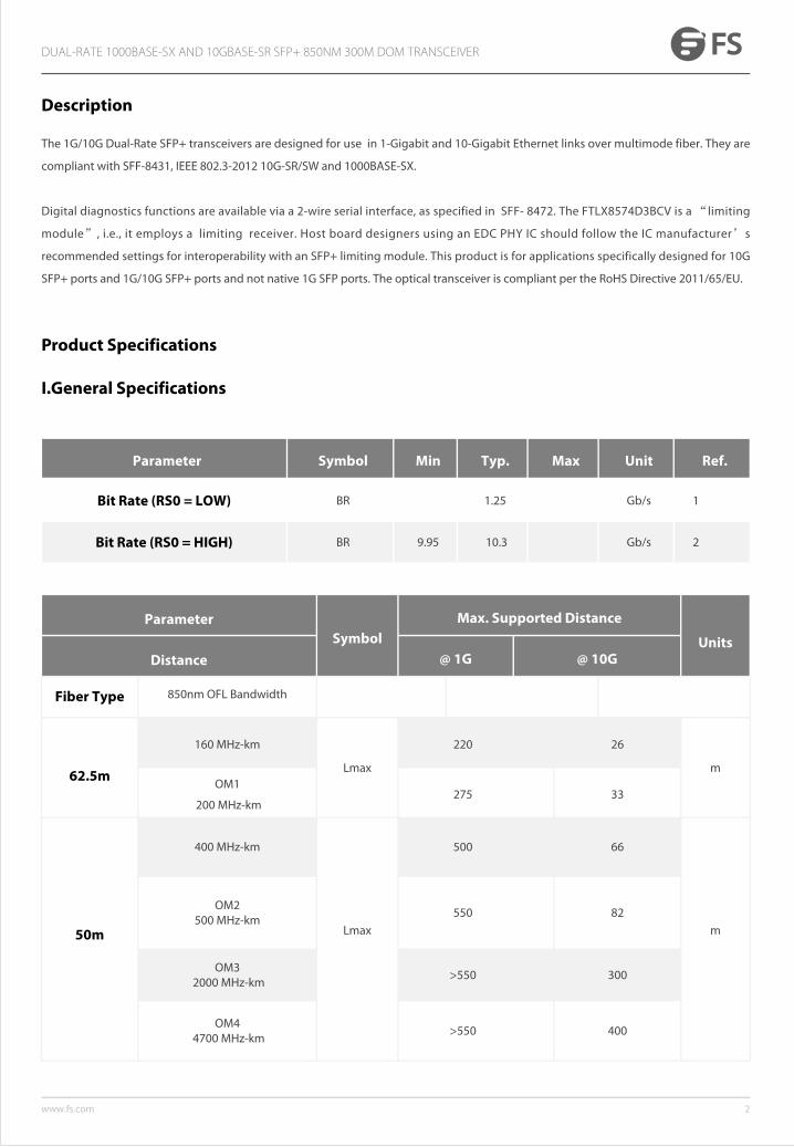
I.General Specifications
Parameter Symbol Min Typ. Max Unit Ref.
Bit Rate (RS0 = LOW) BR 1.25 Gb/s 1
Bit Rate (RS0 = HIGH) BR 9.95 10.3 Gb/s 2
DUAL-RATE 1000BASE-SX AND 10GBASE-SR SFP+ 850NM 300M DOM TRANSCEIVER
The 1G/10G Dual-Rate SFP+ transceivers are designed for use in 1-Gigabit and 10-Gigabit Ethernet links over multimode fiber. They are
compliant with SFF-8431, IEEE 802.3-2012 10G-SR/SW and 1000BASE-SX.
Digital diagnostics functions are available via a 2-wire serial interface, as specified in SFF- 8472. The FTLX8574D3BCV is a “limiting
module”, i.e., it employs a limiting receiver. Host board designers using an EDC PHY IC should follow the IC manufacturer’s
recommended settings for interoperability with an SFP+ limiting module. This product is for applications specifically designed for 10G
SFP+ ports and 1G/10G SFP+ ports and not native 1G SFP ports. The optical transceiver is compliant per the RoHS Directive 2011/65/EU.
ParameterSymbol
Max. Supported Distance
UnitsDistance @ 1G @ 10G
Fiber Type 850nm OFL Bandwidth
62.5m
160 MHz-km
Lmax
220 26
mOM1
200 MHz-km275 33
50m
400 MHz-km
Lmax
500 66
m
OM2 500 MHz-km
550 82
OM3 2000 MHz-km
>550 300
OM4 4700 MHz-km
>550 400
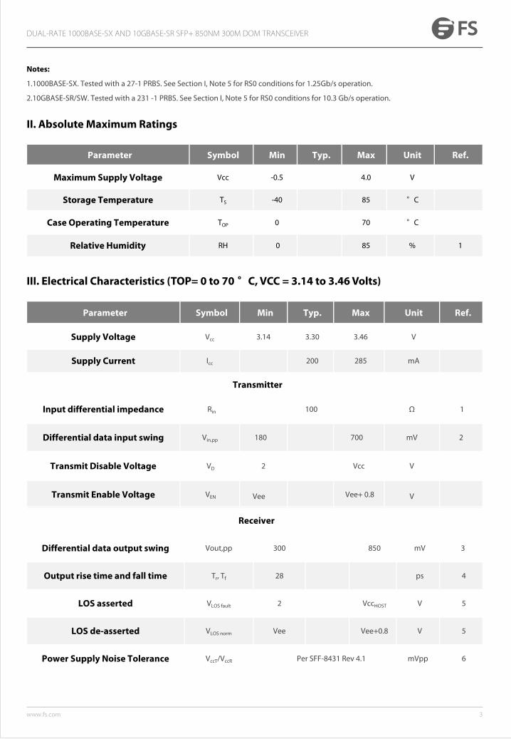
II. Absolute Maximum Ratings
3www.fs.com
Parameter Symbol Min Typ. Max Unit Ref.
Maximum Supply Voltage Vcc -0.5 4.0 V
Storage Temperature TS -40 85 °C
Case Operating Temperature TOP 0 70 °C
Relative Humidity RH 0 85 % 1
III. Electrical Characteristics (TOP= 0 to 70 °C, VCC = 3.14 to 3.46 Volts)
Parameter Symbol Min Typ. Max Unit Ref.
Supply Voltage Vcc 3.14 3.30 3.46 V
Supply Current Icc 200 285 mA
Transmitter
Input differential impedance Rin 100 Ω 1
Differential data input swing Vin,pp 180 700 mV 2
Transmit Disable Voltage VD 2 Vcc V
Transmit Enable Voltage VEN Vee Vee+ 0.8 V
Receiver
Differential data output swing Vout,pp 300 850 mV 3
Output rise time and fall time Tr, Tf 28 ps 4
LOS asserted VLOS fault 2 VccHOST V 5
LOS de-asserted VLOS norm Vee Vee+0.8 V 5
Power Supply Noise Tolerance VccT/VccR Per SFF-8431 Rev 4.1 mVpp 6
DUAL-RATE 1000BASE-SX AND 10GBASE-SR SFP+ 850NM 300M DOM TRANSCEIVER
Notes:
1.1000BASE-SX. Tested with a 27-1 PRBS. See Section I, Note 5 for RS0 conditions for 1.25Gb/s operation.
2.10GBASE-SR/SW. Tested with a 231 -1 PRBS. See Section I, Note 5 for RS0 conditions for 10.3 Gb/s operation.

4www.fs.com
Notes:
1. Connected directly to TX data input pins. AC coupling from pins into laser driver IC.
2. Voltage swing for 1G operation is equivalent to voltage swing in 10G operation (SFF-8431 Rev 4.1).
3. Into 100Ωdifferential termination.
4. 20 – 80%. Measured with Module Compliance Test Board and OMA test pattern. Use of four 1’s and four 0’s sequence in the PRBS 9
is an acceptable alternative.
5. LOS is an open collector output. Should be pulled up with 4.7kΩ – 10kΩ on the host board. Normal operation is logic 0; loss of signal is
logic 1. Maximum pull-up voltage is 5.5V.
6. Testing methodology per SFF-8431. Rev 4.1.
IV. Optical Characteristics for RS0 = HIGH (10G Operation)
(TOP = 0 to 70 °C, VCC3 = 3.14 to 3.46 Volts)
DUAL-RATE 1000BASE-SX AND 10GBASE-SR SFP+ 850NM 300M DOM TRANSCEIVER
Parameter Symbol Min Typ. Max Unit Note
Transmitter
Average Launch Power PAVE -9.5 -1 dBm 1
Optical Wavelength λ 840 850 860 nm 2
Rise-Fall Time Trise/Tfall 0.26 ns 3
RMS Spectral Width ∆λrms 0.45 dB
Optical Extinction Ratio ER 9 dB
Average Launch power of OFF transmitter POFF -30 dBm
Tx Jitter Txj Per IEEE 802.3-2012 Table 38-10
Relative Intensity Noise RIN12OMA -117 dB/Hz
Coupled Power Ratio CPR 9 dB

5www.fs.com
DUAL-RATE 1000BASE-SX AND 10GBASE-SR SFP+ 850NM 300M DOM TRANSCEIVER
Receiver
λC 840 860 nm 2
Receiver Sensitivity RSENS -17 dBm
Stressed Receiver Sensitivity 50 μm MMF SRS50um -13.5 dBm 4
Stressed Receiver Sensitivity 62.5 μm MMF
SRS62um -12.5 dBm 4
Maximum Input Power PMAX +0.5 dBm
Return Loss Rrx 12 dB
Receive electrical 3dB upper cutoff frequency
1500 MHz 2
LOS De-AssertLOS De-Assert LOSD -18 dBm
LOS Assert LOSA-30 -23 dBm
LOS Hysteresis 0.5 dB
Notes:
1. Max is equivalent to 10G max spec.
2. This product has not been designed to support 780-nm laser operation.
3. 20%-80%.
4. Per IEEE 802.3-2012. 9dB extinction ratio transmitter.
6www.fs.com
DUAL-RATE 1000BASE-SX AND 10GBASE-SR SFP+ 850NM 300M DOM TRANSCEIVER
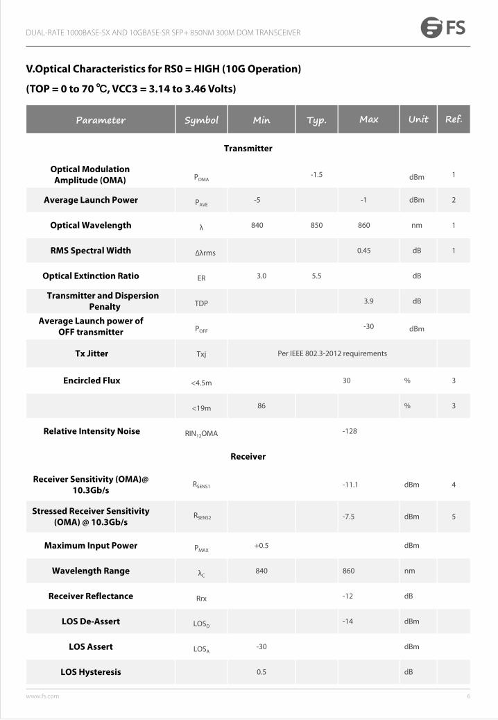
V.Optical Characteristics for RS0 = HIGH (10G Operation)
(TOP = 0 to 70 , VCC3 = 3.14 to 3.46 Volts)
Parameter Symbol Min Typ. Max Unit Ref.
Transmitter
Optical Modulation Amplitude (OMA) POMA
-1.5 dBm 1
Average Launch Power PAVE-5 -1 dBm 2
Optical Wavelength λ 840 850 860 nm 1
RMS Spectral Width ∆λrms 0.45 dB 1
Optical Extinction Ratio ER 3.0 5.5 dB
Transmitter and Dispersion Penalty TDP 3.9 dB
Average Launch power of OFF transmitter POFF
-30 dBm
Tx Jitter Txj Per IEEE 802.3-2012 requirements
Encircled Flux <4.5m 30 % 3
<19m 86 % 3
Relative Intensity Noise RIN12OMA -128
Receiver
Receiver Sensitivity (OMA)@ 10.3Gb/s
RSENS1 -11.1 dBm 4
Stressed Receiver Sensitivity (OMA) @ 10.3Gb/s
RSENS2 -7.5 dBm 5
Maximum Input Power PMAX+0.5 dBm
Wavelength Range λC840 860 nm
Receiver Reflectance Rrx -12 dB
LOS De-Assert LOSD-14 dBm
LOS Assert LOSA-30 dBm
LOS Hysteresis 0.5 dB
7www.fs.com
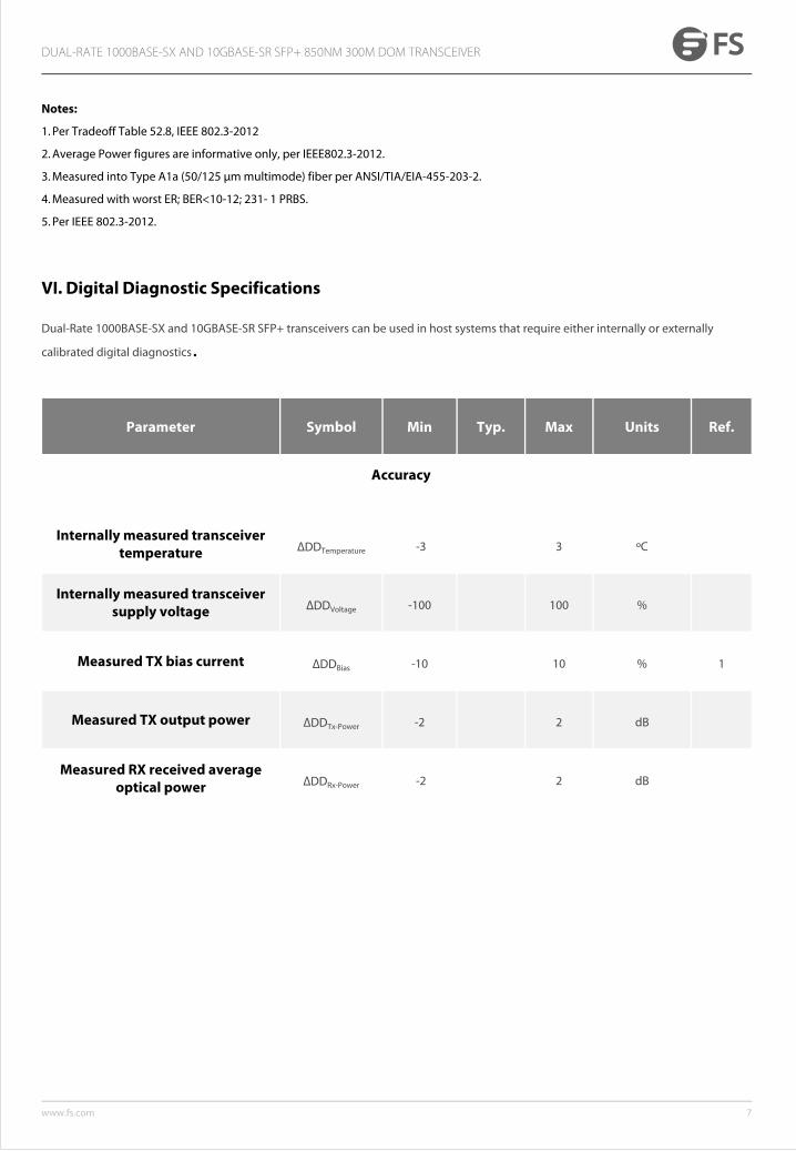
Parameter Symbol Min Typ. Max Units Ref.
Accuracy
Internally measured transceiver temperature ∆DDTemperature -3 3 ºC
Internally measured transceiver supply voltage ∆DDVoltage -100 100 %
Measured TX bias current ∆DDBias -10 10 % 1
Measured TX output power ∆DDTx-Power -2 2 dB
Measured RX received average optical power ∆DDRx-Power -2 2 dB
VI. Digital Diagnostic Specifications
DUAL-RATE 1000BASE-SX AND 10GBASE-SR SFP+ 850NM 300M DOM TRANSCEIVER
Notes:
1. Per Tradeoff Table 52.8, IEEE 802.3-2012
2. Average Power figures are informative only, per IEEE802.3-2012.
3. Measured into Type A1a (50/125 μm multimode) fiber per ANSI/TIA/EIA-455-203-2.
4. Measured with worst ER; BER<10-12; 231- 1 PRBS.
5. Per IEEE 802.3-2012.
Dual-Rate 1000BASE-SX and 10GBASE-SR SFP+ transceivers can be used in host systems that require either internally or externally
calibrated digital diagnostics.
8www.fs.com
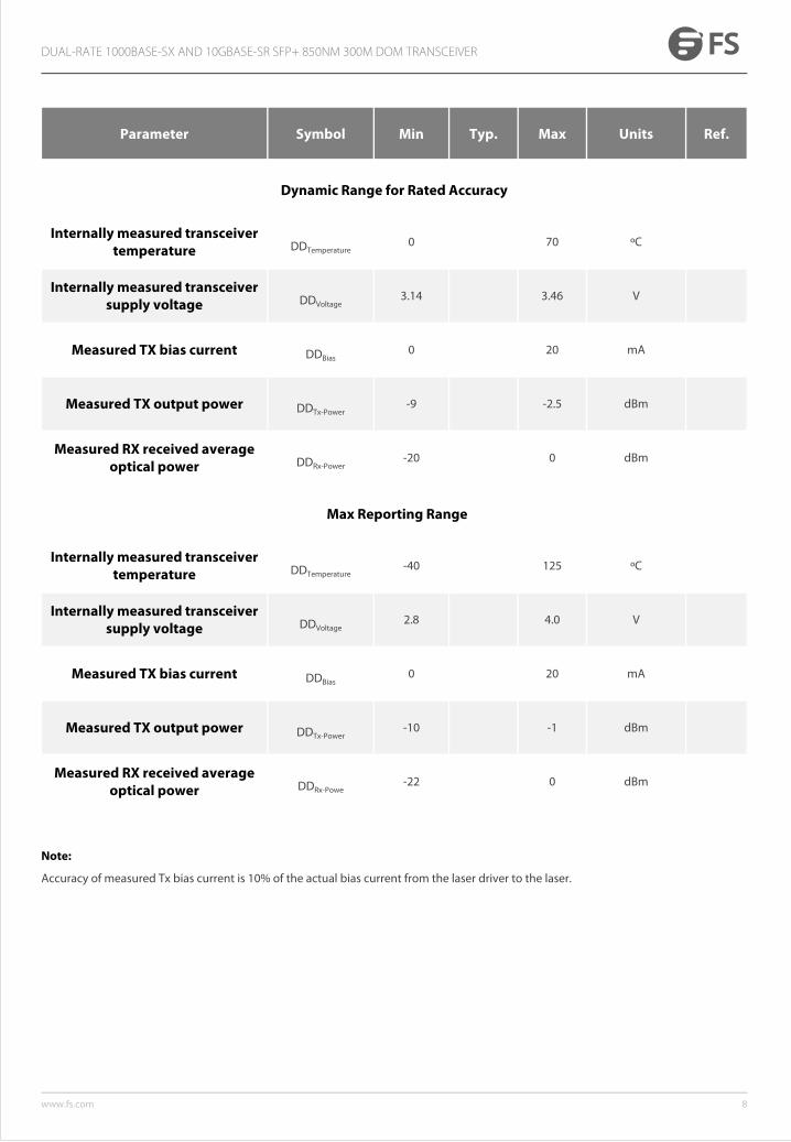
Parameter Symbol Min Typ. Max Units Ref.
Dynamic Range for Rated Accuracy
Internally measured transceiver temperature DDTemperature
0 70 ºC
Internally measured transceiver supply voltage DDVoltage
3.14 3.46 V
Measured TX bias current DDBias0 20 mA
Measured TX output power DDTx-Power-9 -2.5 dBm
Measured RX received average optical power DDRx-Power
-20 0 dBm
Max Reporting Range
Internally measured transceiver temperature DDTemperature
-40 125 ºC
Internally measured transceiver supply voltage DDVoltage
2.8 4.0 V
Measured TX bias current DDBias0 20 mA
Measured TX output power DDTx-Power-10 -1 dBm
Measured RX received average optical power DDRx-Powe
-22 0 dBm
DUAL-RATE 1000BASE-SX AND 10GBASE-SR SFP+ 850NM 300M DOM TRANSCEIVER
Note:
Accuracy of measured Tx bias current is 10% of the actual bias current from the laser driver to the laser.
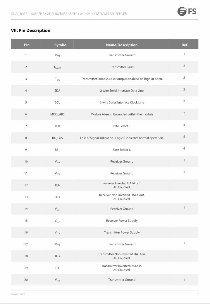
VII. Pin Description
Pin Symbol Name/Description Ref.
1 VEET Transmitter Ground 1
2 TFAULT Transmitter Fault 2
3 TDIS Transmitter Disable. Laser output disabled on high or open. 3
4 SDA 2-wire Serial Interface Data Line 2
5 SCL 2-wire Serial Interface Clock Line 2
6 MOD_ABS Module Absent. Grounded within the module 2
7 RS0 Rate Select 0. 4
8 RX_LOS Loss of Signal indication. Logic 0 indicates normal operation. 5
9 RS1 Rate Select 1. 4
10 VEER Receiver Ground 1
11 VEER Receiver Ground 1
12 RD-Receiver Inverted DATA out.
AC Coupled.
13 RD+Receiver Non-inverted DATA out.
AC Coupled.
14 VEER Receiver Ground 1
15 VCCR Receiver Power Supply
16 VCCT Transmitter Power Supply
17 VEET Transmitter Ground 1
18 TD+Transmitter Non-Inverted DATA in.
AC Coupled.
19 TD-Transmitter Inverted DATA in.
AC Coupled.
20 VEET Transmitter Ground 1
9www.fs.com
DUAL-RATE 1000BASE-SX AND 10GBASE-SR SFP+ 850NM 300M DOM TRANSCEIVER
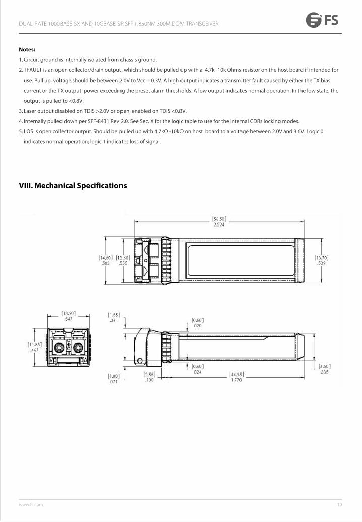
Notes:
1. Circuit ground is internally isolated from chassis ground.
2. TFAULT is an open collector/drain output, which should be pulled up with a 4.7k -10k Ohms resistor on the host board if intended for
use. Pull up voltage should be between 2.0V to Vcc + 0.3V. A high output indicates a transmitter fault caused by either the TX bias
current or the TX output power exceeding the preset alarm thresholds. A low output indicates normal operation. In the low state, the
output is pulled to <0.8V.
3. Laser output disabled on TDIS >2.0V or open, enabled on TDIS <0.8V.
4. Internally pulled down per SFF-8431 Rev 2.0. See Sec. X for the logic table to use for the internal CDRs locking modes.
5. LOS is open collector output. Should be pulled up with 4.7kΩ -10kΩ on host board to a voltage between 2.0V and 3.6V. Logic 0
indicates normal operation; logic 1 indicates loss of signal.
DUAL-RATE 1000BASE-SX AND 10GBASE-SR SFP+ 850NM 300M DOM TRANSCEIVER
VIII. Mechanical Specifications
10www.fs.com

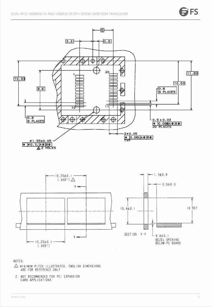
IX. PCB Layout and Bezel Recommendations
DUAL-RATE 1000BASE-SX AND 10GBASE-SR SFP+ 850NM 300M DOM TRANSCEIVER
11www.fs.com
DUAL-RATE 1000BASE-SX AND 10GBASE-SR SFP+ 850NM 300M DOM TRANSCEIVER
12www.fs.com
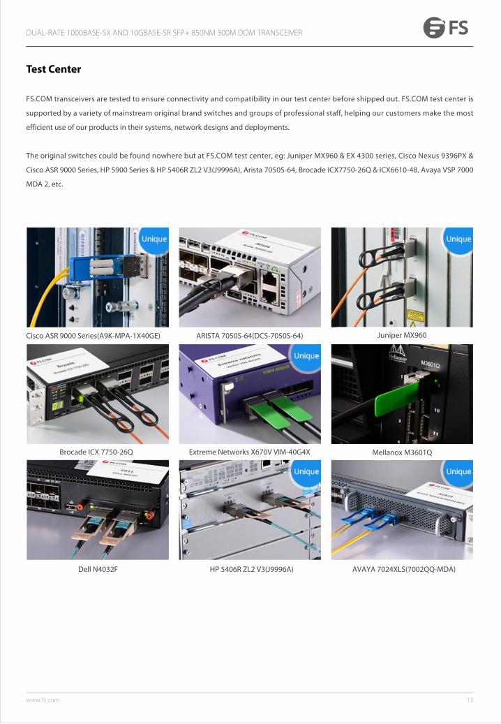
Test Center
FS.COM transceivers are tested to ensure connectivity and compatibility in our test center before shipped out. FS.COM test center is
supported by a variety of mainstream original brand switches and groups of professional staff, helping our customers make the most
efficient use of our products in their systems, network designs and deployments.
The original switches could be found nowhere but at FS.COM test center, eg: Juniper MX960 & EX 4300 series, Cisco Nexus 9396PX &
Cisco ASR 9000 Series, HP 5900 Series & HP 5406R ZL2 V3(J9996A), Arista 7050S-64, Brocade ICX7750-26Q & ICX6610-48, Avaya VSP 7000
MDA 2, etc.
Cisco ASR 9000 Series(A9K-MPA-1X40GE) ARISTA 7050S-64(DCS-7050S-64) Juniper MX960
Brocade ICX 7750-26Q Extreme Networks X670V VIM-40G4X Mellanox M3601Q
Dell N4032F HP 5406R ZL2 V3(J9996A) AVAYA 7024XLS(7002QQ-MDA)
DUAL-RATE 1000BASE-SX AND 10GBASE-SR SFP+ 850NM 300M DOM TRANSCEIVER
13www.fs.com
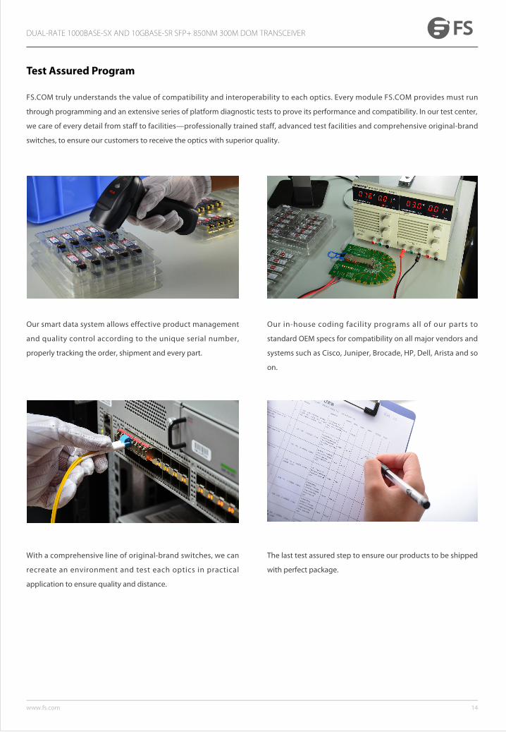
Test Assured Program
FS.COM truly understands the value of compatibility and interoperability to each optics. Every module FS.COM provides must run
through programming and an extensive series of platform diagnostic tests to prove its performance and compatibility. In our test center,
we care of every detail from staff to facilities—professionally trained staff, advanced test facilities and comprehensive original-brand
switches, to ensure our customers to receive the optics with superior quality.
Our smart data system allows effective product management
and quality control according to the unique serial number,
properly tracking the order, shipment and every part.
Our in-house coding facility programs all of our parts to
standard OEM specs for compatibility on all major vendors and
systems such as Cisco, Juniper, Brocade, HP, Dell, Arista and so
on.
With a comprehensive line of original-brand switches, we can
recreate an environment and test each optics in practical
application to ensure quality and distance.
The last test assured step to ensure our products to be shipped
with perfect package.
DUAL-RATE 1000BASE-SX AND 10GBASE-SR SFP+ 850NM 300M DOM TRANSCEIVER
14www.fs.com
15www.fs.com
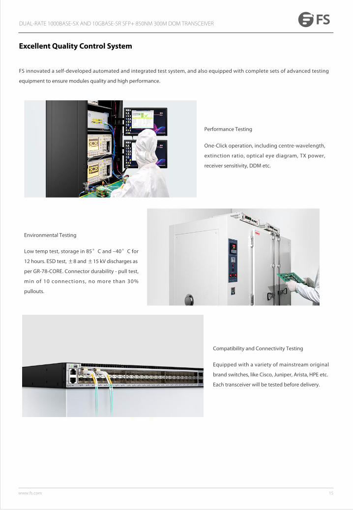
Excellent Quality Control System
FS innovated a self-developed automated and integrated test system, and also equipped with complete sets of advanced testing
equipment to ensure modules quality and high performance.
Performance Testing
One-Click operation, including centre-wavelength,
extinction ratio, optical eye diagram, TX power,
receiver sensitivity, DDM etc.
Environmental Testing
Low temp test, storage in 85°C and –40°C for
12 hours. ESD test, ±8 and ±15 kV discharges as
per GR-78-CORE. Connector durability - pull test,
min of 10 connections, no more than 30%
pullouts.
Compatibility and Connectivity Testing
Equipped with a variety of mainstream original
brand switches, like Cisco, Juniper, Arista, HPE etc.
Each transceiver will be tested before delivery.
DUAL-RATE 1000BASE-SX AND 10GBASE-SR SFP+ 850NM 300M DOM TRANSCEIVER
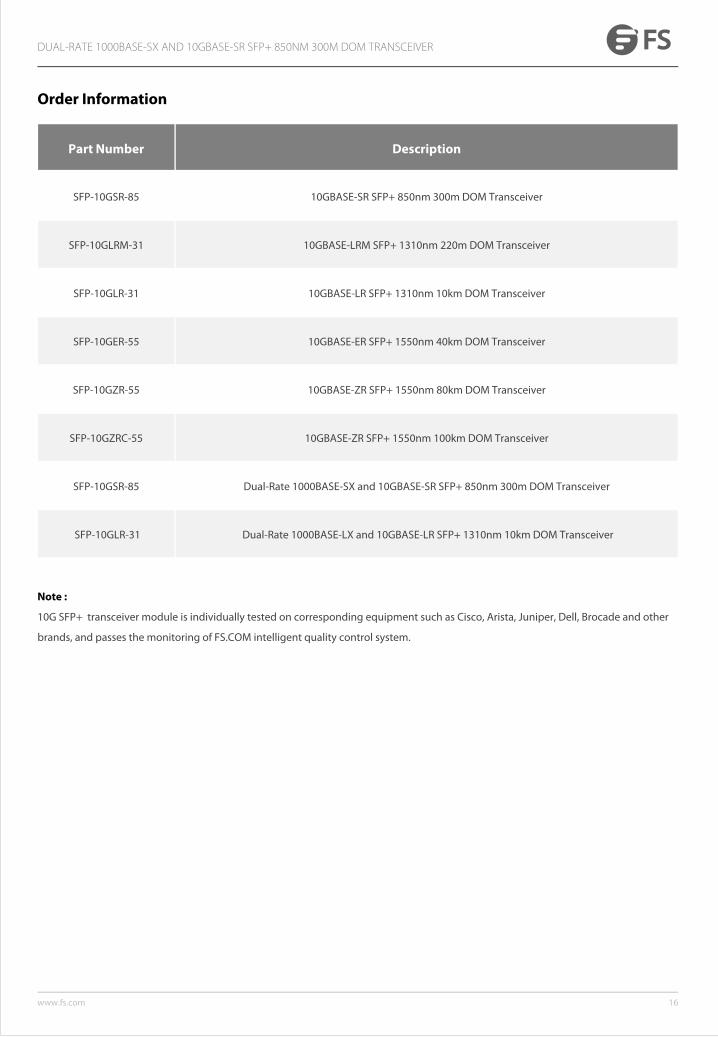
Order Information
Part Number Description
SFP-10GSR-85 10GBASE-SR SFP+ 850nm 300m DOM Transceiver
SFP-10GLRM-31 10GBASE-LRM SFP+ 1310nm 220m DOM Transceiver
SFP-10GLR-31 10GBASE-LR SFP+ 1310nm 10km DOM Transceiver
SFP-10GER-55 10GBASE-ER SFP+ 1550nm 40km DOM Transceiver
SFP-10GZR-55 10GBASE-ZR SFP+ 1550nm 80km DOM Transceiver
SFP-10GZRC-55 10GBASE-ZR SFP+ 1550nm 100km DOM Transceiver
SFP-10GSR-85 Dual-Rate 1000BASE-SX and 10GBASE-SR SFP+ 850nm 300m DOM Transceiver
SFP-10GLR-31 Dual-Rate 1000BASE-LX and 10GBASE-LR SFP+ 1310nm 10km DOM Transceiver
Note :
10G SFP+ transceiver module is individually tested on corresponding equipment such as Cisco, Arista, Juniper, Dell, Brocade and other
brands, and passes the monitoring of FS.COM intelligent quality control system.
DUAL-RATE 1000BASE-SX AND 10GBASE-SR SFP+ 850NM 300M DOM TRANSCEIVER
16www.fs.com


![Cisco Small Form-Factor Pluggable (SFP) トラン …SFP トランシーバ モジュール[光ファイバ LC コネクタ] 1000BASE-T SFP トランシーバ モジュール [RJ-45](https://static.fdocuments.us/doc/165x107/5fa24c6121d8c8099547a531/cisco-small-form-factor-pluggable-isfpi-fff-sfp-fffff-ffffff.jpg)