DTT - Snap-On Industrial Brands · • Pull on a wrench handle—do not push—when tester is...
24
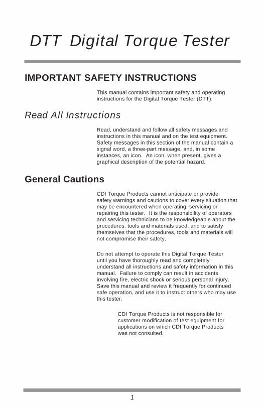
DTT DIGITAL TORQUE TESTER 2503-F-DTT 25 - 250 FT.LB. 0.0O TGT TORQUE: 250 FIRST PEAK FT-LB MAIN MENU SETUP STORE DATA: 25
Transcript of DTT - Snap-On Industrial Brands · • Pull on a wrench handle—do not push—when tester is...

DTTDIGITAL TORQUE TESTER
2503-F-DTT25 - 250 FT.LB.
0.0OTGT TORQUE: 250FIRST PEAK
FT-LB
MAIN MENU SETUP STORE
DATA: 25

Table of Contents
Important Safety Instructions ..................................................................................DTT System Components .............................................................................................Introduction ...................................................................................................................Functional Description ..................................................................................................Specifications ...............................................................................................................Transducer Range and Display Resolutions ..........................................................Setup ....................................................................................................................
Mounting .......................................................................................................Tester Set-up ................................................................................................
Tests ....................................................................................................................Quick Check Mode ........................................................................................Audit Mode ....................................................................................................Data Offload ..................................................................................................
145689
10101112131621
IMPORTANT SAFETY INSTRUCTIONSThis manual contains important safety and operatinginstructions for the Digital Torque Tester (DTT).
Read All InstructionsRead, understand and follow all safety messages andinstructions in this manual and on the test equipment.Safety messages in this section of the manual contain asignal word, a three-part message, and, in someinstances, an icon. An icon, when present, gives agraphical description of the potential hazard.
General CautionsCDI Torque Products cannot anticipate or providesafety warnings and cautions to cover every situation thatmay be encountered when operating, servicing orrepairing this tester. It is the responsibility of operatorsand servicing technicians to be knowledgeable about theprocedures, tools and materials used, and to satisfythemselves that the procedures, tools and materials willnot compromise their safety.
Do not attempt to operate this Digital Torque Testeruntil you have thoroughly read and completelyunderstand all instructions and safety information in thismanual. Failure to comply can result in accidentsinvolving fire, electric shock or serious personal injury.Save this manual and review it frequently for continuedsafe operation, and use it to instruct others who may usethis tester.
1
DTT Digital Torque Tester
CDI Torque Products is not responsible forcustomer modification of test equipment forapplications on which CDI Torque Productswas not consulted.

General Safety
WARNING
Improper use can cause breakage.• Read instructions before operating.• Follow manufacturer’s instructions, safety
precautions, and specifications when operatingtools.
Broken equipment can cause injury.
Flying particles can be discharged when applying torque.Users and bystanders must wear safety goggles.Flying particles can cause injury.
Risk of entanglement.• Keep body parts away from rotating parts.• Wear a protective hair covering to contain long
hair and prevent contact with moving parts.• Do not overreach. Keep proper footing and
balance at all times.Entanglement can cause injury.
Torque Tester Safety
WARNING• Be sure ratings for all components, including,
adaptors, extensions, drivers and sockets, matchor exceed the torque being applied.
• Do not use this instrument with power switch OFF. Always turn power switch ON so torque values aredisplayed.
• Be sure the capacity of the DTT matches orexceeds each application before performing aprocedure.
• Pull on a wrench handle—do not push—when testeris mounted horizontally. Adjust stance to prevent apossible fall.
• Do not use extensions, such as a pipe, on awrench handle.
• Fully engage the direction lever in the correctposition when using ratchets.
2
DTT Digital Torque Tester
• Do not turn the power switch ON with a torque instrument engaged to tester transducer.

• Never attempt to test an impact tool or pulse typetool on this instrument.
• Mount the DTT securely to a heavy bench, wall orother support structure before applying torque.
• Do not use the DTT if it makes unusual noises,has loose parts, or shows any other sign ofdamage. Have repairs performed at an AuthorizedService Center before use.
• Do not use chipped, cracked, or damaged socketsand accessories.
• Do not remove any labels. Replace any damagedlabel.
AC Adapter Safety
Risk of electric shock and fire.• Do not allow conductive objects to come in
contact with terminals. 120 or 220 volts present atadapter terminals.
• For indoor use only. Do not expose adapter to rain or snow. Do not use in damp locations.
• Replace defective cord immediately. Return toqualified service center for replacement.
• Do not use any other type of adapter. Using an adapter not specifically designed for this unit maydamage tester.
• Do not use an extension cord with adapter.• Do not use a damaged adapter.• Do not disassemble adapter. • Do not attempt to connect two adapters together. • Do not operate adapter with damaged cord or
plug. Replace immediately.• Do not operate adapter after it is dropped,
receives a sharp blow or damaged. Take theadapter to an Authorized Service Center.
• Unplug adapter from outlet before maintenance orcleaning. Turning off tester is not adequate toavoid hazard.
• Read all instructions and safety messages onbattery and adapter before use.
Electric shock or fire can cause injury.
SAVE THESE INSTRUCTIONS
3
WARNING
DTT Digital Torque Tester

4
DTT Digital Torque Tester
DTT System Components
A — DTT
B — AC Adapter
C — Battery Pack
D — USB Cable
AC/DC transformer, Voltage Output: 9VDC, Current 1.66A
Battery holder with 6 AA Battery cells
A
D
C
B
Figure 1: Digital Torque Tester System Components

IntroductionUse the portable DTT to test “click” type torque wrenches(adjustable and preset), torque screwdrivers, dial indicatingand electronic wrenches.
The tester features a swivel-neck LCD display withselectable English or Metric units of measure. 11 modelsare available, ranging from 10-100 IN OZ to 60-600 FT LB.
The DTT displays torque values using a built-in straingagedtransducer with an accuracy of ±0.5% of indicated test valuefrom 10% to 100% of rated capacity, in clockwise (CW) andcounter-clockwise (CCW) directions.
Torque ValuesCapture and display torque values in one of fourselectable modes:
• DIAL / ELECT (Peak Hold) — Captures and displays the highest torque applied
(CW or CCW) until reset. Use to check dial indicatingand electronic torque wrenches.
5
DTT Digital Torque Tester
CLICK ADJUST (First Peak) •— Responds to the drop-off in torque caused by the
“click” of an adjustable wrench. FIRST PEAK torqueis measured, captured and displayed (CW or CCW)just prior to the drop-off, even if click torque issubsequently exceeded.
CLICK PRESET (First Peak) •— Responds to the drop-off in torque caused by the
“click” of a preset wrench. FIRST PEAK torque ismeasured, captured and displayed (CW or CCW)just prior to the drop-off, even if click torque issubsequently exceeded.
• SCREWDRIVER (Peak Hold)— Captures and displays the highest torque applied
(CW or CCW) until reset. Use to check torquelimiting screwdrivers.
This manual contains general information.Operating features and specifications maychange without notice. CDI Torque makes noclaims regarding the suitability of the informationin this manual for diverse user applications.
Power SourceThe power source for the DTT is the supplied AC Adapter.The tester can also be operated with the use of the 6 AABattery Pack that accompanies the tester.
A — DisplayA four digit TFT display for torque readings.
B — Mounting PlatePlate for securing tester to mounting surface. Usefour 1/4” diameter bolts.
6
DTT Digital Torque Tester
Functional Description
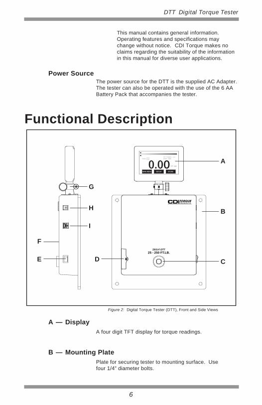
Figure 2: Digital Torque Tester (DTT), Front and Side Views
A
B
G
H
I
CDE
F2503-F-DTT
25 - 250 FT.LB.
0.0OTGT TORQUE: 250FIRST PEAK
FT-LB
MAIN MENU SETUP STORE
DATA: 25
C — TransducerFemale square drive.
D — Battery Access Battery Pack housing panel. Remove Phillips screwto access Battery Pack.
E — Power Switch Rocker switch turns power to tester on and off.
F — Audible Alert Signal sounds momentarily when:• Power to tester is initiated,
• Target Torque is reached.
G — Swivel Holds the display for view from any angle.
H — AC Adapter Jack Receptacle (9VDC @ 1.66A max) for continuous ACoperation.
I — USB Jack Receptacle for uploading torque data to externalcomputer.
7
DTT Digital Torque Tester
• Anytime a button pressed, and

SpecificationsDisplayLCD on swivel neck
Display Specifications
Accuracy±0.5% of indicated test value from 10% to 100% of ratedcapacity
Units of MeasurementFT-LB, IN-LB, IN-OZ, KG-CM, Nm and cNm
8
DTT Digital Torque Tester
Size: 4.7 inchResolution: 480 (RGB) X 272
Operating Temperature0 – 50°C (32 – 122°F)
Storage-20 – 70°C (-4 – 158°F)
DimensionsWidthHeight 15.2”Depth 2.5”
Weight11 lbs
BatterySix 1.5V (AA), replaceable
AC AdapterInput 100 ~ 240VAC (50-60 Hz) Output 9VDC, 1.66A
Integral TransducerFull bridge strain gage,350 ohms, 1500 µE, 3mV/V F.S., 3.3V excitation
10.0”
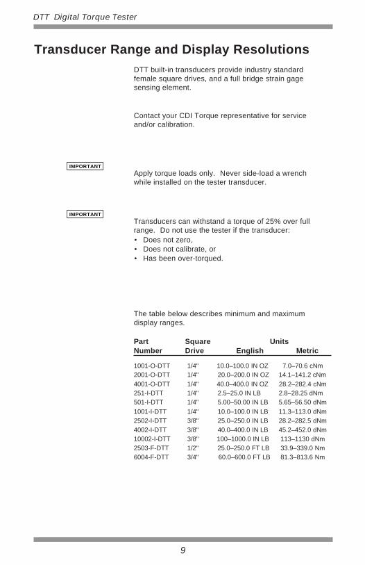
Transducer Range and Display ResolutionsDTT built-in transducers provide industry standardfemale square drives, and a full bridge strain gagesensing element.
Apply torque loads only. Never side-load a wrenchwhile installed on the tester transducer.
Transducers can withstand a torque of 25% over fullrange. Do not use the tester if the transducer:• Does not zero,• Does not calibrate, or• Has been over-torqued.
Contact your CDI Torque representative for serviceand/or calibration.
The table below describes minimum and maximumdisplay ranges.
Part Square UnitsNumber Drive English Metric
501-I-DTT 1/4" 5.00–50.00 IN LB 5.65–56.50 dNm1001-I-DTT 1/4" 10.0–100.0 IN LB 11.3–113.0 dNm
1001-O-DTT 1/4" 10.0–100.0 IN OZ 7.0–70.6 cNm
4001-O-DTT 1/4" 40.0–400.0 IN OZ 28.2–282.4 cNm251-I-DTT 1/4" 2.5–25.0 IN LB 2.8–28.25 dNm
2001-O-DTT 1/4" 20.0–200.0 IN OZ 14.1–141.2 cNm
2502-I-DTT 3/8" 25.0–250.0 IN LB 28.2–282.5 dNm4002-I-DTT 3/8" 40.0–400.0 IN LB 45.2–452.0 dNm10002-I-DTT 3/8" 100–1000.0 IN LB 113–1130 dNm2503-F-DTT 1/2" 25.0–250.0 FT LB 33.9–339.0 Nm6004-F-DTT 3/4" 60.0–600.0 FT LB 81.3–813.6 Nm
9
DTT Digital Torque Tester
IMPORTANT
IMPORTANT

SetupMounting
Vertical mounting on a wall or heavy pillar is preferred formost wrench and tool testing as shown in the illustrationbelow. Use four 1/4” diameter bolts (torqued to 10 FT LB)to insure a secure mount. The DTT can also be mountedvertically to a horizontal surface using a right anglebracket.
A – Mounting Screw (4)B – Right Angle Bracket
10
DTT Digital Torque Tester
Figure 3: Mounting, Dimensions and Right Angle Bracket
A
B8.87”
8.87”
2503-F-DTT25 - 250 FT.LB.
Mount the DTT to a sturdy support before use. Torquetesting procedures may involve hundreds of pounds ofload. Be sure to consider counterweight of the mount toaccommodate torque testing operations and testingfixtures. Allow enough room around and below the mountfor the wrenches or testing fixtures being used.
Tester Setup
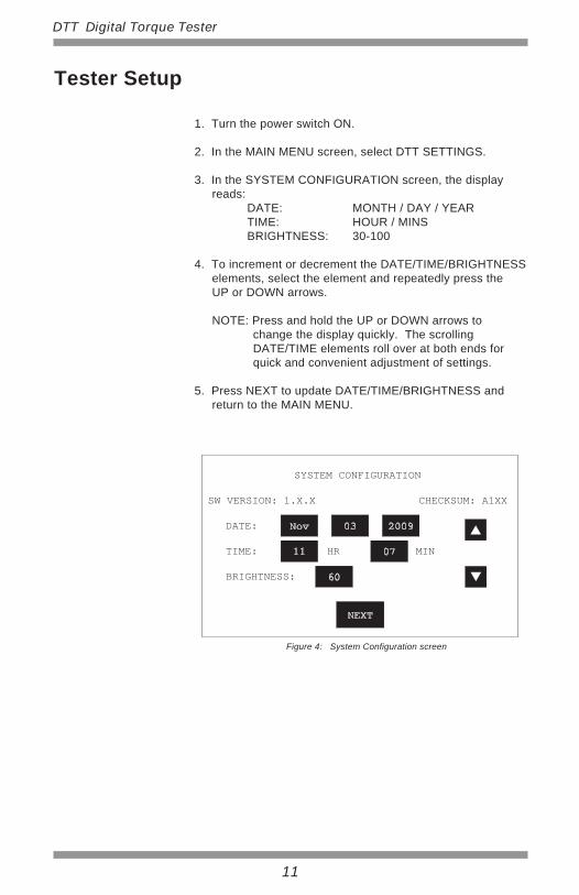
1. Turn the power switch ON.
2. In the MAIN MENU screen, select DTT SETTINGS.
3. In the SYSTEM CONFIGURATION screen, the displayreads: DATE: MONTH / DAY / YEAR TIME: HOUR / MINS BRIGHTNESS: 30-100
4. To increment or decrement the DATE/TIME/BRIGHTNESSelements, select the element and repeatedly press theUP or DOWN arrows.
NOTE: Press and hold the UP or DOWN arrows tochange the display quickly. The scrolling DATE/TIME elements roll over at both ends forquick and convenient adjustment of settings.
5. Press NEXT to update DATE/TIME/BRIGHTNESS andreturn to the MAIN MENU.
11
DTT Digital Torque Tester
SYSTEM CONFIGURATION
SW VERSION: 1.X.X CHECKSUM: A1XX
DATE:
TIME: HR MIN
BRIGHTNESS:
Nov 03 2009
11 07
60
NEXT
Figure 4: System Configuration screen

TestsTesting Wrenches
• To avoid damage, be sure the DTT model being usedis capable of handling the torque being applied.
• Always position a torque wrench within 15° ofperpendicular to the display housing (Figure 5).
Testing Wrenches 1. Prepare tester for use. For additional information
refer to TESTER SETUP.
NOTE: DTT will ZEROTARE automatically when powerswitch is turned ON.
2. In the MAIN MENU screen, select TEST.
NOTE: The operator can return to the MAIN MENUat any step during this procedure by pressingthe MAIN button.
12
DTT Digital Torque Tester
IMPORTANT
3. In the SELECT WRENCH TYPE screen, select oneof the following options:
CLICK ADJUST
CLICK PRESET
DIAL / ELEC
SCREWDRIVER
Figure 5: Wrench Position, Perpendicular to Tester
2503-F-DTT
0.0OTGT TORQUE: 250FIRST PEAK
FT-LB
MAIN MENU SETUP STORE
DATA: 25
WARNINGDo not turn the power switch ON with a torqueinstrument engaged to tester transducer.
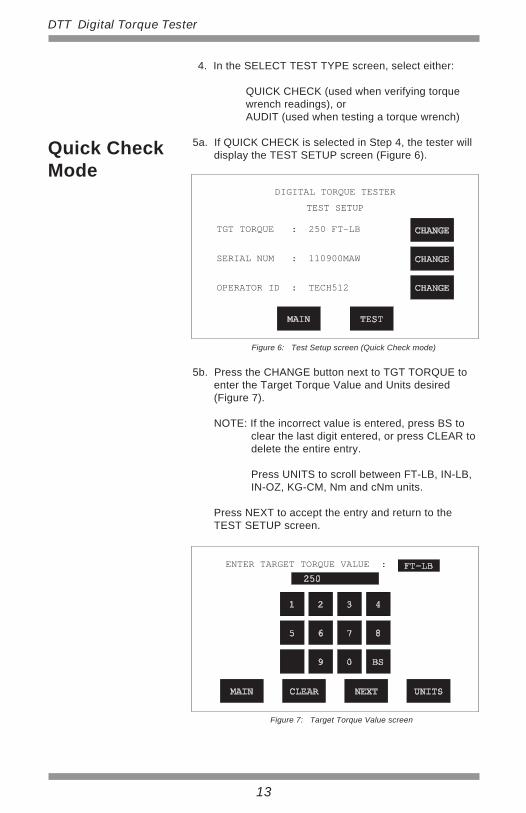
4. In the SELECT TEST TYPE screen, select either:
QUICK CHECK (used when verifying torque wrench readings), or AUDIT (used when testing a torque wrench)
5a. If QUICK CHECK is selected in Step 4, the tester willdisplay the TEST SETUP screen (Figure 6).
5b. Press the CHANGE button next to TGT TORQUE toenter the Target Torque Value and Units desired(Figure 7).
NOTE: If the incorrect value is entered, press BS toclear the last digit entered, or press CLEAR todelete the entire entry.
Press UNITS to scroll between FT-LB, IN-LB,IN-OZ, KG-CM, Nm and cNm units.
Press NEXT to accept the entry and return to theTEST SETUP screen.
13
DTT Digital Torque Tester
ENTER TARGET TORQUE VALUE :
MAIN CLEAR NEXT UNITS
Figure 7: Target Torque Value screen
FT-LB250
1 2 3 4
5 6 7 8
9 0 BS
Quick CheckMode
DIGITAL TORQUE TESTER
TEST SETUP
MAIN TEST
CHANGE
CHANGE
CHANGE
Figure 6: Test Setup screen (Quick Check mode)
TGT TORQUE : 250 FT-LB
SERIAL NUM : 110900MAW
OPERATOR ID : TECH512

5c. Press the CHANGE button next to SERIAL NUM toenter a wrench Serial Number if required (Figure 8).
NOTE: The WRENCH S/N screen can be changedfrom Numerical (Figure 8) to Alphabetical(Figure 9) Mode and vice versa by pressingthe 0-9 or A-Z key respectively.
If the incorrect value is entered, press BS toclear the last digit entered, or press CLEAR todelete the entire entry.
The WRENCH S/N screen can be left blank Ifthe Serial Number information is not required.
A 12 digit long alpha-numeric combination canbe entered in the WRENCH S/N screen.
Press NEXT to accept the entry and return to theTEST SETUP screen.
14
DTT Digital Torque Tester
ENTER WRENCH S/N:
CLEAR NEXT
Figure 8: Wrench Serial Number screen (Numeric Mode)
5 6 7 8
1 2 3 4
A-Z 9 0 BS
110900
ENTER WRENCH S/N :
CLEAR NEXT
Figure 9: Wrench Serial Number screen (Alphabetical Mode)
Q W E R T Y U I O P
A S D F G H J K L
0-9 Z X C V B N M BS
110900MAW

5d. Press the CHANGE button next to OPERATOR ID toenter an Operator Identification number if required(Figure 10).
NOTE: The OPERATOR ID screen can be changedfrom Alphabetical (Figure 10) to Numerical(Figure 11) Mode and vice versa by pressingthe A-Z or 0-9 key respectively.
If the incorrect value is entered, press BS toclear the last digit entered, or press CLEAR todelete the entire entry.
The OPERATOR ID screen can be left blank Ifthe Operator Identification is not required.
An 8 digit long alpha-numeric combination canbe entered in the OPERATOR ID screen.
Press NEXT to accept the entry and return to theTEST SETUP screen.
15
DTT Digital Torque Tester
ENTER OPERATOR ID:
CLEAR NEXT
Figure 10: Operator ID screen (Alphabetical Mode)
Q W E R T Y U I O P
A S D F G H J K L
0-9 Z X C V B N M BS
TECH
ENTER OPERATOR ID:
CLEAR NEXT
Figure 11: Operator ID screen (Numeric Mode)
5 6 7 8
1 2 3 4
A-Z 9 0 BS
TECH512

5e. Press the TEST button to accept all entries anddisplay the QUICK CHECK test screen (Figure 12).
NOTE: The operator can return to the TEST SETUPscreen by pressing the SETUP button.
5f. Install the wrench on the transducer and apply torque.
5g. Press STORE to save torque measurements in theinternal memory. Torque measurements can be offloaded to a PC using the USB cable. Foradditional information refer to Data Offload.
6a. If AUDIT is selected in Step 4, the tester will displaythe TEST SETUP screen (Figure 13).
16
DTT Digital Torque Tester
0.0OTGT TORQUE: 250FIRST PEAK
FT-LB
MAIN MENU SETUP STORE
DATA: 25
Figure 12: Quick Check test screen
Audit Mode
DIGITAL TORQUE TESTER
TEST SETUP
MAIN TEST
CHANGE
CHANGE
CHANGE
Figure 13: Test Setup screen (Audit Mode)
WRENCH SIZE : 250 FT-LB
SERIAL NUM : 110900MAW
OPERATOR ID : TECH512

17
DTT Digital Torque Tester
6b. Press the CHANGE button next to WRENCH SIZE toenter the Full Scale torque and Units of the wrenchbeing calibrated (Figure 14).
NOTE: If the incorrect value is entered, press BS toclear the last digit entered, or press CLEAR todelete the entire entry.
Press UNITS to scroll between FT-LB, IN-LB,IN-OZ, KG-CM, Nm and cNm units.
Press NEXT to accept the entry and return to theTEST SETUP screen.
NOTE: For information on how to update SERIAL NUM, and OPERATOR ID;
please refer to Steps 5c & 5d.
Press TEST to accept all entries.
ENTER WRENCH MAX RANGE :
MAIN CLEAR NEXT UNITS
Figure 14: Wrench Max Range screen
FT-LB250
1 2 3 4
5 6 7 8
9 0 BS

18
DTT Digital Torque Tester
6c. The tester will prompt user to set wrench to 20% ofFull Scale (Figure 15).
For example: If WRENCH MAX RANGE (Step 6b) is entered as 250 FT-LB, the DTT will prompt user to set wrench to 50 FT-LB.
Press NEXT.
6d. The display will change to the 20% test screen(Figure 16).
Install the wrench on the transducer.
The screen will display a test counter which indicatesthe number of times the user must apply torque at the20% setting:
TEST 1 of 3 TEST 2 of 3 TEST 3 of 3
Apply torque until the wrench reaches 50 FT-LB. Then press STORE to advance the test counter.Repeat procedure until counter reaches 3 of 3.
PLEASE SET WRENCH TO 50 FT-LB
NEXT
Figure 15: Wrench Set prompt screen
0.0OTGT TORQUE: 50FIRST PEAK
FT-LB
MAIN MENU STORE
Figure 16: 20% torque test screen
TEST 1 OF 3DATA: 1
19
DTT Digital Torque Tester
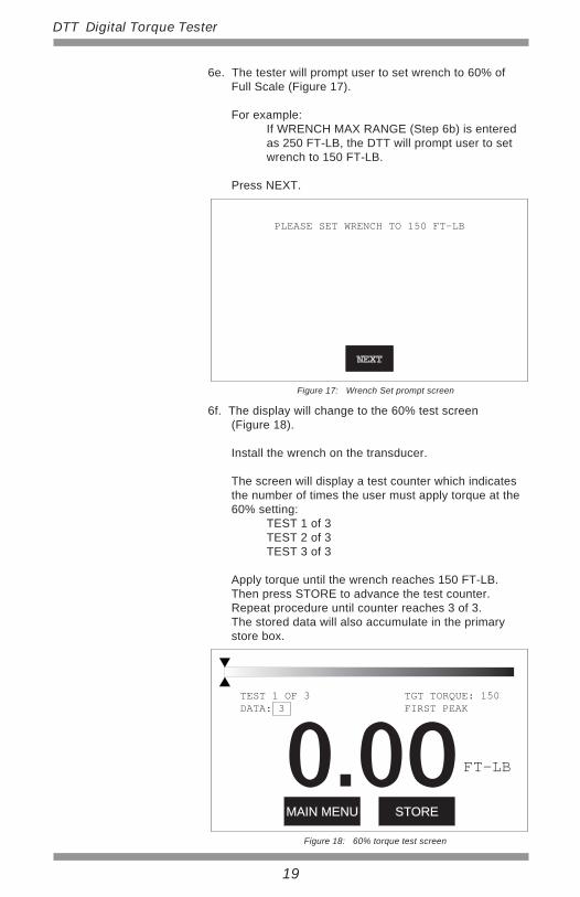
6e. The tester will prompt user to set wrench to 60% ofFull Scale (Figure 17).
For example: If WRENCH MAX RANGE (Step 6b) is entered as 250 FT-LB, the DTT will prompt user to set wrench to 150 FT-LB.
Press NEXT.
6f. The display will change to the 60% test screen(Figure 18).
Install the wrench on the transducer.
The screen will display a test counter which indicatesthe number of times the user must apply torque at the60% setting: TEST 1 of 3 TEST 2 of 3 TEST 3 of 3
Apply torque until the wrench reaches 150 FT-LB. Then press STORE to advance the test counter.Repeat procedure until counter reaches 3 of 3.The stored data will also accumulate in the primarystore box.
PLEASE SET WRENCH TO 150 FT-LB
NEXT
Figure 17: Wrench Set prompt screen
0.0OTGT TORQUE: 150FIRST PEAK
FT-LB
MAIN MENU STORE
Figure 18: 60% torque test screen
TEST 1 OF 3DATA: 3
20
DTT Digital Torque Tester
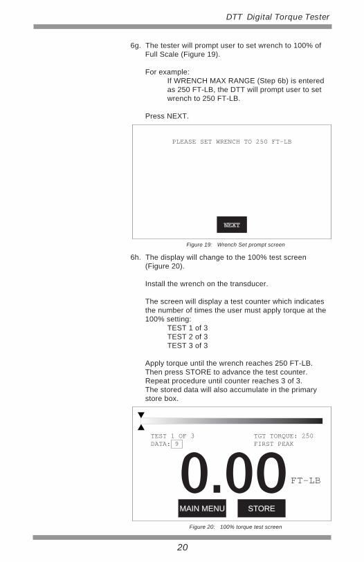
6g. The tester will prompt user to set wrench to 100% ofFull Scale (Figure 19).
For example: If WRENCH MAX RANGE (Step 6b) is entered as 250 FT-LB, the DTT will prompt user to set wrench to 250 FT-LB.
Press NEXT.
6h. The display will change to the 100% test screen(Figure 20).
Install the wrench on the transducer.
The screen will display a test counter which indicatesthe number of times the user must apply torque at the100% setting: TEST 1 of 3 TEST 2 of 3 TEST 3 of 3
Apply torque until the wrench reaches 250 FT-LB. Then press STORE to advance the test counter.Repeat procedure until counter reaches 3 of 3.The stored data will also accumulate in the primarystore box.
PLEASE SET WRENCH TO 250 FT-LB
NEXT
Figure 19: Wrench Set prompt screen
0.0OTGT TORQUE: 250FIRST PEAK
FT-LB
MAIN MENU STORE
Figure 20: 100% torque test screen
TEST 1 OF 3DATA: 9
21
DTT Digital Torque Tester
6i . At the end of the test sequence, the tester will return tothe TEST SETUP screen in order to begin a new testsequence. To continue the test sequence in the CCWdirection, press TEST.
6j. Stored torque measurements can be offloaded to a PCusing the USB cable. For additional information referto Data Offload.
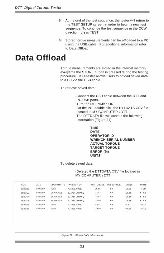
Torque measurements are stored in the internal memoryeverytime the STORE button is pressed during the testingprocedure. DTT tester allows users to offload saved datato a PC via the USB cable.
To retrieve saved data:
-Connect the USB cable between the DTT andPC USB ports.
-Turn the DTT switch ON. -On the PC, double click the DTTDATA.CSV file
located in MY COMPUTER \ DTT. -The DTTDATA file will contain the following
information (Figure 21):
TIME DATE OPERATOR ID WRENCH SERIAL NUMBER ACTUAL TORQUE TARGET TORQUE ERROR (%) UNITS
To delete saved data:
-Deleted the DTTDATA.CSV file located in MY COMPUTER \ DTT
Data Offload
TIME DATE OPERATOR ID WRENCH S/N ACT TORQUE TGT TORQUE ERR(%) UNITS
16:28:36 03/03/09 TEST A23456789012 35.66 50 -28.68 FT-LB
16:29:13 03/03/09 SNAPON12 123ASFGHJKLQ 35.67 50 -28.65 FT-LB
16:29:14 03/03/09 SNAPON12 123ASFGHJKLQ 35.67 50 -28.66 FT-LB
16:29:15 03/03/09 SNAPON12 123ASFGHJKLQ 35.66 50 -28.68 FT-LB
16:44:46 03/03/09 TEST A23456789012 48.4 50 -3.2 FT-LB
16:45:23 03/03/09 TEST A23456789012 29.56 50 -40.89 FT-LB
Figure 21: Stored Data Information

Made in USA with US and Global Components
For Warranty Claims, Contact CDI Torque Products
LIMITED WARRANTY
The DTT Digital Torque Tester is backed by a one yearwarranty. This warranty covers manufacturer defects andworkmanship. The warranty excludes misuse, abuse andnormal wear and tear. Exclusion is not allowed in somestates and may not apply. This warranty gives you specificlegal rights, and you may have other rights, which varyfrom state to state.
FORM 20-2344-CDI02/10 REV NC
19220 San Jose Ave.City of Industry, CA 91748Phone: 626-965-0668Fax: 626-965-2410Email: [email protected]: www.cditorque.com