DTS Migration to Digital Microwave Digital Fundamentals Testing Applications Making the Change.
69
DTS Migration to Digital Microwave Digital Fundamentals Testing Applications Making the Change
-
Upload
rudy-lammert -
Category
Documents
-
view
225 -
download
2
Transcript of DTS Migration to Digital Microwave Digital Fundamentals Testing Applications Making the Change.

DTS
Migration to Digital Microwave
Digital Fundamentals
Testing Applications
Making the Change
DTS Dover Telecommunication Services, Inc. © 2002 All rights reserved
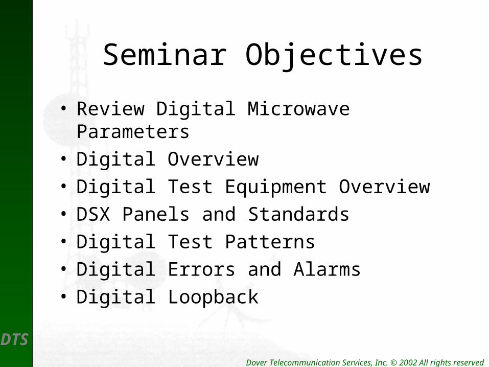
Seminar Objectives
• Review Digital Microwave Parameters• Digital Overview• Digital Test Equipment Overview• DSX Panels and Standards• Digital Test Patterns• Digital Errors and Alarms• Digital Loopback

DTS Dover Telecommunication Services, Inc. © 2002 All rights reserved
Single VF Channel
3825 HZOut-of-Band Signaling Tone
E & M (-20 dBmØ)
Usable VoiceBandwidth3.1 K Flat

DTS Dover Telecommunication Services, Inc. © 2002 All rights reserved
Baseband Elements
• The Analog Basebands consist of – Baseband amplifiers– Baseband bridges– Roofing filters– Group converters– Pilot stop filters– Orderwire and Service Channels– Alarm and control devices

DTS Dover Telecommunication Services, Inc. © 2002 All rights reserved
Analog and Digital SignalProcessing
• An analog baseband is the composite of all – Voice and HF tones– Noise in each channel– Cumulative system noise
• Analog means Amplify

DTS Dover Telecommunication Services, Inc. © 2002 All rights reserved
Digital Interfaces
• T1 – DS3 Interface– Interconnection into a digital radio– Conform to ANSI standards– Use Standard DSX Panels
• Layout
• Wiring protocol
• Making a cross-connect

DTS Dover Telecommunication Services, Inc. © 2002 All rights reserved
North American Digital Hierarchy
DS0 4KHz – 1DS0 64Kb/s
DS1 24 – DS0 1.544Mb/s
DS3
(STS 1)
672 – DS0 45.736Mb/s
(51.840Mb/s)
OC3 - Optical
(STS 3) – Elec.
2016 – DS0 155.220Mb/s
OC12 8064 – DS0 622.08Mb/s
OC 48 32,256 – DS0 2488.32Mb/s
OC192 129,024 – DS0 9953.28Mb/s

DTS Dover Telecommunication Services, Inc. © 2002 All rights reserved
RF Carriers
• Radio Frequencies (RF) are defined as:– Periodic waves capable of traveling thru space.– Waveforms that meet the conditions of
Maxwell’s Equations.– Always periodic electro-magnetic wave fronts.– Always consist of three core elements . . .

DTS Dover Telecommunication Services, Inc. © 2002 All rights reserved
Modulation
• RF carriers exist as CW with no external modulation – variation.
• To Modulate is to vary, such as:– Change Amplitude –AM– Change Frequency – FM– Change Phase – Ø

DTS Dover Telecommunication Services, Inc. © 2002 All rights reserved
CW Wave
TEK492PGM
REFLEVEL 0 DBM
FREQUENCY6.535 GHzCEN DBM
SPAN/DIV 10 MHz
10 DB/VERTICALDISPLAY
30 DBRF
ATTENUATION
3.0 — 7.1FREQ
RANGE
INT 1 MHzRESOLUTIONBANDWIDTH
0
-10
-20
-30
-40
-50
-60
-70
-80

DTS Dover Telecommunication Services, Inc. © 2002 All rights reserved
FM Modulation
• When a carrier is frequency modulated the following occur:– The frequency changes – The amplitude in the fundamental carrier
changes.– Multiple sidebands now have carrier power– For Example . . .

DTS Dover Telecommunication Services, Inc. © 2002 All rights reserved
Bessel Null Plot

DTS Dover Telecommunication Services, Inc. © 2002 All rights reserved
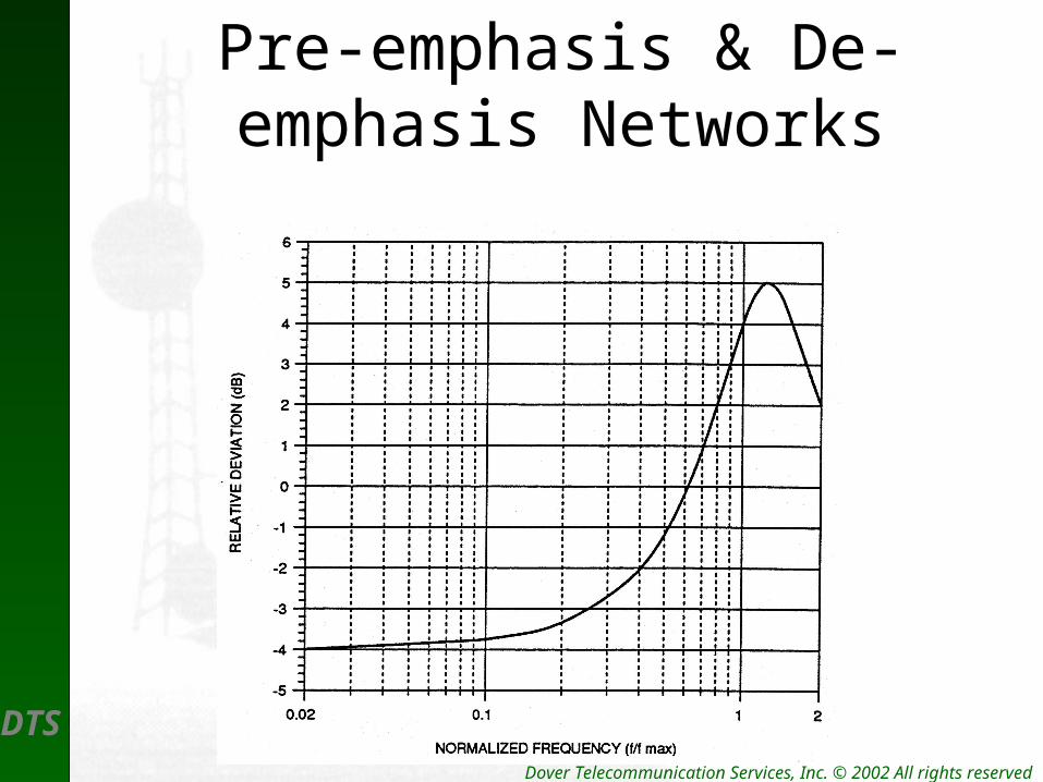
Baseband to RF
• After signal combination the following occur:– Passage through Pre-emphasis– Modulation of RF carrier
• FM Typical
• PM Possible
DTS Dover Telecommunication Services, Inc. © 2002 All rights reserved
Pre-emphasis & De-emphasis Networks

DTS Dover Telecommunication Services, Inc. © 2002 All rights reserved
Modulator Analog Radio
75
-25 dBm
FrequencySynth sizer
BBTEST
IN
30 dB
-55 dBm
AntennaMonitor-30 dBc
+30 dBm(+24 dBmOptional)
WGCMR 137
Antenna Coupling Unit
-20 dBm
HF Signal
Pre-emphasis
Composite TLP
ModulationHere
AntennaCouplingCarrier
Osc.

DTS
Digital Microwave
Digital Systems
Digital Transmitters
Digital Receivers

DTS Dover Telecommunication Services, Inc. © 2002 All rights reserved
Typical System Configuration

DTS Dover Telecommunication Services, Inc. © 2002 All rights reserved
Digital Transmitter
• Digital Transmitters contain the following:– Pulse input equipment (I/O Interface)
• Pulse Conversion• TDM Mux for multiple signals • LBO
– Band Pass Filters – BPF– RF Carrier Source Oscillators– I and Q splitters – Summing Amplifiers– Power Amplifiers

DTS Dover Telecommunication Services, Inc. © 2002 All rights reserved
Digital TransmitterBlock

DTS Dover Telecommunication Services, Inc. © 2002 All rights reserved
QPSK Modulator Diagram

DTS Dover Telecommunication Services, Inc. © 2002 All rights reserved
Digital Modulation
• Modulating Steps– AMI/B8ZS to NRZ Conversion
– Data Line Splits• I-- Lines
• Q– Lines (Quadrature 90° phase shift)
– Mixing with Source Oscillator
– Summing Combined RF Signal
– FCC Mask Filter
– Example ..\Microwave Course\QAMGIF.gif

DTS Dover Telecommunication Services, Inc. © 2002 All rights reserved
Signal Processing
• DS1 Signals arrive at Modem (I/O) as– AMI– B8ZS– 1.544mb/s / T1
• DS3 Signals arrive at Modem (I/O) as– B3ZS– 44.736mb/s / DS3
• OC3 Signals arrive at HLM on Fiber @– 155.220mb/s

DTS Dover Telecommunication Services, Inc. © 2002 All rights reserved
Signals Change
• Signals are converted to NRZ signals
• Signals are passed thru a LPF
DTS Dover Telecommunication Services, Inc. © 2002 All rights reserved
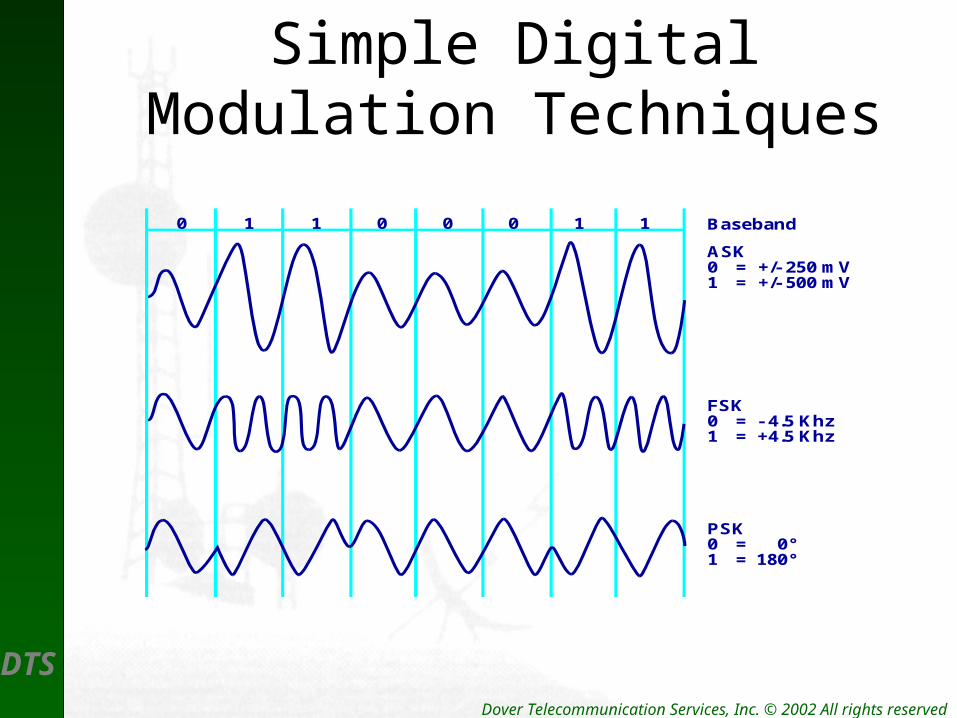
Simple Digital Modulation Techniques
0 1 1 0 0 0 1 1 Baseband
ASK0 = +/- 250 mV1 = +/- 500 mV
FSK0 = - 4.5 Khz1 = +4.5 Khz
PSK0 = 0°1 = 180°

DTS Dover Telecommunication Services, Inc. © 2002 All rights reserved
4-Level Digital Modulation
0 1 1 0 0 0 1 1 Baseband
ASK00 = +/- 125 mV01 = +/- 250 mV10 = +/- 375 mV11 = +/- 500 mV
FSK00 = - 4.5 Khz01 = -2.8 Khz10 = +2.8 Khz11 = +4.5 Khz
PSK00 = 45°01 = 135°10 = 315°11 = 225°
-2.8 +2.8 -4.5 +4.5

DTS Dover Telecommunication Services, Inc. © 2002 All rights reserved
QPSK PatternQ
00100
01
1
0111
I
DTS Dover Telecommunication Services, Inc. © 2002 All rights reserved
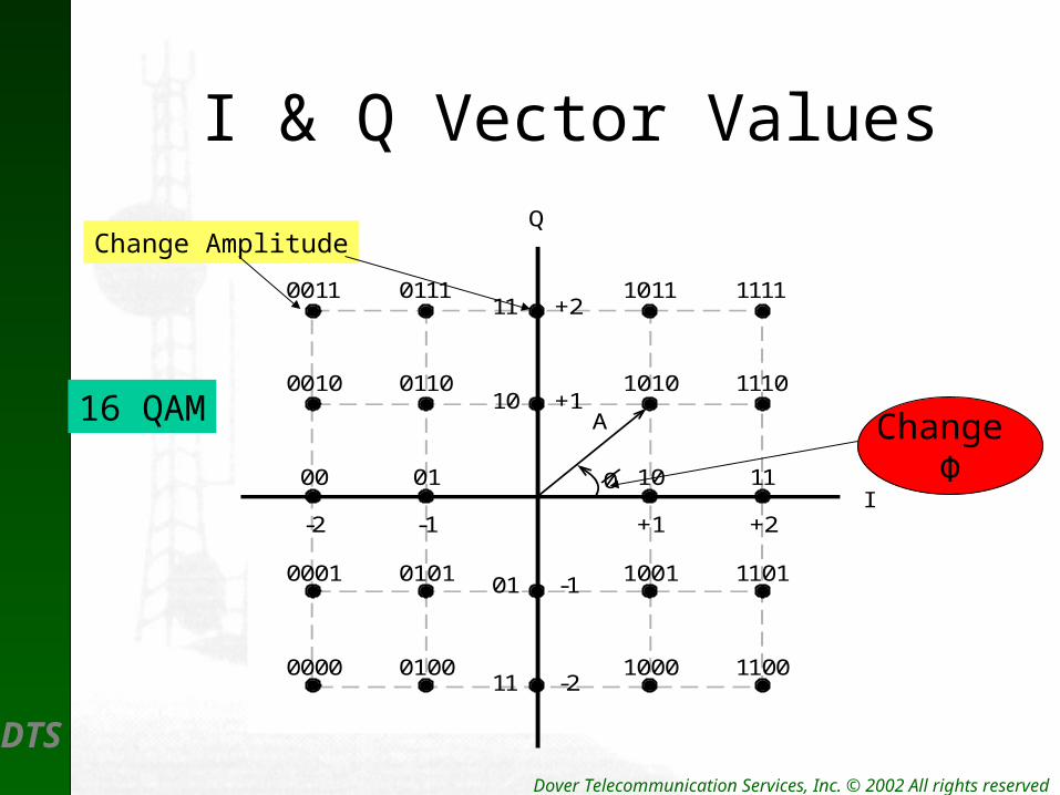
I & Q Vector ValuesQ
I
0011 0111 1011 1111
0010 0110 1010 1110
0001 0101 1001 1101
0000 0100 1000 1100
00 01 10 11
A
0
-2 -1 +1 +2
11 +2
10 +1
01 -1
11 -2
16 QAM
Change Amplitude
Change Φ

DTS Dover Telecommunication Services, Inc. © 2002 All rights reserved
Phase & Carrier at 64 QAM
1
2
3
4
5
6
7
8
9
10
11
12
13
14
15
16
17
18
19
20
21
22
23
24
25
26
27
28
29
30
31
32
33
34
35
36
37
38
39
40
41
42
43
44
45
46
47
48
49
50
51
52
53
54
55
56
57
58
59
60
61
62
63
64
+7L
+5L
+3L
+L
-L
-3L
-5L
-7L
-7L -5L -3L -L +L +3L +5L +7L I
Q
DTS Dover Telecommunication Services, Inc. © 2002 All rights reserved
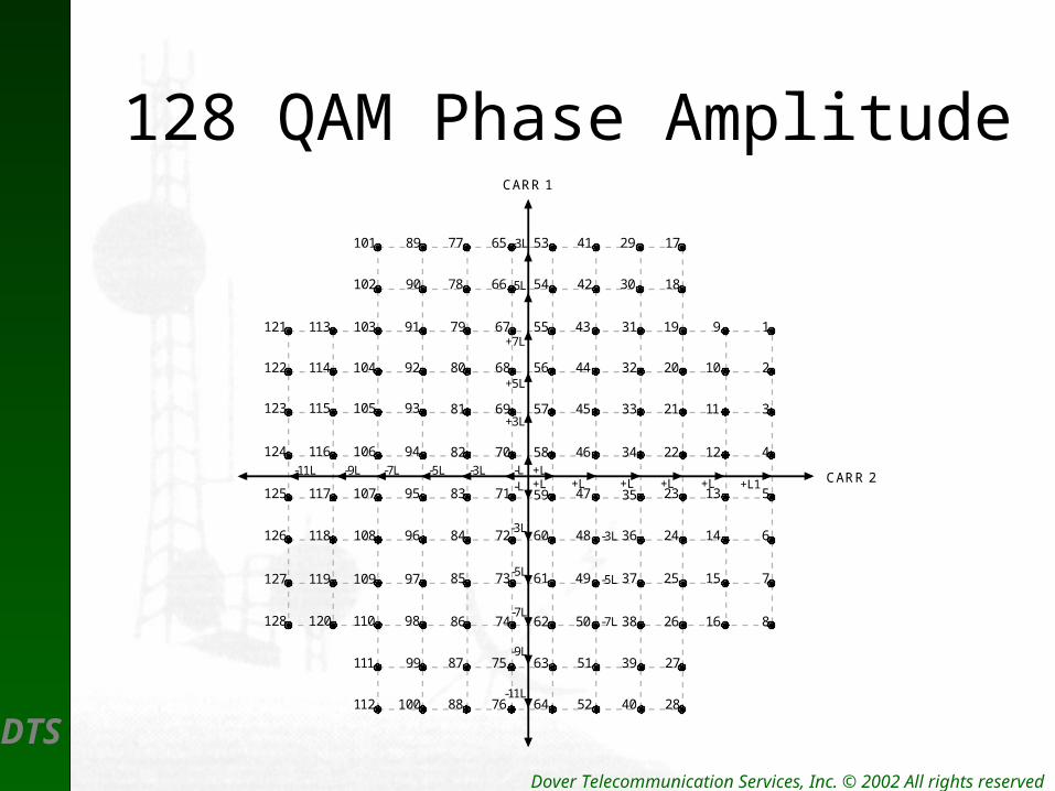
128 QAM Phase AmplitudeCARR 1
CARR 2
1
2
3
4
5
6
7
8
9
10
11
12
13
14
15
16
19
20
21
22
23
24
25
26
31
32
33
34
35
36
37
38
43
44
45
46
47
48
49
50
55
56
57
58
59
60
61
62
67
68
69
70
71
72
73
74
79
80
81
82
83
84
85
86
+7L
+5L
+3L
+L-L
-3L
-5L
-7L
-7L -5L+L +L +L +L1
27
28
39
40
51
52
63
64
75
76
-3L
-5L
17
18
29
30
41
42
53
54
65
66
-3L
-5L
87
88
77
78
99
100
111
112
89
90
101
102
91103113
92104114
93105115
94106116
95107117
96108118
97109119
98110120
121
122
123
124
125
126
127
128-7L
-9L
-11L
-L-3L-9L-11L+L +L

DTS Dover Telecommunication Services, Inc. © 2002 All rights reserved
Bandwidth Efficiency
128 QAM

DTS
Microwave PowerAmplifiers
Amplifier Characteristics
Amplifier Distortion
Amplifiers as Oscillators

DTS Dover Telecommunication Services, Inc. © 2002 All rights reserved
Microwave Power Amplifiers
ATPC – Controls the Power outputRSL at Receiver drives ATPC

DTS
Microwave Receivers
Receiver Elements
Receiver Process

DTS Dover Telecommunication Services, Inc. © 2002 All rights reserved
Receiver Characteristics
• Receiver Selectivity
• Receiver Sensitivity
• The RSL Curve
• The Digital Carrier– Carrier Recovery– Timing Recovery

DTS Dover Telecommunication Services, Inc. © 2002 All rights reserved
Conventional Receiver
Most Receivers use IF sections

DTS Dover Telecommunication Services, Inc. © 2002 All rights reserved
Direct Conversion Receiver
Typical of MDR 6000 RadioBandwidth restricted

DTS Dover Telecommunication Services, Inc. © 2002 All rights reserved
Digital IF Sections
• The digital IF section performs:– Equalization– Interference suppression– Signal stability

DTS Dover Telecommunication Services, Inc. © 2002 All rights reserved
Radio Link Multi-path Characteristics

DTS Dover Telecommunication Services, Inc. © 2002 All rights reserved
Multi-path Distortion

DTS Dover Telecommunication Services, Inc. © 2002 All rights reserved
Carrier Recovery
• Threshold for 10-6 BER Rate
• Ability to detect incoming carrier– Effects of SSBSC Modulation– Local Source Oscillator – Locking signal– Pulse Timing Recovery
DTS Dover Telecommunication Services, Inc. © 2002 All rights reserved
Data Recovery
• Receivers detect and reconstruct original data – Block Coding
• Reed-Solomon
• Galois
• Hamming
– Convolution Code

DTS Dover Telecommunication Services, Inc. © 2002 All rights reserved
Error Detection
• There is a difference between Detecting an Error and Correcting an Error– Common errors detected are:
• CRC
• BCH
• Bit Errors

DTS Dover Telecommunication Services, Inc. © 2002 All rights reserved
Forward Error Correction(FEC)
• Common methods of detecting and Correcting data bit errors are:– BCH used in most SCADA applications– Reed-Solomon
• A Block Code
• Uses Parity checks
DTS Dover Telecommunication Services, Inc. © 2002 All rights reserved
Reed-Solomon Codes
• Capable of Correcting a Single Error Symbol.• Similar to BCH Error Codes• Used in Harris Constellation Radio• Is Considered a Block Code

DTS Dover Telecommunication Services, Inc. © 2002 All rights reserved
The Eye-Pattern
• True status of pulse recovery
• Determines jitter in timing circuit
• Determines Inter-symbol-Interference (ISI)

DTS Dover Telecommunication Services, Inc. © 2002 All rights reserved
Eye Pattern

DTS Dover Telecommunication Services, Inc. © 2002 All rights reserved
Single Sweep of Eye Pattern

DTS Dover Telecommunication Services, Inc. © 2002 All rights reserved
The Terminal ACU
• The Antenna Coupling Unit – Circulates the TX and RX Signals– Isolate the TX from the RX– Protects amplifiers and filters

DTS Dover Telecommunication Services, Inc. © 2002 All rights reserved
Antenna Coupling
DTS Dover Telecommunication Services, Inc. © 2002 All rights reserved
Network Management
• Digital networks are often managed by a central system
• Internet Management Protocol (SNMP)

DTS
Testing Applications
Testing T1 Circuits
Test Set Operation
Test Patterns
Error Reporting

DTS Dover Telecommunication Services, Inc. © 2002 All rights reserved
DSX1 Panel
• Purpose of the DSX1 Panel– Interconnection
• Terminates a Single Piece of Equipment
• Cross-Connects Two Pieces of Equipment
– Monitor Access• TLP = -20DB
• Level is dBdsx
432ΩIsolation

DTS Dover Telecommunication Services, Inc. © 2002 All rights reserved
Terminating T1 Spans
Test Equipment terminates the circuit as follows:
Bridge = > 1000Ω
Term = 100Ω
DSXMON = 100Ω/Gain
Signal Level typically:
6v P-P = 0dBdsx
ZL= 100 Ω

DTS Dover Telecommunication Services, Inc. © 2002 All rights reserved
LBO in Radio

DTS Dover Telecommunication Services, Inc. © 2002 All rights reserved
T1 Configurations4 – T1 Radio
T1#1
T1#4
LBO
T1#2
T1#3
M12I/O
Each T1Has LBOSetting

DTS Dover Telecommunication Services, Inc. © 2002 All rights reserved
The 28 T1 RadioConstellation

DTS Dover Telecommunication Services, Inc. © 2002 All rights reserved
DS3 Microwave Interface
• Up to 3 DS3 Signals can be Connected • Data Rate can Interface to OC3• Fiber and Copper make a Connection• DS3-DSX Panel Connections• The DS3 Copper Connection –RG59

DTS Dover Telecommunication Services, Inc. © 2002 All rights reserved
Typical DS3 Interface
M13 Mux
M13 Mux
M13 Mux
DS3
DS3
DS3
Radio optioned for 1 to 3 DS3 Channels

DTS Dover Telecommunication Services, Inc. © 2002 All rights reserved
Constellation DS3Terminal

DTS Dover Telecommunication Services, Inc. © 2002 All rights reserved
Digital Overview
• T1 Framing
• T1 Line Codes
• T1 Timing
• T1 Signal Levels

DTS Dover Telecommunication Services, Inc. © 2002 All rights reserved
Network Elements
• DSX Panels – T1 and DS3 Electrical
• T1 Devices– Channel Banks– NIU’s to Telco Network– CSU – FT1

DTS Dover Telecommunication Services, Inc. © 2002 All rights reserved
DS3 Overview
• Channelized Vs Unchannelized
• M13 Mux– Low Speed– High Speed
• Electrical Interface – DS3 & STS
• Optical Interface – T1 to OC-192

DTS Dover Telecommunication Services, Inc. © 2002 All rights reserved
Test Equipment Setup
1ST
What to Test

DTS Dover Telecommunication Services, Inc. © 2002 All rights reserved
Test Signals
Test Pattern REPLACES Traffic on T1Span . . . INTRUSIVE

DTS Dover Telecommunication Services, Inc. © 2002 All rights reserved
Common Test Patterns
• All Zeros – AMI/B8ZS Provisioning
• All Ones – Copper – Max 1’s
• 3 in 24 – Stress to AMI Circuits– Minimum 1’s density 1/8– 15 Consecutive 0’s
• QRSS – Voice = average 1’s

DTS Dover Telecommunication Services, Inc. © 2002 All rights reserved
T1 Errors
• 4 types of T1 errors:– BPV Errors, always on Copper– CRC Errors, always in ESF Framing– Framing Errors, 100% Accurate– BIT Errors – Out of Service Test
DTS Dover Telecommunication Services, Inc. © 2002 All rights reserved
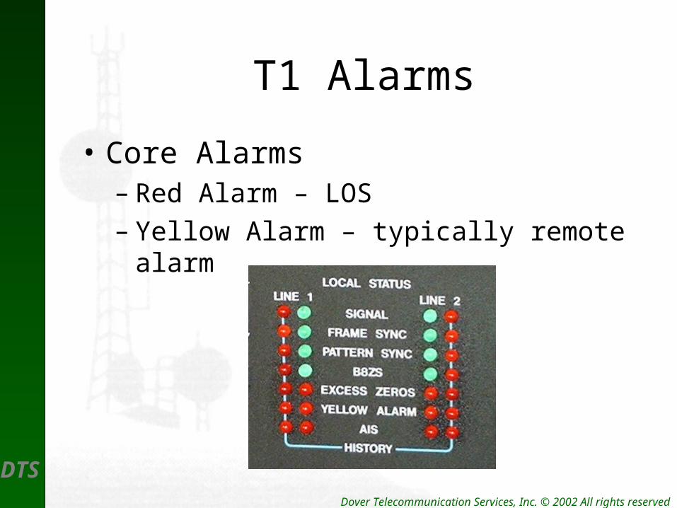
T1 Alarms
• Core Alarms– Red Alarm – LOS– Yellow Alarm – typically remote alarm
DTS Dover Telecommunication Services, Inc. © 2002 All rights reserved
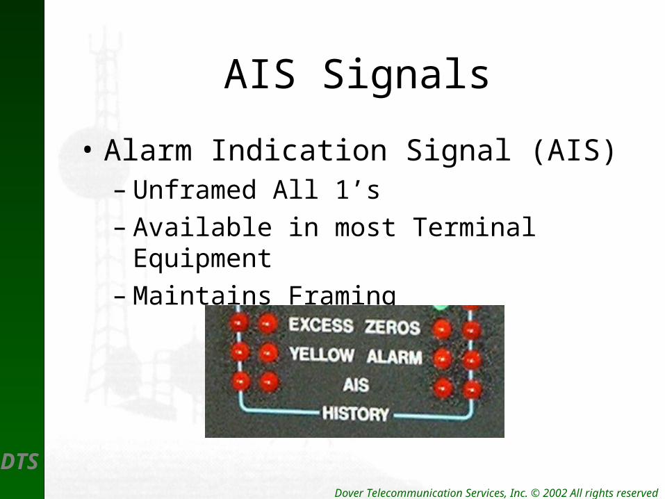
AIS Signals
• Alarm Indication Signal (AIS)– Unframed All 1’s– Available in most Terminal Equipment– Maintains Framing

DTS Dover Telecommunication Services, Inc. © 2002 All rights reserved
T1 Loopbacks
• Available in most Terminal Equipment– Coastcom Mux– Microwave Radio– Digital Cross-connect (DCS)– CSU– NIU