
dtr optimal gwarancja EJDRUK 09 08 2017 detektor2...
20
rev:12.07.17 MAINTENANCE MANUAL WARRANTY CARD AIR HANDLING UNIT OPTIMAL Below documentation shall be kept by user! In case of not following the conditions of this document, the warranty expires. EN
Transcript of dtr optimal gwarancja EJDRUK 09 08 2017 detektor2...

rev:
12
.07
.17
MAINTENANCE MANUALWARRANTY CARD
AIR HANDLING UNIT
OPTIMAL
Below documentation shall be kept by user!In case of not following the conditions of this document, the warranty expires.
EN
rev:
12
.07
.17
3
3
3
6
6
6
6
7
8
9
9
9
10
10
11
12
13
14
15
15
16
17
20
1. GENERAL INFORMATION................................................................................
1.1. Purpose................................................................................................
1.2. Technical specification..............................................................................
2. ASSEMBLY.................................................................................................
2.1. Required exploitation conditions..................................................................
2.2. Pre-assemblyrequirements.........................................................................
2.3. Unit location..........................................................................................
2.4. Assembly of condensaation dreinage system....................................................
2.5. Connecting to ventilation...........................................................................
2.6. Connecting to power grid...........................................................................
3. STARTING THE UNIT.....................................................................................
3.1. General remarks.....................................................................................
3.2. Connecting contol panel...........................................................................
3.3. Starting the unit.....................................................................................
3.4. Usage and maintenance...........................................................................
3.5. Summer mode (OPTIMAL 400 bypass/600 bypass).............................................
3.6. Working with carbon monoxide sensor (option)...............................................
4. EXPLOITATION RECOMMENDATION..................................................................
5. ELECTRICAL CONNECTION - AUTOMATION MODULE..............................................
5.1. Assembly and disassembly of automation module.............................................
5.2. Connection scheme................................................................................
6. AC2800 DIGITAL CONTROLLER.......................................................................
7. WARRANTY..............................................................................................
CONTENTS
Op
tim
al 4
00
/60
0
EN

rev:
12.0
7.1
7
198mm
3400m /h3600m /h
0-450 Pa0-340 Pa
48,8 kg 49,8 kg
838 mm x 631 mm x 583 mmDimensions
Air flow (100 Pa)
Diameter of ventilating connectors
Disposal compression
Max power consumption
Heat recovery efficiency
Power supply voltage
Motor rational speed
Type of motor bearing
Acoustic pressure
Insulation class
Internationl protection rating
Weight
roller bearing
max. 52dB(A)/1m
I
IP40
max. 53dB(A)/1m
1400 rpm 1650 rpm
up to 95%
OPTIMAL400 BYPASS
OPTIMAL600 BYPASS
OPTIMAL air handling unit is destined for air exchange in residential buildings.
The purpose of the unit is to bring fresh air from the outside and to siphon off used air from the rooms
with simultaneous heat recovery.
1. GENERAL INFORMATION
1.1. Purpose
1.2. Technical specification
Op
tima
l 40
0/6
00
min. 20W / max. 150W min. 20W / max. 250W
230 VAC / 50Hz
EN

rev:
12.0
7.1
7
2. Flow efficiency characteristics OPTIMAL 400 bypass
Optimal 400 BYPASS
3v [m /h]
Op
tim
al 4
00
/60
0
1. Nominal dimensions of OPTIMAL
583570
375175
838725
198178
478 625
EN

rev:
12.0
7.1
7
3. Flow efficiency characteristics OPTIMAL 600 bypass
Optimal 600 BYPASS
3v [m /h]
Op
tima
l 40
0/6
00
EN
rev:
12.0
7.1
7
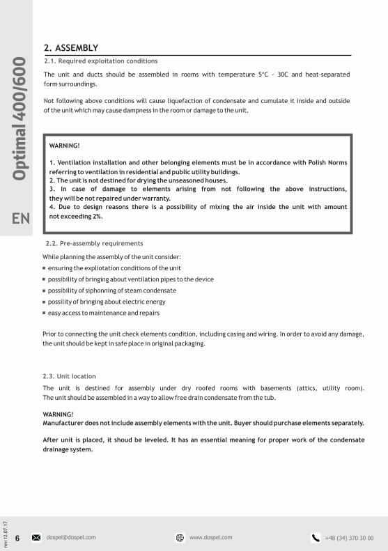
2. ASSEMBLY
2.1. Required exploitation conditions
The unit and ducts should be assembled in rooms with temperature 5°C - 30C and heat-separated
form surroundings.
Not following above conditions will cause liquefaction of condensate and cumulate it inside and outside
of the unit which may cause dampness in the room or damage to the unit.
2.2. Pre-assembly requirements
While planning the assembly of the unit consider:
- ensuring the expliotation conditions of the unit
- possibility of bringing about ventilation pipes to the device
- possibility of siphonning of steam condensate
- possility of bringing about electric energy
- easy access to maintenance and repairs
2
WARNING!
1. Ventilation installation and other belonging elements must be in accordance with Polish Norms
referring to ventilation in residential and public utility buildings.
2. The unit is not destined for drying the unseasoned houses.
3. In case of damage to elements arising from not following the above instructions,
they will be not repaired under warranty.
4. Due to design reasons there is a possibility of mixing the air inside the unit with amount
not exceeding 2%.
Prior to connecting the unit check elements condition, including casing and wiring. In order to avoid any damage,
the unit should be kept in safe place in original packaging.
2.3. Unit location
The unit is destined for assembly under dry roofed rooms with basements (attics, utility room).
The unit should be assembled in a way to allow free drain condensate from the tub.
WARNING!
Manufacturer does not include assembly elements with the unit. Buyer should purchase elements separately.
After unit is placed, it shoud be leveled. It has an essential meaning for proper work of the condensate
drainage system.
Op
tim
al 4
00
/60
0
EN

rev:
12.0
7.1
7
2.4. Assembly of condensaation dreinage system
Steam condensation can be observed during unit's work. It is completely normal and it is not an abnormality
in working. In order to siphon out condensate the unit is equipped with stub pipe placed on the right side.
It is essental to properly connect the pipe siphoning out the condensate.
Exemplary way of conneting the pipe is shown below. The pipe should have adequate diameter to the stub-
pipe (1/2"). It shoud be bent into letter "U" and suffused with water until stabilizing its level.
Shipon should be palced around 150 mm from the unit and radius should not be less than R=30 mm.
Given measures should be taken as minimal.
Op
tima
l 40
0/6
00
4. Proper positioning of the unit. It is essential to keep level of the base
5. Exemple of pipe assembly to siphon out condensate
water level
EN
rev:
12.0
7.1
7
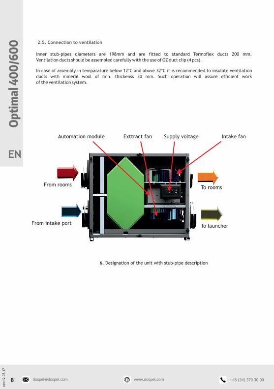
Inner stub-pipes diameters are 198mm and are fitted to standard Termoflex ducts 200 mm.
Ventilation ducts should be assembled carefully with the use of OZ duct clip (4 pcs).
In case of assembly in temparature below 12°C and above 32°C it is recommended to insulate ventilation
ducts with mineral wool of min. thickenss 30 mm. Such operation will assure efficient work
of the ventilation system.
2.5. Connection to ventilation
Op
tim
al 4
00
/60
0
6. Designation of the unit with stub-pipe description
Automation module
From roomsTo rooms
From intake portTo launcher
Exttract fan Intake fanSupply voltage
EN

rev:
12.0
7.1
7
2.6. Conneting to power grid
Unit should be connected directly to one phase outlet 230V/50Hz in the most accessible place.
All electrical matter should be perfomed by authorized person.
WARNING!
Prior to maintenance work or repairs, unit should be disconnected from the power outlet
by pulling the plug out.
In case of damaging the wire, replacement can only be performed by authorized person.
1. Prior to starting the unit read the manual.
2. Check if there is no objects present in the ducts which may damage the unit or endanger health.
3. It is recommended to test the working mode of the unit prior to connecting it to ventilation.
3. STARTING THE UNIT
3.1. General remarks
Op
tima
l 40
0/6
00
7. Manner of conneting power cord
EN

rev:
12.0
7.1
7
WARNING!
While testing the installation follow the safety rules in order to avoid improper direction of airflow,
i.e. open chimney duct or other devices with open fire towards room.
3.2. Connecting control panel
Air handling unit is equipped with weekly controller.
Control panel is delivered with 20 m connection cord ended with plug type RJ11.
Control panel should be placed on a wall, but you should previosuly plan how to lead cord from unit to panel.
WARNING!!! Cord cannot be less than 5m long.
3.3. Starting the unit
1. Read the manual
2. See if there is no damage
3. Place unit in wanted place
4. Connect control panel
5. Connect connection cord to power grid 230 V
6. Turn on the unit using control panel ot turn on "TURBO" mode for 3 minutes
7. Check if there is air flow at the stub-pipes (WARNING! Do not put hands inside the stub-pipes
- may results in injuries!)
8. Turn off the unit using control panel
9. Unplug power cord from grid
10. Disconnect control panel from unit
11. Mount the unit in ventilation system
12. Lead control panel's cord from unit to destined mounting place
13. Mount control panel
14. Connect unit to control panel
15. Connect power cord to power grid
16. Turn on control panel and set weekly program
17. Control air intake efficiency in accordane with project
Once all above is performed, the unit can be used.
Op
tim
al 4
00
/60
0
EN
rev:
12.0
7.1
7
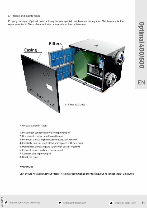
Properly mounted Optimal does not require any special maintenance during use. Maintenance is the
replacement of air filters. Visual indication informs about filter replacement.
3.4. Usage and maintenance
Filter exchaange in steps:
1. Disconnect connection cord from power grid
2. Disconnect control panel from the unit
3. Dismount the casing by unscrewing butterfly screws
4. Carefully take out used filters and replace with new ones
5. Mount back the casing and screw with butterfly screws
6. Connect power cord and control panel
7. Connect unit to power grid
8. Reset the timer
WARNING!!!
Unit should not work without filters. It is only recommended for testing, but no longer than 10 minutes.
Op
tima
l 40
0/6
00
8. Filter exchange
Casing
Filters
EN
rev:
12.0
7.1
7
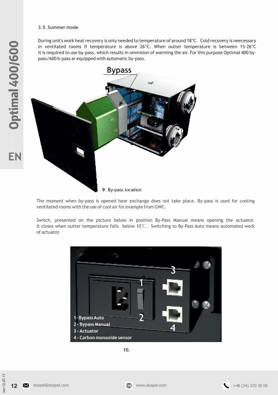
3.5. Summer mode
During unit's work heat recovery is only needed to temperature of around 18°C. Cold recovery is neecessary
in ventilated rooms if temperature is above 26°C. When outter temperature is between 15-26°C
it is required to use by-pass, which results in ommision of warming the air. For this purpose Optimal 400 by-
pass/600 b-pass ar equipped with automatic by-pass.
The moment when by-pass is opened hear exchange does not take place. By-pass is used for cooling
ventilated rooms with the use of cool air for example from GWC.
Switch, presented on the picture below in position By-Pass Manual means opening the actuator.
It closes when outter temperature falls below 10℃. Switching to By-Pass Auto means automated work
of actuator.
Op
tim
al 4
00
/60
0
9. By-pass location
10.
1- Bypass Auto
2 - Bypass Manual
3 - Actuator
4 - Carbon monoxide sensor
Bypass
EN

rev:
12.0
7.1
7
3.6. Working with carbon monoxide sensor (option)
OPTIMAL unit is designed to work with carbon monoxide sensor. Basic function of this sensor it detection
of carbon monoxide and generating alarm when excessive amount of it is detected. Sensor decreases
risk of carbon monoxide poisoning and allows to take action in life-threatening situations.
Carnon monoxide sensor should be installed in:- room with fireplace or tiled stove- room with gas burners- bathroom with warm water gas heaters- boiler house- garage or workshops
Unit working with carbon monoxide sensor results in exhaust and intake fans to work on maximum
speed. Decrease of carbon monoxide in air allows unit to return to normal operation mode.
Detailed description of carbon monoxide sensor can be found in manual.
Op
tima
l 40
0/6
00
A2
+12V
+12V
GND
Detektor CO
GND
+12V
A2
+12V
Socket RJ11
Plug RJ11com NO
Plug RJ11 Plug RJ11
External power suply 230VACPower suply 12VDC
A2
+12V +12V
GND
230VAC
+12V GNDL
Nwyjściestykowe
zaciski
zasilania 12V
com NO
wyjście
stykowe
CO Sensor
EN

rev:
12.0
7.1
7
ź Necessity of filter replacement is signaled by countdown timer via visual warning.
The filter cartridge made of polyester fabrics cannot be cleaned and must be replaced with a new one if
necessary. New filters should be ordered from the device supplier.
The time indicator of contamination of the filter counts down the time remaining until the next filter
change.
To start the countdown for the first time, press and hold the RESET button for 3 seconds.
The need to replace the filter is signaled by audible and visual signals - after the countdown is over, the digits
00 00 00 are displayed on the screen.
The signal must be reset by pressing the RESET button.
The device is equipped with a magnet and CR1130 battery.
Fan check-up
Despite of required maintenance work (cleaninf/filer exchange) dust and grase can be slowly embed inside
the fan, which can decrese its effecitivity. Fan can be cleand with cloth or soft brush. Keep caution while
cleaning not to damage fan's impeller. Do not clean with water, do not put in water! Solid dirt can be cleaned
with denaturated alcohol. Prior to placing back - dry well.
Control of condensate's stub-pipe
Stub-pipe can become dirty overtime by fixed particles brought by air. It is recommended to periodically
check (by flushing with water) stub-pipe patency. Clean if needed.
ź
ź
4. Exploitation Recommendation
ź
Unit is a part of a whole system. the system supplies fresh air and launches used air through ducts
and intake/exhaust diffusers. Air diffusers are installed in ceilings, walls, bathrooms and rooms.
They should be periodically cleaned with warm water and soap, if needed. If they were dismounted
for cleaning they should be put in the same places - they cannot be changed.
ź Control of fresh air inlet and launcher
Pollution as leafs, insects, dust, etc.) can clog air inlet which causes air flow throttling.
Check and clean air inlet at least twice a year.
Launcher installed on wall must be checked (cleaned if needed) at least once a year.
ź Duct check-up (every 5 years)
Dust and grease particles will pile up in duct despite of recommended maintenance which can decrease
effectivity of installation. Due to that fact, ducts should be cleaned/exchanged when needed.
Cleaning intake and exhaust
Op
tim
al 4
00
/60
0
EN
rev:
12.0
7.1
7
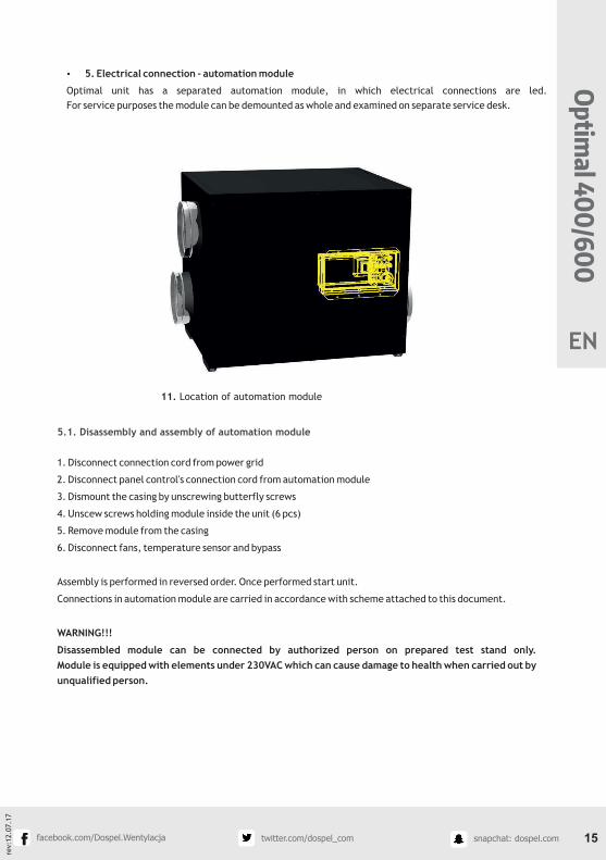
ź 5. Electrical connection - automation module
Optimal unit has a separated automation module, in which electrical connections are led.
For service purposes the module can be demounted as whole and examined on separate service desk.
1. Disconnect connection cord from power grid
2. Disconnect panel control's connection cord from automation module
3. Dismount the casing by unscrewing butterfly screws
4. Unscew screws holding module inside the unit (6 pcs)
5. Remove module from the casing
6. Disconnect fans, temperature sensor and bypass
Assembly is performed in reversed order. Once performed start unit.
Connections in automation module are carried in accordance with scheme attached to this document.
WARNING!!!
Disassembled module can be connected by authorized person on prepared test stand only.
Module is equipped with elements under 230VAC which can cause damage to health when carried out by
unqualified person.
5.1. Disassembly and assembly of automation module
Op
tima
l 40
0/6
00
11. Location of automation module
EN

rev:
12.0
7.1
7
WARNING:Electric equipment is not a household waste. Once exploitation time is over it should be disassembled
by hand with use of wrench, screwdrivers and pliers). Electric motors, automation, power supply,
steel elements and those made out of plastics should be recycled. Information where to recycle is available
at local administration offices.
Op
tim
al 4
00
/60
0
12. Connection scheme
5.2. Connection scheme
Sock
et
RJ1
1
Male
sock
et
IEC
Male
sock
et
IEC
T3,1
5A*
T3,1
5A*
NTC 1
0K
NTC 1
0K
Male
sock
et
IEC
Male
sock
et
IEC
Fem
ale
plu
g IEC
Fem
ale
plu
g IEC
Fem
ale
plu
g IEC
Fem
ale
plu
g IEC
*) T
2.5
A f
or
Opti
mal 400
Gre
en
4
Gre
en
Gre
en
Gre
en
Gre
en
Gre
en
Blu
e
Blu
e
Blu
e
Blu
e Blu
e
Gre
en
Yellow
-Gre
en
Yellow
-Gre
en
Bro
wn
OPTIM
AL
mkII
OPT
IMA
L 4
00/6
00
Brown
Red
3
Yellow
2
2
22
22 3
33
3
2
2 2
2 2 23
3 3
4
4 4 6
5
5 5 7
D BBA C
C
BBA C
C
Yellow
Yellow
Yellow
Yellow
Yellow
Yellow
Whit
e
Whit
eBlu
e
Blu
e
Blu
e
Blu
e
Red
Red
Red
Red
SW
ITC
HED
-MO
DE
PO
WER
SU
PPLY
SK
S-3
50-4
8
Red
Red
Bro
wn
Bro
wn
Bla
ck
Bla
ck
Inta
ke f
an
Exhaust
fan
Anti
-fro
st s
enso
r
Byp
ass
senso
rSo
cket
RJ1
1So
cket
RJ1
1
Sock
et
RJ1
2So
cket
RJ1
2
Siło
wnik
BELIM
O
Manualn
y B
ypass
Contr
ol panel
AC2800
Sock
et
RJ1
1
Plu
g R
J11
0,5
m
20m
Plu
g R
J11
Plu
g R
J12
Plu
g R
J12
Plu
g R
J11
Bla
ck1
1
11
11 1
11
1
22
22
1
1 1
1 1 1
Bla
ck
Bla
ck
Bla
ckG
ND
GN
D
A2
+12V
+48V
B1
B2
GN
D
N
TS2
N
GN
D
M2
TS1
M1
GN
D
L
Al
+12V
AU
/M
AU
/M
Bla
ck
LL
PE
PE
NN
LL
PE
PE
NN
LL
PE
PE
NN
LL
PE
PE
NN
T2A/250V
Yellow-Green
Blue
GN
DPW
R
230V
AC
CO
MBIN
ED
SLO
T
GN
D+48V P
EN
L
EN
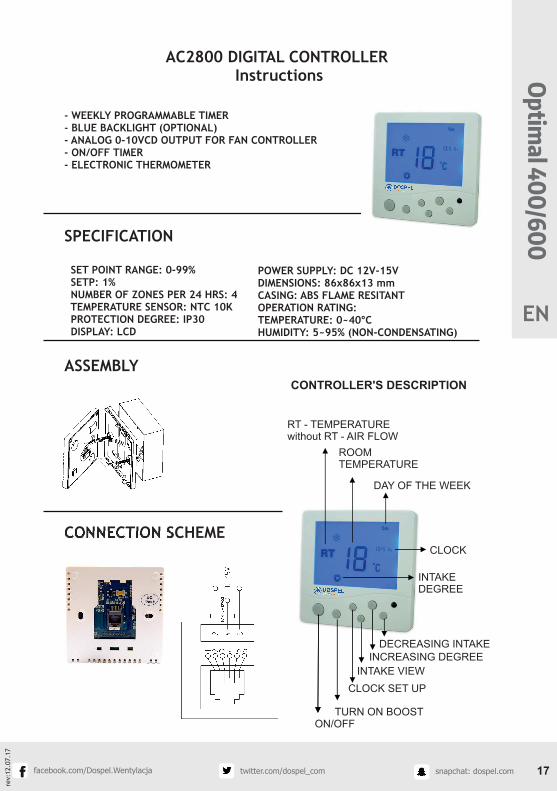
AC2800 DIGITAL CONTROLLERInstructions
- WEEKLY PROGRAMMABLE TIMER- BLUE BACKLIGHT (OPTIONAL)- ANALOG 0-10VCD OUTPUT FOR FAN CONTROLLER- ON/OFF TIMER- ELECTRONIC THERMOMETER
SPECIFICATION
SET POINT RANGE: 0-99% SETP: 1% NUMBER OF ZONES PER 24 HRS: 4 TEMPERATURE SENSOR: NTC 10K PROTECTION DEGREE: IP30 DISPLAY: LCD
ASSEMBLY
CONNECTION SCHEME
rev:
12.0
7.1
7
Op
tima
l 40
0/6
00
CONTROLLER'S DESCRIPTION
RT - TEMPERATUREwithout RT - AIR FLOW
ROOM TEMPERATURE
DAY OF THE WEEK
CLOCK
INTAKE DEGREE
DECREASING INTAKEINCREASING DEGREE
INTAKE VIEW
CLOCK SET UP
TURN ON BOOST ON/OFF
POWER SUPPLY: DC 12V-15VDIMENSIONS: 86x86x13 mmCASING: ABS FLAME RESITANTOPERATION RATING:TEMPERATURE: 0~40°CHUMIDITY: 5~95% (NON-CONDENSATING)
EN
rev:
12
.07
.17
Op
tim
al 4
00
/60
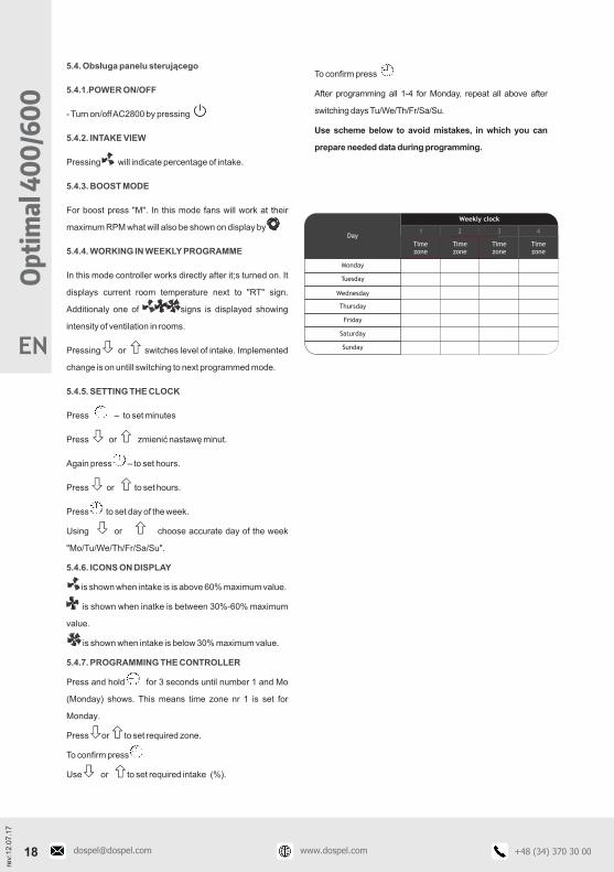
05.4. Obsługa panelu sterującego
5.4.1.POWER ON/OFF
5.4.2. INTAKE VIEW
5.4.3. BOOST MODE
5.4.4. WORKING IN WEEKLY PROGRAMME
5.4.5. SETTING THE CLOCK
5.4.6. ICONS ON DISPLAY
5.4.7. PROGRAMMING THE CONTROLLER
- Turn on/off AC2800 by pressing
Pressing will indicate percentage of intake.
For boost press "M". In this mode fans will work at their
maximum RPM what will also be shown on display by
In this mode controller works directly after it;s turned on. It
displays current room temperature next to "RT" sign.
Additionaly one of signs is displayed showing
intensity of ventilation in rooms.
Pressing or switches level of intake. Implemented
change is on untill switching to next programmed mode.
Press – to set minutes
Press or zmienić nastawę minut.
Again press – to set hours.
Press or to set hours.
Press to set day of the week.
Using or choose accurate day of the week
"Mo/Tu/We/Th/Fr/Sa/Su".
is shown when intake is is above 60% maximum value.
is shown when inatke is between 30%-60% maximum
value.
is shown when intake is below 30% maximum value.
Press and hold for 3 seconds until number 1 and Mo
(Monday) shows. This means time zone nr 1 is set for
Monday.
Press or to set required zone.
To confirm press Use or to set required intake (%).
55
55
5555
55
55
55
55
55
55
55
55
To confirm press
After programming all 1-4 for Monday, repeat all above after
switching days Tu/We/Th/Fr/Sa/Su.
Use scheme below to avoid mistakes, in which you can
prepare needed data during programming.
Weekly clock
Day
Time zone
1 2 3 4
Time zone
Time zone
Time zone
Monday
Tuesday
Wednesday
Thursday
Saturday
Friday
SundayEN

rev:
12
.07
.17
Op
tima
l 40
0/6
00
400
95
600
recu
pera
tive
AC2800 co
ntro
ller
Varia
ble
speed re
gula
tion
RVU
BVU
FE
A+
A+
B
OPTIM
AL 6
00
OPTIM
AL 6
00
OPTIM
AL 4
00
OPTIM
AL 4
00
-33
-33
-69
-69
-10
-10
DO
SPEL
DO
SPEL
Supplie
r
Device
indentifie
r
Specific e
nerg
y consu
mtio
n (SE
C)
- ave
rage clim
ate
Specific e
nerg
y consu
mtio
n (SE
C)
- cold
climate
Specific e
nerg
y consu
mtio
n (SE
C)
- warm
climate
SEC ra
nge
- ave
rage clim
ate
SEC ra
nge
- cold
climate
SEC ra
nge
- warm
climate
Device
type
Type o
f drive
Heat re
cove
ry system
Therm
al e
fficiency
of h
eat re
cove
ry
Maxim
um
flow
rate
Fan's d
rive p
ow
er
consu
ptio
n
Sound p
ow
er le
vel (L
)w
a [d
B(A
)] 5
2 5
3
[]
3m
/h
[]
W140
200
%
Unit
Inte
rnal le
akage ra
te
Filte
r change w
arn
ing sig
nal
Website
Annual e
lectricity co
nsu
mptio
n
2per 1
00 m
Contro
l facto
r (CTRL)
The a
nnual h
eatin
g sa
ved
(cold
climate
)
The a
nnual h
eatin
g sa
ved
(ave
rage clim
ate
)
Inte
rnal le
akage ra
te
The a
nnual h
eatin
g sa
ved
(warm
climate
)
Flo
w ra
te
Pre
ssure
diffe
rence
rate
Specific p
ow
er in
put (SP
I)
Pro
duct in
form
atio
n a
ccord
ing to
Com
missio
n R
egula
tion n
o 1
253/2014 a
nd C
om
missio
n R
egula
tion n
o 1
254/2014
3[m
/s]
0,0
80,1
2
OPTIM
AL 6
00
OTIM
AL 4
00
Unit
[Pa]
50
50
ww
w.d
osp
el.co
m
85
[kW
h p
rimary
energ
y/ye
ar]
[kW
h p
rimary
energ
y/ye
ar]
44
43
[kW
h p
rimary
energ
y/ye
ar]
20
20
[kW
h/ye
ar]
441
422
%N
ot m
ore
than 2
0,9
5
%N
ot m
ore
than 2
Visu
al filte
r ch
ange w
arn
ing sig
nal
0,3
50,3
3[W
/(
]3
m/h)
EN

DOSPEL Sp. z o.o.ul. Główna 188
42-280 Częstochowatel. +48 34 365 98 43fax +48 34 360 97 00
e-mail: [email protected]
Dospel reserves the right to introduce any changes regarding its products resulting from ongoing technical development. Dospel shall not be liable for printing errors.
![Untitled-2 [suntracbatteries.com]suntracbatteries.com/suntrac.pdf · capacity 12v 20ah 12v 40ah 12v 60ah 12v b40ah 12v b60ah 12v b80ah 12v biooah 12v 80ah 12v iooah 12v 130ah 12v](https://static.fdocuments.us/doc/165x107/603efb7aa12c32391f5484d1/untitled-2-capacity-12v-20ah-12v-40ah-12v-60ah-12v-b40ah-12v-b60ah-12v-b80ah.jpg)


