
DTIC · Return these stakes IAW the Technical Manual and continue to operate the MK-2551 provided...
45
AD-A277 285 RESEARCH AND DEVELOPMENT TECHNICAL REPORT CECOM-TR-94-8 Engineering Application Notes: Grounding Kit, MK-2551 A/U (Surface Wire Ground System) John M. Tobias DTIC CECOM Safety Office ELECTE MR 12 1994 February 1994 5S AF D DISTRIBUTION STATEMENT: Approved for Public release; distribution is unlimited. 94-08962 CECOM U-S, AR4MY CONMMUNCATIONS-ELECTRONICS COMMAND C'ECOM SAFETY OFFICE Al-rN: AMSEL-SF-SEP FORT MONMOUTH, NEW JERSEY 07703-W024 94 8 21 026 - D2ft
Transcript of DTIC · Return these stakes IAW the Technical Manual and continue to operate the MK-2551 provided...
AD-A277 285
RESEARCH AND DEVELOPMENT TECHNICAL REPORTCECOM-TR-94-8
Engineering Application Notes:Grounding Kit, MK-2551 A/U(Surface Wire Ground System)
John M. Tobias DTICCECOM Safety Office ELECTE
MR 12 1994
February 1994 5S AF DDISTRIBUTION STATEMENT:Approved for Public release;
distribution is unlimited.
94-08962
CECOMU-S, AR4MY CONMMUNCATIONS-ELECTRONICS COMMANDC'ECOM SAFETY OFFICE Al-rN: AMSEL-SF-SEPFORT MONMOUTH, NEW JERSEY 07703-W024 94 8 21 026
- D2ft
NOTICES
Disclaimers
The findings in this report are not to be construed as anofficial Department of the Army position, unless so desig-nated by other authorized documents.
The citation of trade names and names of manuuacturers inthis report is not to be construed as official Governmentendorsement or approval of commercial products or servicesreferenced herein.

REPORT DOCUMENTATION PAGE J A f MIA~~ikUW40610 otES "%~a~m ~tuwat" .6hINWAW I kuwe 'or. iigESSr inawwaq UEStmuEg eaing us
aid109W WI s MWWaif~ .lmisanmL Serwms. ftscU~watOsursfog aDC "M.UsJe
1.AGENCY USE ONLY (Leve bmnkJ 2. REPORT DATE 3. REPORT TYPE AND DATES COVERED
I February 1994 I Technical Report
7. TEPIME N ORAUS ATIO LAES ANDOW ADORESS(E
USGINARMY G APPICATIONNOTEC:TGROUNDICOMMAND (CCMK-51A
CECOM SAFETY OFFICE CECOM-TR-94-8ATTN: AMSEL-SF-SEPFort Mornmouth, NJ 07703-5024
9. SPONSORINGIMONITORING AGENCY NAME(S) AND ADDRESS(ES) 10.SPONSORING /MONITOUJNGAGENCY REPORT NUMBER
11. SUPPLEMENTARY NOTES
U&s DISIBUTliN AVAILAUUJTY STATEMENT [12b. DISTRIUTION CODE
Approved for public release; distribution is unlimited.I
13. ABSTRACT 6Waxhnum 200 w&s
This report discusses the description, specifications, theory of operation,employment principles, and test results of the MK-2551 Grounding Kit, also knownas the Surface Wire Ground System (SWGS). Design information is included forapplication of this system to specific designs. The report is intended to filla gap in the knowledge available to the design and development commnunity.Application and employment principles are developed from test results augmentedby validated theoretical performance models. Explanations of installation,removal, and maintenance operations are also presented.
1. SUWECT TERM 15. NUMBER OF PAGES
MK-2551; Grounding Kit; Surface Wire Ground System; ElectricalGrounding; NSN 5820-01-263-1760 1IL PUICE CODE
17. ECUITYSICIM LASrIC 7 . SCUF CLSSFATM 20. LMITATION OF A§STRACT
Unclassified Unclassified Unclassified ULWN -28SwStndatd Fotwn 296 MRV. 2-69)
ftW.0*8 yA M 01

Table of Contents
1.0 General Description ....................................... 11.1 Component Notes .................................... 2
1.1.1 Ground Wire Assembly ........................... 21.1.2 Stakes 21. 1.3 Short Ground Wire Assembly ....................... 2
1.2 Reliability and Maintainability Data .......................... 2
2.0 Theory of Operation ....................................... 42.1 Basic Grounding Theory ................................ 4
2.1.1 Step Potential ................................. 52.2 Theoretical Resistance of MK-2551 ........................... 7
3.0 Proper Operational Procedures and Principles of Employment .............. 93.1 Preventative Maintenance Checks and Services .................... 93.2 Installation Instructions ................................ 103.3 Removal Instructions .................................. 113.4 Employment Principles ................................ 12
4.0 MK-2551 Configurations .................................... 134.1 Multiple Vehicle Applications ............................ 13
4.1.1 Principles for Multiple Vehicle Configurations .............. 134.2 Generators ........................................ 144.3 Large Equipment .................................... 144.4 Employment Restrictions ............................... 15
4.4.1 Duration .................................... 154.4.2 Multiple Vehicles ................................ 154.4.3 Non-Shelterized Equipment .......................... 15
5.0 Test Data ............................................. 165.1 Electrical Testing .................................... 16
5.1.1 Resistance to Ground ............................. 165.1.1.1 Test - Human Engineering Laboratory Grounding
Analyses - U (HELGA-I), USAHEL, various locations,1987 . ................................. 16
5.1.1.2 Test - USAF 1839 Engineering Installation Group,Keesler AFB, 14-18 August 1989 ................. 18
5.1.1.3 Test - Redstone Arsenal Technical Test Center, AL,Fall 1991 ................................ 19
5.1.1.4 Test - Communications Electronics Command SafetyOffice Grounding Lab, Fort Monmouth (Evans Area) NJ,December 1993 ............................ 20
1ii
5.1.2 Lightning Suitability Testing .......................... 225.1.2.1 Test - Redstone Arsenal Technical Test Center, AL,
Fall 1991 ................................ 225.1.2.2 Test - Redstone Arsenal Technical Test Center, AL,
Fall 1991 ................................ 235.1.2.3 Test - Redstone Arsenal Technical Test Center, AL,
Summer 1993 ............................. 255.1.3 Human Factors Data .............................. 26
5.1.3.1 Test - U.S. Army Test and Experimentation Command,Fort Hood, Texas, Oct.- Nov. 1993 ................ 26
6.0 References ........................................... 276.1 Literature Cited ..................................... 276.2 Other Sources ...................................... 27
7.0 Author's Note ......................................... 28
Appendix A - MK-2551 Drawings ................................. 29
iv

List of Figures
Figure 1 Grounding volume shells about the earth electrode .................... 4Figure 2 Step potential from a cloud-to-ground lightning strike ................ 6Figure 3 Approximate step potential profile as a function of distance from the ground
rod. . .................................................. 6Figure 4 Proper MK-2551 deployment ................................ 12Figure 5 Two vehicle MK-2551 deployment.............................. 13Figure 6 MK-2551 realized on a generator trailer ........................... 14Figure 7 MK-2551 realized on large equipment ........................... 15Figure 8 Theoretical resistance of SGR and MK-2551 with normalized soil
resistivity (y-axis) versus the frozen soil depth in centimeters (x-axis) ........ 21Figure 9 Step potential profiles of the MK-2551 and the MX148/G, under 20,000
ampere peak current injection. (Average lightning strike levels.) ........... 23Figure 10 Theoretical values of the step potentials MK-2551and MX-148/G.
Conditions considered are identical to the Redstone Arsenal testing .......... 24Figure 11 Step potential (kV) vs distance for MK-2551 and short rod. Flat lines at
center represent a gap between probe locations ...................... 25
Acce:;ion For
NTIS ,:RA&I
L~i
By ................ . ............
Dist: ibutionr I
Avai!ability "- c-s
Avaif ai.A or
Dist j Special'
IA I
v

List of Tables
Table 1 MK-2551 Components .................................... ITable 2 PM CS Table .......................................... 9
A
Preface
This technical report is intended to answer many of the common questions regardingapplication of the MK-2551 grounding kit. We attempt to explain the operating theory andprinciples to an extent that a design engineer can understand the reasons behind the operatinginstructions in the MK-2551 technical manual. While it is impossible to list every possibleMK-2551 configuration, we list the important considerations as a guide in %veloping systemspecific applications. The information presented herein represents the best informationavailable to date, including recently completed testing and preliminary data from equipmentusers. We hope that it is useful in developing your applications.
vii
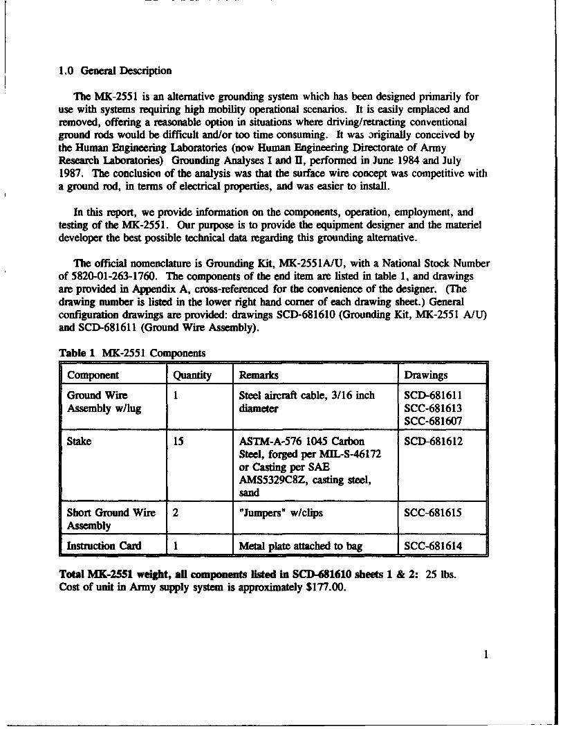
1.0 General Description
The MK-2551 is an alternative grounding system which has been designed primarily foruse with systems requiring high mobility operational scenarios. It is easily emplaced andremoved, offering a reasonable option in situations where driving/retracting conventionalground rods would be difficult and/or too time consuming. It was originally conceived bythe Human Engineering Laboratories (now Human Engineering Directorate of ArmyResearch Laboratories) Grounding Analyses I and UI, performed in June 1984 and July1987. The conclusion of the analysis was that the surface wire concept was competitive witha ground rod, in terms of electrical properties, and was easier to install.
In this report, we provide information on the components, operation, employment, andtesting of the MK-2551. Our purpose is to provide the equipment designer and the materieldeveloper the best possible technical data regarding this grounding alternative.
The official nomenclature is Grounding Kit, MK-2551A/U, with a National Stock Numberof 5820-01-263-1760. The components of the end item are listed in table 1, and drawingsare provided in Appendix A, cross-referenced for the convenience of the designer. (Thedrawing number is listed in the lower right hand corner of each drawing sheet.) Generalconfiguration drawings are provided: drawings SCD-681610 (Grounding Kit, MK-2551 A/U)and SCD-681611 (Ground Wire Assembly).
Table 1 MK-2551 Components
Component Quantity Remarks Drawings
Ground Wire 1 Steel aircraft cable, 3/16 inch SCD-681611Assembly w/lug diameter SCC-681613
SCC-681607
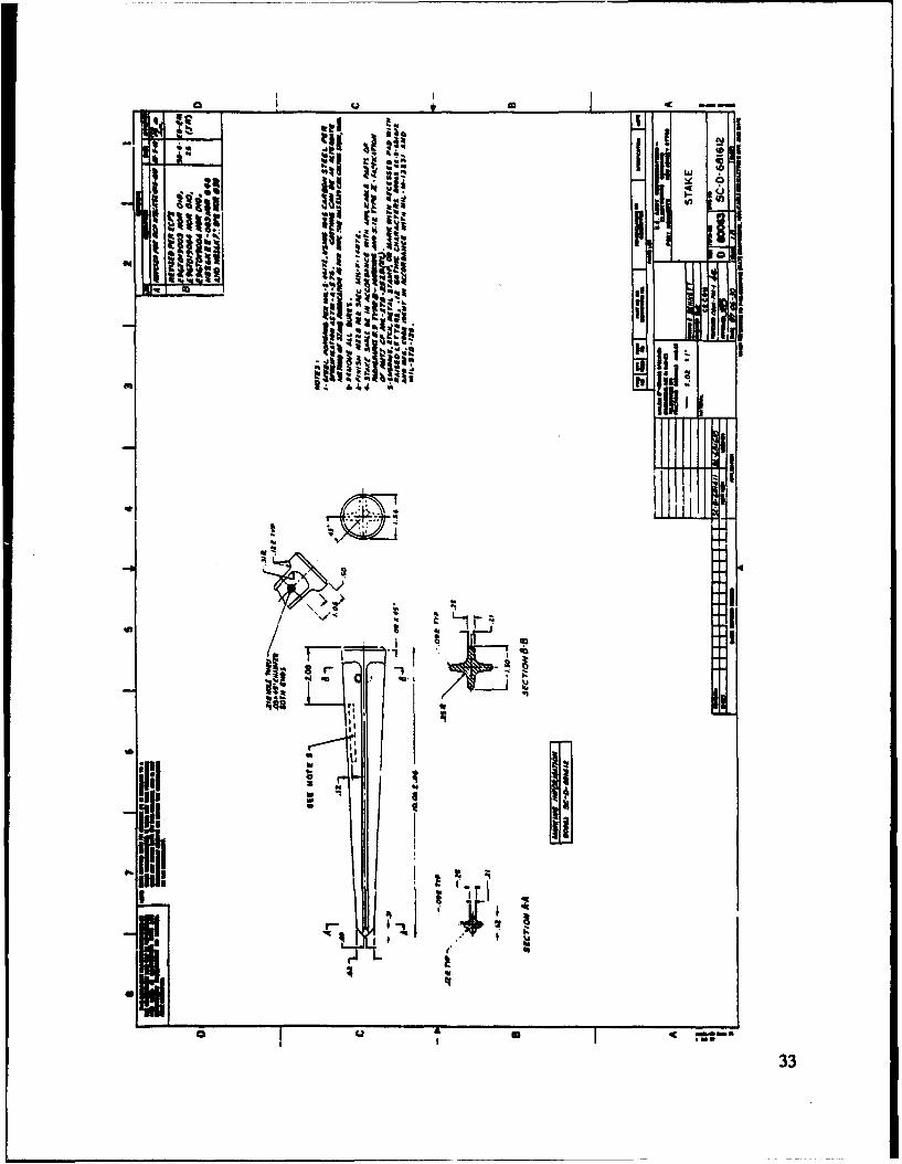
Stake 15 ASTM-A-576 1045 Carbon SCD-681612Steel, forged per MIL-S-46172or Casting per SAEAMS5329C8Z, casting steel,sand
Short Ground Wire 2 "Jumpers" w/clips SCC-681615Assembly
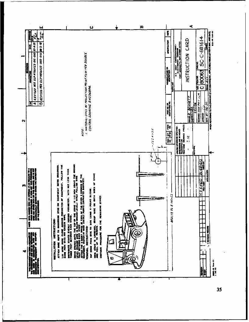
Instruction Card I Metal plate attached to bag SCC-681614
Total MK-2551 weight, all components listed in SCD-681610 sheets 1 & 2: 25 lbs.Cost of unit in Army supply system is approximately $177.00.

1.1 Component Notes
1.1.1 Ground Wire Assembly
Verify the proper cable size before accepting an MK-2551. Prior to testing andvalidation, the main cable diameter was ¼A-inch, since changed to 3/16-inch. Early units andsome units produced by various manufacturers have incorrect cables. The effect of thesmaller cable is to degrade the MK-2551's ability to withstand the maximum percentilelightning strike. Failure under lightning current will occur approximately 5 % to 10% ofoccurrences if the ¼A-inch cable is used. The lug is also constructed of steel and is madeespecially for the MK-2551 for the same purposes. Preliminary data suggest thatreplacement with a copper lug may be practical, and we are exploring this possibility. Untilthe suitability of a copper lug can be verified, it is important to use the existing lug specifiedin the drawings.
1.1.2 Stakes
The stakes are typically cast steel, this method of construction being cheaper than forging.Preliminary user data and consultation with material laboratories' suggests that up toapproximately 2% of castings are inherently flawed. This means that a small percentage ofMK-2551 stakes will break, most likely the first time they are impacted with the sledgehammer. Return these stakes IAW the Technical Manual and continue to operate the MK-2551 provided that 13 or more stakes remain operational on the system. Unauthorizedcopies of the MK-2551 use various materials for the stakes, making them prone to breakageor deformation.
1.1.3 Short Ground Wire Assembly (Jumper cables)
These remain 'A-inch diameter cable. Their employment is mandated by the results ofhigh current lightning tests. They provide an auxiliary path for very high current events,which divert current from the main wire, enhancing its survivability. When installed, thejumpers make the MK-2551 more survivable under high current lightning events than thestandard ground rod kit. A frequent complaint is that the clips do not stand up well to wearand tear in field use. We are in the process of identifyLig a replacement clip.
1.2 Reliability and Maintainability Data
Little reliability data is currently available. We expect more to become available asmore applications using MK-2551 are realized. Informal surveys of developmentalprograms suggest that the MK-2551 suffers damage about every thirty uses. The typical
' Meeting with G.T. Lamar, General Engineer, U.S. Army Missile Command Research
and Development Center, September 1993.
2

mode of damage identified is main wire breakage caused by accidental repeated strike by thehammer when installing the kit. We point out that individual parts for the MK-2551 can beordered, in accordance with the technical manual instructions. Defining reliability in a costper use aspect, the cost per use is approximately $177/30 uses = $5.90 per use, assumingthat the total MK-2551 needs replacement, which is most likely not true. Compare this to aground rod which will typically survive only one or two uses. Assuming an approximate$10.00 unit cost, then the cost per unit use is approximately $10/2 = $5.00 per use. Theconclusion is that the MK-2551 is competitive in terms of cost per unit use with the groundrod, especially since the entire kit does not need replacement if breakage occurs.
3

2.0 Theory of Operation
In this section, we explore the physical nature of theoperation of the MK-2551 and grounding systems ingeneral. In conclusion we present a resistance model , ..
for the MK-2551 that we have recently developed. We r,, ,encourage use of the resistance model to determine if , ii ,II i -the MK-2551 meets your needs. I ; ,, 11
2.1 Basic Groundinig Th'leory I': 1 -
Resistance to ground is based on the ability of theearth electrode, whether it is the MK-2551 or a ground'"> Yrod, to transfer the current to the bulk earth Fgr rudn ouesel busurrounding it. It does this through a series of Fgr rudn ouesel bucylindrical shells, as illustrated in figure 1. The the earth electrode.important electrical characteristic that all groundingequations are dependent on is the resistivity of the earth surrounding the electrode,designated here by the symbol p. As a simple example, we can derive an approximateexpression for the resistance to ground of a simple groundJ rod.
Equation 1 yields the Current Density within earth as a functionof x, the distance from the ground rod and 1, the depth of theground rod. Note that it is given by dividing the injection _ _
current by the surface area of the cylindrical shells about the earth X2=1x
electrode. It is in units of amperes per unit area, as the injectioncurrent is expressed here as 1. The current could be up to200,000 amperes in a maximal lightning event.
From Ohm's law, electric field strength E, in units of volts perunit length may be found by multiplying the current density i by E = (2)the soil resistivity, p. X 2=,
Find the potential (voltage) as a function of x by integrating the ,
field over x, the distance from the ground rt Vh=fEdx (3)
r
We can substitute the electric field term E in equation 3 and integrate, which yields equation5, an approximate expression for the potential drop as a function of distance from the groundrod.
4
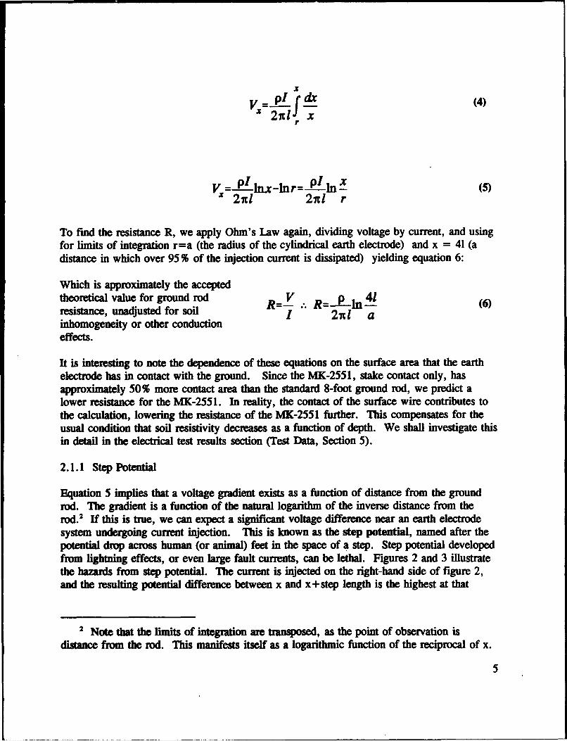
X(4)
V = P I dx (n4)l n
2nIl 2nl r
To find the resistance R, we apply Ohm's Law again, dividing voltage by current, and usingfor limits of integration r=a (the radius of the cylindrical earth electrode) and x = 41 (adistance in which over 95 % of the injection current is dissipated) yielding equation 6:
Which is approximately the acceptedtheoretical value for ground rod R=V.'. R=_p In 41 (6)resistance, unadjusted for soil 2nI ainhomogeneity or other conductioneffects.
It is interesting to note the dependence of these equations on the surface area that the earthelectrode has in contact with the ground. Since the MK-2551, stake contact only, hasapproximately 50% more contact area than the standard 8-foot ground rod, we predict alower resistance for the MK-2551. In reality, the contact of the surface wire contributes tothe calculation, lowering the resistance of the MK-2551 further. This compensates for theusual condition that soil resistivity decreases as a function of depth. We shall investigate thisin detail in the electrical test results section (Test Data, Section 5).
2.1.1 Step Potential
Equation 5 implies that a voltage gradient exists as a function of distance from the groundrod. The gradient is a function of the natural logarithm of the inverse distance from therod2 If this is true, we can expect a significant voltage difference near an earth electrode
system undergoing current injection. This is known as the step potential, named after thepotential drop across human (or animal) feet in the space of a step. Step potential developedfrom lightning effects, or even large fault currents, can be lethal. Figures 2 and 3 illustratethe hazards from step potential. The current is injected on the right-hand side of figure 2,and the resulting potential difference between x and x+step length is the highest at that
2 Note that the limits of integration are transposed, as the point of observation is
distance from the rod. This manifests itself as a logarithmic function of the reciprocal of x.
5

point. We can see in figure 2 that steppotential is dependent on step length,making it a greater hazard to the farmanimal pictured. 3
This effect can be a significant hazardin grounding systems, and we willdetail the step potential for the MK-2551 in the test data section. Our intenthere is to impart to the design engineera thorough understanding of this hazard,so that it may be considered in STE VLTAGE --.--
grounding system design. Our positionis that any location out of doors, ErTCE
especially near grounding systems, is Figure 2 Step potential from a cloud-to-groundhazardous, and ..' ld be avoidedduring electrical storm conditions. The lightning strike.best possible course of action is toremain inside a grounded enclosure.
1.106I
0 10 20 30 40 50X, METERS
Figure 3 Approximate step potential profile as a function of distance from the ground rod.
3 Animal fatalities from step potential caused by lightning and fault currents in dairy
plants is a significant cause of lost profit in the dairy and beef industries.
6

2.2 Theoretical Resistance of MK-2551
We have prepared a model to estimate the resistance of the MK-2551. No model waspreviously available for this system. It is validated in the test results by the close agreementof the theoretical and actual step potential of the system (See 5.1.2.2.). Without deriving theequations from theory, we can calculate the resistance of the MK-2551.' In this calculation,we use the following dimensions:
1 = stake length (25 cm) a = equivalent stake diameter (1.5 cm)a.= wire diameter (.24 cm) rw = wire loop radius (679 cm)1.= length of surface wire (2133 cm) n = number of stakes (15)
and we use the following equations in the calculation.
Resistance of n stakes to ground. R-= 2-Po[1n( 4)-1 +_!L ln(2r)] (7)2n arw
Resistance of surface wire in contact to Rw- = 2 n(-r) (8)ground. 2n rw9)
Mutual resistance term. R -L W) (9)
Combined res, found by RwRrR 2 rsubstituting the above terms. RM2s51 - RwRr+Rvf4 (10)
MRw+ 2Rwr
4 Sunde, E.G., Earth Conduction Effects in Transmission Systens, Dover Publications,
New York, 1968.
7

If we use normalized resistivity; p = I ohm-cm, the calculations yield:
Rm.551 = 0.001 lpRMX14S = 0.0045p
Meaning that in theory, the ratio of the MK-2551 resistance to the MX-148 ground resistanceunder similar conditions, is approxmately 'A, which is an adequate rule of thumb.
8

3.0 Proper Operational Procedures and Principles of Employment
In this section we detail the intended, approved procedures for MK-2551 deployment andoperation. We shall also attempt to answer some of the typical questions and concernsdesigners ask about the MK-2551, and explain the rationale behind some of the procedures.
3.1 Preventative Maintenance Checks and Services
Preventative Maintenance Checks and Services (PMCS) are key in the performance ofany system, as these checks serve to identify and correct materiel deficiencies in the itembefore it is used. Every time the grounding kit is set up, the PMCS should be performed.These are found as a table in the equipment technical manual. We will duplicate the PMCStable in the SWGS TM5 here and explain each item. In the PMCS table (table 2), anunsuitable condition renders the item as "not fully mission capable."
Table 2 PMCS Table
Item Interval Location/ Procedure Not fully ExplanationItem to check mission capableor service if:
1 Before/ Cable Asy Inspect for Cable is Frayed or broken cable willAfter obvious breaks broken, frayed increase resistance, causing anOperation or kinks, or twisted, unsuitable ground. Severe
Replace or lightning will break the cablestraighten. if it is kinked or twisted.
2 Before/ Clamp Inspect for Clamp is Eventual clamp failure willAfter corrosion. corroded. cause stakes to separate fromOperation Clean the wire. MK-2551 may
continue operations if asubstitute clamp is notavailable.
3 Before/ Clamp Inspect for Clamp is loose. Stakes will be free to separateAfter proper from the wireOperation connection.
Tighten(continued)
5 Technical Manual 11-5820-1118-12&P, Technical Manual Operator's and UnitMaintenance Manual, etc. for Grounding Kit, MK-2551 A/U, Department of the Army,Communications-Electronics Command, date TBD.
9
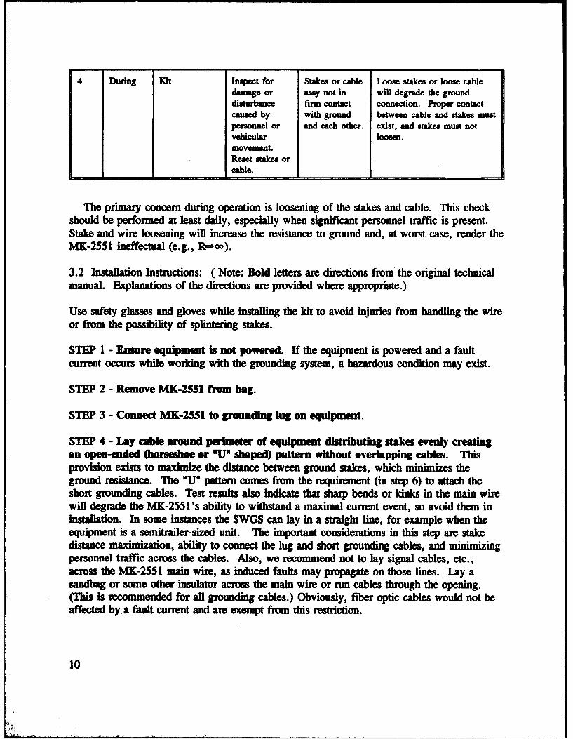
4 During Kit Inspect for Stakes or cable Loose stakes or loose cabledamage or any not in will degrade the grounddisturbance firm contact connection. Proper contactcaused by with ground between cable and stakes mustpersonnel or and each other. exist, and stakes must notvehicular loosen.movement.Reset stakes orcable.
The primary concern during operation is loosening of the stakes and cable. This checkshould be performed at least daily, especially when significant personnel traffic is present.Stake and wire loosening will increase the resistance to ground and, at worst case, render theMK-2551 ineffectual (e.g., R=*oo).
3.2 Installation Instructions: ( Note: Bold letters are directions from the original technicalmanual. Explanations of the directions are provided where appropriate.)
Use safety glasses and gloves while installing the kit to avoid injuries from handling the wireor from the possibility of splintering stakes.
STEP 1 - Ensure equipment is not powered. If the equipment is powered and a faultcurrent occurs while working with the grounding system, a hazardous condition may exist.
STEP 2 - Remove MK-2551 from bag.
STEP 3 - Connect MK-2551 to grounding lug on equipment.
STEP 4 - Lay cable around perimeter of equipment distributing stakes evenly creatingan open-ended (horseshoe or " shaped) pattern without overlapping cables. Thisprovision exists to maximize the distance between ground stakes, which minimizes theground resistance. The "U" pattern comes from the requirement (in step 6) to attach theshort grounding cables. Test results also indicate that sharp bends or kinks in the main wirewill degrade the MK-2551's ability to withstand a maximal current event, so avoid them ininstallation. In some instances the SWGS can lay in a straight line, for example when theequipment is a semitrailer-sized unit. The important considerations in this step are stakedistance maximization, ability to connect the lug and short grounding cables, and minimizingpersonnel traffic across the cables. Also, we recommend not to lay signal cables, etc.,across the MK-2551 main wire, as induced faults may propagate on those lines. Lay asandbag or some other insulator across the main wire or run cables through the opening.(This is recommended for all grounding cables.) Obviously, fiber optic cables would not beaffected by a fault current and are exempt from this restriction.
10

STEP 5 - Begin with the stake closest to the grounding stud. Pull cable taut. Twiststake 30 to 45 degrees. Drive stake until top is flush with ground. Continue until aDstakes are driven into ground. Cable tautness and twisting the stake are measures toguarantee a good electrical stake to main wire contact. Note that the cable between theshelter and the first stake should not be taut. Installing the stake flush with or slightlyimpacted into the ground will hold the main wire in place. This yields a surprisingly goodcontact (Rs-r T w Om 0.1-0.3 0), but requires periodic checking, as discussed in theprevious section.
STEP 6 - Attach jumper cables. Connect one from front bumper of vehicle to center ofcable; connect second from rear bumper to end of grounding cable. The "jumper" orshort grounding cables are attached approximately equidistant on the main wire connected toequipment frame bonded to ground. The purpose of these cables is to meet high-currentsurvivability guidelines' (e.g., a 200,000 ampere peak current event as found in naturallightning). With these connections, the MK-2551 can withstand higher current events thanthe standard MX148/G ground rod kit commonly found in military applications. Moreinformation on this aspect of the MK-2551 will be discussed in test results, Section 5. It isnot necessary to scrape paint away to improve the clip contact, as this is a secondary currentpath. (Scraping the paint will, however, improve the contact. Under high currentconditions, the paint will vaporize as it is not resistive enough to prevent flashover. Clipcontacts used in testing were not scraped.)
3.3 Removal Instructions:
STEP 1 - Disconnect equipment power and discharge supply capacitors. This exists forthe same reason as step 1 of the installation instructions.
STEP 2 - Remove jumper cables.
STEP 3 - Remove terminal lug from grounding stud.
STEP 4 - Tap each peg from side to side using the hanrzier provided with the kit. Inactuality, you may find that lifting up on the main wire on either side of the stakes willusually be sufficient to remove the stake.
STEP 5 - Once a peg is loosened, grasp the cable on both sides of it and pulf up toremove. Use gloves to do this!
STEP 6 - Continue this procedure until all stakes are removed.
6 Military Handbook: Grouding Bonding and Shielding for Electronic Equipment and
Fadlides; MJL-HDBK-419, Department of Defense, Washington D.C., 1982.
11

STEP 7 - Coil cables. Place grounding kit and hammer in tool bag.
3.4 Employment Principles
The basic principles of MK-2551 employment were stated earlier, but we repeat them herefor clarity:
* Stake separation distance maximization (i.e., use all of the cable).
0 Ability to connect the lug and short grounding cables, at approximately equidistantpoints on the main cable, while avoiding sharp bends.
* Minimize personnel traffic across the cables (e.g. allow an access point to theequipment for service and other cables).
By following the basic employment principles, a safe deployment of MK-2551 is possible, asiliustrated in figure 4.
CANVAS CARRYING THRCEPOWR ETRYCASE POUND
PANEL GROUND kHAMMERICONNECTOR
CABLECABEL
lTC ABLE 10 FT STEEL CABLES (2) WITHAND PEGS 75 AMP COPPER CUPS
Figure 4 Proper MK-2551 deployment.
12

4.0 MK-2551 Configurations
The single vehicle application of the MK-2551 was depicted in figure 4. Instructionsgiven in section 3 were for this use. More specific instructions may have to be developedfor different configurations, particularly those requiring several MK-255 l's.
4.1 Multiple Vehicle Applications
The configurations illustrated in figure 5 are possible in cases of multiple vehicleassemblages, or for other unusual applications. The MK-2551 does not lend itself well forthese applications, as it was designed for a high mobility, single vehicle application.Assemblages of several vehicles do not lend themselves to quick setup either and users mayfind it easier to drive a single ground rod and make multiple connections to it. We havefound from human factors data in typical operating scenarios that if several MK-2551 's aredeployed, a time savings will result from using a single ground rod.
4.1.1 Principles for Multiple Vehicle Configurations
We are frequently asked how to deploy the MK-2551 in multiple vehicle configurations.In this section, we illustrate some appropriate installations of the MK-2551. In these casesthe deployment principles (3 connections, equidistant; maximal stake separation; minimizepersonnel traffic) remain unchanged. Already we note that the MK-2551 connections on thevehicles on the right side of the drawing are not quite equidistant in terms of their positionon the main wire. One MK-2551 should be used with each equipment item because of therequired triple connection. If a single MK-2551 were used with two, three or more
JUMPERS
MAR WHIE
VEHICLE VEHICLE
Figure 5 Two vehicle MK-2551 deployment.
13

shelters/vehicles, the connection to each would violate the triple equidistant connectionprinciple, rendering the MK-2551 less than optimally effective for maximal current events.In figure 5, we illustrate an installation of two vehicles using MK-2551. One can easily seethat addition of more vehicles in close proximity will complicate this deployment schemegreatly. Also, vehicles closer that 8 feet must be bonded together electrically (with #6 AWGcable, or a larger gauge), which is best accomplished at the equipment grounding studs(usually on the power entrance panel).
It is also worth noting that the sections of wire that lay in close proximity to each other havetheir individual ground effectiveness reduced if the wires (and therefore, the stakes) are notat least 40 inches from each other. Note also that if the systems are bonded at the groundstud the grounding systems are electrically continuous.
4.2 Generators
Another probable application with the MK-2551 is on mobile power generators. A typicalinstallation is illustrated in figure 6.
Figure 6 MK-2551 realized on a generator trailer.
4.3 Large Equipment
As stated, the MK-2551 may be installed in essentially a straight line if the employmentprinciples are maintained. Figure 7 illustrates an example.
14

MAIN WIRE JUMPERS
EQUIPMENT
Figure 7 MK-2551 realized on large equipment.
4.4 Employment Restrictions
4.4.1 Duration
Use of the MK-2551 is not authorized for permanent or semi-permanent installations.Every day the MK-2551 is deployed, check the main wire and stakes for looseness. If thewire or stakes are loose, they must be reinstalled to improve the performance. Deploymentof the MK-2551 in applications that have high vehicle or personnel traffic in the vicinity mayresult in the necessity of more frequent checks. When formulating operating instructions forthe application, consider this aspect of operation.
4.4.2 Multiple Vehicles
Multiple vehicle use is discouraged, because of the complex setup involved with closegroupings of several vehicles. If necessary, designers may realize multiple vehicle MK-2551applications using the guidelines of section 4.1. Consider that a primary goal of the MK-2551 is to save time and effort in grounding. In nearly all cases, grounding of multiplevehicles with MK-2551, while maintaining the deployment principles, results in no time oreffort savings and also results in instructions that the user cannot understand. Usually, in ourexperience, consistent instructions cannot be developed, as it frequently depends on thenumber of vehicles. Since this is variable, or even initially unknown in some applications, itserves to increase confusion. Our advice in cases of multiple vehicle configurations is touse a standard ground rod, with multiple tie-in.
4.4.3 Non-Sbelterized Equipment
Other equipment, such as antenna masts may use the MK-2551, provided the employmentprinciples are followed. A notable exception to this is a stand alone tent configuration, orsimilar application. We do not recommend using the MK-2551 for this application primarilybecause of the danger of excessive step potentials should a lightning strike occur.
15

5.0 Test Data
During the development of the MK-255 1, various technical testing and user evaluation wasperformed. In this section we provide a summary of each test series and their results. Weare frequently asked for test data for the MK-2551, ranging from electrical properties tohuman factor installation/removal data. Our hope is that the test summary data providedhere is useful to designers. Tests conducted on initial configurations of Surface WireGrounding Systems (SWGS) are not included in this section as the physical componentdiffers from that realized in the MK-2551 (with the exception of the original HELGA - IItest, as it remains the best indicator of the resistance to ground properties of the SWGS invarious soil types). Some initial testing, notably that performed by the Belvoir Research andDevelopment center in 1986, raised suitability questions concerning the step potentials nearMK-2551, and survivability questions under lightning conditions. More detailed and recenttesting has since proved out the MK-2551, with multiple independent agencies endorsing theMK-2551.
5.1 Electrical Testing
5.1.1 Resistance to Ground
5.1.1.1 Test - Human Engineering Laboratory Grounding Analyses - 1 (HELGA-Il),USAHEL, various locations, 1987.
Test Objective: Comparison of SWGS to ground rod in differing soil conditions.
Test Conditions: Various (See table)
Test Equipment: MX148/G (6 foot) ground rodBiddle Megger null-balance earth tester.SWGS w/26 each 6-inch ground stakes, 100 foot main wire.
Results:
Soil Type Location R (0) R (0)SWGS MX148/G
Loam, moist surface T=60° Aberdeen Proving Ground, 37 46F MD (Old Airport)
Loam, snow covered Aberdeen Proving Ground, 61 248T=34° F MD (Main post area)
Frozen to depth of 4 inches Aberdeen Proving Ground, 70 100T=17°F MD (Phillips Army
Airfield) I(continued)
16
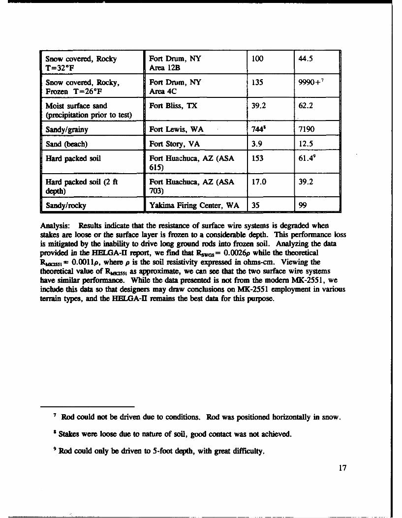
Snow covered, Rocky Fort Drum, NY 100 44.5T=32°F Area 12B
Snow covered, Rocky, Fort Drum, NY 135 9990+7
Frozen T=26*F Area 4C
Moist surface sand Fort Bliss, TX 39.2 62.2(precipitation prior to test)
Sandy/grainy Fort Lewis, WA 7443 7190
Sand (beach) Fort Story, VA 3.9 12.5
Hard packed soil Fort Huachuca, AZ (ASA 153 61.49615)
Hard packed soil (2 ft Fort Huachuca, AZ (ASA 17.0 39.2depth) 703)
Sandy/rocky Yakima Firing Center, WA 35 99
Analysis: Results indicate that the resistance of surface wire systems is degraded whenstakes are loose or the surface layer is frozen to a considerable depth. This performance lossis mitigated by the inability to drive long ground rods into frozen soil. Analyzing the dataprovided in the HELGA-H report, we find that RPswosf= 0.0026p while the theoreticalRum,= 0.00 lip, where p is the soil resistivity expressed in ohms-cm. Viewing thetheoretical value of Rmwj, as approximate, we can see that the two surface wire systemshave similar performance. While the data presented is not from the modern MK-255 1, weinclude this data so that designers may draw conclusions on MK-2551 employment in variousterrain types, and the HELGA-Il remains the best data for this purpose.
' Rod could not be driven due to conditions. Rod was positioned horizontally in snow.
s Stakes were loose due to nature of soil, good contact was not achieved.
9 Rod could only be driven to 5-foot depth, with great difficulty.
17
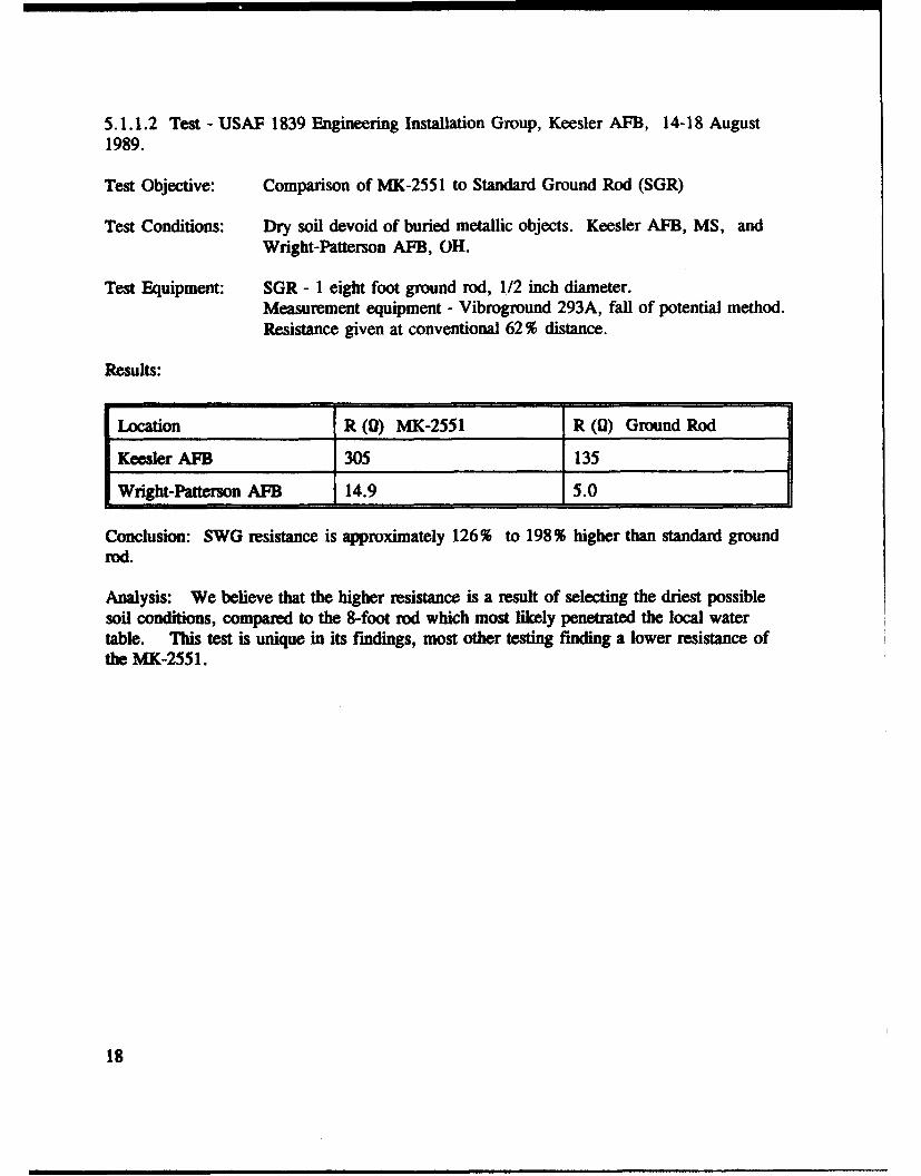
5.1.1.2 Test - USAF 1839 Engineering Installation Group, Keesler AFB, 14-18 August1989.
Test Objective: Comparison of MK-2551 to Standard Ground Rod (SGR)
Test Conditions: Dry soil devoid of buried metallic objects. Keesler AFB, MS, andWright-Patterson APB, OH.
Test Equipment: SGR - 1 eight foot ground rod, 1/2 inch diameter.Measurement equipment - Vibroground 293A, fall of potential method.Resistance given at conventional 62% distance.
Results:
Location R (0) MK-2551 R (0) Ground Rod
Keesler AFB 305 135
Wright-Patterson AFB 14.9 5.0
Conclusion: SWG resistance is approximately 126% to 198% higher than standard groundrod.
Analysis: We believe that the higher resistance is a result of selecting the driest possiblesoil conditions, compared to the 8-foot rod which most likely penetrated the local watertable. This test is unique in its findings, most other testing finding a lower resistance ofthe MK-2551.
18

5.1.1.3 Test - Redstone Arsenal Technical Test Center, AL, Fall 1991.
Test Objective: This test of resistance was a precursor to other testing.
Test Conditions: Dry soil with high clay and moisture content, p=27,500 ohms-cm.
Test Equipment: MK-2551MX148/GBiddle model #250241 earth tester.
Results:
R (0) MK-2551 R (0) Ground Rod
39.5 160
Analysis: This test is a good indicator for typical grounding situations.
19

5.1.1.4 Test - Communications Electronics Command Safety Office Grounding Lab, Fort
Monmouth (Evans Area) NJ, December 1993.
Test Objective: This test of resistance was a precursor to other testing.
Test Conditions: Various soil conditions as listed.
Test Equipment: MK-2551Biddle model #250302 earth tester.
Results:
R (0) MK- p of soil (ohms-cm) Conditions2551
120.7 2.1XI(0 T=40°F, surface moisture
132.7 1.8X10⁵ T=35°F, precipitation onprevious day
190.2 2.3X10 5 T=20°F, soil frozen to 3-inch depth
1416 1.3XI( (calculated - T=10°F, soil covered withbeyond measurement range) ice, frozen to 14-inch depth
197.6 2.4X10⁵ T=250 F, soil frozen to 3-4inch depth
Analysis: Performance is degraded by surface soil freezing, but may remain competitivewith a standard ground rod. Theoretical analysis (really a first order approximation) basedon both systems linear relationship with soil resistivity estimates that MK-2551 remainssuperior over a standard ground rod.',"' The results of this analysis are plotted in figure 8.Resistance of both systems should increase as frozen soil depth increases. Maximumresistance occurs when the soil is frozen to the depth of the grounding system. In figure 8we can see that the MK-2551 resistance increases to a maximum at a frozen soil depth equalto the stake depth and remains nearly constant. (According to MIL-HDBK-419, the soil
10 This conclusion is supported by early testing of a SWGS at the U.S. Army Cold
Regions Test Center, Fort Greely, Alaska. In this test, the SWGS was comparable toemplaced grounding systems using several ground rods.
" Development Test I of Surface Wire Ground System, Project # 6-ES-955-SWG-001,U.S. Army Test and Evaluation Command, U.S. Army Cold Regions Test Center, 1987.
20
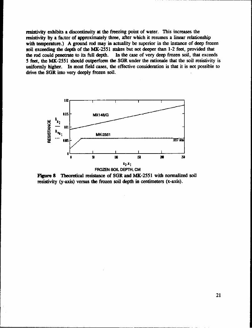
resistivity exhibits a discontinuity at the freezing point of water. This increases theresistivity by a factor of approximately three, after which it resumes a linear relationshipwith temperature.) A ground rod may in actuality be superior in the instance of deep frozensoil exceeding the depth of the MK-2551 stakes but not deeper than 1-2 feet, provided thatthe rod could penetrate to its full depth. In the case of very deep frozen soil, that exceeds5 feet, the MK-2551 should outperform the SGR under the rationale that the soil resistivity isuniformly higher. In most field cases, the effective consideration is that it is not possible todrive the SGR into very deeply frozen soil.
INf
0.05 - MX14WG
-- lAX MK-2551
Is IN Is IN2
FROZEN SOIL DEPTH, CM
Figure 8 Theoretical resistance of SGR and MX-2551 with normalized soilresistivity (y-axis) versus the frozen soil depth in centimeters (x-axis).
21

5.1.2 Lightning Suitability Testing
The MK-2551 does not comply with the provisions in the National Electrical Code, MI.L-HDBK419, or other standards for lightning protection. We wish to point out that thesestandards were written for fixed structures and not mobile systems. Despite thenoncompliance, the MK-2551 meets or exceeds the performance standards quoted in thecodes, proven by these test results.
5.1.2.1 Test - Redstone Arsenal Technical Test Center, AL, Fall 1991.
Test Objective: Determine lightning survivability of MK-2551 under realistic conditionswith direct injection of maximal lightning current.
Test Conditions: Dry soil with high clay and moisture content, p= 2 7 ,500 ohms-cm,MK-2551 deployed on HtMMWV, 200,000 amp peak injection, approx.50 microsecond duration.
Test Equipment: MK-2551MX148/GBiddle model # 250241 earth tester.High current lightning test facility.
Results: MK-2551 deployed without jumpers fractured. MK-2551 with jumpersdeployed survived several exposures to maximal lightning current. MX-148/Gdeployed with standard #6 AWG braid did not survive maximal current. The#6 braid fractured in several places after one exposure.
22

5.1.2.2 Test - Redstone Arsenal Technical Test Center, AL, Fall 1991.
Test Objective: Determine step potential profiles of MK-2551 and MXI48/G underrealistic conditions with direct injection of maximal lightning current..
Test Conditions: Dry soil with high clay and moisture content, 0 =27,500 ohms-cm,MK-2551 & MX-148/G deployed on HEMMWV, 200,000 amp peakinjection of approximately 50 microsecond duration.
Test Equipment: MK-2551MX148/GBiddle model #250241 earth tester.High current lightning test facility.
Results: The results are plotted in figure 9. While the MK-2551 has a higher steppotential initially, it falls off rapidly, achieving parity with the ground rod atapproximately 4 meters. The resultant area of step potential is larger than thatof the ground rod, as MK-2551 covers more area than the ground rod, whichis a "point source." The voltage measurements are taken from the ground rodand from the outside of the main wire of the MK-2551. Areas within theloop of the MK-2551 are irregular, but potentially very high. Since therelationship with the injection current is linear, hazards resulting from faultcurrents are correspondingly lower. For example, if a 20 amp fault cLrrentwere injected into the MK-2551, with the above conditions, the step potentialwould be one thousandth of the values on the y-axis in figure 9. These tend to
12.105 ,
0
0 1 .104
>o
0 100 200 300 400 500 600 700
DISTANCE, CM
Figure 9 Step potential profiles of the MK-2551 and the MX148/G, under20,000 ampere peak current injection. (Average lightning strike levels.)
23
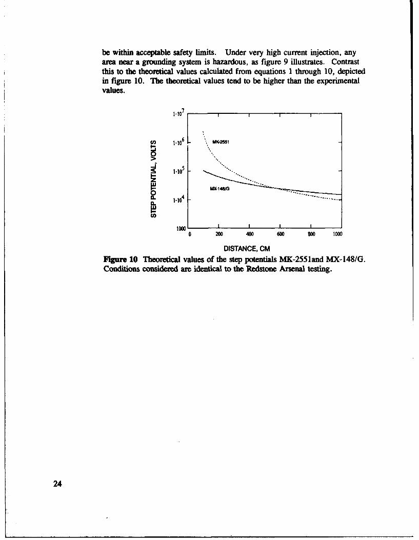
be within acceptable safety limits. Under very high current injection, anyarea near a grounding system is hazardous, as figure 9 illustrates. Contrastthis to the theoretical values calculated from equations 1 through 10, depictedin figure 10. The theoretical values tend to be higher than the experimentalvalues.
C03 1.10 6 . V, 255- 11"10 I. I
~ 410
5
0
1oo I I I
0 200 400 600 800 1000
DISTANCE, CM
Figure 10 Theoretical values of the step potentials MK-2551and MX-148/G.Conditions considered are identical to the Redstone Arsenal testing.
24
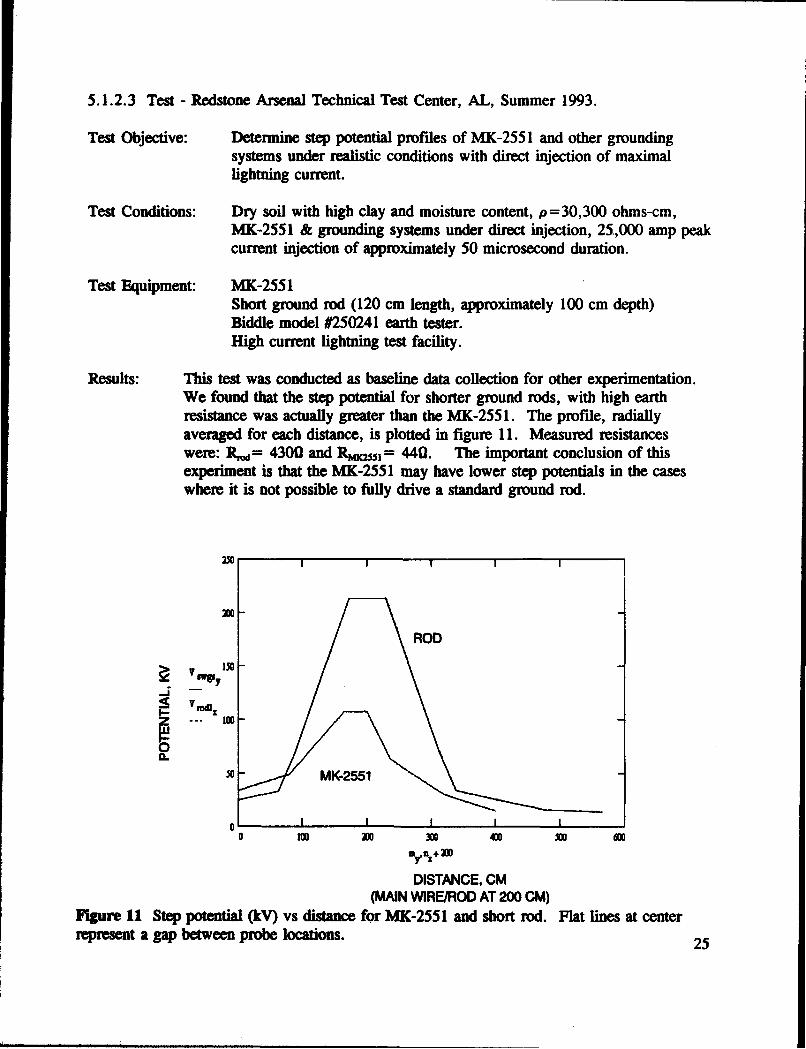
5.1.2.3 Test - Redstone Arsenal Technical Test Center, AL, Summer 1993.
Test Objective: Determine step potential profiles of MK-2551 and other groundingsystems under realistic conditions with direct injection of maximallightning current.
Test Conditions: Dry soil with high clay and moisture content, p=30,300 ohms-cm,MK-2551 & grounding systems under direct injection, 25.,000 amp peakcurrent injection of approximately 50 microsecond duration.
Test Equipment: MK-2551Short ground rod (120 cm length, approximately 100 cm depth)Biddle model #250241 earth tester.High current lightning test facility.
Results: This test was conducted as baseline data collection for other experimentation.We found that the step potential for shorter ground rods, with high earthresistance was actually greater than the MK-255 1. The profile, radiallyaveraged for each distance, is plotted in figure 11. Measured resistanceswere: R -= 4300 and RmK.l = 440. The important conclusion of thisexperiment is that the MK-2551 may have lower step potentials in the caseswhere it is not possible to fully drive a standard ground rod.
X0
15-
0
o I IO 100 300 300 4W X0 600
my n'+ me
DISTANCE, CM(MAIN WIRE/ROD AT 200 CM)
Figure 11 Step potential ^kV) vs distance for MK-2551 and short rod. Flat lines at centerrepresent a gap between probe locations. 25

5.1.3 Human Factors Data
In compiling this section, we found little formal data available. Older data, such as thatfound in the HELGA-Il reports, are not considered. We have only one formally documentedexperiment, but several developers report values ranging from 2 to 8.5 man-minutes,depending on soil hardness and the operator's level of training.
5.1.3.1 Test - U.S. Army Test and Experimentation Command, Fort Hood, Texas, Oct.-Nov. 1993.
Test Objective: Examine system set-up/tear-down times. MK-2551 was evaluated as anancillary task.
Test Conditions: Hard, rocky soil with high clay content, 8 event sample. Trainedpersonnel, one man deployment. Start and end conditions were MK-2551 stowed properly in its bag.
Test Equipment: MK-2551
Results: Mean time to set up: 8.63 minutes.Mean time to tear down: 11.63 minutes.
26

6.0 References
6.1 Literature Cited
Development Test I of Surface Wire Ground System, Project # 6-ES-955-SWG-001, U.S.Army Test and Evaluation Command, U.S. Army Cold Regions Test Center, 1987.
Military Handbook: Grounding Bonding and Shielding for Electronic Equipment andFacilities; MIL-HDBK-419, Department of Defense, Washington D.C., 1982.
Sunde, E.G., Earth Conduction Effects in Transmission Systems, Dover Publications, NewYork, 1968.
Technical Manual 11-5820-1118-12&P, Technical Manual Operator's and Unit MaintenanceManual, etc. for Grounding Kit, MK-2551 A/U, Department of the Army, CommunicationsElectronics Command, date TBD.
6.2 Other Sources
Hoskins, D.B., Lightning Ground Conductor Survivability Test Report, ElectromagneticEnvironmental Effects Branch, Redstone Technical Test Center, 1993.
Ramo, S., Melds and Waves in Communications Electronics Systems, Wiley, New York,1989.
Roy, T.E. and Henderson, R.P., Test Report for Surface Wire Ground Lightning Tests,Electromagnetic Environmental Effects Branch, Redstone Technical Test Center, 1992.
27

7.0 Author's Note
This Application Note was written with the intent of providing design engineers with thelatest and best possible information, theoretical and experimental, concerning the MK-2551.I've included the grounding theory to illustrate how the MK-2551 and other groundingsystems operate, and I hope that this provides the reader with some insight on the applicationof the MK-2551. Detailed operating instructions are included to provide not only the correctprocedure, but the reason for that procedure and some guidelines for unusual situations.Lastly, the condensed test data are included to demonstrate the comprehensive validation ofthe MK-2551.
I invite any user of the MK-2551 to add to these data. If you are using the MK-2551 andhave documented test results, please inform us here at the U.S. Army Communications-Electronics Command Safety Office. As you can see, we need more reliability and humanfactors data for this system. Similarly, I welcome any comments or questions that you mayhave. Please direct your data, comment, or inquiry to one of the following addresses:
U.S. Army Communications-Electronics CommandSafety Office, Systems Engineering DivisionATWN: AMSEL-SF-SEPFort Monmouth, New Jersey 07703-5024
Phone: (908) 532-0084 DSN: 992-0084
email: [email protected]. mil
28

Appendix A - MK-2551 Drawings
Nomenclatum Drawing Number
Grounding Kit, Surface Wire, MK-2551 SC-D-681610 (2 pages) 30,31Ground Wire Assembly SC-D-681611 32Stake SC-D-681612 33Wire Assembly SC-C-681613 34Instruction Card SC-C-681614 35Short Ground Wire Assembly SC-C-681615 36Terminal Lug SC-C-681607 37
29
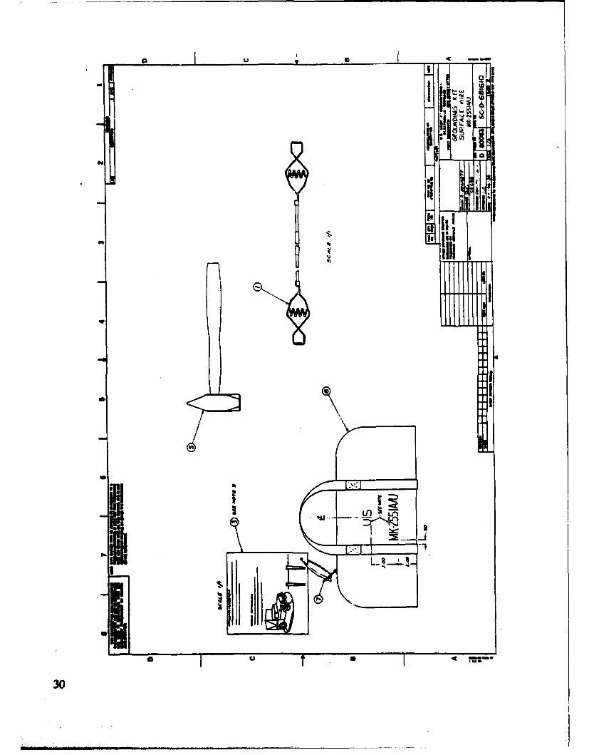
0 I ' 2f;7
on It --0
U, 'jj
I
li4-a • I m m,,
I~
II• i ii I ~ i l I i l l I I m m I l l..I

) 31

a U S
-� Ia,� :1* II5� 3
* AI� �a�I� "
'2eQ1 Ik#4
f
�
11111 Ii�*:3�
illi
:1
I- I
I
*
fRI *
p-ia II.1
32 u
- - I oft
'U ii.41 * I~I I-4 4 0T
bc 9~i 813* som
-
Cdlet
.. ~~L u.*
or
of i ~
lU
L ' FeI
,~ iiii33

Q a ii
Eli-iII:
I ts p"
34
'441 11
* -- I, UI
Itl
T: .
cm z
N•v,,, c.IjL
'd..
rI
allI d! i 9.ii :
III I
35

III-.'a- Li
Qvi IT-
I I- I "
C4 .h
'~ 1M
OfU.3L U
OUR)
:136 -I

lid-
IIIi !iI
~ U,
fill-7I
133"/


