DTIC QUALITY INSPECTED · Peter Shapiro and Sabina Shapiro 5 ... performance goals match Army...
142
High Frequency Alternator, Power Frequency Conversion (HFA-PFC) Technology for Lightweight Tactical Power Generation. Final Report CDRL sequence # 0001 AF 15 September 1995 Sponsored by Department of the Army (DoD) Defense Small Business Innovation Program Issued by U.S. A. CECOM Contract # DAAB-12-95-C-0016 Name of Contractor: JSP Industries, Inc. Business Address: P.O. Box 12127 8811 Hadley Overland Park, KS 66282-2127 Effective Date of Contract: 14 March 1995 Contract Expiration Date: 15 September 1995 Reporting Period: From 14 March 1995 to 15 September 1995 Principal Investigator: Peter Shapiro Prepared by: Sabina Shapiro, General Manager Phone Number: (913) 381-6189 FAX Number: (913)381-6189 DISTRIBUTION: Approved for Public Release; Distribution Unlimited FN: ARMY01RF.DOC 20000515 025 DTIC QUALITY INSPECTED %
Transcript of DTIC QUALITY INSPECTED · Peter Shapiro and Sabina Shapiro 5 ... performance goals match Army...
High Frequency Alternator, Power Frequency Conversion (HFA-PFC) Technology for Lightweight Tactical Power Generation.
Final Report CDRL sequence # 0001 AF
15 September 1995
Sponsored by Department of the Army (DoD)
Defense Small Business Innovation Program
Issued by U.S. A. CECOM
Contract # DAAB-12-95-C-0016
Name of Contractor: JSP Industries, Inc.
Business Address: P.O. Box 12127 8811 Hadley Overland Park, KS 66282-2127
Effective Date of Contract: 14 March 1995
Contract Expiration Date: 15 September 1995
Reporting Period: From 14 March 1995 to 15 September 1995
Principal Investigator: Peter Shapiro
Prepared by: Sabina Shapiro, General Manager
Phone Number: (913) 381-6189
FAX Number: (913)381-6189
DISTRIBUTION:
Approved for Public Release; Distribution Unlimited
FN: ARMY01RF.DOC
20000515 025 DTIC QUALITY INSPECTED %
REPORT DOCUMENTATION PAGE Fonit Approves OMB No. 070*0188
PiibliiiBUUinngtoun^«oc«wccU«cüonrtiw<OMii»ii«iBt»u^ _ _
cottccDan ot Wocintooft« tnoudHig su99BOons for radudna tiiii touftim. to WBlungion NddnuMn SWVMB&I QtatcnratCTOf mfonnMionC-^- DwulHghwy.Surt« »Q4.Artin9ttn.VA 22TO4302.ai*tt1MOffk*ofManag«immMdftid9ft.Papvw«tcMd^^
teranyMMri " m. uiSMMmoa
. OC2030J.
1. AGENCY USE ONLY (Leave bunk) 2. REPORT DATE 22 SEPTEMBER 19 95*
3. REPORT TYPE AND DATES COVERED fitJAL REfoftT; FROM 03-15-93 To 09- IS- 95"
4. TITLE AND SUBnTLE
High Frequency Alternator, Power Frequency Conversion (HFA-PF* Technology for Lightweight Tactical Power generation.
6. AUTHOWS)
Peter Shapiro and Sabina Shapiro
5. FUNDING NUMBERS
) SBIR; 665502M4000
7. PERFORMING ORGANIZATION NAME(S) AND ADDRESS(ES) JSP Industries, Inc. P.O. Box 12127 Overland Park, KS 66282-2127
8. PERFORMING ORGANIZATION REPORT NUMBER
JSP-FTR-95-001.
9. SPONSORING/MONITORING AGENCY NAME(S) AND ADDRESS(ES)
U.S. Army CECOM, C2SID-South ATTN: AMSEL-RD-C2-PD-P 10108 Gridley Road Ft. Belvoir, VA 22060-5817
10. SPONSORING/MONITORING AGENCY REPORT NUMBER
It. SUPPLEMENTARY NOTES
12a. DISTRIBUTION /AVAILABILITY STATEMENT 12b. DISTRIBUTION CODE
13. ABSTRACT (Maximum 200 wonts)
This document describes Variable Speed High Frequency Alternators for diesel engine gen-sets with variable speeds in the-range of from 600 RPM to 3,600 RPM and High Frequency Alternators for gas turbine gen-sets with variable speeds in the range of from 8,700 RPM to 60,000 RPM.
This document also describes two-step and single-step Power Frequency Converters for conversion of the variable high frequency AC power to MIL-STD frequency and voltage (such as 60 Hz or 400 Hz and 120 VAC). Described converters utilize insulated gate bipolar transistors (IGBTs) for smaller gen-sets and SCRs for larger gen-sets.
Described HFA-PFC Technology can be used in all required power ranges from 0.5 kW to powers of 1,000 kW and more.
14. SUBJECT TERMS
High Frequency Alternators; Generator Sets; High Speed Generators; Electronic Power Conversion; Inverters; Cycloconverters
15. NUMBER OF PAGES
144 16. PRICE CODE
17. SECURITY CLASSIFICATION OF REPORT
(N) UNCLASSIFIED juen 7C4<Vfli ">«0-5500
18. SECURITY CLASSIFICATION OF THIS PAGE
(N) UNCLASSIFIED
19. SECURITY CLASSIFICATION OF ABSTRACT
(N) UNCLASSIFIED
20. LIMITATION OF ABSTRACT
UL
Standard Form 298 (Rev. 2-89)

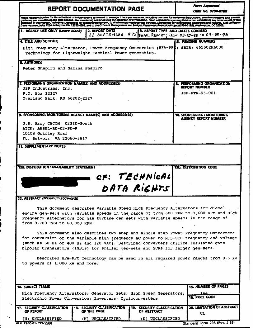
5.8 Technical Data Rights
Rights in technical data, including software, developed under the terms of any contract resulting from proposals submitted in response to this solicitation shall remain with the contractor, except that the government shall have the limited right to use such data for government purposes and shall not release such data outside the government without permission of the contractor for a period of four years from completion of the project from which the data was generated unless the data has already been released to the general public. However, effective at the conclusion of the four-year period, the government shall retain a royalty-free license for government use of any technical data delivered under an SBIR contract whether patented or not. See FAR clause 52.227-20, "Rights in Data - SBIR Program" and DFARS 252-227-7013 alternate 11(3) "GovernmentPurpose License Rights".
Table of Contents Page
Results of the Phase I Work 4
Engines 5
Diesel engines 5
The rotary engines 11
Gas turbine engines 15
Conclusion 19
Alternators r 20
Conventional alternators 20
High Frequency, Low Speed Alternators 20
High Frequency, High Speed Alternators 24
Permanent Magnet (PM) Alternators 26
Variable Speed Alternators 36
Frequency Converters 36
Efficiency 36
Output Waveform 39
Conclusion and Recomendations 41
References and Bibliography 42
Appendixes
Appendix A.
ADDendix B
Appendix C
Appendix D
Appendix E
Appendix F
Appendix G
Appendix H
Appendix I
Appendix J
Appendix K
Appendix L
Appendix M
Appendix N
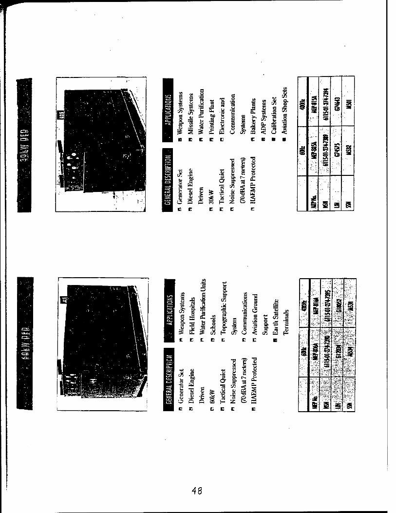
Military MEP generators 47
Conventional variable frequency converters (EMS) 52
Main components for inverters, IGBTs modules (Powerex) 56
Main components for rectifiers, Diode Bridge modules (Powerex) 65
Heat Sinks (Aavid Engineering) 85
Westinghouse 200 HP high speed motors 87
High speed alternator components (KaVo EWL) 94
Diesel engines for 5 and 10 kW gen-sets (Lister-Petter) 99
Diesel engines for 15 kW gen-sets (Isuzu) 107
Diesel engines for 60 kW gen-sets (Detroit Diesel) 111
Rotary engines (Rotary Power International) 117
Small gas turbine engines (Sundstrand Power Sistems) 126
Small gas turbine engines (Allison) 133
High speed bearings 140
3
C. Results of the Phase I Work
The topic for this project:
TOPIC: A94-072 TITLE: High Frequency Alternator. Power Frequency Conversion (HFA-PFC) Technology for Lightweight Tactical Power Generation
Point of Contact: CECOM
CATEGORY: Advanced Development
OBJECTIVE: To explore the potential for generator set size and weight reduction through the use of integrated power components. Components include a lightweight. High Frequency Alternator (HFA) coupled with Power Frequency Conversion (PFC) components to produce MIL-STD power (such as 60 Hz, 120 VAC). A control system would maintain the proper output frequency and voltage for transient and steady state load conditions and changing engine speed.
DESCRIPTION: There exists excellent potential for reducing the size and weight of DOD tactical generator sets using the HFA-PFC concept. In addition to potential weight reductions, this concept de-couples the output frequency from engine speed so that the engine can run at a speed dictated by the operational environment (higher speeds for maximum power or lower speeds for maximum fuel efficiency and reliability). Such performance flexibility and size/weight reductions would improve the operational performance of the gen- sets due to improved deployability and mobility, and reduced handling requirements. Such performance goals match Army requirements and scenarios for highly dynamic "shoot and scoot" situations expected in future conflicts. A weight driver for current DoD gen-sets is the 60 Hz alternator which is generally driven at 1,800 rpm by the engine. Alternator size and weight decrease dramatically when speed and frequency are increased. Engine power density can also be increased because the engine can be run at its optimum power speed for high power loads. The PFC components condition alternator power to produce MIL-STD frequency and voltage (such as 60 Hz and 120 VAC) independent of engine speed. Commercial 1,800 rpm, 60 Hz alternators represent static technology with little performance improvements foreseeable. Power semiconductors (the major component of the PFC) are a rapidly advancing technology with excellent potential for further size/weight reductions in the future.
Phase I: The contractor shall determine optimum HFA-PFC design options for the following power ranges: 5-30 kW, 30-100 kW and i00-l,000 kW. Determine the optimum HFA design and the optimum power semiconductor technology and topology for the given power ranges.
Phase II: The Government can determine the optimum power range(s) to be explored during Phase U based on Phase I results analysis and review.) The contractor shall fabricate and test prototype full scale or sub-scale (as appropriate) versions of the HFA-PFC. The mobility and deployability benefits due to weight reductions shall be quantified along with studies to determine producibility and logistics issues associated with HFA-PFC based gen-sets.
Potential Commercial Market: HFA-PFC technology would be applicable to the commercial gen-set market segments where size/weight and/or fuel efficiency are key concerns. The major life cycle cost element of commercial gen- sets is fuel cost, so being able to produce 60 Hz at the most efficient engine speed could be a distinct advantage.
Current military gen-sets use 60 Hz or 400 Hz brushless alternators that are generally driven by diesel engines at 1,800 or 2,000 RPM, respectively. Diesel engines are used because they are the best in fuel economy compared to all other existing engines.
Diesel fuel storage and handling is less hazardous than with gasoline, and logistic burdens are reduced by having a common fuel for a large number of users.
Some quantity of military gen-sets with gas turbine engines exists, for example, 60 kW gen-set EMU-30/E (MEP-404B), but their specific fuel consumption (S.F.C.) is about 1.4 Ibs/HPhr compared to .375 Ibs/HPhr for diesel gen-sets [1].
The existing price of the small gas turbine engines is over $120,000 for each unit, or more than ten times more expensive compared to all other types of existing engines, including rotary engines [2].

The existing military gen-sets with gas turbine engines are used mostly by the US Air Force, but based on a new global situation when future wars will be similar to the Persian Gulf War, the US Army should have the same mobility as the US Air Force, and military gen-sets with gas turbine engines should be taken into consideration.
Army wide assets of mobile electric power generators with diesel engines in the range from 0.5 kW to 200 kW are shown on the Chart 1, page 6 [3].
Engines
The existing Tactical Quiet Generator Sets (TQGs) with diesel engines have a constant shaft speed of 1,800 RPM and direct coupling of the engine with an alternator.
The technical data about the existing TQGs in the power range from 5 kW to 60 kW is shown in the Table 1, page 7 [4,5,6].
The current manufacturer of these TQGs is Libby Corp., Kansas City, Missouri.
The technical data about the engines manufactured by John Deere and used in existing 30 kW and 60 kW TQGs isn't available because their diesels don't comply with military engine emission regulations and, at least for 5 years, will not be available for military applications or, at least, for new design. We got this information from Mr. Julio De Silva, a manager with John Deere.
Moreover, he also said that two gentlemen, Mr. Jerry Wilson and Col. James Cross, from DoD Project Manager Mobile Electric Power now are working with John Deere to somehow solve the problem.
Diesel engines are the best in fuel economy. However, the weight to HP ratio for the diesel engines is from 6-8 lbs/HP (for a few hundred HP diesels) to 9-10 lbs/HP (for small diesel engines with HP less than 100 HP) [7].
Small diesel engines with HP less than 30 HP have a specific fuel consumption (S.F.C.) of 0.43-0.440 Ibs/HPhr. Larger diesel engines with HP above 30 HP up to 1,500 HP (1,000 kW gen-sets) have a specific fuel consumption (S.F.C.) of 0.350-0.375 Ibs/HP-hr [4,5].
Some technical data about the diesel engines utilized in existing Tactical Quiet Generator Sets (TQGs) in the power range from 5 kW to 15 kW is shown in the Table 2, page 8. These gen-sets have a fixed rotor speed of 1,800 or 2,000 RPM because of requirement for constant output frequency of 60 Hz or 400 Hz.
The calculation of the maximum continuous output power of the gen-sets at the maximum continuous engine speeds (Table 2, page 8) were based on an assumption that output voltage and frequency could be converted to the desired voltage and frequency without any losses.

'5^9^^^^^^^^™"^7ÖT 704 2356 POWER GEN DIV 1002
CO CD 05
CO <r O
cc
csfc □c CO LU CO
O w Q-9 9^ h- ^
UJ <
111 UJ _J Cß O
«r O u_
< D
CO H LU
CO CO
H CVI LU CO
CO O
>- ^~
2 < CC o < f-
Q Z < er o
6

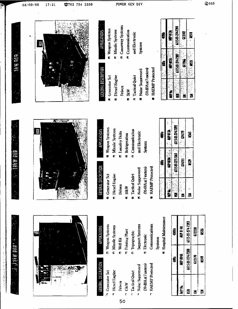
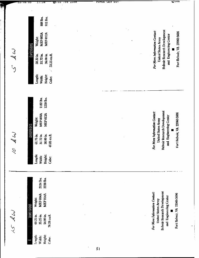
Table 1.
Rated Power, kW and Frequency, Hz
MEP No. Size, L x W x H, inches Size, Cube, cu.ft.
Weight, lbs
5 kW, 60 Hz*1 MEP-802A 50.32x31.72x36.00 33.25 888
5 kW, 400 Hz MEP-812A 50.32x31.72x36.00 33.25 911
10 kW, 60 Hz*1 MEP-803A 61.75x31.72x36.00 40.81 1182
10 kW, 400 Hz MEP-813A 61.75x31.72x36.00 40.81 1220
15 kW, 60 Hz*2 MEP-804A 69.25 x 35.25 x 54.00 76.28 2124
15kW, 400 Hz MEP-814A 50.32x31.72x36.00 76.28 2238
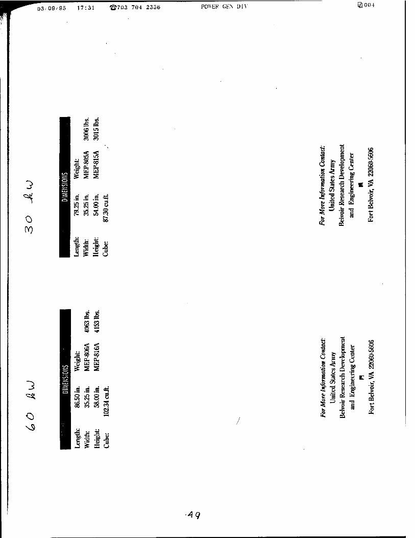
30 kW, 60 Hz*3 MEP-805A 79.25 x 35.25 x 54.00 87.30 3006
30 kW, 400 Hz MEP-815A 79.25 x 35.25 x 54.00 87.30 3015
60 kW, 60 Hz*3 MEP-806A 86.50 x 35.25 x 58.00 102.34 4063 60 kW, 400 Hz MEP-816A 86.50 x 35.25 x 58.00 102.34 4153
NOTES: *1 Diesel engines manufactured by Lister-Petter, Inc.; *2 Diesel engines by Isuzu Diesel of North America; *3 Diesel engines by John Deere Engine Works;
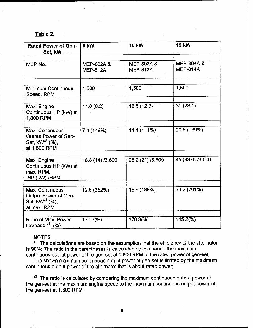
Table 2.
Rated Power of Gen- Set, kW
5kW 10 kW 15 kW
MEP No. MEP-802A & MEP-812A
MEP-803A & MEP-813A
MEP-804A & MEP-814A
Minimum Continuous Speed, RPM
1,500 1,500 1,500
Max. Engine Continuous HP (kW) at 1,800 RPM
11.0(8.2) 16.5(12.3) 31 (23.1)
Max. Continuous Output Power of Gen- Set, kW*1 (%), at 1,800 RPM
7.4(148%) 11.1 (111%) 20.8(139%)
Max. Engine Continuous HP (kW) at max. RPM, HP (kW) /RPM
18.8(14)/3,600 28.2(21)/3,600 45 (33.6) /3.000
Max. Continuous Output Power of Gen- Set, kW*1 (%), at max. RPM
12.6 (252%) 18.9(189%) 30.2(201%)
Ratio of Max. Power Increase *2, (%)
170.3(%) 170.3(%) 145.2(%)
NOTES: *1 The calculations are based on the assumption that the efficiency of the alternator
is 90%; The ratio in the parentheses is calculated by comparing the maximum continuous output power of the gen-set at 1,800 RPM to the rated power of gen-set;
The shown maximum continuous output power of gen-set is limited by the maximum continuous output power of the alternator that is about rated power;
** The ratio is calculated by comparing the maximum continuous output power of the gen-set at the maximum engine speed to the maximum continuous output power of the gen-set at 1,800 RPM.
The losses in frequency converters could be about 2-6% for AC-DC-AC type of converters and about 1-2% for zero switching AC- AC type of converters.
The rated output power of all engines is listed by manufactures with a tolerance of +/- 5%. In this case, the losses of about 1-2% could be omitted.
From Table 2, page 8, it can be seen that the maximum continuous output power of the gen-sets at maximum engine speeds of 3,000-3,600 RPM could be about twice more than the gen-set's rated output power at an engine speed of 1,800 RPM. That is, the utilization of the High Frequency Alternator, Power Frequency Conversion (HFA- PFC) Technology for Lightweight Tactical Power Generation can double the maximum continuous output power while the size and weight of gen-sets could be the same or even lighter and smaller compared to conventional TQG gen-sets.
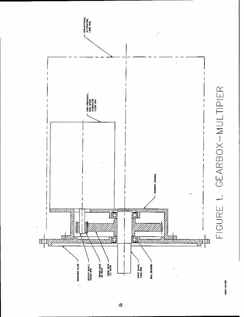
The size and weight of the small TQGs in the power range from 5 kW to 15 kW could be the same or lighter and smaller because conventional alternators will be replaced with an assembly of the gearbox multipliers and the high speed, high frequency alternators which will be mounted as shown on Figure 1, page 10 The shown assembly will be much lighter than the conventional 1,800 RPM alternator. Even after the installation of the frequency converters, the size and weight of the existing 5-15 kW gen-sets will be about the same as existing military TQGs or even lighter and smaller.
Gen-sets larger than 15 kW, based on the HFA-PFC Technology, will be significantly smaller and lighter compared to conventional gen-sets of the same rated power.
Alternators can have a continuous speed of 3,600 RPM to provide a 60 Hz output without any technical problems, but a speed of 3,600 RPM is too high for conventional military grade heavy duty diesels with BHP more than 50 HP.
Some small diesel engines with BHP in the range from 10 HP to 40 HP can run at a continuous speed of 3,600 RPM, for example, LPW line of diesels from Lister-Petter and KC, KR line of diesels from Isuzu Diesel of North America, but their specific fuel consumption (S.F.C.) at 3,600 RPM is 15% higher compared to their S.F.C. at 1,800 RPM [4,5]
Medium size diesel engines with BHP in the range from 40 HP to 250 HP have the maximum continuous speeds of about 2,500-3,000 RPM [5].
Diesel engines with BHP in the range of 250 HP and up have maximum continuous speeds of about 1,800-2,300 RPM [7,17].
All the advantages of implementation of the HFA-PFC Technology in gen-sets with diesel engines can be achieved only if some kind of speed multiplier between the engine and alternator would be utilized as shown on Figure 1, page 10.
From all the possible types of the speed multipliers only the gearbox multipliers have the required reliability even if they could be more expensive compared to other types of speed multipliers.
Y///////////A
BE i^\\\\\^
im x r < S
v//////////^iihii^y/////////////y
^^m^^mmm^.'^
LJ
CL
X o m cr < Ld o
LU
Z) o
10
The gearbox multiplier that is shown on Figure 1, page 10,has an output speed/input speed ratio of 7 and 11 kW output power to drive 10 kW alternator at 12,600 RPM. The diesel continuous crankshaft speed is 1,800 RPM.
At a continuous crankshaft speed of 3,600 RPM, an alternator will have a shaft speed of 25,200 RPM and continuous output power of 18.9 kW. That is, almost twice more compared to a conventional 10 kW gen-set.
The gearbox multiplier that is shown on Figure 1, page 10, isn't just a sketch to illustrate the idea of the HFA-PFC Technology. This is rather a preliminary assembling drawing with all the necessary dimensions based on preliminary calculations. The mentioned drawing can be used either for a prototype with welded housing or later for casted housing.
If for any reason, the mentioned alternator speed range of the multiplier will be too high, this range could be shifted to lower speeds with some compromise in the size and weight.
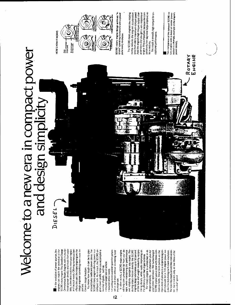
The rotary engines have a weight about twice lighter and a size about twice smaller compared to diesel engines as shown on page 12.
Some information about rotary engines from Rotary Power International (RPI) is enclosed shown on pages 13 and 14.
RPI rotary engines have a maximum fuel efficiency in the speed range from 3,500 RPM to 5,000 RPM and a maximum rated power at the shaft speed of 6,000 RPM.
Their minimum specific fuel consumption (S.F.C.) is 0.450 Ibs/HP-hr or equivalent to diesel, as stated in their catalog.
However, this is true only for small engines with BHP in the range from 10 HP to 40 HP when diesel engines have a S.F.C. of 0.440 Ibs/HP-hr.
Larger diesel engines have a S.F.C. of 0.350-375 Ibs/HP-hr. Larger rotary engines have a S.F.C. of about 25% higher compared to diesel
engines.
The rated engine power for the first generation of RPI rotary engines is shown on pages 13 and 14. The rated engine power of the second generation (the "power growth version") will be twice as much as the rated engine power for the first generation and is shown in parentheses on page 13.
The mentioned rotary engines were developed by RPI for military applications, and engines of the first generation are scheduled for production in 1997.
However, the development of the engines of the second generation is beyond schedule and their availability might be expected sometime in 1998-99 or beyond (in July 1992, the RPI planned to introduce them in 1995).
li
(ft c O H5
: o at a
"- w ES x
III! - 2 E ä : as g it j= a > -* *~ w
= S UJ
ig c°g
I §g 1 : </. *- o : gg.a ; ao
2Sfi Sie Säg IS!
I CD in ÖS;
cB S i = .£
c O) n: m x: c
ill 5 ä ^ = ag
E tue o s a ü en
e s^ g? .9« » » 2>
c u a -o UJ
.1 g QD 3
geS frf s £ 2 e
<" JZ
81 £ =3
&s •* as jr "> .^ Cv QJ „
i Mi üi C (TJ * « b Si Q)
■^ TC QC -S "
I e & S J2 £ 8s?
ibia cu —
as ■o -o
2 13
» =
g-3 Ü E ~ ro — t/i ir ^ tffl c
5 * w
S-o SIS« lie
s 3 ro
E £ 3 CO
» E
B 9 .H" TO
w -r- O L_ 3 m ^ — t- —- "- C= r-
'2 S o»*!-0
£ CL) M C 3 "^ £ i/i re *D Cu o i_i
J3 Sr QB
. o <" ■ - >. ^ |IS Tj G >- Qfl£ CJ 3 QJ -C
3£
"> E? 8 ^ 3 TO CU S? Q.-5 £ ™ c^£-5
ig sä .5 H- -t i^
in o ra it
C C C Cl ■E o g c
I = Id S
. QJ .E QJ
C CJ 3
^ B-Si
'SfeE <T3 "^ JE
c PC c
Is I
El ■c o
I re
1 _ cj ~ i: >
Q> O U 3
re C — £ ö Si C .:= 3 Cu CO. C
C *= — i=
12
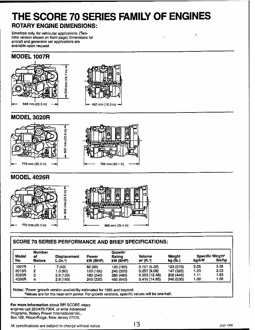
THE SCORE 70 SERIES FAMILY OF ENGINES ROTARY ENGINE DIMENSIONS: Envelope only, for vehicular applications. (Two- rotor version shown on front page) Dimensions for aircraft and generator set applications are available upon request.
MODEL 1007R
465 mm (18.3 in) -H
MODEL 3020R
MODEL 4026R
898 mm (35.4 in)
SCORE 70 SERIES PERFORMANCE AND BRIEF SPECIFICATIONS:
Model No.
Number of Rotors
Displacement L(in.3)
Power kW (BHP)
Growth1
Rating kW (BHP)
Volume m3 (ft.3)
Weight kg (lb.)
Specific Weight2
kg/kW lbs/hp
1007R 2013R 3020R 4026R
1 2 3 4
.7(40) 1.3(80) 2.0(120) 2.6(160)
60 (80) 120(160) 180(240) 240 (320)
120(160) 240 (320) 360 (480) 480 (640)
0.151 (5.32) 0.257 (9.08) 0.353(12.46) 0.415(14.65)
123(270) 147(325) 200 (440) . 240 (530)
2.05 3.38 1.23 2.03 1.11 1.83 1.00 1.66
Notes: 'Power growth version availability estimated for 1995 and beyond. 'Values are for the near-term power. For growth versions, specific values will be one-half.
For more information about RPI SCORE rotary engines call 201/470-7004, or write Advanced Programs, Rotary Power International Inc., Box 128, Wood-Ridge, New Jersey 07075.
All specifications are subject to change without notice. 13 JULY 1992
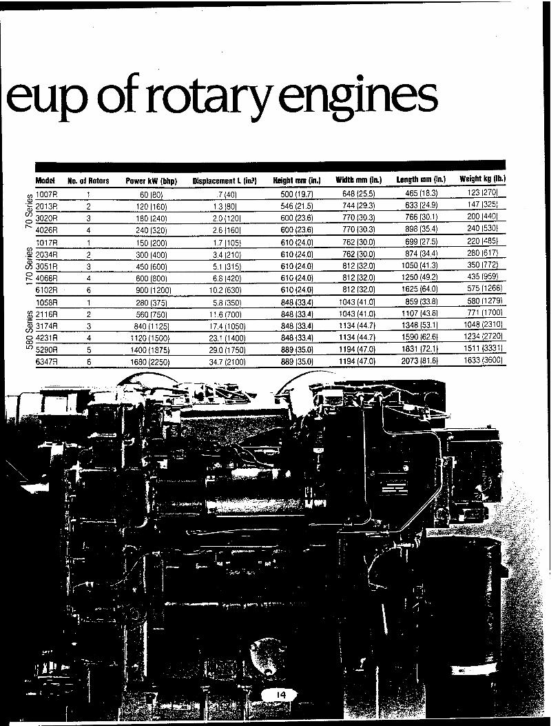
eup of rotary engines Model No. of Rotors Power kW(bhp) Displacement L (in?) Height mm (in.) Width mm (in.) Length mm (in.) Weight kg (lb.)
w 1007R
f 2013R en o I--.
3020R
4026R
1017R
•9> 2034R
$3051R
° 4068R
6102R
1058R
jg2116R
$3174R_
o4231R 00 • 10 5290R
6347R
IP* '*■»-..
60 (80) ■7 (40)
120(160) 1.3(80)
180(240) 2.0(120)
240 (320) 2.6(160)
150(200) 1.7(105)
300 (400) 3.4(210)
450 (600) 5.1 (315)
600 (800) 6.8 (420)
900(1200) 10.2(630)
280 (375) 5.8 (350)
560 (750) 11.6(700)
840(1125) 17.4(1050)
1120(1500) 23.1 (1400)
1400(1875) 29.0(1750)
1680(2250) 34.7(2100)
500(19.7) 648 (25.5) 465(18.3)
546(21.5) 744 (29.3) 633 (24.9)
600 (23.6) 770 (30.3) 766(30.1)
600 (23.6) 770 (30.3) 898 (35.4)
610(24.0) 762 (30.0) 699 (27.5)
610(24.0) 762 (30.0) 874 (34.4)
610(24.0) 812(32.0) 1050(41.3)
610(24.0) 812(32.0) 1250(49.2)
610(24.0) 812(32.0) 1625(64.0)
848 (33.4) 1043(41.0) 859 (33.8)
848 (33.4) 1043(41.0) 1107(43.6)
848 (33.4) 1134(44.7) 1348(53.1)
848 (33.4) 1134(44.7) 1590(62.6)
889(35.0) 1194(47.0) 1831 (72.1)
889 (35.0) 1194(47.0) 2073(81.6)
•v ,-*r , ',afe ~-& *'i
123(270)
147(325)
200 (440)
240 (530)
220 (485)
280(617)
350 (772)
435 (959)
575(1268)
580(1279)
771 (1700)
1048(2310)
1234(2720)
1511(3331)
1633(3600)
J'-.f..-'--.-^*. »*«**** : 11 ■-•■■■ ■ • .&g£U**
II» **
t$m
Gas turbine engines with gearbox reducers have a weight to HP ratio of 0.5-1 lbs/HP compared to the weight to HP ratio for the diesel engines that is from 6-8 lbs/HP (for a few hundred HP diesels) to 9-10 lbs/HP (for small diesel engines with HP less than 100 HP) [7].
The gearbox reducers are required because of the very high speeds of the turbine shafts that are over 100,000 RPM for small engines in the power range from 12 HP to 60 HP, about 40-60,000 RPM for engines in the power range from 90 HP to 350 HP, and about 18-22,000 RPM for engines in the power range from to 350 HP to 4,000 HP.
Regenerative gas turbine engines with an output power of more than 300 HP can be comparable to diesel engines in fuel economy [8].
On Figure 2, page 16, 395 HP and 450 HP Ford marine gas turbine engines with gearbox reducers are shown [9]. The first gas turbine engine is suitable for a 230 kW generator set that will have a total weight of approximately 2,900 lbs. compared to the total weight of the 230 kW diesel generator set that is approximately 6,050 lbs., or twice lighter!
If these engines will be used with high speed alternators with direct coupling with turbine shaft, their weight can be significantly reduced because of the elimination of gearboxes.
These engines have a S.F.C. of about 0.440 Ibs/HPhr including losses in their gearboxes compared to 0.375 Ibs/HP-hr for diesel engines of the same power. Their S.F.C. is only 14% higher, and this difference could be insignificant if we take into consideration the requirement of the high level of mobility equal to the mobility of the US Air Force.
The production cost of the turbine engines might be less than the cost of production of the conventional gasoline engines in comparative quantities [10]. General Motors, Ford, Chrysler, and other car manufacturers have a full line of the turbine engines that were designed for automotive applications.
The current very high price of military grade turbine engines can be explained by the fact that these engines are manufactured in very small quantities (from a few units to a few dozen). Quantities of a few hundred units are very rare.
In Table 3 on page 17 the engine and alternator speeds for gas turbine engine gen- sets from 15 HP to 10,000 HP are shown.
For the illustration of all the advantages of implementation of the HFA-PFC Technology in gen-sets with gas turbine engines, lets compare existing conventional military 60 kW, 400 Hz gas turbine gen-set type MEP with proposed gas turbine engine gen-set based on the HFA-PFC Technology.
15

COMPACT SIZE MAKES INSTALLATION EASY.
FORD TURBINE PERFORMANCE FOR MARINE APPLICATIONS.
«no <aoo MOO .*oo !m „o- .„„ „,,
*«r(orm«ne« curvo«, Ford 380M-2OOO-A engirt*.
u> in m .mo j«» .-«a, /—, ' '■' «■■»■
Porformanc» cunrM, Ford 420M-2000-A .ngm«.
Figure 2. Ford gas turbine engine
J6
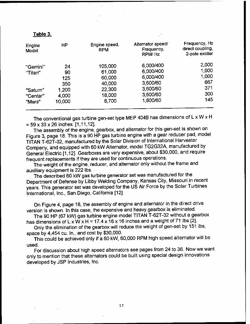
Table 3.
Engine HP Model
"Gemini" 24 "Titan" 90
125 350
"Saturn" 1,200 "Centar" 4,000 "Mars" 10,000
Engine speed, Alternator speed/ Frequency, Hz RPM Frequency, direct coupling,
RPM/ Hz 2-pole exciter
105,000 6,000/400 2,000
61,000 6,000/400 1,000
60,000 6,000/400 1,000
40,000 3,600/60 667
22,300 3,600/60 371
18,000 3,600/60 300
8,700 1,800/60 145
The conventional gas turbine gen-set type MEP 404B has dimensions of L x W x H = 59x33x26 inches. [1,11,12].
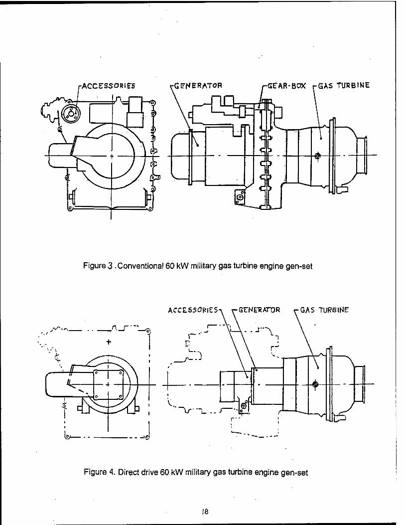
The assembly of the engine, gearbox, and alternator for this gen-set is shown on Figure 3, page 18. This is a 90 HP gas turbine engine with a gear reducer pad, model TITAN T-62T-32, manufactured by the Solar Division of International Harvester Company, and equipped with 60 kW Alternator, model TG2G32A, manufactured by General Electric [1,12]. Gearboxes are very expensive, about $30,000, and require frequent replacements if they are used for continuous operations.
The weight of the engine, reducer, and alternator only without the frame and auxiliary equipment is 222 lbs.
The described 60 kW gas turbine generator set was manufactured for the Department of Defense by Libby Welding Company, Kansas City, Missouri in recent years. This generator set was developed for the US Air Force by the Solar Turbines International, Inc., San Diego, California [12].
On Figure 4, page 18, the assembly of engine and alternator in the direct drive version is shown. In this case, the expensive and heavy gearbox is eliminated.
The 90 HP (67 kW) gas turbine engine model TITAN T-62T-32 without a gearbox has dimensions ofLxWxH = 17.4x16x16 inches and a weight of 71 lbs [2].
Only the elimination of the gearbox will reduce the weight of gen-set by 151 lbs, space by 4,454 cu. In., and cost by $30,000.
This could be achieved only if a 60 kW, 60,000 RPM high speed alternator will be used.
For discussion about high speed alternators see pages from 24 to 36. Now we want only to mention that these alternators could be built using special design innovations developed by JSP Industries, Inc.
17
-ACCESSORIES -G AERATOR GEAR-BOX rGAS TURBINE
c *——
\
^_
Figure 3 .Conventional 60 kW military gas turbine engine gen-set
ACCES50RIE:S-V rGENERATOR rGAs TURBINE
l*_.. \£f
Figure 4. Direct drive 60 kW military gas turbine engine gen-set
18
Conclusion: For the short term planning (2-5 years), the existing TQGs could be replaced only by improved gen-sets using existing diesel engines if the fuel economy is the main requirement.
However, other types of engines, rotary and gas turbine, should be taken in consideration for the long term planning (5-10 years) because intensive research and development (R & D) programs conducted by Rotary Power International, Inc. for improvement of the rotary engines under contracts with the Department of Defense and R&D programs conducted by the Allison Engine Company for improvement of the gas turbine engines under contracts with the Department of Energy, NASA, and General Motors Corp. exist.
The Ford Company has similar R&D programs for improvement of the gas turbine engines under contracts with the Department of Energy and NASA.
The targets of all the mentioned programs are rotary or gas turbine engines with S.F.C. and price equivalent to S.F.C. and price of the diesel engines.
However, even in the case of complete success, the rotary engines from Rotary Power International, Inc. will have minimum S.F.C. of 0.450 Ibs/HPhrcompared to 0.375 Ibs/HPhrfor the existing diesels, or 20% higher. The estimated production price of the rotary engines will be in the range of $12-14,000 each for small engines.
The ceramic gas turbine engines from Allison Engine Company, in the case of complete success, will have S.F.C. and price equivalent to existing gasoline car engines. This very limited information was provided by Mr. Duge, Deputy Program Manager for Allison Engine Company. Mr. Duge declined to disclose the exact S.F.C, turbine shaft speed, and other technical information about their ceramic gas turbines as company confidential information.
All mentioned R&D programs are long term programs with multi-million dollar budgets. The expected production is scheduled not earlier than the end of this decade.
In the near term, only diesel engines will be available as field tested engines with strong positive information about their reliability and low fuel consumption.
However, only gen-sets with gas turbine engines are a promising solution if size and weight are the main requirements, and there is a very strong reason to build a prototype utilizing existing gas turbine engine for demonstration of all the advantages of High Frequency Alternator, Power Frequency Conversion (HFA-PFC) Technology for Lightweight Tactical Power Generation.
19
Alternators
Conventional alternators, in the conventional version with slip rings and brushes for exciter circuit, are not reliable enough for military applications, and they were replaced by brushless alternators.
The brushless AC alternator actually consists of two alternators on the common shaft. The main alternator generates the output AC current. A smaller alternator, the exciter, generates an AC current that, after rectification, is used for exciter of the main alternator.
Conventional brushless alternators have rotor speeds of up to 6,000 RPM. At speeds above 6,000 RPM centrifugal forces might lead to the displacement of the rotor armature, disbalance of the rotor masses, increase of vibrations, and finally, damages to the alternator.
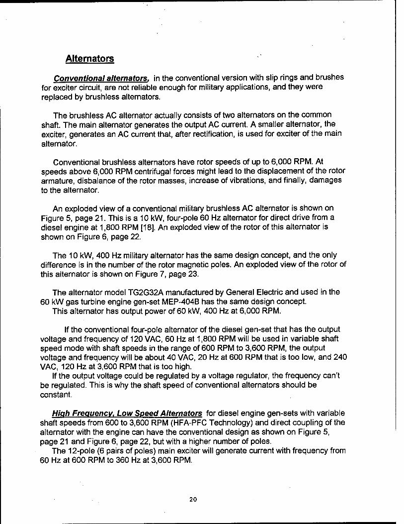
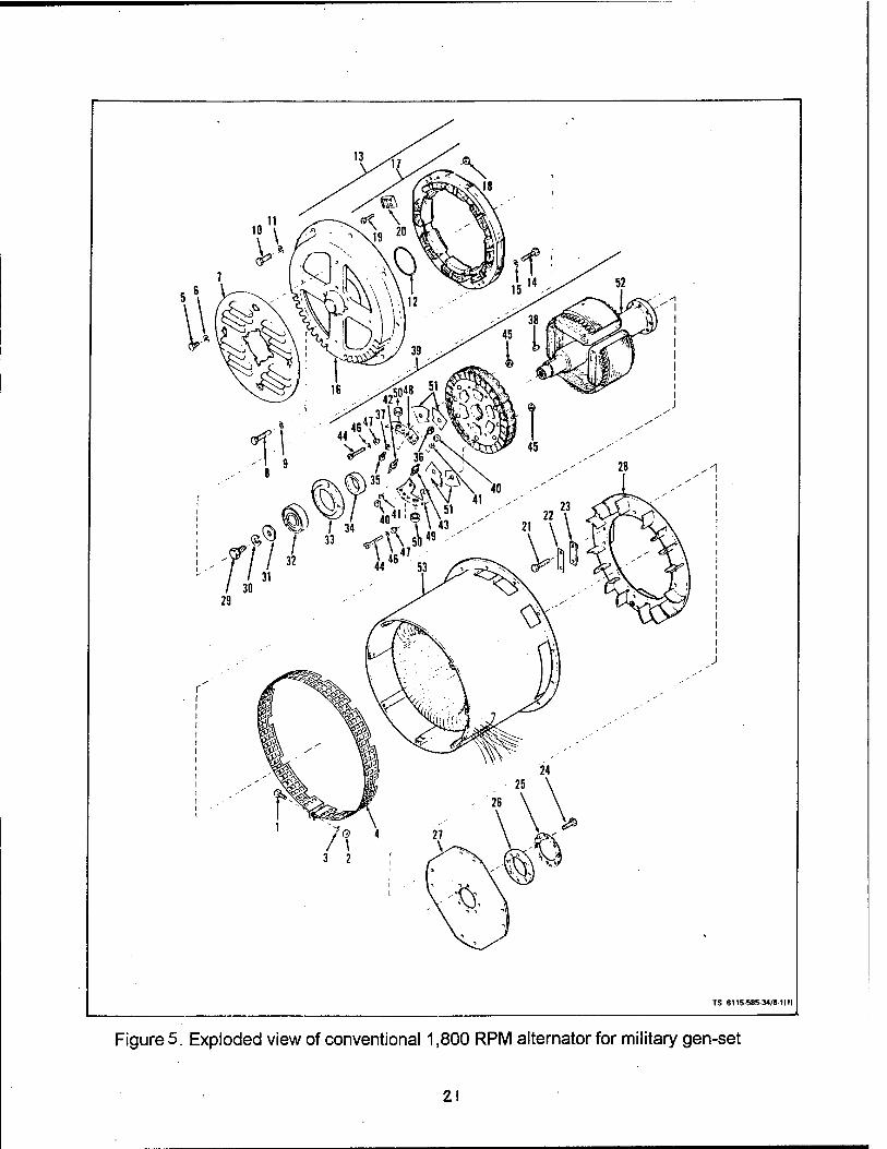
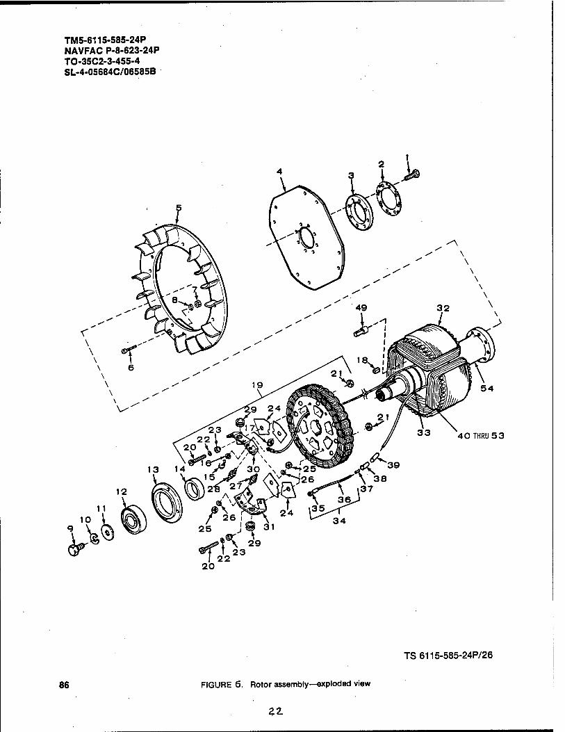
An exploded view of a conventional military brushless AC alternator is shown on Figure 5, page 21. This is a 10 kW, four-pole 60 Hz alternator for direct drive from a diesel engine at 1,800 RPM [18]. An exploded view of the rotor of this alternator is shown on Figure 6, page 22.
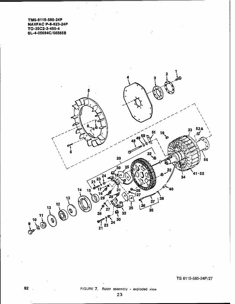
The 10 kW, 400 Hz military alternator has the same design concept, and the only difference is in the number of the rotor magnetic poles. An exploded view of the rotor of this alternator is shown on Figure 7, page 23.
The alternator model TG2G32A manufactured by General Electric and used in the 60 kW gas turbine engine gen-set MEP-404B has the same design concept.
This alternator has output power of 60 kW, 400 Hz at 6,000 RPM.
If the conventional four-pole alternator of the diesel gen-set that has the output voltage and frequency of 120 VAC, 60 Hz at 1,800 RPM will be used in variable shaft speed mode with shaft speeds in the range of 600 RPM to 3,600 RPM, the output voltage and frequency will be about 40 VAC, 20 Hz at 600 RPM that is too low, and 240 VAC, 120 Hz at 3,600 RPM that is too high.
If the output voltage could be regulated by a voltage regulator, the frequency can't be regulated. This is why the shaft speed of conventional alternators should be constant.
High Frequency. Low Speed Alternators for diesel engine gen-sets with variable shaft speeds from 600 to 3,600 RPM (HFA-PFC Technology) and direct coupling of the alternator with the engine can have the conventional design as shown on Figure 5, page 21 and Figure 6, page 22, but with a higher number of poles.
The 12-pole (6 pairs of poles) main exciter will generate current with frequency from 60 Hz at 600 RPM to 360 Hz at 3,600 RPM.
20
TS 6115 585 34/81(11
Figure 5. Exploded view of conventional 1,800 RPM alternator for military gen-set
2!
TM5-6115-585-24P NAVFAC P-8-623-24P TO-35C2-3-455-4 SL-4-05684C/06585B
TS6115-585-24P/26
86 FIGURE 6. Rotor assembly—exploded view
Zl
TM5-6115-585-24P NAVFAC P-8-623-24P TO-35C2-3-455-4 SL-4-05684C/06585B
y>'
41-55
TS6115-585-24P/27
92 FIGURE 7, Rotor assembly - exploded view
23
The 60-pole exciter will generate a current with a frequency from 300 Hz at 600 RPM to 1,800 Hz at 3,600 RPM, etc. However, the multi-pole exciters with a high number of poles will cause some difficulties in design, and twelve pairs is usually the maximum number of exciter poles.
The size and weight of the described high frequency alternator for a 10 kW gen-set with variable shaft speeds from 600 RPM to 3,600 RPM and direct coupling with the diesel engine would be the same as existing 10 kW alternators or more. The power frequency conversion unit will add an additional increase in the size and weight that means that this concept is unpractical.
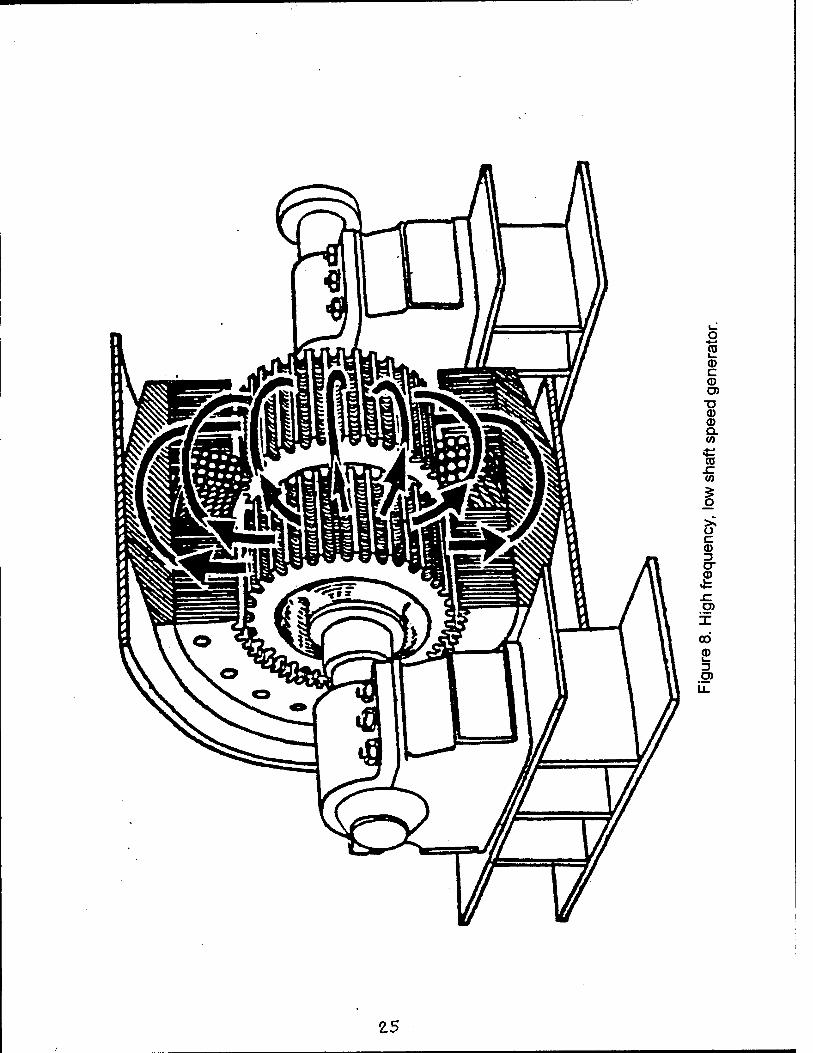
Many types of high frequency generators exist that have low shaft speed. One of them is shown on Figure 8, page 25. However, all of them are larger and heavier than conventional alternators used in the existing gen-sets.
High Frequency. High Speed Alternators. The HFA-PFC Technology can be implemented in diesel gen-sets only if the high frequency, high speed alternators will be used. In this case, the size and weight of the high speed alternators will be in inverse proportion to their speed. To get all the advantages of this concept, a gearbox multiplier should be installed between the engine and alternator as shown on Figure 1, page 10
In this case, the size and weight of the high speed, high frequency alternator, including gearbox, could be much smaller compared to the conventional alternator of the same power at 1,800 RPM.
The gearbox multiplier that is shown on Figure 1, page 10 has an output shaft speed of 12,600 RPM at a rated power of 10 kW (engine crankshaft speed of 1,800 RPM) and speed of 25,200 RPM at a maximum power of 18.2 kW (engine crankshaft speed of 3,600 RPM).
This means that the alternator should be designed for 18.2 kW continuous output power at 25,200 RPM, and conventional brushless alternators couldn't be used for this application.
At speeds above 6,000 RPM centrifugal forces might lead to the destruction of the rotor armature.
From all existing high speed alternators, the most promising are permanent magnet (PM) alternators and wound-rotor, variable speed alternators.
Both of these machines are commonly used as electric motors at comparatively low speeds, under 6,000 RPM.
24
CO l_
<D C CD O) ■a CD © Q. to
CO .c CO
I c CD 23 O" CD
JC O)
00 CD
g>
£5
Permanent Magnet (PM) Alternators actually are conventional brushless DC motors used as generators. In this case, the rotor position sensors and switching power supplies are not required. The rotating magnetic field of the rotor permanent magnets generates a 3-phase AC current in the conventional 3-phase stator winding.
PM alternators don't have any means for output voltage regulation at a fixed rotor speed. The output voltage and frequency could be hardly regulated by change of the rotor speed: increase in speed will proportionally increase the frequency and voltage. The output voltage will also depend on a value and kind of load, active or reactive, while the frequency will depend on the shaft speed only.
Conventional permanent magnet (PM) alternators can have power up to 30 kW at speeds up to 3,000 RPM. Smaller alternators have higher speeds.
The usage of bandages might increase the operational speeds up to 60-80,000 RPM. However, all known high speed alternators with bandage devices generate less power and have increased losses compared to conventional devices.
High frequency, high speed alternators for diesel gen-sets based on the HFA-PFC Technology could have speeds up to 20-25,000 RPM. Practically, this limit should be reduced to 12-15,000 RPM because of the utilization of the gearbox speed multipliers and mechanical problems with bearings, rotor balancing, vibrations, noise, heat dissipation, etc.
High speed alternators in the speed range from 20,000 RPM to 120,000 RPM are required for gen-sets with gas turbine engines based on the HFA-PFC Technology in the version without a gearbox reducer between the engine and alternator.
In this case, the problem is that all existing small gas turbine engines have very high turbine rotor speeds to have acceptable specific fuel efficiency.
Some engineering improvements of existing small gas turbine engines developed by JSP Industries, Inc. have been separately proposed.
These improvements were proposed to reduce turbine shaft speeds without compromise in specific fuel efficiency.
However, development of any kind of engines for the HFA-PFC Technology gen- sets wasn't included neither in the Phase I effort, nor the Phase II effort, and we should plan the Phase II effort using only existing engines or engines that are under development by third parties under contracts with the Department of Defense, the Department of Energy, NASA, etc.
Conventional high speed ball bearings could be used at speeds up to 60,000 RPM. This kind of bearings is used in small gas turbine engines. However, the size and weight of the rotor of a matching alternator of the same power and speed is much higher than to the shaft of gas turbine, and special high speed bearings should be used.
26
From the mechanical point of view, high speed PM alternators are the same as high speed induction motors. .
Significant progress was achieved in the development of the high speed electrical motors with a wireless rotor design concept (squirrel cage or solid rotor) [13,15].
This experience can be used for the development of PM alternators. The stators of both machines can have the same type of windings, and the
difference is mostly in the rotor design.
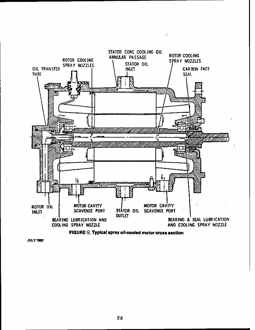
An electrical motors with power range of 50 kW to 200 kW at 28,500 RPM was built by Westinghouse Electric Corporation. This motor is shown on Figure 9, page 28.[15].
An electrical motor with a power of 40 kW at 30,000 RPM was built by Missler. The same design concept was used for a product line of motors from .5 kW to 200 kW at 30,000 RPM and is shown on Figure 10, page 29.[13].
An electrical motor with a power of 30 kW at 60,000 RPM with a squirrel cage rotor was built by another manufacturer. The same design concept was used to build the 60 kW, 60,000 RPM motor. .
A combination of special hydrostatic and hydrodynamic bearings was used in this design that is shown on Figure 11, page 29.[16].
The efficiency of these motors can be increased if ball or roller bearings will be used. However, if these type of bearings wouldn't be available for large size alternators, the hydrostatic and hydrodynamic bearings are available from FAG Bearings Corp., Stamford, Connecticut.
The hydrostatic and hydrodynamic bearings are used when powerful devices are used at high speeds. On Figure 12, page 30, a gearbox multiplicator for centrifugal pumps with powers up to 400 HP and speeds up to 20,000 RPM is shown. These gearboxes are manufactured by Ingersoll-Rand, Phillipsburg, New Jersey.
27
OIL TRANSFER TUBE
ROTOR COOLING SPRAY NOZZLES
STATOR CORE COOLING OIL „ ANNULAR PASSAGE ROTOR COOLING
STATOR OIL SPRAY N0ZZLES
INLET CARBON FACE SEAL
ROTOR OIL INLET
MOTOR CAVITY SCAVENGE PORT
BEARING LUBRICATION AND COOLING SPRAY NOZZLE
MOTOR CAVITY tfOR OIL SCAVENGE PORT
OUTLET BEARING & SEAL LUBRICATION ANO COOLING SPRAY NOZZLE
FIGURE 9. Typical spray oil-cooled motor cross section
JULY1SB2
23
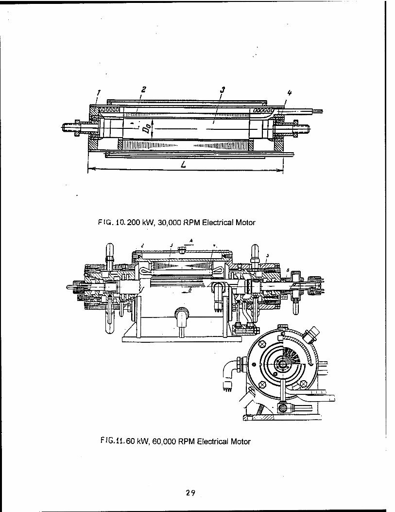
FIG. 10.200 kW, 30,000 RPM Electrical Motor
FIG.ii.60 kW, 60,000 RPM Electrical Motor
29
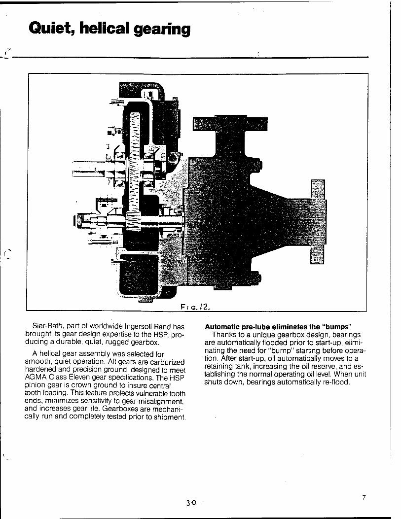
Quiet, helical gearing
FIG. 12.
Sier-Bath, part of worldwide Ingersoll-Rand has brought its gear design expertise to the HSP, pro- ducing a durable, quiet, rugged gearbox.
A helical gear assembly was selected for smooth, quiet operation. All gears are carburized hardened and precision ground, designed to meet AGMA Class Eleven gear specifications. The HSP pinion gear is crown ground to insure central tooth loading. This feature protects vulnerable tooth ends, minimizes sensitivity to gear misalignment, and increases gear life. Gearboxes are mechani- cally run and completely tested prior to shipment.
Automatic pre-lube eliminates the "bumps" Thanks to a unique gearbox design, bearings
are automatically flooded prior to start-up, elimi- nating the need for "bump" starting before opera- tion. After start-up, oil automatically moves to a retaining tank, increasing the oil reserve, and es- tablishing the normal operating oil level. When unit shuts down, bearings automatically re-flood.
30
Some engineering improvements of existing high frequency, high speed PM alternators have been developed by JSP Industries, Inc.
The estimated maximum power of these alternators is about 30-50 kW at 60, 000 RPM.
In 1988 a patent search was performed by Litman, McMahon and Brown Patent Law Office, 1200 Main, suite 1600, Kansas City, MO 64105, for our concept of the High Speed Motor/Alternator. No similar patents were found.
In 1991 patent application was prepared by the same Patent Law Office.
We mentioned about these devices to confirm the feasibility to build the high speed alternators that will have speeds of 60,000 RPM and more and will have the required reliability for military and commercial applications.
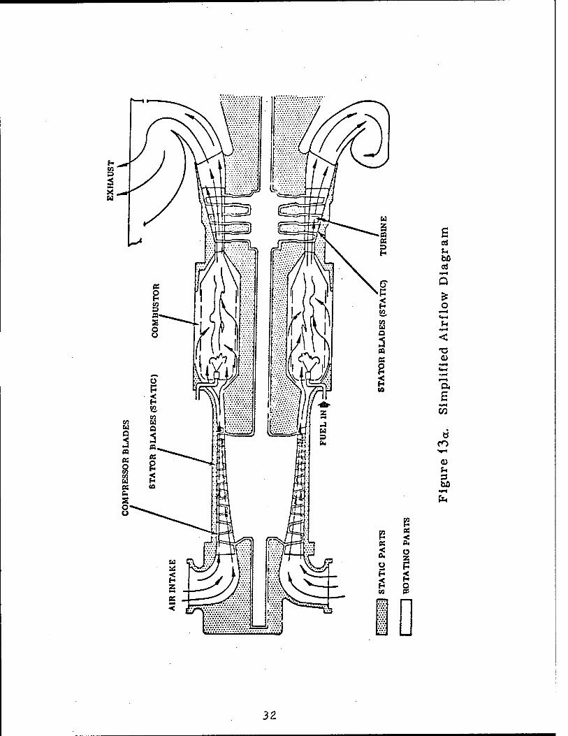
Mechanical schematic of typical conventional gas turbine engines with power over 500 HP and their gearbox reducers are shown on Figure 13a, page 32, and on Figure 13b, page 33 respectively.
An exploded view of the gearbox reducers that are used in gas turbine gen-set MEP-404B is shown on Figure 14, pages 34 and 35.
The next major step in gen-set technology can be done if the high speed alternators with rotor speeds of 60-90,000 RPM will be developed. Expensive gearbox reducers will become unnecessary because these alternators could be coupled directly with the shaft of the gas turbine engine.
Utilization of the reliable electric alternators with direct coupling to the shaft of the turbine engine will eliminate gear box reducers that will reduce size, weight, cost, and will increase reliability of the system.
31
s cd U
o
<
E
Ö CO
u to
32

INPUT --
RING s
H H r K 5 i P, ]
SUN ~ "™" Lii
1ST-STAGE
RING
H u 55
SUN
ZS31
2ND-STAGE Ü RING GEAR (STATIONARY)
SPLlNE SHAFT ENGAGES IN 1ST-STAGE RING GEAR
RING GEAR
1ST-STAGE OUTPUT.
PLANET GEARS (3)
SUN GEAR ACCESSORY DRIVE GEAR •WHEN REQUIRED)
ht-STAGE PLANET GEAR CARRIER OMITTED FOR CLARITY
2NIVSTAGE OUTPUT
PLANET GEAR CARRIER
1 SUN GEAR
2nd-STAGE 0
Figure 136, Reduction Drive Gear Arrangement
33

TO 2G-T62T-14
y
Figure J 4. Cw Reduction and Accessory Drive Assembly (Sheet 1 of 2)
2-21
34

TO 2G-T62T-U
Figure 14. Gear Reduction and Accessory Drive Assembly (Sheet 2 of 2)
2.22
35
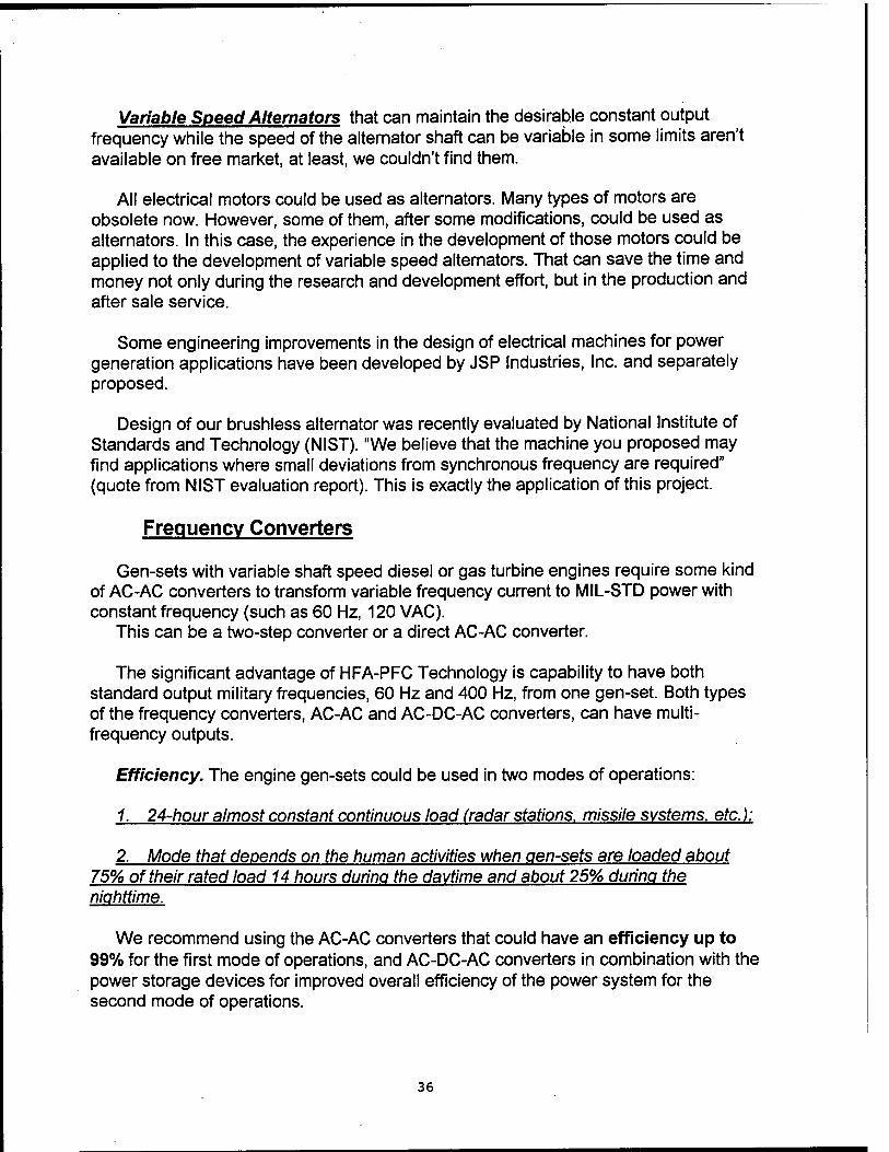
Variable Speed Alternators that can maintain the desirable constant output frequency while the speed of the alternator shaft can be variable in some limits aren't available on free market, at least, we couldn't find them.
All electrical motors could be used as alternators. Many types of motors are obsolete now. However, some of them, after some modifications, could be used as alternators. In this case, the experience in the development of those motors could be applied to the development of variable speed alternators. That can save the time and money not only during the research and development effort, but in the production and after sale service.
Some engineering improvements in the design of electrical machines for power generation applications have been developed by JSP Industries, Inc. and separately proposed.
Design of our brushless alternator was recently evaluated by National Institute of Standards and Technology (NIST). "We believe that the machine you proposed may find applications where small deviations from synchronous frequency are required" (quote from NIST evaluation report). This is exactly the application of this project.
Frequency Converters
Gen-sets with variable shaft speed diesel or gas turbine engines require some kind of AC-AC converters to transform variable frequency current to MIL-STD power with constant frequency (such as 60 Hz, 120 VAC).
This can be a two-step converter or a direct AC-AC converter.
The significant advantage of HFA-PFC Technology is capability to have both standard output military frequencies, 60 Hz and 400 Hz, from one gen-set. Both types of the frequency converters, AC-AC and AC-DC-AC converters, can have multi- frequency outputs.
Efficiency. The engine gen-sets could be used in two modes of operations:
1. 24-hour almost constant continuous load (radar stations, missile systems, etc.):
2. Mode that depends on the human activities when aen-sets are loaded about 75% of their rated load 14 hours during the daytime and about 25% during the nighttime.
We recommend using the AC-AC converters that could have an efficiency up to 99% for the first mode of operations, and AC-DC-AC converters in combination with the power storage devices for improved overall efficiency of the power system for the second mode of operations.
36
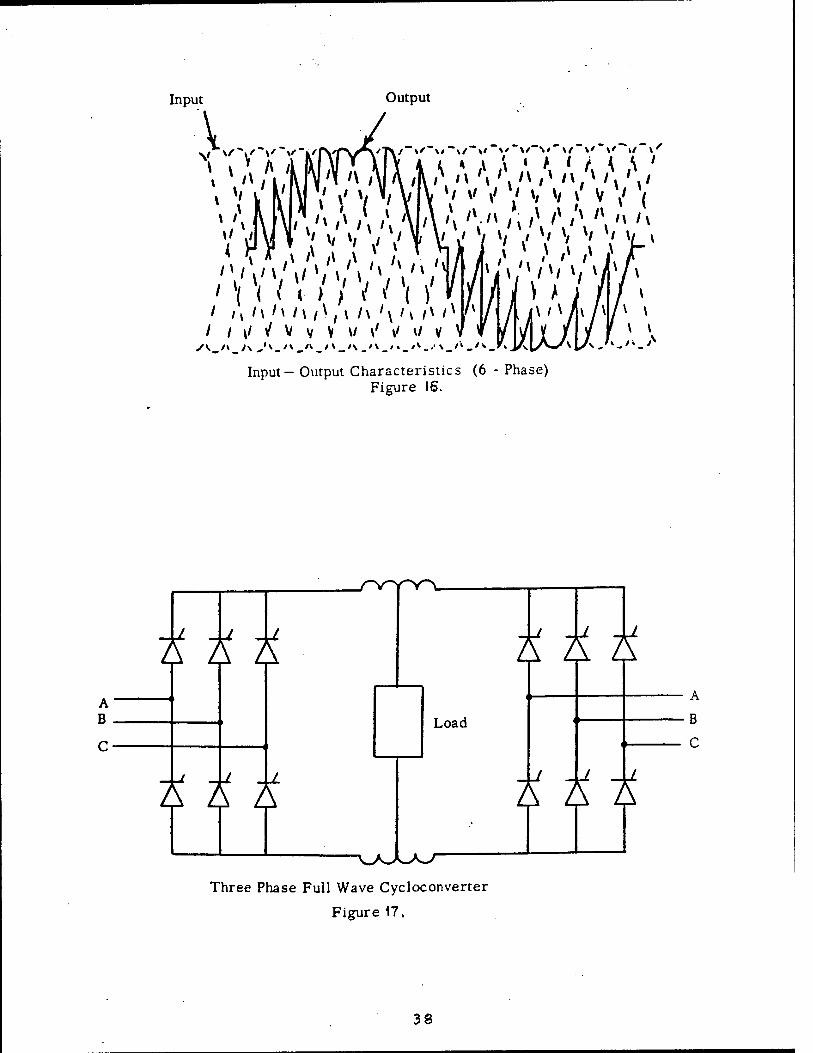
The AC-AC converters convert the high frequency input power from alternator directly to low frequency output power as shown on Figure 16, page 38. The simplified schematic diagram of the AC-AC converter ("Cycloconverter") is shown on Figure 17, page 38.
This type of AC-AC converter can provide an output waveform very close to sine, and have an efficiency of about 94-96%.
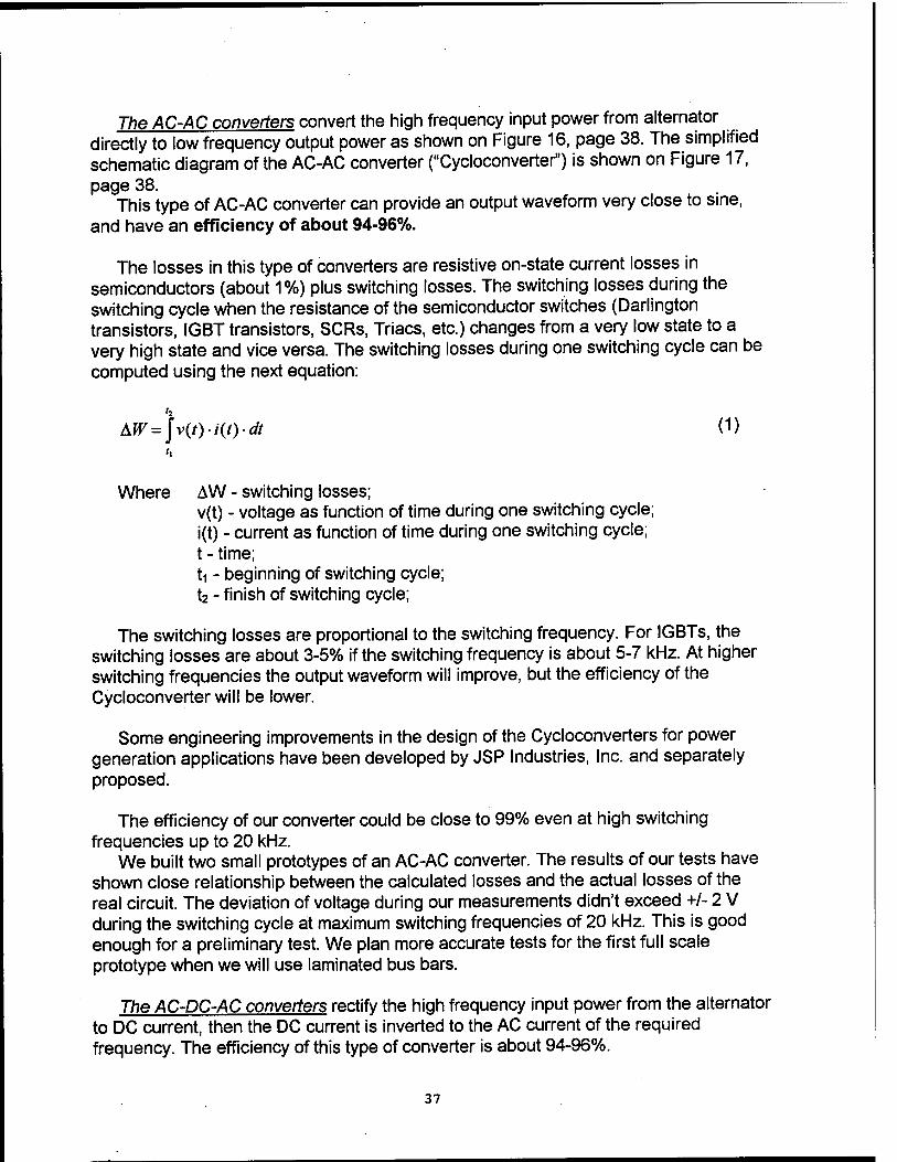
The losses in this type of converters are resistive on-state current losses in semiconductors (about 1%) plus switching losses. The switching losses during the switching cycle when the resistance of the semiconductor switches (Darlington transistors, IGBT transistors, SCRs, Triacs, etc.) changes from a very low state to a very high state and vice versa. The switching losses during one switching cycle can be computed using the next equation:
h
Where AW - switching losses; v(t) - voltage as function of time during one switching cycle; i(t) - current as function of time during one switching cycle; t - time; ti - beginning of switching cycle; t2 - finish of switching cycle;
The switching losses are proportional to the switching frequency. For IGBTs, the switching losses are about 3-5% if the switching frequency is about 5-7 kHz. At higher switching frequencies the output waveform will improve, but the efficiency of the Cycloconverter will be lower.
Some engineering improvements in the design of the Cycloconverters for power generation applications have been developed by JSP Industries, Inc. and separately proposed.
The efficiency of our converter could be close to 99% even at high switching frequencies up to 20 kHz.
We built two small prototypes of an AC-AC converter. The results of our tests have shown close relationship between the calculated losses and the actual losses of the real circuit. The deviation of voltage during our measurements didn't exceed +/- 2 V during the switching cycle at maximum switching frequencies of 20 kHz. This is good enough for a preliminary test. We plan more accurate tests for the first full scale prototype when we will use laminated bus bars.
The AC-DC-AC converters rectify the high frequency input power from the alternator to DC current, then the DC current is inverted to the AC current of the required frequency. The efficiency of this type of converter is about 94-96%.
37
Input
V.... Output
V »' V v V \ V " >' i v<'') v V ( (";>AA'\/\'\'\'\A'\'\/\,\'>'> i ' v V i Vi fc i \ \ i i V r—
' \ \ i < / / / / W " / / / w / / /1 / M /\ >\ /\ /\,\ /\ '\ i\ /v /* '* / L i\iKhrr v
/ / \i 1 V v V w \' \i w v V w / w ¥ / / f v \
( < v < W . . » . I M i\ t\ l\ /\ ,\ I\ *\ i\ /v /* h
I I \l J V v V W \' »/ W V \
Input- Output Characteristics (6 - Phase) Figure IS.
A B
-i -a -j A A A
-u -1 -J. A A A
Load
Three Phase Full Wave Cycloconverter
Figure 17.
kkk
A xz
38
However, the advantage of this type of converter is presence of DC stage that could be connected to any type of energy storage devices (batteries, supercapacitors, flywheel storage devices, etc.). Because of this, the overall efficiency could be significantly increased.
For example, the daily load will be about 75% of the gen-set's rated load for 14 hours during the daytime and about 25% during the nighttime.
In this case the fuel consumption of the conventional 10 kW diesel gen-set will be:
0.405(lbs/HPhr)x7.5 HPx 14 hrs + .640(lbs/HPhr)x2.5 HPx 10 hrs = 58.5 lbs/day.
This computation is based on the data from Table 8, page 6, of our monthly report dated on 15 June 1995.
The fuel consumption of the diesel gen-set with a storage device will be:
.388 (Ibs/HPhr) x 10 HP x 12.5 hrs = 48.5 lbs/day, or about 10 lbs/day less compared to a conventional gen-set.
In this computation we didn't count losses in the energy storage device. We also assumed that the daily load will be about 75% of the gen-set's rated load for 14 hours during the daytime while. More than likely, during those 14 hours the load will drop below 75% many times. The actual savings in fuel consumption might be about 15- 25%. That means that the transportation of the energy storage devices during military field operations is reasonable if the gen-sets will be used without movement for 2-3 weeks. In this case the weight of the saved fuel after 2-3 weeks will exceed the weight of the energy storage devices.
For more powerful diesel gen-sets, the usage of the energy storage devices could be even more efficient because their capacity increases faster than their weight, particularly for flywheel storage devices.
Output Waveform. The typical voltage waveform requirements for military gen-sets (60 kW alternator specification, US Air Force document No. 68A23340, page 10):
a. The 5-th harmonic shall not exceed 1.5% of the fundamental; the 7-th harmonic shall not exceed .75%; no other single harmonic shall exceed .5% of the fundamental.
b. The total harmonic content (square root of the sum of the squared values of all harmonics) shall not exceed 1.73%;
c. The crest factor shall be not more than 1.442 or less than 1.386.
All semiconductor frequency converters could be divided into two major groups:
39
1. Current source converters. This group of frequency converters designed to supply power to known constant load, usually equal to the rated power of the converter. In most cases it is an induction AC motor or transformer. The waveform of the output current in induction loads will be very close to sine, and any additional filtering of the output current isn't required.
2. Voltage source converters. This group of frequency converters designed to supply power to an unknown load, usually random combination of resistive, inductive, and capacitive loads from fraction to 125% of the rated power of the converter.
We believe that the general purpose military gen-sets based on HFA-PFC Technology should have the voltage source type of converters.
The output of all switching converters is some combination of voltage pulses.
For Pulse Width Modulated (PWM) type of converters with 5 pulses/half-cycle (600 Hz PWM control frequency) the output voltage and output current for inductive load (AC induction motor) are very close to sine, and only small ripples could be seen on the oscilloscope (3-phase, 10 HP converter with output frequency range from 3 to 90 Hz manufactured by Polyspede Electronics Corp.). The hardly visible high frequency ripples could be easily filtered, if required.
The increased rate of a PWM switching signal could improve the waveform further. We plan to increase the rate up to 40 pulse/half-cycle.
Another way to improve the output waveform is utilizing the microprocessor to generate the output waveform in real-time using feedback from the output voltage, current, power factor, etc. This system is used in C3+ Series of adjustable frequency converters manufactured by EMS, Fairfield, Ohio. We plan to use a similar technology in our voltage source type converters.
The voltage source type converters should have internal filters to provide the required waveform for any kind of load from unload condition to rated load.
The size of this 3-phase filter could be somewhat about the size of 1-2 kW, 3- phase, 60 Hz distribution transformer for 600 Hz inverter control PWM frequency.
At 6 kHz (50 pulses/half-cycle) inverter control PWM frequency for AC-DC-AC type of converter, the size of 3-phase filter will shrink even more.
At a 20 kHz inverter control PWM frequency for AC -AC type of converter the size of the filter will not be significant compared to other components.
40
Conclusion and Recomendations:
Results of the Phase I effort confirm feasibility of the HFA-PFC Technology. Existing alternator and power conversion technologies, including devices developed by JSP Industries, Inc., can be used for design of diesel and gas turbine gen-sets based on the HFA-PFC Technology.
We recommend to continue this project and build two full scale prototypes, 5 kW diesel gen-set and 60 kW gas turbine gen-set.
If we will have an opportunity to continue this project as the Phase II effort, we plan to get the next results:
1. We plan to have the final, ready for production prototype of the 5 kW diesel gen- set based on the HFA-PFC Technology at the and of the first year of the Phase II effort.
2. At the end of the Phase II effort we plan to have a detailed proposal of the product line based on HFA-PFC Technology diesel gen-sets in the range from 5 kW to 1,000 RPM for the Phase III effort.
3. At the end of the Phase II effort we plan to have the final, ready for production prototype of the 60 kW gas turbine gen-set based on HFA-PFC Technology.
41

References and Bibliography:
1. Specification, Alternator, 60 kW-EMU-30/E Generator Set, U.S. Air Force, p 5, 1969.
2. Product Catalog, Sundstrand Power Systems, San Diego, California, 1994. 3. Information Bulletin, United State Army Belvoir R&D, 1993. 4. Product Catalog, Lister-Petter, Inc.; 5. Product Catalog, Isuzu Diesel of North America 6. Product Catalog, John Deere Engine Works 7. Product Catalog, Caterpillar Tractor Company, 1993. 8. Norbye, Jan, The Gas Turbine Engine, Chilton Book Co., Radnor, PA, p. 234,
1975. 9. Norbye, Jan P, The Gas Turbine Engine, Chilton Book Co., Radnor, PA, p. 271,
1975. 10. Norbye, Jan P, The Gas Turbine Engine, Chilton Book Co., Radnor, PA, p. 161,
1975. 11. Specification, TITAN Gas Turbine Engine, U.S. Air Force, p. 9, 1969. 12. Technical Manual, Power plant Type A/E 24U-8, U.S. Air Force, 1973. 13. Shashanov, Leonid, Mechanical System of High Speed Electrical Motors,
Energy, Moscow, p. 21, 1971. 14. Missler, E., Deutsche Electrotechnic, No. 11, 1957. 15. Seffernick, G.H., Spray Oil-Cooled Motors for High Speed Industrial
Applications, Drivers & Controls Intamational/ p. 13, June/July 1982.
16. Shashanov, Leonid, Mechanical System of High Speed Electrical Motors, Energy, Moscow, p. 20, 1971.
17. Product Catalog, Detroit Diesel Corp., Detroit, Michigan, 1994. 18. Technical Manual, Lancer 44XLP Drive, Louis Allis, Milwaukee, Wisconsin,
1993. 19. Product Catalog, Reliance Electric, Cleveland, Ohio, 1994. 20. Product Catalog, Woodward Govenor Co., Ft. Collins, Colorado, 1994. 21. Wakefield, Ernest, The Consumer's Electric Car, Ann Arbor Science Publishers,
Inc., Ann Arbor, Michigan, p. 119, 1977. 22. Traister, Robert, All About Electric & Hybrid Cars,, Tab Book Co., Blue Ridge
Summit, PA, p. 44, 266, 1982. 23. Technical Manual, Generator Set, Diesel Driven, DOD Model MEP-003A, 1977. 24. Norbye, Jan, Modern Diesel Cars, Tab Book Co., Blue Ridge Summit, PA,
p. 200, 1988.

Pages 43-45 intentionally left blank
43

Appendixes
46

Appendix A
47
s M - ■? I rä Ü y = S 3 £ H. £ !T u S
g" a) o -5 S e J S 3 •§ £ i £ S £ täü S u
<2 J. X u e
a)
a. e
£ .2
1 i 1 i S s
S .■
S i 3 1 '5
4/% 0* s ■
£ § 1 s s
i2 •2 =>
B in s e
■■a to
'S. js in SS s s /^ 8. b^4
.V u .« § £ £ £
c#
s u
•5b c
E £ E E
e
■n a e 0!
13 In 05 u ^ »5 Q u U o s Cu u
©• 3" ■a a.
T3 •Si < Cd £ o ••o V) T3 i ,53 o
Z 8 S
.
3 1 s
1
i-
i &
1 .'3'
1 ■Vi.:,i?
?V-''"0
IS •«I
48
03.09/95 17:31 ©703 704 235b PO«ER GEN DIV ®0<H
3
o
»i cn .c ja
o c: to
< < in o (—>
n oc «9 fin o. a. w cd ÜJ
ES S S
a
c &> E
E -
e «s
e E
OS PJ _ si in v' 2 c- rs i/s ^
00
1 J ^ s u
esj IM
IV en fl;
£J -S « 5 g
be
f ■ $ a. c
'Eb B
Cd
C es
ä
l-T
'I
Cfl «5
s?
£ 2
<
2 Cd
1
1 S 5 >». Q. <3 & -2
IS i B 4S
O iT5 o s IT5 CS o OS C5
OO m 3
u
^i JS ex JI
i £ u 3
■5"'S
I cn
= •=
3
u so s •c i) ZI
.5 60 c
Cd
■49
03/09/95 17:31 ©703 704 2356 POWER GEN DIV g]005
«» tf. E r-* V B e ÜJ ><
o •3 o
>> t/1
(ZJ >. 'S
o ■i?
S o &
z> 1 3 s E o
2
1 i T3
3
■§ «S y « i
™ o c c E C
I
£
s "w 9 a r» c s ts
ea U3 < .w K 3 £ e
2 8
. 1 i
1 !
1 3 i
-
ft 5 a
a.
s .-§ B O
>< ü CO »s
rs "O öB srt B *P"
.2 3 4) S i £ Ü C E E C
* © B s </> B Cd
s in S
O s 1
8 551 B
Ü 5
ft
i
i
a
»9 E
B (0 B aj E
"S3 s 'S. SA
S oo C9 •A
oo
CM
3 •0
IM
1 i 5
o a. JJU as *s\ ac
=3
1 i
i
1 ae j
50
J37TO75* 1/!J4 'ÜMW ,U4 2JL>b FUHbK Lkfl LUV igjuub
03 JO
?s a ■£ ~ SP be a. a. v u u £ 2 3
3 1 e ti B tj ■^ I CJ eg a R
fS c- 5 «* o <-< «Ä i5 iS « n N.
en ■ CO -9 ■ '-.
111! JS £ s 3
>>
§ * 3 ? £
* "5. i K **
i P
I
s «s
E n c ^^
v > Q
u c
C4 CM
Si u ■c — < & ■ > s C3 t-T
en 60 O e >
V. -o 03
s e « 03
0) ,2 4M o 00 CM I-* eo "" ~*
a 3 35 I bo p* a-, JU ÜJ w & 2 S
Bsi
5 1 ts d .s ^
M ■ in
3 CO 36.0
0 40
.81
cu
^ 1 x ■ M -U
c £ 3
CM
5
.2 £ s u
3
X en X> ^ ■«■ 00 r^j fO
«M 8
4J s s °>> 00
be c- a. 3) u U £ 2 2
C _ e « in in s 3
U
<2 s 00
I? ? ."S> .2

Appendix B
5 2.
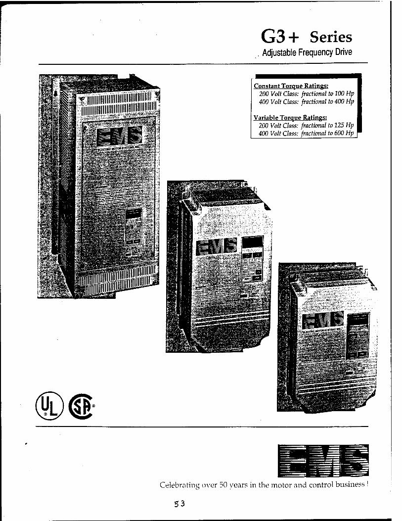
G3+ Series Adjustable Frequency Drive
Constant Torque Ratings: 200 Volt Class: fractional to 100 Hp 400 Volt Class: fractional to 400 Hp
Variable Torque Ratings: 200 Volt Class: fractional to 125 Hp 400 Volt Class: fractional to 600 Hp
Celebrating over 50 years in the motor and control business !
53
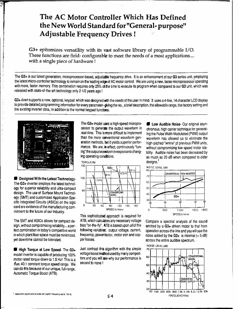
The AC Motor Controller Which Has Defined the New World Standard for "General- purpose" Adjustable Frequency Drives!
G3+ epitomizes versatility with its vast software library of programmable I/O. These functions are field- configurable to meet the needs of a most applications.... with a single piece of hardware!
The G3+ is our latest generation, microprocessor-based, adjustable frequency drive. It is an enhancement of our G3 series unit, employing the latest microcontroller technology to remain on the leading edgeof AC motor control. We are using a new, faster microprocessor operating with more, faster memory. This combination requires only 25% of {he time to execute its program when compared to our G3 unit, which was released with state-of-the-art technology only 2-1/2 years ago!
G3+ even supports a new, optional, keypad which was designed with the needs of the user in mind. It uses a 4-line, 14 character LCD display to provide detailed programming information for every parameter-giving the no., a brief description, the allowable range, the factory setting and the existing inverter data, in addition to the normal keypad functions.
■ Designed With the Latest Technology- The G3+ inverter employs the latest technol- ogy for superior reliability and ultra-compact design. The use of Surface Mount Technol- ogy (SMT) and customized Application Spe- cific Integrated Circuits (ASICs) on the logic card are evidence of the manufacturing com- mitment to the future of our industry.
The SMT and ASICs allows for compact de- sign, without compromising reliability... a per- fect combination in today's competitive world in which plant floor space must be minimized, yet downtime cannot be tolerated.
■ High Torque at Low Speed- The G3+ model inverter is capable of producing 100% motor rated torque down to 1.5 Hz! This is a the, 40:1 constant torque speed range. We can do this because of our unique, full-range, Automatic Torque Boost (ATB).
1 noise data applies onty to units with earner frequency set to 15 kHz
The G3+ model uses a high speed micropro- cessor to generate the output waveform in real-time. This is more difficult to implement than the more conventional waveform gen- eration methods, hut it yields superior perfor- mance. We are,« effect, continuously "tun- ing" the output waveform in response to chang- ing operating conditions.
TORQUE (%) 150
100
50
0 30 60 90 120 150 180 SPEED(r/min)
This sophisticated approach is required for ATB, which calculates any necessary voltage bias "on-the-fly". ATB is based upon a//of the following variables: output voltage, current, frequency, powerfactor, motor iron and cop- per losses.
Just contrast this algorithm with the simple voltage boost method used by many competi- tors and you will see why our performance is second to none I
i Q3 v\ \6Hz
\ UHz \ 4 5 Hz \
y 1.5Hz [ \ \
lHz\ v \ A \ \ \ 1
\ \ l \ \ C0NVENT10NÄ
1 iMODEL L \
\L. - \l| \ |i
■ Low Audible Noise- Our original asyn- chronous, high carrier technique for generat- ing the Pulse Width Modulated (PWM) output waveform has allowed us to eliminate the high-pitched "whine" pi previous PWM units, without compromising low speed motor sta- bility. Audible noise has been decreased by as much as 20 dB when compared to older designs.* NOISE LEVEL (dB) 80
70
60
50
40
30
0 500 1000 1500 1800
SPEED(r/min)
Compare a spectral analysis of the sound emitted by a G3+ driven motor to that from operation across-the-line and you will see the noise added by the G3+ is minimal (< 5 dB) across the entire audible spectrum. NOISE LEVEL (dB) 70
1 'ONVENTIONAL PWM INVERTER
G3+ 1
r t '
54 50 100 200 400 800 1.6k 3.15k 6.3k 12.5k 20k
FREQUENCY(Hz)

ED Using IGBTs- All of the G3+ models use the Insulated Gate Bipolar Transistor (IGBT) in their output section. This device has revo- lutionized the PWM inverter by facilitating higher switching frequencies. Further, it re- quires less componentry in its control cir- cuitry.
This device has many advantages over its predecessor, the bipolar transistor. Some of these are:
* switching times equal to 10 % of the bipolar 'direct drive from the logic circuitry, eliminat-
ing the need for layer upon layer of base drive current amplification.
* a wider safe operating area for greater operating margin/ reliability.
The higher switching frequency of the IGBT also results in a smoother, more efficient motor current waveform.
3 Password Protected- two separate lev- els of password protection can be used to protect programmed data from tampering.
3 Critical Frequency Rejection Points- up to four independently programmable points can be assigned to protect the driven equip- ment from continuous operation at harmful resonance frequencies.
O Electronic Motor Thermal Overload Protection- allows you to program the motor's FLA and shape of the trip curve. A specific fault code is issued if this protective function is activated.
O Fault History Function- the 4 most re- cent fault codes are stored in the inverter's non-volatile memory- for review even after the input power is cycled off and on.
3 Overtorque Detection- a programmable,
"shear-pin" used to annunciate a condition in which the motor current has exceeded a pro- grammed threshold for a time exceeding a programmed window. The G3+ can provide a host of responses in reaction to an overtorque- ranging from annunciation only to a fault trip.
£J Running Current Limit- if the output cur-
rent exceeds a user-defined level, the output voltage and frequency will automatically de- creasetogether. maintaining full motortorque, while preventing a nuisance fault trip.
3 Accel Current Limit- used to prevent nuisance inverter trips due to rapid accelera- tion. The G3+ will automatically extend the programmed accel ramp to limit the accel current.
3 2-wire or 3-wire Start/ Stop Control
3 Preset Speeds- up to 8 preset speeds
can be selected (plus jog speed).
3 Preset V/F Patterns-15 factory preset
patterns are available to choose from. In ad- dition, it is possible to customize a pattern to match the needs of highly specialized motors or applications.
S Accel/ Decel Ramps- two sets are inde-
pendently adjustable. Each is settable from
0.1 to 6000 sees.
£3 S-curve- you can select from any of three available times to smooth the accel/ decel of the driven machinery.
d AnalogMonitor-adigitallyscalable.multi-
function output is available for master slave configurations, remote metering, etc. This output can be configured for frequency or load indication.
(S DC Injection Braking
3 Automatic Fault Reset- field program-
mable no. of "intelligent" automatic fault re- sets. They are intelligent because a compo- nent failure will prohibit any reset attempts. preventing the possibility of further damage.
3 Coast Stop or Ramp Stop
3 Frequency Reference Loss Protection- if the analog reference input signal decreases dramatically, the inverter can automatically default to 80% of the last valid frequency.
£3 Speed Search- an algorithm used to start into a spinning motor without a nuisance fauit trip and without interrupting the motor's op- eration by first braking it to zero speed.
31 Inverted Master Frequency Reference- the characteristic of output frequency vs. ref- erence command can be inverted. This al- lows an increasing reference to result in a decreasing output frequency.

Appendix C
56
If * CM150TF-12H
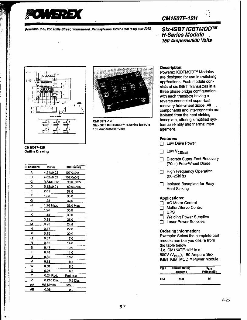
Powerex, Inc., 200 Mills Street, Youngwood, Pennsylvania 15697-1800 (412) 925-7272 Six-IGBTIGBTMOD™ H-Series Module , 150 Amperes/600 Volts
CM150TF-12H Outline Drawing
Dimensions Inches Millimeters
A 4.21 ±0.02 107.0*0.5 B 4.02±0.02 102.0±0.5 C 3.543*0.01 90.0*0.25 D 3.15±0.01 80.0*0.25 E 2.01 51.0 F 1.38 35.0 G 1.28 32.5 H 1.26 Max. 32.0 Max J 1.20 30.5 K 1.18 30.0 L 0.98 25.0 M 0.96 24.5 N 0.87 22.0 P 0.79 20.0 Q 0.67 17.0 R 0.55 14.0 S 0.47 12.0 T 0.43 11.0 U 0.39 10.0 V 0.33 8.5 w 0.31 8.0 X 0.24 6.0 Y 0.24 Rad. Rad. 6.0 z 0.216 Dia. 5.5 Dia.
AA M5 Metric M5 AB 0.08 2.0
CM150TF-12H Six-IGBT IGBTMOD™ H-Series Module 150 Amperes/600 Volts
Description: Powerex IGBTMOD™ Modules are designed for use in switching applications. Each module con- sists of six IGBT Transistors in a three phase bridge configuration, with each transistor having a reverse-connected super-fast recovery free-wheel diode. All . components and interconnects are isolated from the heat sinking baseplate, offering simplified sys- tem assembly and thermal man- agement.
Features: □ Low Drive Power
□ LowVCE(sat)
□ Discrete Super-Fast Recovery (70ns) Free-Wheel Diode
□ High Frequency Operation (20-25kHz)
□ Isolated Baseplate for Easy Heat Sinking
Applications: □ AC Motor Control □ Motion/Servo Control □ UPS □ Welding Power Supplies □ Laser Power Supplies
Ordering Information: Example: Select the complete part module number you desire from the table below -i.e. CM150TF-12Hisa 600V (VCES), 150 Ampere Six- IGBT IGBTMOD™ Power Module.
Type Current Rating Amperes
VCES VoltsTxSO)
CM 150 12
P-25
57
*[ *
Powerex, Inc., 200 Mills Street, Youngwood, Pennsylvania 15697-1800 (412) 925-7272
CM150TF-12H SMGBTIGBTMOD™ HSeries Module 150 Amperes/600 Volts
Resistive
Load
Switch Times
Tum-on Delay Time
Rise Time ^(0 200
Turn-off Delay Time
Fall Time 'd(off)
VCC = 300V, lc = 150A,
VGE1=VGE2=15V.RG = 4-2n
550 300
Diode Reverse Recovery Time
Diode Reverse Recovery Charge
300 lE = 150A, diE/dt = -300A/AIS 110 lE = 150A, diE/dt = -300A//1S 0.41
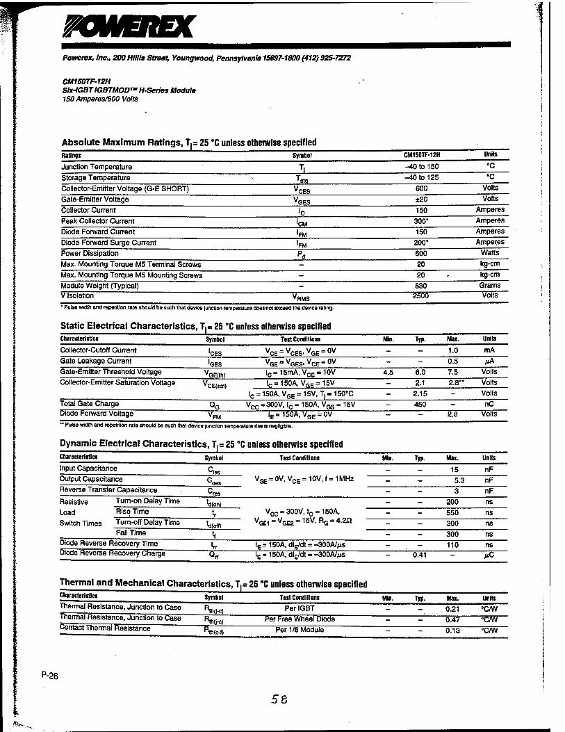
Absolute Maximum Ratings, T(= 25 °C unless otherwise specified Ratings Symbol CM1S0TF-12H Units
Junction Temperature Tl -40 to 150 °C Storage Temperature TStQ -40 to 125 •c Collector-Emitter Voltage (G-E SHORT) VCES 600 Volts
Gate-Emitter Voltage VGES ±20 Volts
Collector Current 'c 150 Amperes
Peak Collector Current 'CM 300* Amperes
Diode Forward Current 'FM 150 Amperes
Diode Forward Surge Current 'FM 200* Amperes
Power Dissipation Pd 600 Watts
Max. Mounting Torque M5 Terminal Screws - 20 kg-cm
Max. Mounting Torque M5 Mounting Screws - 20 • kg-cm
Module Weight (Typical) - 830 Grams
V Isolation VRMS 2500 Volts
' Pulse width and repetition rate should be such that device junction temperature does not exceed the device rating.
Static Electrical Characteristics, T(= 25 "C unless otherwise specified Characteristics Symbol Test Conditions Min. Typ. Max. Units
Collector-Cutoff Current 'CES vCE = vCES,vGE=ov - - 1.0 mA
Gate Leakage Current 'GES VGE = VGES.VCE = 0V - - 0.5 MA
Gate-Emitter Threshold Voltage VGE(th) lc= 15mA, VCE= 10V 4.5 6.0 7.5 Volts
Collector-Emitter Saturation Voltage VCE(sat) lf. = 150A, VRF = 15V - 2.1 2.8** Volts
lc = 150A, VGE = 15V, T, = 150°C - 2.15 - Volts
Total Gate Charge QG Vcc = 300V, lc = 150A, VGS = 15V - 450 - nC Diode Forward Voltage VFM
lE=150A, VGE = 0V - - 2.8 Volts
"Pulse width and repetition rate should be such that device junction temperature rise e negligible.
Dynamic Electrical Characteristics, T,= 25 °C unless otherwise specified Characteristics Symbol Test Conditions Min. Typ. Max. Units
Input Capacitance Cies VQE = 0V, VCE = 10V, f = 1MHz
- - 15 nF Output Capacitance Coes
Cres
- - 5.3 nF Reverse Transfer Capacitance - - 3 nF
ns
ns
ns
ns ns MC
Thermal and Mechanical Characteristics, T.= 25 "C unless otherwise specified Characteristics
Thermal Resistance, Junction to Case
Thermal Resistance, Junction to Case
Symbol
Contact Thermal Resistance
^q i-c) JWc) ^(c-l)
Test Conditions Min.
Per IGBT
Typ.
Per Free Wheel Diode
Per 1/6 Module
Max.
0.21 0.47
0.13
Unite
"C/W
"C/W
°C/W
P-26
58

Powerex, Inc., 200 Mills Street, Youngwood, Pennsylvania 1S697-1B00 (412) 925-7272
CM1S0TF-12H Slx-IGBT IGBTMOD™ HSerles Module 150 Amperes/600 Volts
OUTPUT CHARACTERISTICS (TYPICAL)
300
(0 UJ ?S0 IU
* vm J>
>F tr 150
ä 1 100 5
I 50
■T- 25°C-J* I I \A
15
ii
10
9
7 -4— R
— ' -■ I
0 2 4 6 8 10 COLLECTOR-EMITTER VOLTAGE, V&, (VOLTS)
COLLECTOR-EMITTER SATURATION VOLTAGE CHARACTERISTICS
(TYPICAL)
10
I8
|t a>° 6 a ui-
I 2
— T I™
■ * 25'C
lc = 30( )A
~- -le-i! IOA
L V V ̂ - I0 = 60A -
1 1 4 8 12 16 20
GATE-EMITTER VOLTAGE. VQE. (VOLTS)
HALF-BRIDGE SWITCHING CHARACTERISTICS
(TYPICAL)
103
O 102
101
— i ro
SC ^■a MB mm t —if «M »« I — <d
- 4 *'
t " in V / ■vcc-aoovr
VGE = ±15vf' / / Ti = i; 5'C
! if 101 102 103
COLLECTOR CURRENT. I,;, (AMPERES)
TRANSFER CHARACTERISTICS (TYPICAL)
300
250
200
150
100
50
1 1 1 1 vct= 1UV —T|=a*c — T| = 125*C
It
II II l II
/J
4 8 12 16 GATE-EMITTER VOLTAGE. VGE. (VOLTS)
FREE-WHEEL DIODE FORWARD CHARACTERISTICS
(TYPICAL)
20
103
tu |
i 102
101
T» = 25°C:
0 0.8 1.6 2.4 3.2 4.0 EMITTER-COLLECTOR VOLTAGE. VEC, (VOLTS)
REVERSE RECOVERY CHARACTERISTICS (TYPICAL)
103
102
101
'rr
[ I
oVdt = - J0C A/pse c
l|- Ü5" I
101
COLLECTOR-EMITTER SATURATION VOLTAGE CHARACTERISTICS
(TYPICAL)
3 4
5 >
p <
I I I I — Ti=r25*C
-•
.■•*■
-'£ ^l*'
*<& £'
50 100 150 200 250 COLLECTOR-CURRENT. !<;, (AMPERES)
CAPACITANCE VS. VCE (TYPICAL)
300
102
101
5 ioo
10-1
—[-- t 1 Mil
ct »
'1 r
vGE=ov 1 1 = 1MHz
I I 1 10-1 10» 101 102
COLLECTOR-EMITTER VOLTAGE. VCE. (VOLTS)
102 20 CO Ul
I o 16
GATE CHARGE, VQE
S £12
° 5 a: > uj cr a > UJ °
II ȣ 4
ioo 101 102
EMITTER CURRENT. IE, (AMPERES)
VC :" 2001 It
Vce = 3 oov
/ f
) / 1
103 100 200 300 400 500 600 GATE CHARGE. 00. (nO
P-27
59
P-28
Powerex, Inc., 200 Mills Street, Youngwood, Pennsylvania 15697-1800 (412) 925-7272
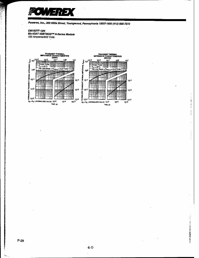
CM150TF-12H SIx-IGBTIGBTMOD^HSerles Module 150 Amperes/600 Volts
110,iQ2 101
„ TRANSIENT THERMAL IMPEDANCE CHARACTERISTICS
(K3BT) 10-1 100 ini
TRANSIENT THERMAL IMPEDANCE CHARACTERISTICS
(DIODE) ,10-3 1Q-2 10-1 100 1Q1
10-3 g 10-3 ^.^„.(NomuuzeDVALUE) 10* 10-4 10-3 ^.^.(NORUAUZEDVALUEI 10-5 10-* 10"3
TWE.(t) T1ME.(»)
10-3
60
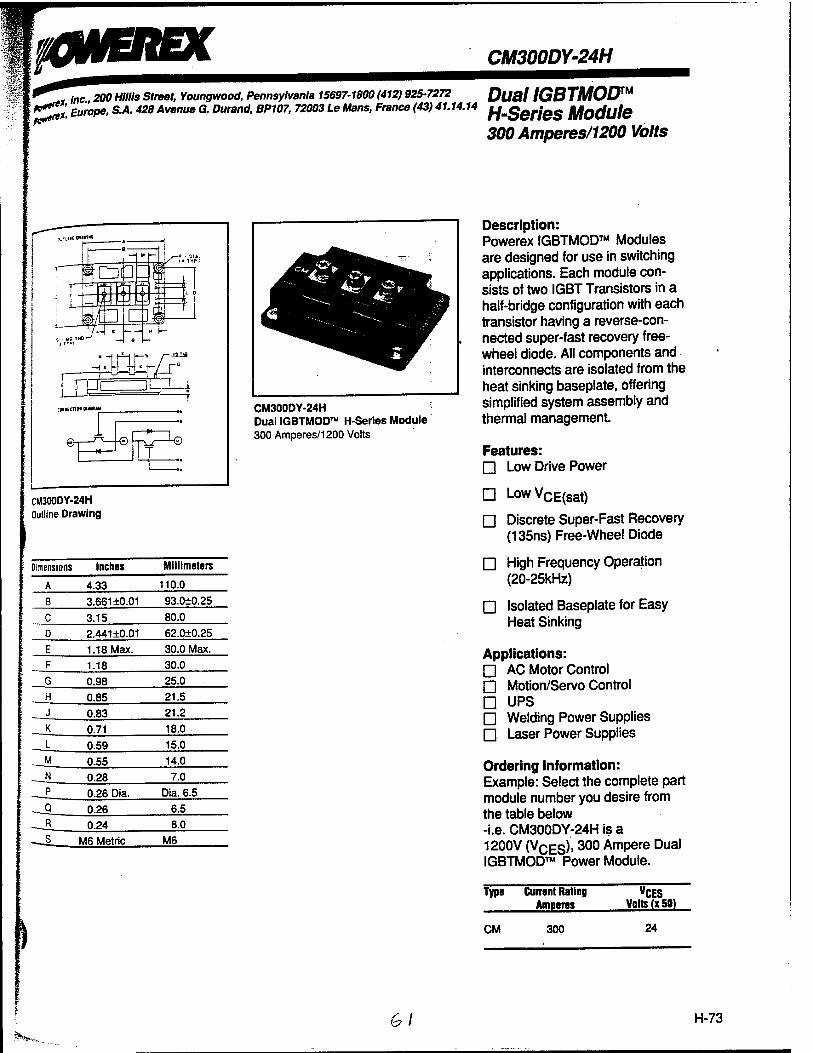
0H/EREX CM300DY-24H
^ tlnc 200 Hills Street, Youngwood, Pennsylvania 15697-1800 (412) 925-7272 DUSA IGBTMOD*** **%x, Europe, S.A. 428 Avenue G. Durand, BP107, 72003 Le Mans, France (43) 41.14.14 fJm§QrJQS Module
300 Amperes/1200 Volts
-w mm
CM300DY-24H Dual IGBTMOD™ H-Series Module 300 Amperes/1200 Volts
CM300DY-24H Outline Drawing
Dimensions Inches Millimeters
4.33 110.0 3.66110.01 93.010.25
3.15 80.0 2.44110.01 62.010.25 1.18 Max. 30.0 Max. 1.18 30.0 0.98 25.0 0.85 21.5 0.83 21.2 0.71 18.0 0.59 15.0
0.55 14.0 0.28 7.0 0.26 Dia. Dia. 6.5 0.26 6.5 0.24 6.0
M6 Metric M6
Description: Powerex IGBTMOD™ Modules are designed for use in switching applications. Each module con- sists of two IGBT Transistors in a half-bridge configuration with each transistor having a reverse-con- nected super-fast recovery free- wheel diode. All components and interconnects are isolated from the heat sinking baseplate, offering simplified system assembly and thermal management.
Features: □ Low Drive Power
□ LowVCE(sat)
□ Discrete Super-Fast Recovery (135ns) Free-Wheel Diode
□ High Frequency Operation (20-25kHz)
□ Isolated Baseplate for Easy Heat Sinking
Applications: □ AC Motor Control □ Motion/Servo Control □ UPS □ Welding Power Supplies □ Laser Power Supplies
Ordering Information: Example: Select the complete part module number you desire from the table below -i.e. CM300DY-24H is a 1200V (VCES), 300 Ampere Dual IGBTMOD™ Power Module.
Type Current Rating Amperes
VCES Volts (K 50)
CM 300 24
.**»» Gl H-73
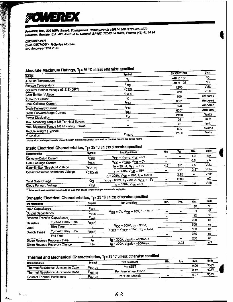
mNERBC powerex, Inc., 200 Mills Street, Youngwood, Pennsylvania 15697-1800 (412) S2S-7272 )>owerex, Europe, S.A. 428 Avenue G. Durand, BP107, 72003 Le Mans, France (43) 41.1.4.14
CM300DY-24H Dual IGBTMOD™ H-Serles Module
300 Amperes/1200 Volts
i
Absolute Maximum Ratings, T,= 25 °C unless otherwise specified
Ratings
Junction Temperature
Symbol
Storage Temperature
Collector-Emitter Voltage (G-E SHORT)
Gate-Emitter Voltage
Collector Current
Islg. VCES VGES
Peak Collector Current
Diode Forward Current
'CM
JEM_
Diode Forward Surge Current [FM
Power Dissipation
Max. Mounting Torque M6 Terminal Screws
Max. Mounting Torque M6 Mounting Screws
Module Weight (Typical)
V Isolation VRMS
• Pulse width and repetition rate should be such that device junction temperature does not exceed the device rating.
Static Electrical Characteristics, Tj= 25 °C unless otherwise specified
Characteristics Symbol Test Conditions
Collector-Cutoff Current 'CES Vpp-Vr.FR.Vf^OV
Gate Leakage Current JQES_ Gate-Emitter Threshold Voltage vGE(tm
Collector-Emitter Saturation Voltage vCE(sat)
lr, = 30mA, VCE= 10V lr. = 300A,VfiE = 15V
CM300DY-24H
-40 to 150
-40 to 125
Min.
4.5
ln . 300A, VGF = 15V, T| = 150°C
Total Gate Charge _QQ_ Diode Forward Voltage VFM
ycn = 600V, \r. = 300A, VQS = 15V lE = 300A, VQS • 0V
" Pulse width and repetition rate should be such that device junction temperature rise is negligible.
Dynamic Electrical Characteristics, Tj=25 °C unless otherwise specified
Chars et» rl sties Test Conditions Min.
Input Capacitance ^ies
Output Capacitance ±oes_ VGE = 0V, VCE = 10V, f = 1 MHz
Turn-on Delay Time
Reverse Transfer Capacitance
Resistive
Load
Switch Times
■'res
^(on)
Rise Time
Turn-off Delay Time Jdiflffl-
vcc = 600V> 'c = 300A- VGE1=VGE2 = 15V,RG = 1.0Q
Fall Time
Diode Reverse Recovery Time Diode Reverse Recovery Charge
lF = 300A, dip/dt = -600A/;ns lE = 300A, diF/dt = -600A/MS
1200
±20
300
600*
300
600* 2100
26 26 500
2500
Typ.
6.0 2.5
2.25
1500
Typ.
2.23
Max.
1.0
0.5
7.5
3.2*
3.4
Mas.
60
21
12
250
500
350
350 250
Units
Volts
Volts
Amperes
Amperes
Amperes
Amperes
Watts
in-lb
in-lb
Grams
Volts
Units
mA I MA
Volts
Volts
Volts
nC
Volts
Units
nF
nF
nF
ns
ns
ns
ns
»C
Thermal and Mechanical Characteristics, Tl= 25 °C unless otherwise specified
Characteristics
Thermal Resistance, Junction to Case
Symbol
^th(j-c)
Thermal Resistance, Junction to Case Rth(i-c)
Contact Thermal Resistance Rthfc-n
Test Conditions
Per IGBT
Per Free Wheel Diode
Per Half Module
Min. Typ. Mas.
0.06
0.12 0.07
Units
°c/w °c/w °c/w 4
i
6&

&&MX *"" 0X me, 200 Hlllis Street, Youngwood, Pennsylvania 15697-1800 (412) 925-7272 \°*Lrex, Europe, S.A. 428 Avenue G. Durand, BP107, 72003 Le Mans, France (43) 41.14.14
10OOOY-2M
%Amperes/1200 Volts HGBTMOD"* H-Series Module
OUTPUT CHARACTERISTICS (TYPICAL)
SO
iBO
360
240
-? J
ov 1 r1S s 12
i I It
T - J5°C II 11 ■J
I
i 10
" i WS 9
7 - ; fr i /
0 2 4 6 8 10 COLLECTOR-EMITTER VOLTAGE. VCE. (VOLTS)
COLLECTOR-EMITTER SATURATION VOLTAGE CHARACTERISTICS
(TYPICAL)
10 i
j
; 8 'C" 600A
- * j • 6
"~~> ■ lC - 300A
, *
* -^ ̂
•Sa
; 2 lc - 120A
!
0 4 8 12 16 20 GATE-EMITTER VOLTAGE. VQJ. (VOLTS)
HALF-BRIDGE SWITCHING CHARACTERISTICS
(TYPICAL)
TRANSFER CHARACTERISTICS (TYPICAL)
600
S 480
360
240
120
I V,— ,
i — Tj = 25°C —- ij-
I
n it
il
4 8 12 16 GATE-EMITTER VOLTAGE. VQJ. (VOLTS)
FREE-WHEEL DIODE FORWARD CHARACTERISTICS
(TYPICAL)
20
103
S 102
101
1 1
1. - 25°C :
^
i
0 0.8 1.6 2.4 3.2 4.0 EMrTTER-COLLECTOR VOLTAGE. VEC. (VOLTS)
REVERSE RECOVERY CHARACTERISTICS (TYPICAL)
103
102
101
i—,— rH L_ I
«rr
di/d r- ior A Tr 25° c
102
101
COLLECTOR CURRENT, lc. (AMPERES)
101 l02
EMITTER CURRENT. IE. (AMPERES)
103
COLLECTOR-EMITTER SATURATION VOLTAGE CHARACTERISTICS
(TYPICAL)
$ 4
UJ O
i-
I
i r ; i:i i ■ : i i
Tr25X j | ! j |
I ! _ III! | i
**&*' i <£* *' ;
>'
/ w*'
i i 120 240 360 480
COLLECTOR-CURRENT. Ic. (AMPERES)
CAPACITANCE VS. VCE (TYPICAL)
600
102
u. 101
| 10°
s
10-1
■ ! injiii i^=zz -A—i 11;, n ill 1 "ies iT*Tt
II NVll! i
|| ^*L i . wl -r-|-i-t Lc
!l \ ; ■ i
t! \ " i 1 i 1 Cres
—i—j- ; ! •:
_41 ■ * ■•■ l—-j r*
I vßE-o\ / I. 1» »Hi
1 jii il 1 | III 10-1 10° 101 102
COLLECTOR-EMITTER VOLTAGE. VCE. (VOLTS)
GATE CHARGE, VQE
20
Ig16
i) tu IU -ig EC M '*
ui c 8 > Ui ° 8 E S 2
10"
-lC- I I ^
\ff V<^-<IMN Jjf
//v<x = 600V
/* /
i f
/ —
600 1200 1800 2400 GATE CHARGE. 0G. (nCI
:-^, 63 H-75

ooverex, Inc., 200 Mills Street, Youngwood, Pennsylvania 15697-1800(412) S25-7272 powerex, Europe, S.A. 428 Avenue G. Durand, BP107, 72003 Le Mans, France (43) 41.14.14
CM300DY-24H pual IGBTMOD"1 H-Series Module 300 Amperes/1200 Volts
TRANSIENT THERMAL IMPEDANCE CHARACTERISTICS
(IGBT) ■10-3 1Q-2 10-1 10° 101
I 101
TRANSIENT THERMAL IMPEDANCE CHARACTERISTICS
(DIODE) ,10-3 1Q-2 1Q-1 1Q0 1Q1
10-1 | 10-i
10-2 C 10-2 o uj
I ^ m 10-3 | 10-3
,R„-(NORMALIZED VALUE) 10"5 10"4 10"3 ^ , „ffi . {NORMALIZED VALUE) 10"5 10"4 10" TIM6. (s)
10-3
i
I
,SK <^4

Appendix D
6£~
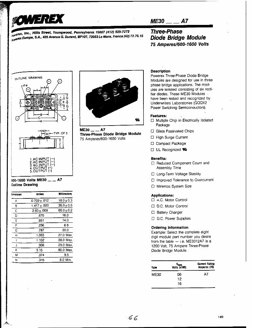
awaiEX *^ex, Inc., H/H/s Street, Young wood, Pennsylvania 15697 (412) 925-7272 ^re*Europe, S.A., 428 Avenue G. Durand, BP107,72003 Le Mans, France (43) 72.75.15
ME30 A7
Three-Phase Diode Bridge Module 75 Amperes/600-1600 Volts
OUTLINE DRAWING
-F<*
efawä^ pJM[— TYP. OF 3
"T
1. AC INPUT I- 2 AC INPUT - 3.AC INPUT (- 4.0UTPUT(+) 5. OUTPUT (-)
600-1600 Volts ME30 Outline Drawing
_A7
Dimension Inches Millimeters
A 0.709+ .012 18.0 ±0.3
B 1.417+ .020 36.0 ±0.5
C 2.60 ±.008 66.0 ±0.2
D .670 16.0
E .551 14.0
F .256 6.5
G .787 20.0
H 1.063 27.0 Max.
I 1.102 28.0 Max.
J .906 23.0 Max.
K 3.15 80.0 Max.
M .374 9.5
N .315 8.0 Min.
ME30 A7 Three-Phase Diode Bridge Module 75 Amperes/600-1600 Volts
Description Powerex Three-Phase Diode Bridge Modules are designed for use in three phase bridge applications. The mod- ules are isolated consisting of six recti- fier diodes. These ME30 Modules have been tested and recognized by Underwriters Laboratories (QQQX2 Power Switching Semiconductors).
Features: D Multiple Chip in Electrically Isolated
Package
D Glass Passivated Chips
D High Surge Current
D Compact Package
D UL Recognized TO
Benefits: D Reduced Component Count and
Assembly Time
D Long-Term Voltage Stability
D Improved Tolerance to Overcurrent
D Minimize System Size
Applications: D A.C. Motor Control
D D.C. Motor Control
□ Battery Charger
D D.C. Power Supplies
Ordering Information Example: Select the complete eight digit module part number you desire from the table — i.e. ME3012A7 is a 1200 Volt, 75 Ampere Three-Phase Diode Bridge Module.
Type
ME30
VoltsTlOO)
06 12 16
Current Rating Amperes (75)
A7
.A <£"^ 149
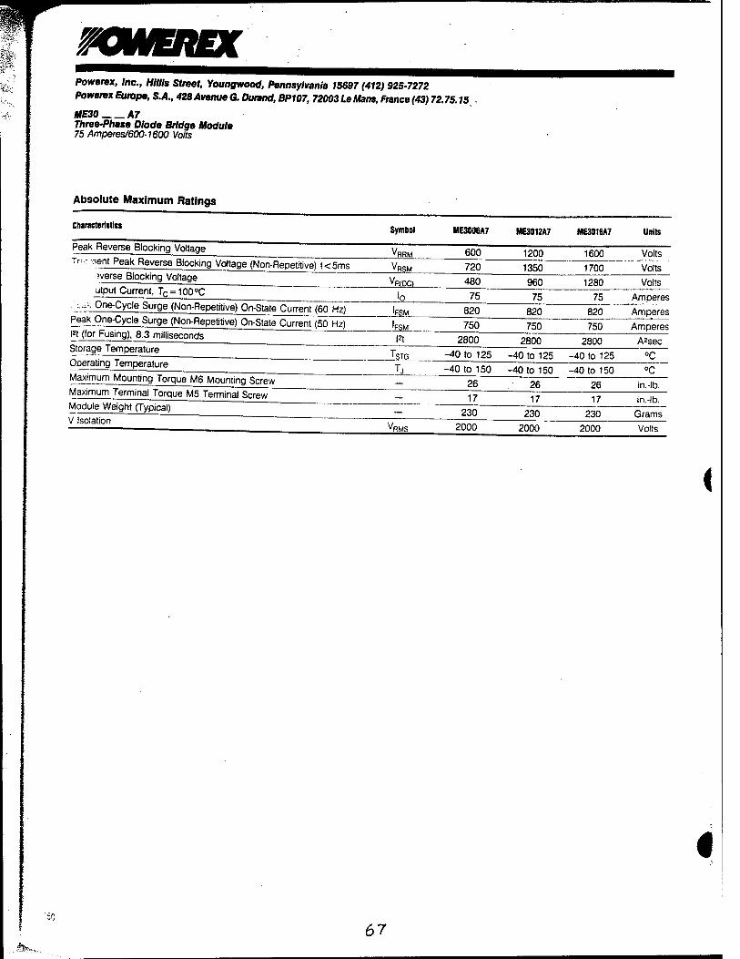
mWEREX Powerex, Inc., Mills Street, Youngwood, Pennsylvania 15697 (412) 925-7272
PowerexEurope, S.A., 428Avenue G. Durand, BP107, 72003LeMans, France (43) 72.75.IS
ME30 A7 Three-Phase Diode Bridge Module 75 Amperes/600-1600 Volts
Absolute Maximum Ratings
Characteristics
Peak Reverse Blocking Voltage
Tr^-ient Peak Reverse Blocking Voltage (Non-Repetitive) t<5ms
vverse Blocking Voltage
utput Current, Tc =100°C
.^K One-Cycle Surge (Non-Repetitive) On-State Current (60 Hzj~
Peak One-Cycle Surge (Non-Repetitive) On-State Current (50 Hz)
m (for Fusing), 8.3 milliseconds
Storage Temperature
Operating Temperature
Maximum Mounting Torque M6 Mounting Screw
Maximum Terminal Torque M5 Terminal Screw
Module Weight (Typical)
V Isolation
Symbol
VRRM
VRSM
VR(DC)
'FSM
'FSM
l*t
ME300EA7 ME3012A7 ME3016A7 Units
600 1200 1600 Volts
720 1350 1700 Volts
480 960 1280 Volts
75 75 75 Amperes
820 820 820 Amperes
750 750 2800
750 Amperes
2800 2800 A2sec
'STG -40 to 125 -40 to 125 -40 to 125
-40 to 150 -40 to 150 -40 to 150 °C 26 26 26 in.-lb.
17 17 17 230 230 230
in.-lb.
Grams VRMS 2000 2000 2000 Volts
<
'50
67
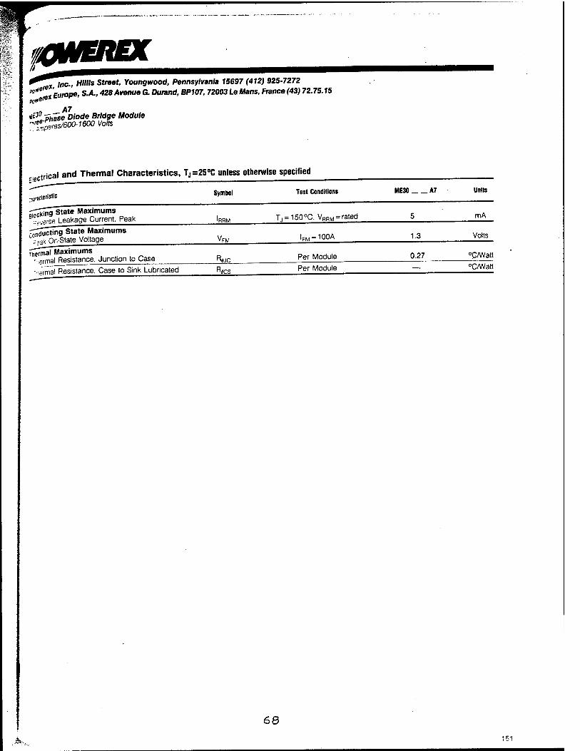
0WEREX - * ine- Hillis streot' Youngwood, Pennsylvania 15697 (412) 925-7272 ^^JEurope, S.A., 428AvenueG. Durand, BP107, 72003LeMans, France(43) 72.75.15
A7 tf3° ~5häse Diode Bridge Module '^fp"res/600-1600 Volts
trical and Thermal Characteristics, Tj=25°C unless otherwise specified
Symbol Test Conditions ME30 A7 Units
" ,ifina State Maximums . B'°g| Leakage Current. Peak ^ T.,-150°C. VRRM-rated 5 mA_
rr^ictina State Maximums _ „ w „ "gg" State Voltage V™ 'FM-100A li Volts_
^jjSSS. Junction to Case R^c_ Per Module 027 ^/Watt
-■^rm^lResistance. Case to Sink Lubricated B^s Per Module — °C/Watt
68
M>,_

mvEtwc Powerex, Inc., Mills Street, Youngwood, Pennsylvania 15697 (412) 925-7272
Powerex Europe, S.A., 428 Avenue G. Durand, BP107, 72003 Le Mans, France (43) 72.75.15
ME30 A7 Three-Phase Diode Bridge Module 75 Amperes/600-1600 Volts
MAXIMUM ON-STATE CHARACTERISTICS
o > ui
z o to
o
10° 10' 102 103
INSTANTANEOUS ON-STATE CURRENT. I.M. (AMPERES)
IT DC
O
ui _
II tu T S 2 X U]
U)
< UJ 0. 5 D 2 X < 2
MAXIMUM (NON-
1000
800
600
400
200
ALLOWABLE PEAK SURGE REPETITIVE) CURRENT
I i ! jj Tj=.25°C I I ! Ill \ I I i \j ! i
1
■ i i i ii j il i
r4 ü : ! 1 ■■ ;l ! i * 1
! | : i i 1 ■ 1
10° 10' CYCLES AT 60 Hz
O e
Kö 160
ui I 140 i- S 120 Hi
5 ioo
S 80
MAXIMUM ALLOWABLE CASE TEMPERATURE
< 3 o
UJ 60 ;•---
102 x 0 20 4u 60 80 100
DC OUTPUT CURRENT. IQ. (AMPERES)
MAXIMUM ON-STATE POWER DISSIPATION
.0 10 20 30 40 50 60 70 100 DC OUTPUT CURRENT. IQ. (AMPERES)
<
152
69
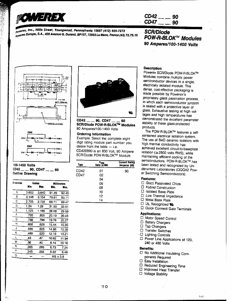
KWEIIEX CD42 90 CD47 90
„^eret, Inc., Mills Street, Young wood, Pennsylvania 15697 (412) 925-7272 SCR/DinHf* ^erexEurope, S.A., 428AvenueG. Durand, BP107, 72003LeMans, France(43) 72.75.15 onw D DirnsTM mm
90 Amperes/100-1400 Volts
y««HG mriTKn
CD42
Tf KM ! « »U, 0 TERM 2' H o TERM 3
' -O TERM 4
CD47
TERM 1 * W—»TERM 2 '
1 OTI
-^W OTI
100-1400 Volts CD42 90, CD47 90 Outline Drawing
Dimension Inches Min. Mix.
Millimeters Mln. Max.
3.602 3.640 91.49 92.45
3.146 3.154 79.91 80.11 2.705 2.735 68.71 69.47 1.24 1.28 31.50 32.51 1.125 1.165 28.58 29.59
.805 20.19 20.45 .795 _G_
_H_
_J_
_K_
_L_
-Ü _N_
P
Q
.788 .798 19.76 20.27
.608 .628 15.44 15.95
.585 .605 14.86 15.36
■480 .520 12.19 13.21 .43 .47 10.92 11.94 .36 .40 9.14 10.16 ■265 .285 6.73 7.24
6.48 .245 .255 6.22
— . M5 x 0.8
CD42 90, CD47 90 SCR/Diode POW-R-BLOK™ Modules 90 Amperes/100-1400 Volts
Ordering Information Example: Select the complete eight digit rating module part number you desire from the table — i.e. CD420890 is an 800 Volt, 90 Ampere SCR/Diode POW-R-BLOK™ Module.
Type Volts (x100) Current Rating Amperes (90)
CD42 01 CD47 02
04 06 08 10 12 14
90
Description Powerex SCR/Diode POW-R-BLOK™ Modules combine multiple power semiconductor devices in a single, electrically isolated module. This dense, cost-effective packaging is made possible by Powerex's proprietary glass passivation process, in which each semiconductor junction is sealed with a protective layer of glass. Exhaustive testing at high vol- tages and high temperatures has demonstrated the excellent parameter stability of these glass-protected products.
The POW-R-BLOK™ features a self- contained electrical isolation system. The use of BeO ceramic isolators with high thermal conductivity has achieved excellent circuit-to-baseplate isolation (>2500 volts RMS), while maintaining efficient cooling of the semiconductors. POW-R-BLOK™ has been tested and recognized by Un- derwriters Laboratories (QQQX2 Pow- er Switching Semiconductors).
Features: D Glacs Passivated Chips □ Hybrid Construction Ü Isolated Base Plate O Low Thermal Impedance Ü Metal Base Plate Ü UL Recognized «M Ü Quick Connect Gate Terminals
Applications: Ü Motor Speed Control D Battery Chargers D Tap Changers O Transfer Switches
■ D Lighting Controls D Power Line Applications of 120,
240 or 480 Volts
Benefits: Ü No Additional Insulating Com-
ponents Required D Easy Installation D Reduced Engineering Time Ü Improved Heat Transfer D Voltage Stability
10

WEREX Powerex, Inc., Mills Street, Youngwood, Pennsylvania 1S697 (412) 925-7272 Powerex Europe, S.A., 428 Avenue G. Durand, BP107,72003 Le Mans, France (43) 72.75.15
CD42 90, CD47 90 SCWDiode POW-R-BLOKm Modules 90 Amperes/100-1400 Volts
Absolute Maximum Ratings
Characteristics Symbol C0420190 CD470190
CD420290 CD470290
CD420490 CD470490
CD420690 CD470S90 Units
Peak Forward Blocking Voltage VDRM 100 200 400 600 Volts
Peak Reverse Blocking Voltage VRRM 100 200 400 600 Volts
Transient Peak Reverse Blocking Voltage (Non-Repetitive) t<5 ms
VRSM 200 300 500 700 Volts
Characteristics Symbol CD420890 C0470890
CD421090 C0471090
C0421290 C0471Z90
C0421490 C04714M Units
_-ak Forward Blocking Voltage VQRM 800 1000 1200 1400 Volts
sak Reverse Blocking Voltage VRRM 800 1000 1200 1400 Volts
Transient Peak Reverse Blocking Voitage (Non-Repetitive) t<5 ms VRSM 950 1200 1450 1700 Volts
<
< I 1
11
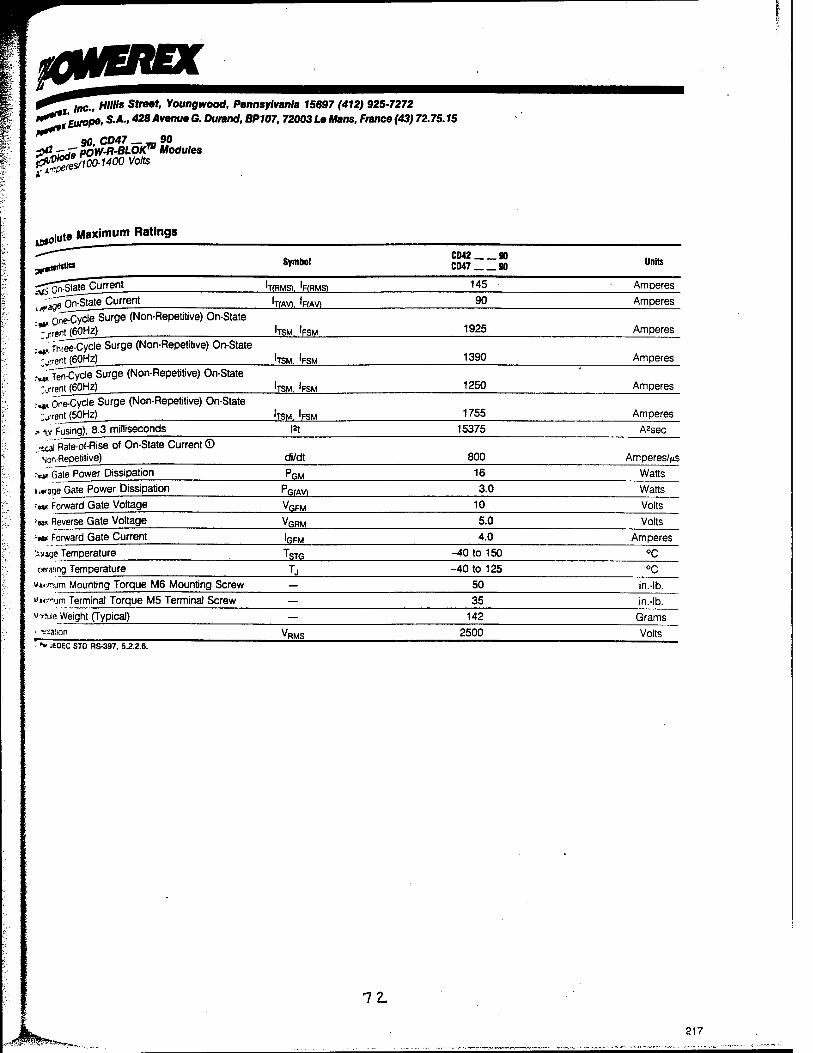
iC&EREX "^IflC., HIHis Street, Youngwood, Pennsylvania 75697 (412) 925-7272
"**"'Europe, S.A., 428 Avenue G. Durand, BP107,72003 Le Mans, France (43) 72.75.15
90, CD47 _ _ 90 P3^ POW-R-BLOK™ Modules l&^SoO-l400 Volts aperes.
,-fllute Maximum Ratings
^ftHtMM Symbol CD42 90 CD47 90 Units
-jpCstäte Current 'T(RMS). IpfRMS) 145 Amperes
"^Tn^Stete Current 'TfAvi. IRAVI 90 Amperes
One-Cycle Surge (Non-Repetitive) On-State
"?r,«nt /60Hz) 'TSM. 'FSM 1925 Amperes
. Three-Cycle Surge (Non-Repetitive) On-State
""„rent (60HZ) 'TSM. 'FSM 1390 Amperes
.-«^Ten-Cycle Surge (Non-Repetitive) On-State
' -.««nt (60Hz) 'TSM. 'FSM 1250 Amperes
i*t One-Cycle Surge (Non-Repetitive) On-State -.„■rent (50Hz) 'TSM. 'FSM 1755 Amperes
r flat Fusing), 8.3 milliseconds |2t 15375 A2sec
-xai Rate-of-Rise of On-State Current © son Repetitive) di/dt 800 Amperes/Vs
r«* Gate Power Dissipation PGM 16 Watts
i*aoe Gate Power Dissipation PG(AV) 3.0 Watts
■w. Forward Gate Voltage VGFM 10 Volts
?««Reverse Gate Voltage VGRM 5.0 Volts
*'»* Forward Gate Current IGFM 4.0 Amperes
'»age Temperature TSTG -40 to 150 °C c«a!ing Temperature L -40 to 125 °C
v*«mum Mounting Torque M6 Mounting Screw — 50 in.-lb.
wnfiurn Terminal Torque M5 Terminal Screw — 35 in.-lb.
Wuie Weight (Typical) — 142 Grams
• taaiion VRMS 2500 Volts
• JEDEC STD RS-397, S.2.2.6.
72.
217
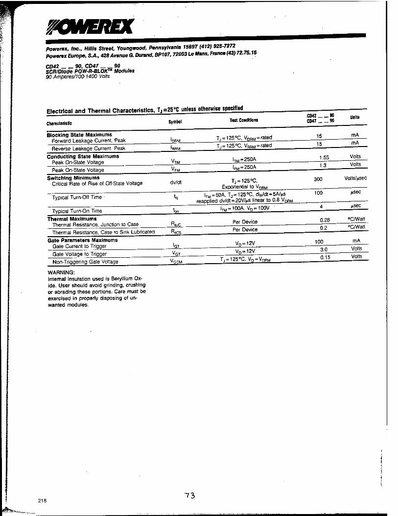
mWEREX Powerex, Inc., Mills Street, Youngwood, Pennsylvania 15697 (412) 925-7272 Powerex Europe, S.A., 428 Avenue G. Du rand, BP107, 72003 Le Mans, France (43) 72.75.15
CD42 90, CD47 90 SCR/Diode POW-R-BLOK™ Modules 90 Amperes/100-1400 Volts
Electrical and Thermal Characteristics, Tj=25°C unless otherwise specified
Ted Conditions Characteristic Symbol
CD« 90 Units
CD47 90
Blocking State Maximums Forward Leakage Current, Peak
Typical Turn-On Time
Thermal Maximums Thermal Resistance, Junction to Case
Thermal Resistance, Case to Sink Lubricated
Gate Parameters Maximums Gate Current to Trigger
Gate Voltage to Trigger
Non-Triggering Gate Voltage
WARNING: Internal insulation used is Beryllium Ox- ide. User should avoid grinding, crushing or abrading these portions. Care must be exercised in properly disposing of un- wanted modules.
'DRM
Reverse Leakage Current, Peak
Conducting State Maximums Peak On-State Voltage
Peak On-State Voltage
Switching Minimums Critical Rate of Rise of Off-State Voltage
Typical Turn-Off Time
"TM
dv/dt
ton
•^JC
•^flCS
'GT
•GT
"GDM
T,,-125°C. VDRM = rated
T, = 125°C, VRRM = rated
15 15
mA
mA
ITM~250A
FM = 250A
1.55 1.3
Volts
Volts
Tj = 125°C, Exponential to VDRM
300 Volts//isec
lTM = 50A, Tj = 125°C, diR/dt = 5A/^S 100 reapplied dv/dt = 20V/>ts linear to 0.8 VDRM
ITM = 100A, VD=100V
/isec
/isec
Per Device 0.28 "C/Watt
Per Device 0.2 °C/Watt
VQ=12V 100 mA
VQ-12V 3.0 Volts
T, = 125°C, VD = V, DRM 0.15 Volts
218 ~?^
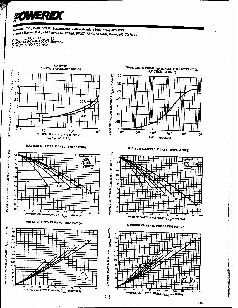
XWEREX poterex. Inc., Mills Street, Youngwood, Pennsylvania 15697 (412) 925-7272 po^rexEurope, S.A.,428AvenueG.Durand, BP107, 72003LeMans,France(43)72.75.15
rn42 90, CD47 90 ffl/ode POW-R-BLOKTU Modules ljAmperes/100-1400 Volts
MAXIMUM ON-STATE CHARACTERISTICS
; 4.0
\ 3.5
s 3.0 > i 2 5
I I
_i_ ....
I i
?0
1 s SCR +--J
1 0
ns J Diode I
0 1 I 10 o 101
102 m3 INSTANTANEOUS ON-STATE CURRENT
W W (AMPERES)
TRANSIENT THERMAL IMPEDANCE CHARACTERISTICS (JUNCTION TO CASE)
10'3 10-2 10"1
TIME, I, (SECONDS) 10° 101
MAXIMUM ALLOWABLE CASE TEMPERATURE MAXIMUM ALLOWABLE CASE TEMPERATURE
AVERAGE ON-STATE CURRENT, L^. (AMPERES)
MAXIMUM ON-STATE POWER DISSIPATION
AVERAGE ON-STATE CURRENT, l^. (AMPERES)
IT I!
<
< o
s 3 2 x < S
<
z o
a x m i O CL
s D 2
s
AVERAGE ON-STATE CURRENT, i^ (AMPERES)
MAXIMUM ON-STATE POWER DISSIPATION
'05 120
74 AVERAGE ON-STATE CURRENT, ^ (AMPERES)
219

maiEREx Powerex, Inc., Mills Street, Youngwood, Pennsylvania 15697 (412) 925-7272 Powerex Europe, S.A., 428 Avenue G. Durand, BP107,72003 Lallans, France (43) 72.75.15
CD42 90, CD47 90 SCO/Diode POW-R-BLOKm Modules 90 Amperes/100-1400 Volts
z o
a cr
§
s 2
<
a.
CO 5 i LU S o
I
z o p <
<o 5 <E LU
I -J
I s
MAXIMUM TOTAL POWER DISSIPATION AND MAXIMUM AMBIENT TEMPERATURES AC SWITCH
1 CD42 90orCD47 90
fc 250 — B7.5 3 C 3 > r- r- O s
m o
0 20 40 60 80 100 120 140 160 180 200 220 240 0 5 IS 25 35 45 55 65 75
lRMS, (AMPERES) T AMBIENT, (°C)
1*—BRIDGE RESISTIVE AND INDUCTIVE LOAD 2 CD42 90 or CD47 90
95 105 115 125
3 > x 3 c s
o s >
L"75 ffi
0 20 40 60 80 100 120 140 160 180 200 220 240 0 5 15 25 35 45 55 65 75
1^., (AMPERES) T AMBIENT, (°C)
34-BRIDGE AND AC SWITCH 3 CD42 .90 or CD47 90
95 105 115 125
3 > x 3 C 3
I > CO m
120 i.
220
°0 25 50 75 100 125 150 175 200 225 250 275 300 0 5 15 25 35 45 55 65 75 85 95 105 115 125
lRMS/lDC. (AMPERES) — T AMBIENT, (°C)
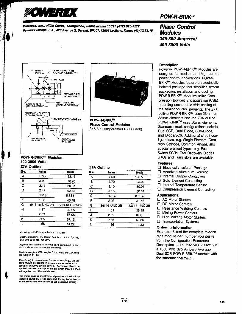
w
I
WWEREX POW-R-BRIK™ Powerex, Inc., Mills Street, Youngwood, Pennsylvania 15697 (412) 925-7272 powerex Europe, S.A., 428 Avenue G. Durand, BP107, 72003 Le Mans, France (43) 72.75.15
Phase Control Modules 345-800 Amperes/ 400-3000 Volts
I
• 0 TAPPED HOLE X SO DEEP TYP. 3 PUCES
- E 0 THRU HOLE TYP. 4 PLACES IFOR TYP. I/4-W SOCKET HD. SOU
14 BELLEVILLE 5FRI«0 WASHEA!
yB Al/W My | \ I» Al/W My I
^4^" \
n UARKIKG:KI ICATWODEJ. AtAZ IAN0DET/1CATM0EI. tA2(A*00ElAS5H0W«
-WARIflNQ: DEVICE AND DIRECTION ACCORDING TO CIRCUIT CONFIGURATION CHART
GATE [WHITEJ* CATHODE IREDI LEADS 12-5 IK. LONG WITH .375 IN. LCNG STRIPPED EHOS
-HARKING: STYLE BO. WITH
I £71,0005/1X1,
THIS SURFACE VUST BE PROTECTED AND ROT DAMAGED
POW-R-BRIK™ Modules 400-3000 Volts
Z7A Outline Dim. Inches Metric
A 6.30 153.16 B 3.02 76.70 C 3.15 80.01 D 2.47 62.73 E .328 + 8.33 + F 1.83 46.48 G 5/16-18 UNC-2B 5/16-18 UNC-2B H 1.27 32.25 J 2.09 53.08 K 2.25 57.15 L .56 14.22
Mourning bolt (E) torque limit is 11 ft./lbs.
Electrical terminal (G) torque limit is 11 ft. lbs. for type Z7A and 20 ft. lbs. for Z9A.
Apply a thin coating of thermal joint compound to heat sink surface prior to module mounting.
Module weights: Z7A weighs 6 lbs. while the 29A mod- ule weighs 11 lbs.
If incoming tests are done for isolation voftage, the vol- tage should be applied in a slow manner rather than abruptly imposed on the device. The voltage should be applied between the top terminals, which must be short- ed together, and the metal case.
The metal case is anodized and provides added voltage isolation capability if not damaged: factory hi-pot test is achieved without the benefit of the anodized coating.
POW-R-BRIK™ Phase Control Modules 345-800 Amperes/400-3000 Volts
Z9A Outline Dim. Inches Metric
A 7.50 190.5 B 3.70 93.98 C 3.15 80.01 D 3.15 80.01 E .328 + 8.33 + F 2.03 51.56 G 3/8-16 UNC-2B 3/8-16 UNC-2B H 1.51 38.35 J 2.52 64.0 K 2.75 69.85 L .56 14.22
Description Powerex POW-R-BRIK™ Modules are designed for medium and high current power control applications. POW-R- BRIK™ Modules feature an electrically isolated package that simplifies system packaging, installation and cooling. POW-R-BRIK™ Modules utilize Com- pression Bonded Encapsulation (CBE) mounting and double side cooling of the semiconductor elements. The Z7A outline POW-R-BRIK™ uses 33mm or 38mm elements and the Z9A outline POW-R-BRIK™ uses 50mm elements. Standard circuit configurations include Dual SCR, Dual Diode, SCR/Diode, and Diode/SCR. Additional circuit con- figurations, e.g. Single Element, Com- mon Cathode, Common Anode, and special element types, e.g. Fast Switch SCRs, Fast Recovery Diodes GTOs and Transistors are available.
Features: D Electrically Isolated Package D Anodized Aluminum Housing D Internal Copper Contacting D Gold Element Contacting D Internal Temperature Sensor D Compression Element Contacting
Applications: D AC Motor Starters D DC Motor Controls D Resistance Welding Controls D Mining Power Centers D High Voltage Motor Starters D Transportation Systems
Ordering Information Example: Select the complete thirteen digit module part number you desire from the Configuration Reference Description — i.e. P3Z7ACT700W16 is a 1600 Volt, 375 Ampere Average, Dual SCR POW-R-BRIK™ module with the standard thermistor.
16 445
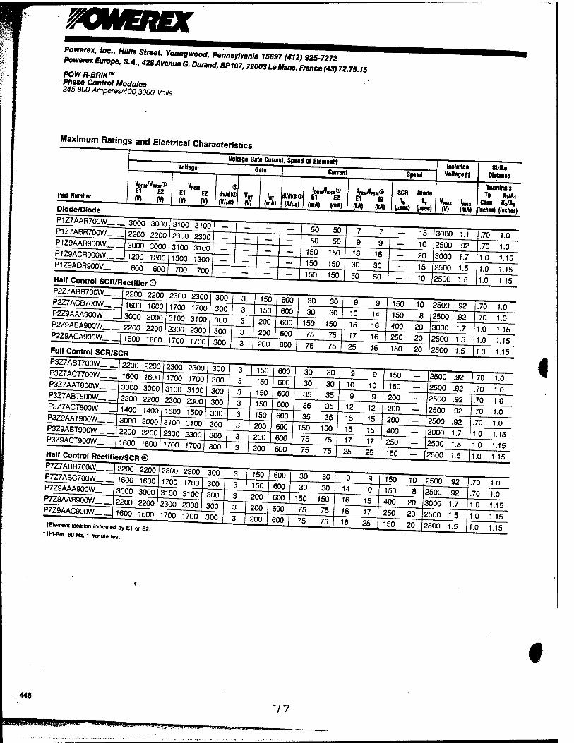
owEnn PoweretInc., Mills Street, Youngwoo*Pennsy^^97«^^ Povereteurope,S.A.,428AvenueG.Du„nd>^ 72003t^Z™)72.75,5
POtV-fl-BfW» Phase Control Modules 345-800 Amperes/400-3000 Volts
Maximum Ratings and Electrical Characteristics
4
tHement location indicated by E1 or E2. ttHI-Pot. 60 Hz, 1 minute test
446
"W-MjgJg^liyimjilBWW
"7 7

powerex, Inc., Mills Street, Youngwood, Pennsylvania 15697 (412) 925-7272 powerax Europe, S.A., 428 Avenue G. Dunmd, BP107, 72003 Le Mans, France (43) 72.75.75
POW-R-BRIIC" Phase Control Modules 345-800 Amperes/400-3000 Votts
- Current and Thermal Ratings of Module
* Circuit Currents
Element Data Model*
Current Thermal Units Per Sink-
T« (•C)
1 AC
Switch
W
3 AC
Switch® 'am (A)
2 1+
Bridge IDC (A)
3 3+
Bridge® >K (A) Part Number (A) (°C)
Maximum Power
Dissipation (W) (•C)
Sensor ®Tj
(2)
"wc per
Module (°C/W)
"acs per
Module® (•C/W)
"«A (TJ/W)
El E2
Diode/Diode P1Z7AAR700W 355 105 1125 150 315 .04 .01 .10 40 — — 385 400 AR7 AR7
P1Z7ABR700W 435 105 1125 150 315 .04 .01 .10 40 — — 440 465 BR7 BR7
P1Z9AAR900W 590 105 1500 150 315 .03 .008 .08 40 — — 570 600 AR9 AR9
P1Z9ACR900W 740 105 1500 150 315 .03 .008 .08 40 — — 670 705 CR9 CR9
P1Z9ADR900V 800 110 1330 150 315 .03 .008 .08 40 — — 775 805 DR9 DR9
Half Control SCR/Diode ® P2Z7ABB700W 380 85 1100 130 530 .04 .01 .10 40 560 275 330 350 BT7 BR7
P2Z7ACB700W 395 85 1100 130 530 .04 .01 .10 40 590 290 345 365 CT7 BR7
P2Z9AAA900W 430 85 1325 125 640 .03 .008 .08 40 630 310 370 390 AT9 AR9
P2Z9ABA900W 520 85 1465 130 530 .03 .008 .08 40 740 365 435 460 BT9 AR9
P2Z9ACA900W 590 85 1465 130 530 .03 .008 .08 40 800 385 470 495 CT9 AR9
Full Control SCR/SCR
P3Z7ABT700W 345 85 1095 130 530 .04 .01 .10 40 505 250 300 315 BT7 BT7
P3Z7ACT700W 375 85 1095 130 530 .04 .01 .10 40 550 270 320 335 CT7 CT7
P3Z7AAT800W 300 85 1095 130 530 .04 .01 .10 40 445 220 255 265 AT8 AT8
P3Z7ABT800W 390 85 1095 130 530 .04 ,01 .10 40 560 275 330 345 BT8 BT8
P3Z7ACT800W 450 85 1095 130 530 .04 .01 .10 40 630 300 385 405 CT8 CT8
P3Z9AAT900W 355 85 1295 125 640 .03 .008 .08 40 535 260 310 330 AT9 AT9
P3Z9ABT900W 470 85 1460 130 530 .03 .008 .08 40 675 335 400 420 BT9 BT9
P3Z9ACT900W 600 85 1460 130 530 .03 .008 .08 40 815 375 460 480 CT9 CT9
Half Control Diode/SCR ® P7Z7ABB700W 380 85 1100 130 530 .04 .01 .10 40 560 275 330 350 BR7 BT7
P7Z7ABC700W 395 85 1100 130 530 .04 .01 .10 40 590 290 345 365 BR7 CT7
P7Z9AAA900W 430 85 1325 125 640 .03 .008 .08 40 630 310 370 390 AR9 AT9
P7Z9AAB900W 520 85 1465 130 530 .03 .008 .08 40 740 365 435 460 AR9 BT9
P7Z9AAC900W 590 85 1465 130 530 .03 .008 .08 40 800 385 470 495 AR9 CT9
© Applies for zero or negative gate bias.
® Higher dv/dt ratings available, consult factory.
® With recommended gate drive.
® Per JEDEC standard RS-397, 5.2.2.6.
© Per JEDEC RS-397, 5.2.2.1.
©Bottom side cooled.
© Consult recommended mounting procedures.
© Designs are available for "Current Source Inverter" applications, consult factory.
® Reflects substantial derating necessary with single .08»C/W or .10'C/W sink.
'Reference element data model on page 448.
78 447
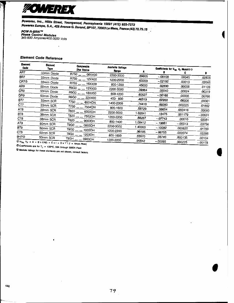
rOWEREX P^l'^fl !E? Y°UngWOOd- *""-*•* 15697(412) 925-7272
POW-R-BRIKT" Phase Control Modules 345-800 Amperes/400-3000 Volts <
Element Code Reference
Element Code
AR7 BR7
AR9 CR9 DR9 BT7 CT7
©Vx,
Element Type
Comparable Disc Device
_50mm Diode R9G0 18XX0Q
50mm Diode R9G0 _ 22XX00 33mm SCR
33mm SCR
38mm SCR
T7S0 6504DN
T7S0 7504DN
Available Voltage Range
^LDjgde R7S0 08XXÖÖ~~ 2200-3000
— ^^^KZI^ZZ]^m___ 800-1200"
800-1200
400- 800
1400-2200
.89605
.63200
.45000
.39964 .60627 .46319
.74419
Coefficients tor V^, vF Model©® B C
-.08108 .00045 -.02192 .00013 .02800 .00008 .05540 .00024
-.00168 .00005 .02950 .00006 .00380 000325
. VF = A + BxLN(l) + Cxi + Dx/7(| Amps Peak) ©Coefficients are for T, =. 130°C. 50A through 3000A Peak
® Modute ratings for these elements are no, shown, consu«. factory
.02836
.02065
.01128
.00319
.00766
.00061
.01882
448
7<?
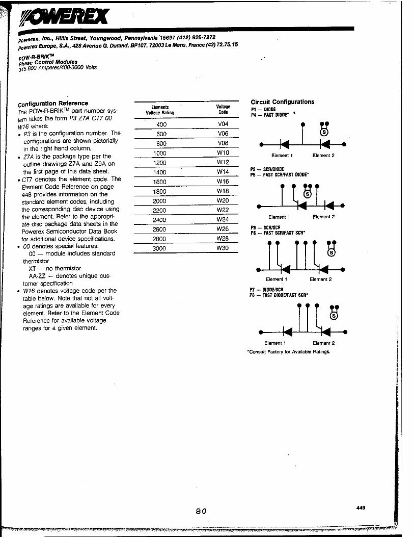
XWEREX powerex, Inc., Mills Street, Youngwood, Pennsylvania 15697 (412) 925-7272 poY/erex Europe, S.A., 428 Avenue G. Durand, BP107, 72003 Le Mans, France(43) 72.75.15
pOW-R-BRIK"1
Phase Control Modules 245-800 Amperes/400-3000 Volts
Configuration Reference The POW-R-BRIK™ part number sys- tem takes the form P3 Z7A CT7 00 VJ16 where: . P3 is the configuration number. The
configurations are shown pictorially in the right hand column.
• Z7A is the package type per the outline drawings Z7A and Z9A on the first page of this data sheet.
• CT7 denotes the element code. The Element Code Reference on page 448 provides information on the standard element codes, including the corresponding disc device using the element. Refer to the appropri- ate disc package data sheets in the Powerex Semiconductor Data Book for additional device specifications.
• 00 denotes special features: 00 — module includes standard
thermistor XT — no thermistor AA-ZZ — denotes unique cus-
tomer specification • W16 denotes voltage code per the
table below. Note that not all volt- age ratings are available for every element. Refer to the Element Code Reference for available voltage ranges for a given element.
Elements Voltage Rating
Voltage Code
400 V04
600 V06
800 V08
1000 W10
1200 W12
1400 W14
1600 W16
1800 W18
2000 W20
2200 W22
2400 W24
2600 W26
2800 W28
3000 W30
Circuit Configurations PI - 0I0DE P4 - FAST DIODE* *
Element 1 Element 2
P2 - SCR/DIODE P5 - FAST SCR/FAST DIODE'
11 ST Element 1 Element 2
P3 - SCR/SCR P6 - FAST SCR/FAST SCR*
It 111 8 Element 1 Element 2
P7 - DIODE/SCR P8 - FAST DIODE/FAST SCR*
* ♦ •
Element 1 Element 2
'Consult Factory for Available Ratings.
80 449
g*WSS?>j!|#gjSsiJSSi&J-l^^ ^^ffig^w^^-^tf^inffre^a^^ fj^r^t^trp^T^-r. «SKS55S5^S?S5W?<s^r«'
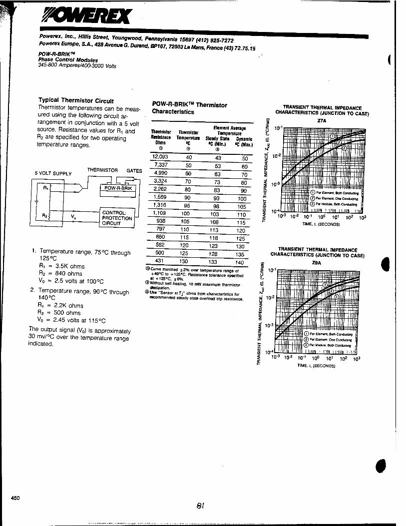
^OWEREX Powerex, Inc., Mills Street, Youngwood, Pennsylvania 15697(412) 925-7272
^ereXEuroPe,S.A.,428AvenueG.Duranä,BP107,72003LeManS,France(43)72.75:i5 POW-R-BRIK™ Phase Control Modules 345-800 Amperes/400-3000 Volts
Typical Thermistor Circuit Thermistor temperatures can be meas- ured using the following circuit ar- rangement in conjunction with a 5 volt source. Resistance values for R, and R2 are specified for two operating temperature ranges.
5 VOLT SUPPLY THERMISTOR GATES
1. Temperature range, 75 °C through 125°C Ri = 3.5K ohms R2 = 840 ohms V0 = 2.5 volts at 100°C
2. Temperature range, 90°C through 140°C Ri = 2.2K ohms R2 = 500 ohms V0 = 2.45 volts at 115°C
The output signal (V0) is approximately 30 mv/°C over the temperature range indicated.
POW-R-BRIK™ Thermistor Characteristics
Element Average nermistor Thermistor Temperature Resistance Temperature Steady State Dynamic
0lm,s *C «C(Mln.) «C(Max.l © ® @
12,093 40 43 50 7,337 50 53 60 4,990 60 63 70 3,324 70 73 80 2,262 80 83 90 1,569 90 93 100 1,316 95 98 105 1,109 100 103 110
938 105 108 115 797 110 113 120 680 115 118 125 582 120 123 130 500 125 128 135 431 130 133 140
©Curve matched ±2% over temperature range of +40°C to + 125°C. Resistance tolerance specified at +125°C, ±6%.
©Without self heating, 10 mW maximum thermistor dissipation.
©Use "Sensor atT," ohms from characteristics for recommended steady state overload trip resistance.
TRANSIENT THERMAL IMPEDANCE CHARACTERISTICS (JUNCTION TO CASE)
Z7A
10-3 102 10-1 10° 101 102 103
TIME, t, (SECONDS)
TRANSIENT THERMAL IMPEDANCE CHARACTERISTICS (JUNCTION TO CASE)
Z9A
10
3 Jjf 10-* z 2 ui
< 10-3
55 10"» 2 10-3
IT
\ t
ißtji iSS^'TTnit 11 1 Ife ILtl |[3) I w
E-|B f PTn l~fl m Iffl J 1 ' i' 'FT
(TW*' 1 1 1 m "''"in iiniir-r llllllli II IE
Z-iit.j Element. One Conducting If It 'HE lit iinun Miiim iimim !i HI'1
10- 10"' 10° 10' 102 103
TIME, t, (SECONDS)
450
81

Appendix E
81
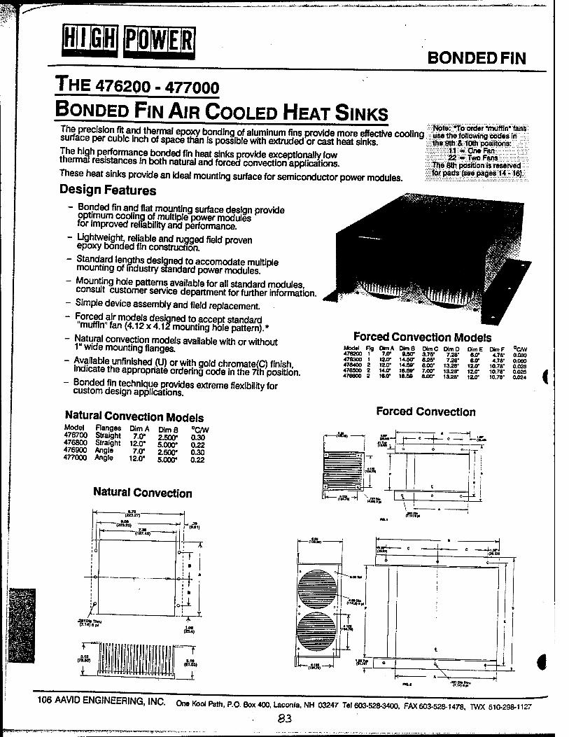
BONDED FIN
THE 476200 - 477000
BONDED FIN AIR COOLED HEAT SINKS 'SSS^RSÜST^ **& bonding* aluminum fins provide more effective cooling WmmSS^SS^ surface per cubic inch of space than is possible with extruded or cast heat sinks. iSS^S' -:
KmS^Ö""3"?6.!?0^60 fln ,neat sinks ProvWe exceptionally low 22 ^ T£ r*k thermal resistances in both natural and forced convection applications. Them^SSSSm^x- These heat sinks provide an ideal mounting surface for semiconductor power modules. tBBM£M~$i:.
Design Features - Bonded fin and flat mounting surface design provide
pptjmum cooling of multiple power modules for improved reliability and performance.
- Lightweight, reliable and rugged field proven epoxy bonded fin construction.
- Standard lengths designed to accomodate multiple mounting of industry standard power modules.
~ ™?!.lng hoJe Patterr,s. available for all standard modules, consult customer service department for further information.
- Simple device assembly and field replacement. ~ w&.^üffiL8 d?signed to accept standard
muffin fan (4.12 x 4.12 mounting hole pattern).*
" ÄÜ22! conve?tio2 models available with or without 1 wide mounting flanges.
" £Ätbie»hTfinished .(U) or with gold chromate(C) finish, indicate the appropnate ordering code in the 7th position.
" SSElSS'jP" technique provides extreme flexibility for custom design applications.
Natural Convection Models ISSSL ?an.9es Dim A DimB °C/W 476700 Straight 7.0" 2500" 030 476800 Straight 12.0" 5.000" 0.22 476900 Angle 7.0" 2.500" 0.30 477000 Angle 12.0" 5.000" 0.22
Natural Convection
Forced Convection Models Model Fig ObnA DimB DimC DimD DimE DlmF °C/W 478200 1 7.0" 9JSV 3.75" 7.28' 8.0" 476300 1 12.0" 14-50" 8.25" 7.28" 8.0* 478400 2 teO" 14.59" 8.00" 13.28" 1Z0" 476900 2 14.0- 18.59* 7.00" 1358* 12.0" 476600 2 16.0" 18£9 8.00* 13.28' 12.0"
Forced Convection
4.78' 0.080 4.78' 0.060
10.78' 0.028 10.78* 0.025 10.78' 0.024 <
I
_ «M (Ml)
,U PU) a pi
(SM)
106 MVID ENGINEERING, INC. One Kool Path, P.O. Box 400, Laconia, NH 03247 Tel 603-528-3400, FAX603-528-1478, TWX 510-298-1127
83
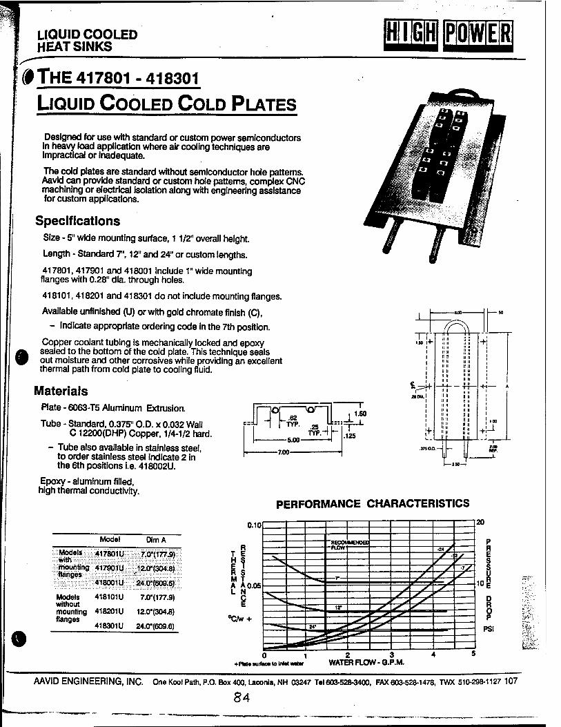
LIQUID COOLED HEAT SINKS
(HTTMlPlöl^
f THE 417801-418301
LIQUID COOLED COLD PLATES
Designed for use with standard or custom power semiconductors in heavy load application where air cooling techniques are Impractical or inadequate.
The cold plates are standard without semiconductor hole patterns. Aavld can provide standard or custom hole patterns, complex CNC machining or electrical isolation along with engineering assistance for custom applications.
Specifications Size - 5" wide mounting surface, 11/2" overall height.
Length - Standard 7', 12" and 24" or custom lengths.
417801,417901 and 418001 include 1" wide mounting flanges with 0.28" dia. through holes.
418101, 418201 and 418301 do not include mounting flanges.
Available unfinished (U) or with gold chromate finish (C),
- Indicate appropriate ordering code in the 7th position.
Copper coolant tubing is mechanically locked and epoxy • sealed to the bottom of the cold plate. This technique seals
out moisture and other corrosives while providing an excellent thermal path from cold plate to cooling fluid.
Materials Plate - 6063-T5 Aluminum Extrusion.
Tube - Standard, 0.375" O.D. x 0.032 Wall C 12200(DHP) Copper, 1/4-1/2 hard.
- Tube also available in stainless steel, to order stainless steel indicate 2 in the 6th positions i.e. 418002U.
Epoxy - aluminum filled, high thermal conductivity.
VH*
TO
1QT—1
-5.00-
.25 TYP.-
«=k T 1.50
-7.00-
.125
jQt
■I n II it ll n
II II II II
3.00
tJ
PERFORMANCE CHARACTERISTICS
9
Model Dim A
Models with mounting flanges
Models without mounting flanges
417801U
417901U
418001Ü
418101U
418201U
418301U
7.0"(177.9)
:;i2.0"(304.8)
24;Ö"(609.6)
7.0*(177.9)
12.0"(304.8)
24.0"(609.6)
0.10 20
P R E S S u
10 §
D R O P
PSI
R T E
in R S M T
["RECON MENOEC ■2AJ* f - %/
y •y —r— x ^- .T:-' 8 d
<
zow
<_l > ^ -y~
V yv < •■*:
j> ''• */ :: ir f S , * fc"r-'.' ■
-V" 'Clw + «^> ^
2*- y^ ~f r; .
.- ;.--f;
&&
-fPtatetuffi 0 KOtolnl«
1 twatM
1
WATE i RFLO W-G.i
i P.M.
4 I 5
AAVID ENGINEERING, INC. One Kool Path, P.O. Box 400, Laconia, NH 03247 Tel 603-528-3400, FAX 603-528-1478, TWX 510-298-1127 107
84
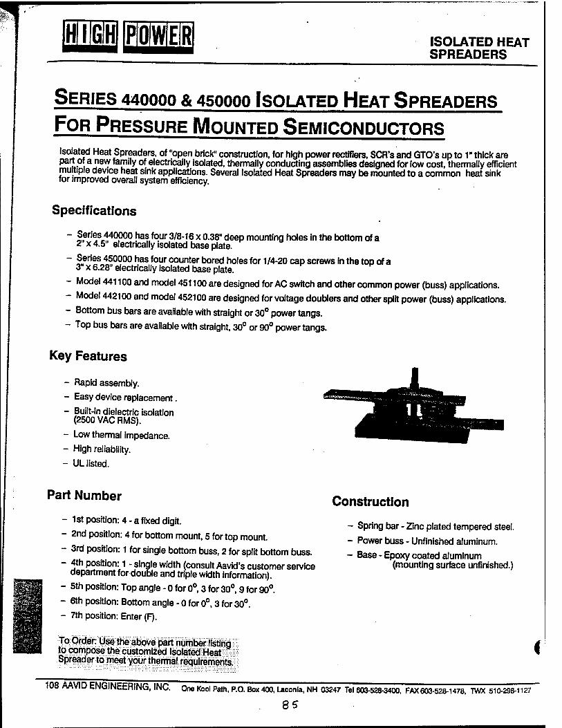
HI QDEUE] ISOLATED HEAT SPREADERS
SERIES 44OOOO & 450000 ISOLATED HEAT SPREADERS
FOR PRESSURE MOUNTED SEMICONDUCTORS Isolated Heat Spreaders, of "open brick" construction, for high power rectifiers, SCR's and GTO's up to 1" thick are part of a new family of electrically isolated, thermally conducting assemblies designed for low cost, thermally efficient multiple device heat sink applications. Several Isolated Heat Spreaders may be mounted to a common heat sink for improved overall system efficiency.
Specifications
- Series 440000 has four 3/8-16 x 0.38" deep mounting holes in the bottom of a 2" x 4.5" electncally isolated base plate.
~ I?"—450?00 has four counter bored holes for 1/4-20 cap screws in the top of a 3" x 6.28" electrically isolated base plate.
- Model 441100 and model 451100 are designed for AC switch and other common power (buss) applications.
- Model 442100 and model 452100 are designed for voltage doublers and other split power (buss) applications.
- Bottom bus bars are available with straight or 30° power tangs.
- Top bus bars are available with straight, 30° or 90° power tangs.
Key Features
- Rapid assembly.
- Easy device replacement.
- Built-in dielectric isolation (2500 VAC RMS).
- Low thermal impedance.
- High reliability.
- UL listed.
Part Number
- 1st position: 4 - a fixed digit.
- 2nd position: 4 for bottom mount, 5 for top mount.
- 3rd position: 1 for single bottom buss, 2 for split bottom buss.
- 4th position: 1 - single width (consult Aavid's customer service department for double and triple width information).
- 5th position: Top angle - 0 for 0°, 3 for 30°, 9 for 90°.
- 6th position: Bottom angle - 0 for 0°, 3 for 30°.
- 7th position: Enter (F).
To Order: Use the above part numberItetihg to compose the customized Isolated Heat Spreader to meet your thermal requirements
Construction
- Spring bar - Zinc plated tempered steel.
- Power buss - Unfinished aluminum.
- Base - Epoxy coated aluminum (mounting surface unfinished.)
<
108 AAVID ENGINEERING, INC. One Kbol Path, P.O. Box 400, Laconia, NH 03247 Tel 603-528-3400, FAX603-528-1478, TWX 510-298-1127
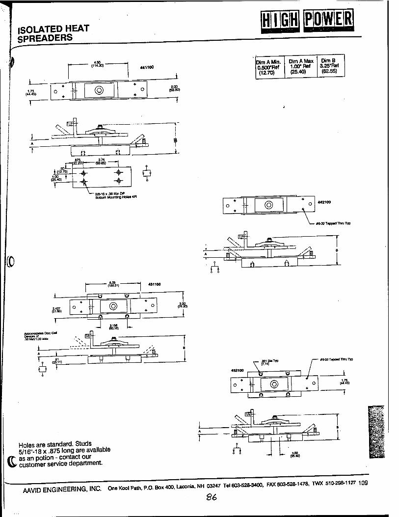
T ISOLATED HEAT SPREADERS
CO
1.75 (44.45)
4.50 . (114.30) 1 441100
®
2.437 (61 X)
«cconoasus Oisc at Devices of .SO MW1.O0 Max
• 3/8-16 x .38 Min DP Bottom Mounting Holes 4pl
. 6.28 . (159.51)
=w ■w
©
—i (80.16) •""
2«L (50.80)
1 3.00
(76 JO)
[iraraB Dim A Min. 0.500"Ref (12.70)
Dim A Max 1.00" Ref (25.40)
DimB 3.25"Ref (82.55)
4- o ® o 442100
- if*32 Tapped thru Typ
__ .281 Dia Typ I
\< 0 1 J #*32 Tapped Thru Typ
(o) 1.75
(44«)
_fi- J°L
Holes are standard. Studs 5/16"-18 x .875 long are available
gh as an potion - contact our UV customer service department.
MVID ENGINEERING, INC. One Kool Path, P, O.Box400,Laconia,NH 03247 Tel 603-528-3400. FAX 603-528-1478, TWX 510-298-1127 109
86

Appendix F
87
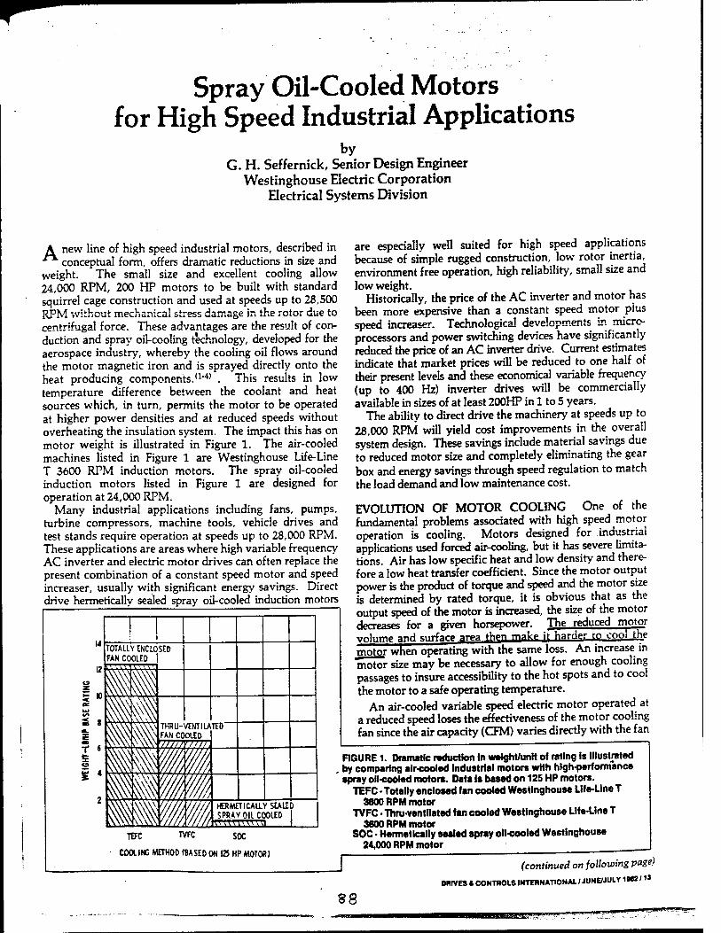
Spray Oil-Cooled Motors for High Speed Industrial Applications
by G. H. Seffernick, Senior Design Engineer
Westinghouse Electric Corporation Electrical Systems Division
A new line of high speed industrial motors, described in *^ conceptual form, offers dramatic reductions in size and weight. The small size and excellent cooling allow 24,000 RPM, 200 HP motors to be built with standard squirrel cage construction and used at speeds up to 28,500 RPM without mechanical stress damage in the rotor due to centrifugal force. These advantages are the result of con- duction and spray oil-cooling technology, developed for the aerospace industry, whereby the cooling oil flows around the motor magnetic iron and is sprayed directly onto the heat producing components.(1"4) . This results in low temperature difference between the coolant and heat sources which, in turn, permits the motor to be operated at higher power densities and at reduced speeds without overheating the insulation system. The impact this has on motor weight is illustrated in Figure 1. The air-cooled machines listed in Figure 1 are Westinghouse Life-Line T 3600 RPM induction motors. The spray oil-cooled induction motors listed in Figure 1 are designed for operation at 24,000 RPM.
Many industrial applications including fans, pumps, turbine compressors, machine tools, vehicle drives and test stands require operation at speeds up to 28,000 RPM. These applications are areas where high variable frequency AC inverter and electric motor drives can often replace the present combination of a constant speed motor and speed increaser, usually with significant energy savings. Direct drive hermetically sealed spray oil-cooled induction motors
are especially well suited for high speed applications because of simple rugged construction, low rotor inertia, environment free operation, high reliability, small size and low weight.
Historically, the price of the AC inverter and motor has been more expensive than a constant speed motor plus speed increaser. Technological developments in micro- processors and power switching devices have significantly reduced the price of an AC inverter drive. Current estimates indicate that market prices will be reduced to one half of their present levels and these economical variable frequency (up to 400 Hz) inverter drives will be commercially available in sizes of at least 200HP in 1 to 5 years.
The ability to direct drive the machinery at speeds up to 28,000 RPM will yield cost improvements in the overall system design. These savings include material savings due to reduced motor size and completely eliminating the gear box and energy savings through speed regulation to match the load demand and low maintenance cost.
EVOLUTION OF MOTOR COOLING One of the fundamental problems associated with high speed motor operation is cooling. Motors designed for industrial applications used forced air-cooling, but it has severe limita- tions. Air has low specific heat and low density and there- fore a low heat transfer coefficient. Since the motor output power is the product of torque and speed and the motor size is determined by rated torque, it is obvious that as the output speed of the motor is increased, the size of the motor decreases for a given horsepower. The reduced motor volume and surface area then make it harder to cooij'ne motor when operating with the same loss. An increase in motor size may be necessary to allow for enough cooling passages to insure accessibility to the hot spots and to cool the motor to a safe operating temperature.
An air-cooled variable speed electric motor operated at a reduced speed loses the effectiveness of the motor cooling fan since the air capacity (CFM) varies directly with the fan
TOC NFC SOC
COOLING METHOD (BASED ON 125 HP MOTOR)
FIGURE 1. Dramatic reduction In weight/unit of rating Is Illustrated by comparing air-cooled industrial motors with high-performance spray oil-cooled motors. Data Is based on 125 HP motors.
TEFC • Totally enclosed fan cooled Westinghouse Lite-Une T 3600 RPM motor
TVFC ■ Thru-ventilated fan cooled Westinghouse Life-Line T 3600 RPM motor
SOC • Hermetically sealed spray oil-cooled Westinghouse 24,000 RPM motor
(continued on following page)
DMVES « CONTROLS IMTEHNATIONAL / JUNE/JULY 19»'«
S8
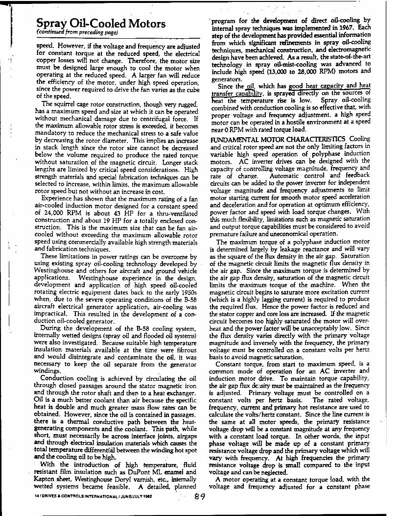
Spray Oil-Cooled Motors (continued from preceding page)
speed. However, if the voltage and frequency are adjusted for constant torque at the reduced speed, the electrical copper losses will not change. Therefore, the motor size must be designed large enough to cool the motor when operating at the reduced speed. A larger fan will reduce the efficiency of the motor, under high speed operation, since the power required to drive the fan varies as the cube of the speed.
The squirrel cage rotor construction, though very rugged, has a maximum speed and size at which it can be operated without mechanical damage due to centrifugal force. If the maximum allowable rotor stress is exceeded, it becomes mandatory to reduce the mechanical stress to a safe value by decreasing the rotor diameter. This implies an increase in stack length since the rotor size cannot be decreased below the volume required to produce the rated torque without saturation of the magnetic circuit. Longer stack lengths are limited by critical speed considerations. High strength materials and special fabrication techniques can be selected to increase, within limits, the maximum allowable rotor speed but not without an increase in cost.
Experience has shown that the maximum rating of a fan air-cooled induction motor designed for a constant speed of 24,000 RPM is about 43 HP for a thru-ventilated construction and about 19 HP for a totally enclosed con- struction. This is the maximum size that can be fan air- cooled without exceeding the maximum allowable rotor speed using commercially available high strength materials and fabrication techniques.
These limitations in power ratings can be overcome by using existing spray oil-cooling technology developed by Westinghouse and others for aircraft and ground vehicle applications. Westinghouse experience in the design, development and application of high speed oil-cooled rotating electric equipment dates back to the early 1950s when, due to the severe operating conditions of the B-58 aircraft electrical generator application, air-cooling was impractical. This resulted in the development of a con- duction oil-cooled generator.
During the development of the B-58 cooling system, internally wetted designs (spray oil and flooded oil systems) were also investigated. Because suitable high temperature insulation materials available at the time were fibrous and would disintegrate and contaminate the oil, it was necessary to keep the oil separate from the generator windings.
Conduction cooling is achieved by circulating the oil through closed passages around the stator magnetic iron and through the rotor shaft and then to a heat exchanger. Oil is a much better coolant than air because the specific heat is double and much greater mass flow rates can be obtained. However, since the oil is contained in passages, there is a thermal conductive path between the heat- generating components and the coolant. This path, while short, must necessarily be across interface joints, airgaps and through electrical insulation materials which causes the total temperature differential between the winding hot spot and the cooling oil to be high.
With the introduction of high temperature, fluid resistant film insulation such as DuPont ML enamel and Kapton sheet, Westinghouse Doryl varnish, etc, internally wetted systems became feasible. A detailed, planned 14/ DRIVES » CONTROLS INTERNATIONAL 7 JUNE/JULY 1M2 §^
program for the development of direct oil-cooling by internal spray techniques was implemented in 1967. Each step of the development has provided essential information from which significant refinements in spray oil-cooling techniques, mechanical construction, and electromagnetic design have been achieved. As a result, the state-of-the-art technology in spray oil-mist-cooling was advanced to include high speed (13,000 to 28,000 RPM) motors and generators.
Since the oil, which has pood heat capacity and heat transfer capability, is sprayed directly on the sources of heat the temperature rise is low. Spray oil-cooling combined with conduction cooling is so effective that, with proper voltage and frequency adjustment, a high speed motor can be operated in a hostile environment at a speed near 0 RPM with rated torque load.
FUNDAMENTAL MOTOR CHARACTERISTICS Cooling and critical rotor speed are not the only limiting factors in variable high speed operation of polyphase induction motors. AC inverter drives can be designed with the capacity of controlling voltage magnitude, frequency and rate of change. Automatic control and feedback circuits can be added to the power inverter for independent voltage magnitude and frequency adjustments to limit motor starting current for smooth motor speed acceleration and deceleration and for operation at optimum efficiency, power factor and speed with load torque changes. With this much flexibility, limitations such as magnetic saturation and output torque capabilities must be considered to avoid premature failure and uneconomical operation.
The maximum torque of a polyphase induction motor is determined largely by leakage reactance and will vary as the square of the flux density in the air gap. Saturation of the magnetic circuit limits the magnetic flux density in the air gap. Since the maximum torque is determined by the air gap flux density, saturation of the magnetic circuit limits the maximum torque of the machine. When the magnetic circuit begins to saturate more excitation current (which is a highly lagging current) is required to produce the required flux. Hence the power factor is reduced and the stator copper and core loss are increased. If the magnetic circuit becomes too highly saturated the motor will over- heat and the power factor will be unacceptably low. Since the flux density varies directly with the primary voltage magnitude and inversely with the frequency, the primary voltage must be controlled on a constant volts per hertz basis to avoid magnetic saturation.
Constant torque, from start to maximum speed, is a common mode of operation for an AC inverter and induction motor drive. To maintain torque capability, the air gap flux density must be maintained as the frequency is adjusted. Primary voltage must be controlled on a constant volts per hertz basis. The rated voltage, frequency, current and primary hot resistance are used to calculate the volts/hertz constant. Since the line current is the same at all motor speeds, the primary resistance voltage drop will be a constant magnitude at any frequency with a constant load torque. In other words, the input phase voltage will be made up of a constant primary resistance voltage drop and the primary voltage which will vary with frequency. At high frequencies the primary resistance voltage drop is small compared to the input voltage and can be neglected.
A motor operating at a constant torque load, with the voltage and frequency adjusted for a constant phase
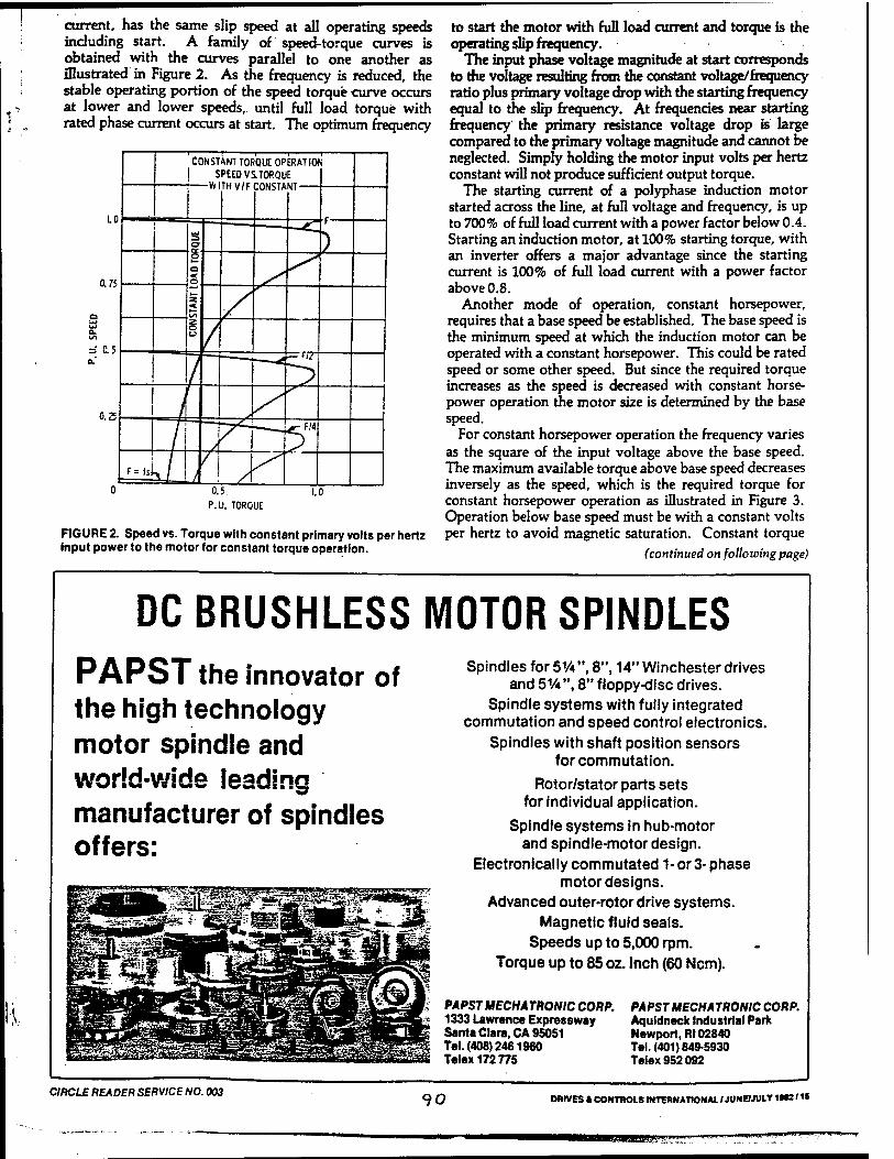
current, has the same slip speed at all operating speeds including start. A family of speed-torque curves is obtained with the curves parallel to one another as illustrated in Figure 2. As the frequency is reduced, the stable operating portion of the speed torque curve occurs at lower and lower speeds,, until full load torque with rated phase current occurs at start. The optimum frequency
P.U. TORQUE
FIGURE 2. Speed vs. Torque with constant primary volts per hertz input power to the motor for constant torque operation.
to start the motor with full load current and torque is the operating slip frequency.
The input phase voltage magnitude at start corresponds to the voltage resulting from the constant voltage/frequency ratio plus primary voltage drop with the starting frequency equal to the slip frequency. At frequencies near starting frequency the primary resistance voltage drop is large compared to the primary voltage magnitude and cannot be neglected. Simply holding the motor input volts per hertz constant will not produce sufficient output torque.
The starting current of a polyphase induction motor started across the line, at full voltage and frequency, is up to 700% of full load current with a power factor below 0.4. Starting an induction motor, at 100% starting torque, with an inverter offers a major advantage since the starting current is 100% of full load current with a power factor above 0.8.
Another mode of operation, constant horsepower, requires that a base speed be established. The base speed is the minimum speed at which the induction motor can be operated with a constant horsepower. This could be rated speed or some other speed. But since the required torque increases as the speed is decreased with constant horse- power operation the motor size is determined by the base speed.
For constant horsepower operation the frequency varies as the square of the input voltage above the base speed. The maximum available torque above base speed decreases inversely as the speed, which is the required torque for constant horsepower operation as illustrated in Figure 3. Operation below base speed must be with a constant volts per hertz to avoid magnetic saturation. Constant torque
(continued on following page)
DC BRUSHLESS MOTOR SPINDLES PAPST the innovator of the high technology motor spindle and world-wide leading manufacturer of spindles offers:
Spindles for 5VA ", 8", 14" Winchester drives and 5V*", 8" floppy-disc drives.
Spindle systems with fully integrated commutation and speed control electronics.
Spindles with shaft position sensors for commutation.
Rotor/stator parts sets for individual application.
Spindle systems in hub-motor and spindle-motor design.
Electronically commutatedl-or 3-phase motor designs.
Advanced outer-rotor drive systems. Magnetic fluid seals.
Speeds up to 5,000 rpm. Torque up to 85 oz. inch (60 Ncm).
PAPST MECHATRONIC CORP. 1333 Lawrence Expressway Santa Clara, CA 95051 Tel.(408)2461960 Telex 172775
PAPST MECHATRONIC CORP. Aquidneck Industrial Park Newport, Rt 02840 Tel.(401)849-5930 Telex 952 092
CIRCLE READER SERVICE NO. 003 90 DRIVES » CONTROLS INTERNATIONAL / JUNE/JULY «K'«
aagg»-';' ■■ '
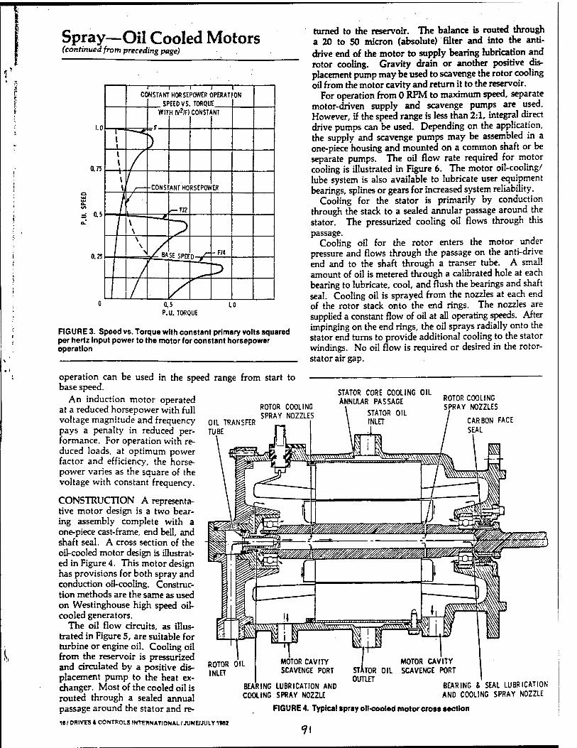
Spray—Oil Cooled Motors (continued from preceding page)
0,5 P.U. TORQUE
FIGURE 3. Speed vs. Torque with constant primary volts squared per hertz Input power to the motor for constant horsepower operation
operation can be used in the speed range from start to base speed.
An induction motor operated at a reduced horsepower with full voltage magnitude and frequency pays a penalty in reduced per- formance. For operation with re- duced loads, at optimum power factor and efficiency, the horse- power varies as the square of the voltage with constant frequency.
turned to the reservoir. The balance is routed through a 20 to 50 micron (absolute) filter and into the anti- drive end of the motor to supply bearing lubrication and rotor cooling. Gravity drain or another positive dis- placement pump may be used to scavenge the rotor cooling oil from the motor cavity and return it to the reservoir.
For operation from 0 RPM to maximum speed, separate motor-driven supply and scavenge pumps are used. However, if the speed range is less than 2:1, integral direct drive pumps can be used. Depending on the application, the supply and scavenge pumps may be assembled in a one-piece housing and mounted on a common shaft or be separate pumps. The oil flow rate required for motor cooling is illustrated in Figure 6. The motor oil-cooling/ lube system is also available to lubricate user equipment bearings, splines or gears for increased system reliability.
Cooling for the stator is primarily by conduction through the stack to a sealed annular passage around the stator. The pressurized cooling oil flows through this passage.
Cooling oil for the rotor enters the motor under pressure and flows through the passage on the anti-drive end and to the shaft through a transer tube. A small amount of oil is metered through a calibrated hole at each bearing to lubricate, cool, and flush the bearings and shaft seal. Cooling oil is sprayed from the nozzles at each end of the rotor stack onto the end rings. The nozzles are supplied a constant flow of oil at all operating speeds. After impinging on the end rings, the oil sprays radially onto the stator end turns to provide additional cooling to the stator windings. No oil flow is required or desired in the rotor- stator air gap.
OIL TRANSFER
ROTOR COOLING SPRAY NOZZLES
STATOR CORE COOLING OIL ANNULAR PASSAGE
STATOR OIL INLET
1
ROTOR COOLING RAY NOZZLES
CARBON FACE
SEAL
CONSTRUCTION A representa- tive motor design is a two bear- ing assembly complete with a one-piece cast-frame, end bell, and shaft seal. A cross section of the oU-cooled motor design is illustrat- ed in Figure 4. This motor design has provisions for both spray and conduction oil-cooling. Construc- tion methods are the same as used on Westinghouse high speed oil- cooled generators.
The oil flow circuits, as illus- trated in Figure 5, are suitable for turbine or engine oil. Cooling oil from the reservoir is pressurized and circulated by a positive dis- placement pump to the heat ex- changer. Most of the cooled oil is routed through a sealed annual passage around the stator and re-
is I DRIVES t CONTROLS INTERNATIONAL / JUNE/JULY 1»M
ROTOR INLET
BEARING COOLING
LUBRICATION AND SPRAY NOZZLE
BEARING & SEAL LUBRICATION ANO COOLING SPRAY NOZZLE
FIGURE 4. Typical spray oil-cooled motor cross section
«?i
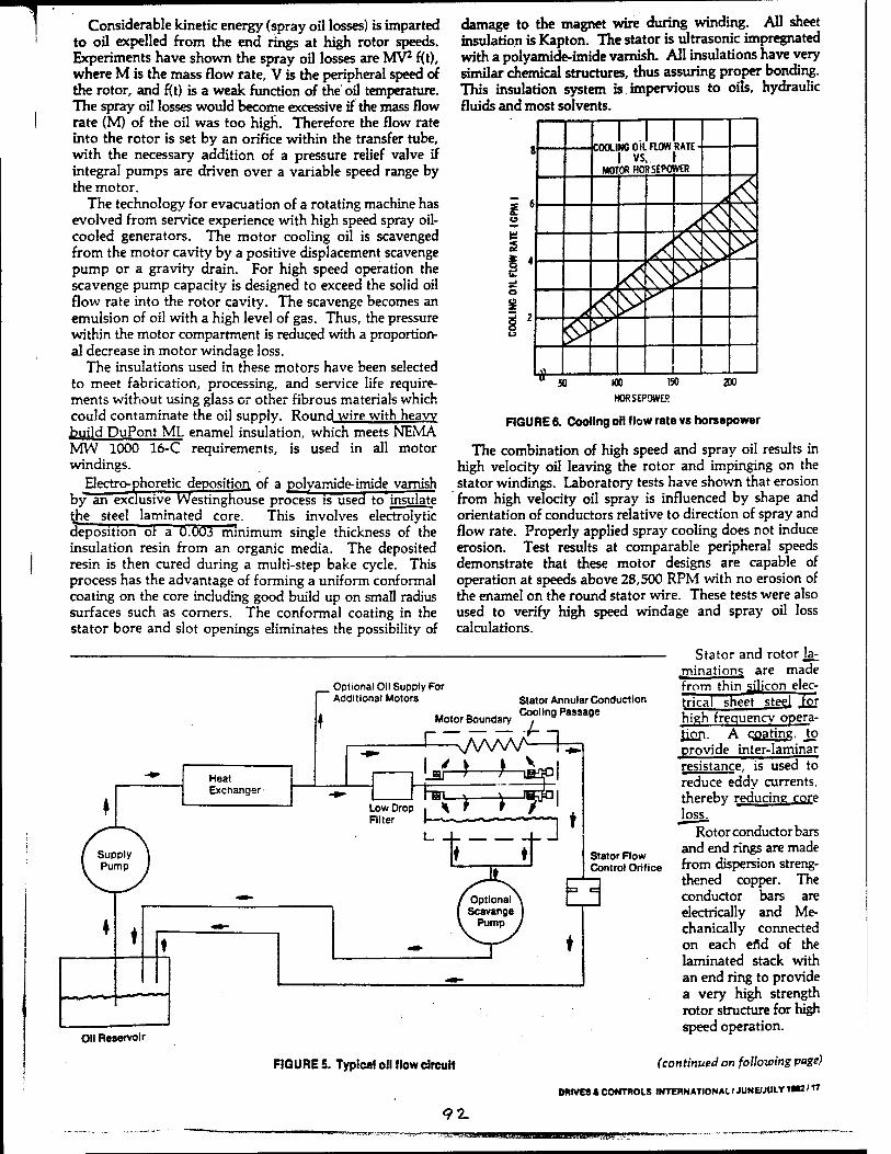
T Considerable kinetic energy (spray oil losses) is imparted to oil expelled from the end rings at high rotor speeds. Experiments have shown the spray oil losses are MV2 f(t), where M is the mass flow rate, V is the peripheral speed of the rotor, and f(t) is a weak function of the oil temperature. The spray oil losses would become excessive if the mass flow rate (M) of the oil was too high. Therefore the flow rate into the rotor is set by an orifice within the transfer tube, with the necessary addition of a pressure relief valve if integral pumps are driven over a variable speed range by the motor.
The technology for evacuation of a rotating machine has evolved from service experience with high speed spray oil- cooled generators. The motor cooling oil is scavenged from the motor cavity by a positive displacement scavenge pump or a gravity drain. For high speed operation the scavenge pump capacity is designed to exceed the solid oil flow rate into the rotor cavity. The scavenge becomes an emulsion of oil with a high level of gas. Thus, the pressure within the motor compartment is reduced with a proportion- al decrease in motor windage loss.
The insulations used in these motors have been selected to meet fabrication, processing, and service life require- ments without using glass or other fibrous materials which could contaminate the oil supply. Round wire with heavy build DuPont ML enamel insulation, which meets NEMA MW 1000 16-C requirements, is used in all motor windings.
Electrc-phoretic deposition of a polyamide-imide varnish by an exclusive Westinghouse process is used to insulate the steel laminated core. This involves electrolytic deposition ot a 0.003 minimum single thickness of the insulation resin from an organic media. The deposited resin is then cured during a multi-step bake cycle. This process has the advantage of forming a uniform conformal coating on the core including good build up on small radius surfaces such as corners. The conformal coating in the stator bore and slot openings eliminates the possibility of
damage to the magnet wire during winding. All sheet insulation is Kapton. The stator is ultrasonic impregnated with a polyamide-imide varnish. All insulations have very similar chemical structures, thus assuring proper bonding. This insulation system is impervious to oils, hydraulic fluids and most solvents.
1 1 1 8 1 vs. \
MOTOR HORSEPOWER
>< <S t 6 (9
V<5 £ ̂ 2 ^
_l P O
i2 u
■rt
8 5. ) WO ISO
HORSEPOWER
200
FIGURE 6. Cooling oil flow rate vs horsepower
The combination of high speed and spray oil results in high velocity oil leaving the rotor and impinging on the stator windings. Laboratory tests have shown that erosion from high velocity oil spray is influenced by shape and orientation of conductors relative to direction of spray and flow rate. Properly applied spray cooling does not induce erosion. Test results at comparable peripheral speeds demonstrate that these motor designs are capable of operation at speeds above 28,500 RPM with no erosion of the enamel on the round stator wire. These tests were also used to verify high speed windage and spray oil loss calculations.
f__ Optional Oil Supply For "~~ Additional Motors
Heat Exchanger
Stator Annular Conduction .. . r, _, Cooling Passage Motor Boundary ,
Oil Reservoir
FIGURES. Typical oil »lowcircuit
Stator and rotor la- minations are made from thin silicon elec- trical sheet steel high frequency opera- tion. A coating, Jo provide inter-laminar resistance, is used to reduce eddy currents, thereby reducing core loss.
Rotor conductor bars and end rings are made from dispersion streng- thened copper. The conductor bars are electrically and Me- chanically connected on each efid of the laminated stack with an end ring to provide a very high strength rotor structure for high speed operation.
(continued on following page)
DRIVES I CONTROLS INTERNATIONAL / JUNE/JULY IM /17
Stator Flow Control Orifice
91 ... '-JJ.lJ.il! mnut,
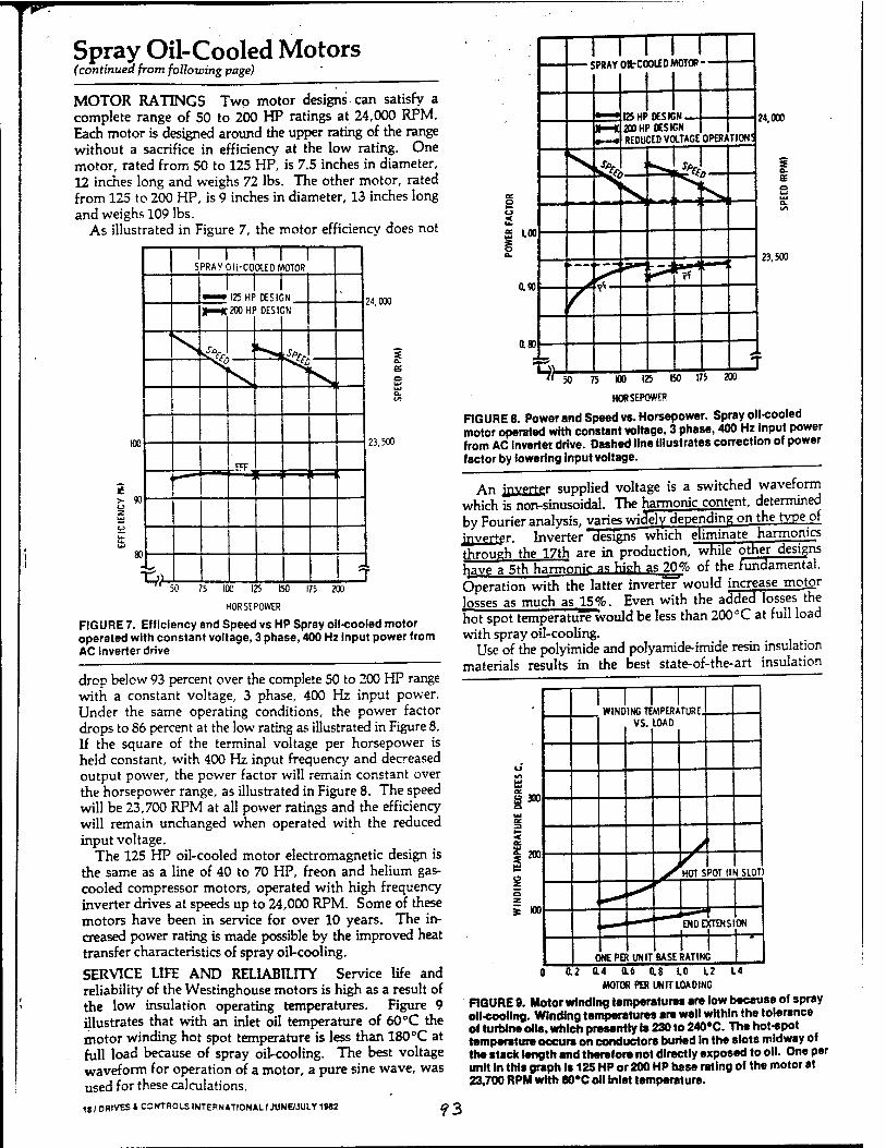
^
Spray Oil-Cooled Motors (continued from following page)
MOTOR RATINGS Two motor designs can satisfy a complete range of 50 to 200 HP ratings at 24,000 RPM. Each motor is designed around the upper rating of the range without a sacrifice in efficiency at the low rating. One motor, rated from 50 to 125 HP, is 7.5 inches in diameter, 12 inches long and weighs 72 lbs. The other motor, rated from 125 to 200 HP, is 9 inches in diameter, 13 inches long and weighs 109 lbs.
As illustrated in Figure 7, the motor efficiency does not
24,000
es
23.500
50 75 100 125 150 175 200
HORSEPOWER
2 LOO
0.«
0.80
• SPRAY OltCOOLED MOTOR - -
^-«
125 HP DESIGN 200 HP DESIGN REDUCED VOLTAGE OPERATION!
24,000
23.500
FIGURE 7. Efficiency and Speed vs HP Spray oil-cooled motor operated with constant voltage, 3 phase, 400 Hz input power from AC inverter drive
drop below 93 percent over the complete 50 to 200 HP range with a constant voltage, 3 phase, 400 Hz input power. Under the same operating conditions, the power factor drops to 86 percent at the low rating as illustrated in Figure 8. If the square of the terminal voltage per horsepower is held constant, with 400 Hz input frequency and decreased output power, the power factor will remain constant over the horsepower range, as illustrated in Figure 8. The speed will be 23,700 RPM at all power ratings and the efficiency will remain unchanged when operated with the reduced input voltage.
The 125 HP oil-cooled motor electromagnetic design is the same as a line of 40 to 70 HP, freon and helium gas- cooled compressor motors, operated with high frequency inverter drives at speeds up to 24,000 RPM. Some of these motors have been in service for over 10 years. The in- creased power raring is made possible by the improved heat transfer characteristics of spray oil-cooling.
SERVICE LIFE AND RELIABILITY Service life and reliability of the Westinghouse motors is high as a result of the low insulation operating temperatures. Figure 9 illustrates that with an inlet oil temperature of 60°C the motor winding hot spot temperature is less than 180 °C at full load because of spray oil-cooling. The best voltage waveform for operation of a motor, a pure sine wave, was used for these calculations.
18 / DRIVES * CONTROLS INTERNATIONAL / JUNE/JULY 1982 O ß
ISO I75 200
HORSEPOWER
FIGURE 8. Power and Speed vs. Horsepower. Spray oil-cooled motor operated with constant voltage, 3 phase, 400 Hz input power from AC Inverter drive. Dashed line Illustrates correction of power factor by lowering input voltage.
An jnvejter supplied voltage is a switched waveform which is non-sinusoidal. The harmonic content, determined by Fourier analysis, varies widely depending on the type of inverter. Inverter designs which eliminate harmonics through the 17th are in production, while other designs have a 5th harmrmir as high as 20% of the fundamental. Operation with the latter inverter would increase motor losses as much as 15%. Even with the added losses the hot spot temperature would be less than 200°C at full load with spray oil-cooling.
Use of the polyimide and polyamide-imide resin insulation materials results in the best state-of-the-art insulation
1 1 1 1 WINDING TEMPERATURE.
VS. LOAD
Ui UJ
Ö 300 Q UJ ac
< Uf % 200
I z
HOTS '0T (II i SLOT)
s wo ENDE (TENS! ON
C NEPEf [UNIT 1 1
BASE RATING 0.2 L4 0.4 0.6 0.8 LO L2
MOTOR PER UNIT LOADING
FIGURE 9. Motor winding temperatures are low because of spray oil-cooling. Winding temperatures are well within the tolerance of turbine oil«, which presently Is 230 to 240°C. The hot-spot temperature occurs on conductors buried In the slots midway of the stack length and therefore not directly exposed to oil. One per unit In this graph is 125 HP or 200 HP base rating of the motor at 23,700 RPM wtth 60*C oil Inlet temperature.

Appendix G
94
Speed up to 200000 rpm.
HF- Motorelements from KaVo EWL.
g 9r
Ki
£ gSJL,
HOFER PRECISION TOOL IMPORTS Inc.
Sub 110 NEWPORT CENTER DR., SUITE 200E 9 Leutkirch
NEWPORT BEACH, CA 92660
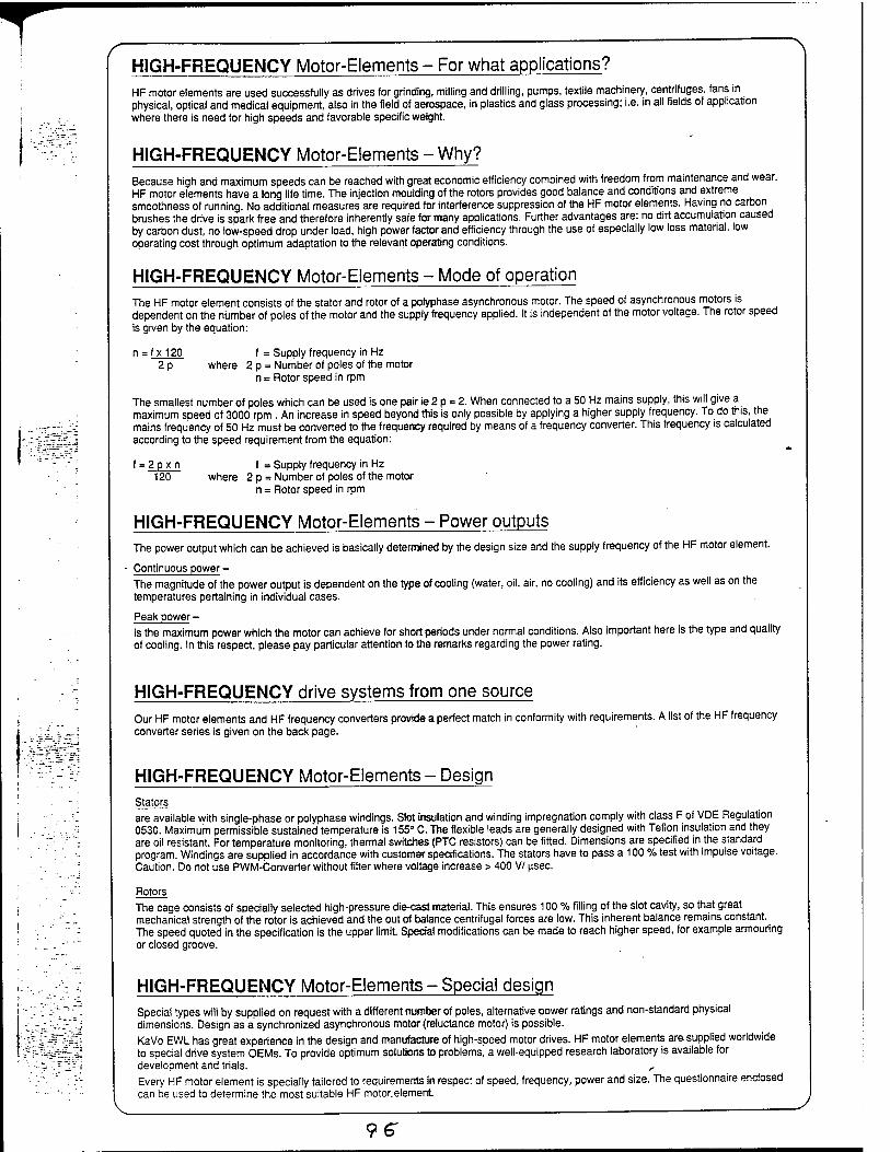
HIGH-FREQUENCY Motor-Elements - For what applications? HF motor elements are used successfully as drives tor grinding, milling and drilling, pumps, textile machinery, centrifuges, fans in physical, optical and medical equipment, also in the field of aerospace, in plastics and glass processing; i.e. in all fields of application where there is need for high speeds and favorable specific weight.
HIGH-FREQUENCY Motor-Elements - Why? Because high and maximum speeds can be reached with great economic efficiency combined with freedom from maintenance and wear. HF motor elements have a long life time. The injection moulding of the rotors provides good balance and conditions and extreme smoothness of running. No additional measures are required for interference suppression of the HF motor elements. Having no carbon brushes the drive is spark free and therefore inherently safe for many applications. Further advantages are: no dirt accumulation caused by carbon dust, no low-speed drop under load, high power factor and efficiency through the use of especially low loss material, low operating cost through optimum adaptation to the relevant operating conditions.
HIGH-FREQUENCY Motor-Elements - Mode of operation The HF motor element consists of the Stator and rotor of a polyphase asynchronous motor. The speed of asynchronous motors is dependent on the number of poles of the motor and the supply frequency applied. It is independent of the motor voltage. The rotor speed is given by the equation:
n = f x 120 f = Supply frequency in Hz 2 p where 2 p = Number of poles of the motor
n = Rotor speed in rpm
The smallest number of poles which can be used is one pair ie 2 p = 2. When connected to a 50 Hz mains supply, this will give a maximum speed of 3000 rpm . An increase in speed beyond this is only possible by applying a higher supply frequency. To do this, the mains frequency of 50 Hz must be converted to the frequency required by means of a frequency converter. This frequency is calculated according to the speed requirement from the equation:
f = 2px n f = Supply frequency in Hz 120 where 2 p = Number of poles of the motor
n = Rotor speed in rpm
HIGH-FREQUENCY Motor-Elements - Power outputs The power output which can be achieved is basically determined by the design size and the supply frequency of the HF motor element.
Continuous power - The magnitude of the power output is dependent on the type of cooling (water, oil, air, no cooling) and its efficiency as well as on the temperatures pertaining in individual cases.
Peak power - is the maximum power which the motor can achieve for short periods under normal conditions. Also important here is the type and quality of cooling. In this respect, please pay particular attention to the remarks regarding the power rating.
HIGH-FREQUENCY drive systems from one source Our HF motor elements and HF frequency converters provide a perfect match in conformity with requirements. A list of the HF frequency converter series is given on the back page.
HIGH-FREQUENCY Motor-Elements - Design Stators are available with single-phase or polyphase windings. Slot insulation and winding impregnation comply with class F of VDE Regulation 0530. Maximum permissible sustained temperature is 155° C. The flexible leads are generally designed with Teflon insulation and they are oil resistant. For temperature monitoring, thermal switches (PTC resistors) can be fitted. Dimensions are specified in the standard program. Windings are supplied in accordance with customer specifications. The stators have to pass a 100 % test with impulse voltage. Caution. Do not use PWM-Converter without filter where voltage increase > 400 VI usec.
Rotors The cage consists of specially selected high-pressure die-cast material. This ensures 100 % filling of the slot cavity, so that great mechanical strength of the rotor is achieved and the out of balance centrifugal forces are low. This inherent balance remains constant. The speed quoted in the specification is the upper limit. Special modifications can be made to reach higher speed, for example armouring or closed groove.
HIGH-FREQUENCY Motor-Elements - Special design Special types will by supplied on request with a different number of poles, alternative power ratings and non-standard physical dimensions. Design as a synchronized asynchronous motor (reluctance motor) is possible. KaVo EWL has great experience in the design and manufacture of high-speed motor drives. HF motor elements are supplied worldwide to special drive system OEMs. To provide optimum solutions to problems, a well-equipped research laboratory is available for development and trials. , Every HF motor element is specially tailored to requirements in respect of speed, frequency, power and size. The questionnaire enclosed can be used to determine the most suitable HF motor.element
96
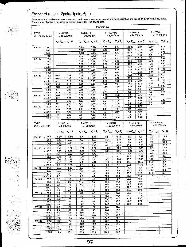
Standard range - 2pole, 4pole, 6pole The values in this table are peak power and continuous power under normal magnetic utilization and based on given frequency steps. The number of poles is indicated by the last digit in the type designation.
l^-l
Power in kW
TYPE 0- Length, poles
f = 250 Hz = 15000/min
Vp«. VH+P2
f = 500 Hz = 30000/min
VP™ vB+p2
f = 1000 Hz = 60000/min
VP™, VP2
f = 1500 Hz = 90000/min
f = 2000Hz = 120000/min
Vp«' VH+P2
EV 30 - 10.2 0,014 0,014 0,05 0.04 0,095 0,07 0,14 0.09
- 20.2 0.045 0,045 0.15 0.11 0,27 0,17 0,38 0.21
- 30.2 0,081 0,076 0,26 0,17 0,45 0,26 0,64 0.32 -
- 40.2 0,12 0,106 0.37 0.23 0.64 0.34 0.9 0.44
EV 40 - 10.2 0.04 0,039 0,13 0,11 0,21 0.18 0,3 0.23
- 20.2 0,12 0,011 0,34 0,28 0,55 0,42 0,75 0.54
- 30.2 0,22 0,19 0,58 0,43 0,92 0,63 1,23 0.81
- 40.2 0,33 0,28 0,85 0,62 1,34 0,91 1,77 1.17
- 50.2 0,44 0,37 1,12 0,79 1,75 1.17 2,29 1,50
- 60.2 0,55 0,45 1,38 0.95 2.13 1,39 2,79 1.79
EV 48 - 15.2 0,05 0,05 0,16 0,15 0,43 0,36 0,68 0,54 0,92 0,7
- 20.2 0,08 0,07 0,24 0,23 0,62 0,50 0.98 0,75 1,3 i 0.97
- 25.2 0,11 0,10 0,34 0,30 0,85 0,66 1,32 0,97 1,74 ' 1,25
- 30.2 0,15 0,14 0,44 0,38 1,08 0,81 1,66 , 1,19 2,19 ; 1.52
- 40.2 0,22 0.21 0,64 0,53 1,54 1,09 2,35 1,6 3,1 ' 2,04
- 50.2 0,3 0,29 0,86 0,68 2,0 1,4 3,0 2,0 4,0 : 2,6
- 60.2 0,39 0.36 1,08 0,83 2,5 1,7 3,8 2.4 4,9 3,15
EV 54 - 15.2 0,06 0,06 0,22 0,20 0,63 0,48 1,0 0,72 1,4 0,93
- 30.2 0,21 0.20 0,71 0,54 1,89 1,13 3,0 1,65 4,0 2.12
- 45.2 0,4 0,36 1,28 0,85 3,3 1,75 5,1 2,54 6,8 3,26
- 60.2 0,6 0,50 1,9 1,16 4,8 2,36 7,5 3.43 9,5 4,38
EV 60 - 20.2 0,2 0,2 0,62 0.54 1,5 1,15 2,3 1,70
- 30.2 0,39 0.37 1,1 0,87 2,7 1,81 4,2 2,65
- 45.2 0,71 i 0,61 2,0 1,37 4,7 2,80 7,2 4,08
- 60.2 1,0 0,85 2,9 1,88 6,8 3,78 10,0 5,5
- 80.2 1.5 1,17 4,2 2,55 9,6 5,10 14,5 7,41
TYPE 0-Length. pole
f = 100Hz = 6000/min
VPm„: Vn+P2
f = 250 = 150
Vn+P™
Hz D0/min
V + P
f = 500 Hz = 30000/min
VP,™,: VR+P2
f = 750 = 45C
vn+p™
Hz 00/min
V + P
f = 100 = 600
V + P vnT 'max
3 Hz 00/min
V + P
EV 70 - 20.2 0,055 j 0,055 0,3 0,30 0,9 0,78 1,6 1,2 2,27 1,65
- 50.2 0,23 ! 0.22 1.2 0,99 3,35 i 2,19 5,6 3,3 7,8 4,41
- 70.2 0,38 ! 0.37 1,9 1,45 5,2 3,15 8,6 4,7 12,0 6,28
-100.2 0,61 0,60 3,0 2,15 8,2 i 4,59 13,5 6,85 18,6 9,10
EV 83 - 15.2 0,07 0.07 0,37 0,37 1,03 i 0,92 1,72 1,44 2,4 1,93
- 30.2 0,26 I 0.25 1,25 1,04 3,25 | 2,26 5,35 3,43 7,35 4,50
- 40.2 0,4 ! 0,39 1,84 1,47 4,7 3,15 7,5 4,75 10,0 6.25
- 55.2 0,63 ! 0,62 2,83 2,04 7,1 4,3 11.3 6,47 15,3 8,5
- 70.2 0,82 0,79 3,55 3,31 8,7 5,39 13,7 6,18 18,6 10,6
- 90.2 1,15 ! 1.07 4,9 4,22 11,8 i 6.94 18,5 10,38 25,0 13,6
-100.2 1,3 : 1,20 5,5 3,7 13,0 7,7 20,5 11,49 27,5 15,0
EV 90 - 40.2 0,55 i 0.52 2,3 1,7 5,7 ! 3,7 9,7 5,6 12,4 7,2
- 60.2 0,90 0.81 4,3 _J 2,8 9,8 : 5,6 15,5 8,4 23,2 11,3
- 80.2 1,4 1,21 6,0 3,8 14,8 ! 7,8 25,0 11,6 31,6 15,1
-100.2 2,0 1.61 8,0 4,7 21,0 10.0 33,0 14,0 41,6 19,0
EV106 - 50.2 1,5 1,3 6,4 4,1 14,0 8,4 23,3 12,6 I - 80.2 2.8 2.3 11,7 6,9 28,2 14,4 37,3 19,8 I -100.2 3,7 2,9 16,3 • 8,9 39,0 18,2 49,0 25,0 I -130.2 5,0 3,9 22,3 11,5 50,0 23,1 72,6 34,0 I
-150.2 6,1 4,5 25,4 13,1 51,5 25.4 94,2 39,5 I
EV120 - 50.2 1,7 1.6 6,6 5,1 15,5 10,5 23,9 15,7
- 60.2 2,0 1,9 7,7 5,7 18,0 11,7 28,0 17,5
- 80.2 3,0 2,6 11,5 7,8 26,6 16,0 41,2 23,7
- 90.2 3,6 3,0 13,5 8,8 31,0 18,0 48,0 27,0
-120.2 5,2 4,2 19,5 12,0 44,6 24,4 68,4 36,2 EV135 - 50.2 2,8 2,5 8,1 7,3 17,6 15,2
- 80.2 5,0 4,5 15,6 12,6 33,6 25,7 -100.2 6,9 6,0 22,0 16,4 42,0 32,0 -125.2 9,0 7.5 26,4 20.0 56,0 40,5 -160.2 12,2 10.0 40,0 26,1 84,0 52,6
EV140 - 50.2 2,7 2.6 10,0 8,2 20,3 16,8
- 80.2 6,1 5,2 20,0 14,9 38,0 28,0 -100.2 8,2 6,8 25,0 18,1 61,0 37,0
■
-125.2 11,0 8.6 34,0 22,4 65,0 42,5 r
-180.2 16,5 12.1 55,0 33,9 120,0 68,0
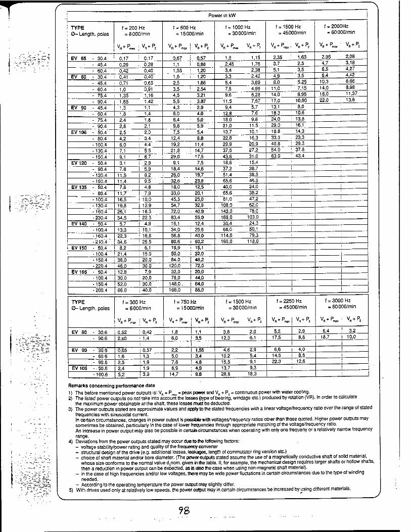
T Power in kW
TYPE 0- Length, poles
f = 200 Hz = 6000/min
VPmax j VP2
f = 500 Hz = 15000/min
V + P i V + P VRT rmax ; R 2
f= 1000 Hz = 30000/min
VP™, VP2
f= 1500 Hz = 45000/min
VR+P^i VR+P2
f = 2000Hz = 60000/min
Vp™„: VR+P2
EV 65 - 30.4 0,17 i 0.17 0,67 i 0,57 1,5 1.15 2,35 ; 1,63 2,95 : 2,08
- 45.4 0,29 i 0.28 1,1 ! 0,88 2,45 1,76 3,7 ! 2.5 4,7 I 3,18
- 60.4 0,42 I 0,40 1,55 ! 1,20 3,4 2,38 5,1 ■■ 3,5 6,5 : 4.27
EV 80 - 30.4 0,41 '■ 0,40 1,5 ; 1,20 3.3 2.42 4.9 ! 3.5 6.4 4.42
- 45.4 0,71 i 0.65 2,5 1,86 5,4 3,69 8,0 : 5,25 10.3 6.66
- 60.4 1,0 i 0,91 3,5 ! 2,54 7,5 4,99 11,0 : 7,15 14,0 8,98
- 75.4 1,35 i 1,16 4,5 3,21 9.6 6,28 14,0 : 8,95 18.0 11,37
- 90.4 1,65 ; 1.42 5,5 : 3,87 11,5 7,57 17,0 10,80 22.0 13,6
EV 90 - 45.4 1,3 ; 1,1 4,3 i 2,9 9,4 5,7 13,1 ; 8,0
- 60.4 1,8 ■ 1,4 6,0 4,0 12,8 7.6 18.3 10.6
- 75.4 2,4 i 1,8 8,4 '■ 5,0 18,0 9.8 24,0 ! 13,8
- 90.4 2,8 ! 2,1 9,8 i 5,9 21,0 11.5 29,0 : 16,1
EV106 - 50.4 2,5 | 2,0 7,5 • 5,4 13,7 10,1 18,8 : 14,3
- 80.4 4,2 : 3,4 12,4 j 8,8 22,8 16.3 33,3 23,3
-100.4 6,0 ! 4,4 19,2 ! 11,4 29,9 20.9 40,8 I 29,3
-130.4 7,1 ! 5,5 21,8 I 14,7 37,5 27,2 54,0 ! 37,8
-150.4 9.1 ! 6.7 29,0 ! 17,5 43,6 31.0 63,0 : 43,4
EV120 - 50.4 3,1 i 2,9 9,1 ! 7,5 18,6 15,4 - 90.4 7,8 ! 5,9 18,4 ! 14,6 37,2 28,7 ! -120.4 11,5 8.2 26,0 ; 19,7 51,4 38.5 -150.4 11,4 9.5 32,6 ! 23,8 65,6 46.5
EV135 - 50.4 7,6 4,8 18,0 I 12,5 40,0 24,0 : - 80.4 11,7 7,9 33,0 I 20,1 65,6 38.2 ' -100.4 16,5 ! 10,0 45,5 ' 25,0 81,0 47,2
1
-130.4 19,8 | 12,9 54,7 ! 32,9 108,0 62,0 1 I
-160.4 26,1 i 16,3 72,0 ! 40,9 143,0 78,0 - 230.4 34,5 ! 22.3 83,4 i 55.0 169,0 103.0 ■
EV140 - 50.4 5,7 | 4.8 16,1 i 12,4 30,4 24,3 ! -100.4 13,3 I 10,1 34,0 I 25,6 68,0 50,1 1 -160.4 22,3 16,8 56,8 ; 40,0 114,0 79,3 1 - 240.4 34,6 25,5 80,6 i 60,2 160,0 118,0 !
EV150 - 50.4 8,2 6.1 19,9 i 15,1 1 I
-100.4 21,4 15,0 50,0 i 32,0 I -150.4 36,0 20,0 84,0 | 48,2 I - 220.4 46,0 I 30.0 120,0 ! 72,0 I
EV165 - 50.4 12,8 ! 7,9 32,0 ! 20,0 I
-100.4 30,0 I 20,0 78,0 f 44,0 ! -150.4 52,0 I 30,0 148,0. ! 64,0 - 200.4 66,0 ! 40,0 168,0 | 85,0
TYPE 0- Length, poles
f = 300 Hz = 6000/min
VPm„ |VR+P2
f = 750 Hz = 15000/min
V + P ! V +P I
f = 1500 Hz = 30000/min
VR+P_ VB+P2
f = 2250 Hz = 45000/min
V + P : v + P VR + rmax ! VR * r2
f = 3000 Hz = 60000/min
VP«. | VR+P2
EV 80 - 30.6 0,52 ! 0,42 1,8 I 1,1 3,6 2,0 5,2 1 2,9 6,4 I 3,2
- 90.6 2,S0 | 1,4 6,0 ! 3,5 12,3 6.1 17,5 i 8,8 18,7 ! 10,0
I I I I
EV 90 - 30.6 0,65 0,57 2,2 I 1,55 4,6 2,9 6,6 i 4,0 | - 60.6 1,6 1,3 5,0 ! 3,4 10,2 5,4 14,5 i 8,8 I
- 90.6 2,5 i 1,9 7,8 ! 4,8 15,5 9,1 22.3 i 12,6 ' EV106 -50.6 2,4 I 1,9 6,9 j 4,9 13,7 9,3 ! !
-100.6 5,2 ! 3,9 14,7 ! 9,8 28,8 18,3 '■
Remarks concerning performance data
1) The before mentioned power outputs is: VR + Pmaj = peak power and VH + P2 = continuous power with water cooling. 2) The listed power outputs do not take into account the losses (type of bearing, windage etc.) produced by rotation (VR). In order to calculate
the maximum power obtainable at the shaft, these losses must be deducted. 3) The power outputs stated are approximate values and appty to the stated frequencies with a linear voltage/frequency ratio over the range of stated
frequencies with sinusoidal current. In certain circumstances, changes in power output is possible with voltages/frequency ratios other than those quoted. Higher power outputs may sometimes be obtained, particularly in the case of lower frequencies through appropriate matching of the voltage/frequency ratio. An increase in power output may also be possible in certain circumstances when operating with only one frequeny or a relatively narrow frequency range.
4) Deviations from the power outputs stated may occur due to the following factors: - voltage stability/power rating and quality of the frequency converter - structural design of the drive (e.g. additional losses, leakages, length of commutator ring version etc.) - choice of shaft material and/or bore diameter. (The power outputs stated assume the use of a magnetically conductive shaft of solid material,
whose size conforms to the normal value d3nom. given in the table. If, for example, the mechanical design requires larger shafts or hollow shafts, then a reduction in power output can be expected, as is also the case when using non-magnetic shaft material).
- in the case of high frequencies and/or low voltages, there may be wide power fluctations in certain circumstances due to the type of winding needed.
- According to the operating temperature the power output may slightly differ. 5) With drives used only at relatively low speeds, the power output may in certain circumstances be increased by using different materials.
?8

Appendix H
9?
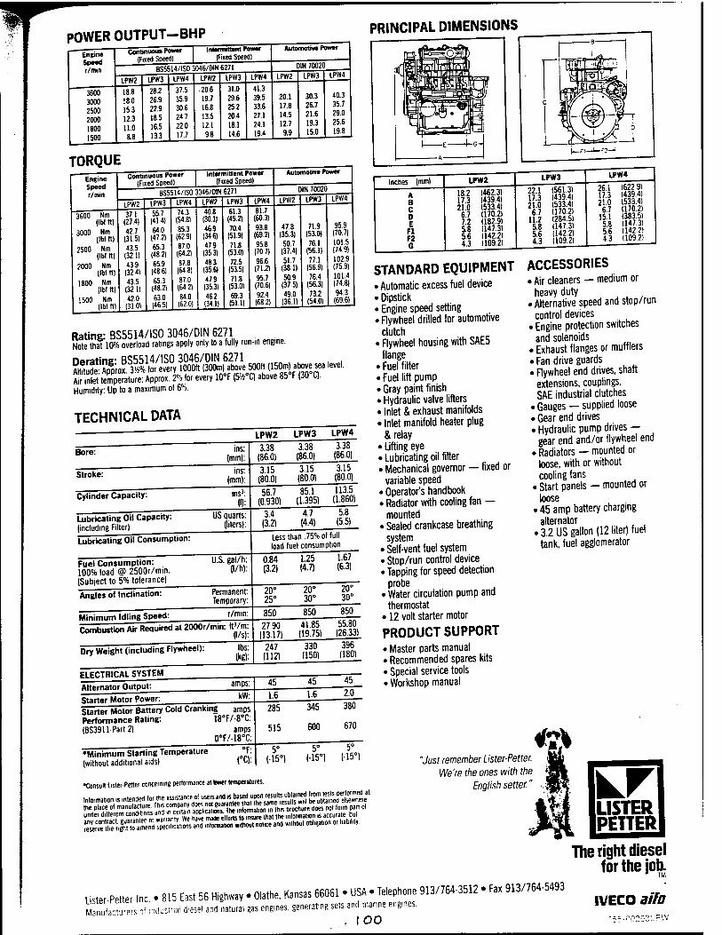
POWER OUTPUT-BHP PRINCIPAL DIMENSIONS
Engine Speed r/min
3600 3000 2500 2000 1800 1500
Continuous Power (Fined Speed) (f i»ed Speed)
BS5514/ISO 3046/DIN 6271
LPW2
18.8 180 153 12.3 11.0
IPW3
28.2 26.9 22.9 18.5 16.5 133
IPW4
37.5 35.9 306 247 22.0 17.7
LPW2
.20.6 19.7 16.8 13.5 121 9.8
LPW3
31.0 29.6 25.2 20.4 18.1 14.6
LPW4
41.3 39.5 33.6 27.1 24.1 19.4
Automotive Power
D1N 70020
LPW2 LPW3 LPW4
20.1 17.8 14.5 12.7 9.9
30.3 26.7 21.6 19.3 15.0
40.3 35.7 29.0 25.6 19.8
TORQUE Engine Speed r/min
Continuou« Power (Fixed Speedl
Intermittent Power IFixed Speed)
BS5514/IS0 3046/DIN 6271
3600 Nm (Ibf ft)
3000 Nm (Ibf ft)
2500 Nm (Ibf ft)
2000 Nm (Ibf ft)
1800 Nm (Ibf ft)
1500 Nm (Ibf ft)
LPW2
37.1 (27.4) 42.7 (315) 43.5
(32.1) 439
(32.4)
43.5 (32.1) 42.0
(31.01
LPW3
55.7 (41.4) 64.0
(47.2) 65.3
(48.2) 65.9
(48.6) 65.3
(48.2) 630 146.5)
LPW4
743 (54.81 853
(62.9) 870 (64a
87.8 (64 81
87.0 (64 2)
84.0 (62.0)
LPW2 40.8
(30.1) 469
(34.6) 479
(35.3) 483
135.6) 47.9
(35.31 462 (34.1)
LPW3
61.3 145.2) 70.4
(51.9) 71.8
(53.0) 72.5
(53.5) 71.8
(53.0) 69.3 (51.1)
LPW4
81.7 [60.31 93.8
(69.2) 95.8 (707)
96.6 (71.2) 95.7
(70.6) 92.4 (682)
Automotive Power
DIN 70020
LPW2 LPW3 LPW4
47.8 (35.3)
50.7 (37.4)
51.7 (38.1)
50.9 (37.5)
49.0 (36.1)
719 95.9 (53.0) ilü.l]
761 101.5 (56.1) (/4.9)
771 102.9 (56.9) l/b.a) 764 101.4
(56.3) 1/4.8)
73 7 94.3 (54.0) (69.61
Rating: BS5514/IS0 3046/DIN 6271 Note that 10% overload ratings apply only to a fully run-in engine.
rwatinsr BS5514/IS0 3046/DIN 6271 , , ^ÄÄ to «er, 1000ft (300m) above 500ft (150m) above, sea level.
Air inlet temperature: Approx. 2% for every 10°F (5»°C) above 85 F (30 C).
Humidity: Up to a maximum of 6%.
TECHNICAL DATA LPW2 LPW3 LPW4
Bore: ins: (mm):
Stroke: ins: (mm):
Cylinder Capacity: ins3: (I):
Lubricating Oil Capacity: (including Filter)
US quarts: (liters):
Lubricating Oil Consumption:
3.38 (86.0)
3.38 (86.0)
3.38 (86.0)
3.15 (80.0)
3.15 (80.0)
56.7 (0.930)
85.1 (1.395)
3.4 (3.2)
4.7 (4.4)
3.15 (80.0) 113.5
(1.860) 5.8
(5.5)
Fuel Consumption: 100% load @ 2500r/min. (Subject to 5% tolerance)
Angles of Inclination:
U.S. gal/h: (l/h):
Less than .75% of full load fuel consumption
Permanent: Temporary:
Minimum Idling Speed: r/min:
Combustion Air Required at 2000r/min: ftVrn:
Dry Weight (including Flywheel): lbs: (kg):
0.84 (3.2)
1.25 (4.7)
1.67 (6.3)
20° 25°
20° 30°
20° 30°
850 850 850
27.90 (13.17)
41.85 (19.75)
247 (112)
330 (150)
55.80 (26.33)
396 (180)
ELECTRICAL SYSTEM
Alternator Output: amps:
Starter Motor Power: kW:
Starter Motor Battery Cold Cranking amps Performance Rating: 18°F/-8°C: |BS3911-Part2) amps
0°F/-18°C
•Minimum Starting Temperature (without additional aids)
°F (°C)
45 45 45
1.6 1.6 2.0
285
515
345
600
380
670
5° (-15°)
5° (•15°)
5° (-15°)
18.2 1462.3) 17.3 1439.4) 21.0 1533.4) 6.7 (170.2) 7.2 (182.9) 5.8 1147.3) 5.6 1142.21 4.3 1109.2)
22.1 (561.3) 17.3 1439.41 21.0 1533.4) 6.7 1170.2)
11.2 (284.51 5.8 IU7.3) 5.6 (142.2) 4.3 (109.2)
26.1 (622-91 17.3 (439.4) 21.0 (533.41 6.7 1170.21
15.1 (383.51 5.8 (147.31 5.6 (142.2) 4.3 1109.2)
STANDARD EQUIPMENT ACCESSORIES > Automatic excess fuel device »Dipstick »Engine speed setting • Flywheel drilled for automotive
clutch • Flywheel housing with SAE5
flange • Fuel filter • Fuel lift pump • Gray paint finish • Hydraulic valve lifters • Inlet & exhaust manifolds • Inlet manifold heater plug
& relay • Lifting eye • Lubricating oil filter • Mechanical governor — fixed or
variable speed e Operator's handbook e Radiator with cooling fan —
mounted • Sealed crankcase breathing
system e Self-vent fuel system • Stop/run control device e Tapping for speed detection
probe e Water circulation pump and
thermostat • 12 volt starter motor
PRODUCT SUPPORT • Master parts manual • Recommended spares kits • Special service tools • Workshop manual
e Air cleaners — medium or heavy duty Alternative speed and stop/run control devices Engine protection switches and solenoids
■ Exhaust flanges or mufflers < Fan drive guards < Flywheel end drives, shaft extensions, couplings, SAE industrial clutches
»Gauges — supplied loose i Gear end drives . Hydraulic pump drives —
gear end and/or flywheel end . Radiators — mounted or
loose, with or without cooling fans
• Start panels — mounted or loose
• 45 amp battery charging alternator
• 3.2 US gallon (12 liter) fuel tank, fuel agglomerator
•Consult ListerPetter concerning performance at kwer temperatures.
Intorma.ron ,s mtended for the ««Unaid use» «-h»WW-«**- KÄ"'
"Just remember Lister-Petter. We're the ones with the
English settef."
The right diesel for the job.
Uster-Petter Inc • 815 East 56 Highway • Olathe, Kansas 66061 • USA -Telephone 913/764-3512 • Fax 913/764-5493
Sacturprs of industna. diesel and natural gas engmes. generatmg sets and manne engines.
, I oo IVECQ aifa
3
*
m
LPA. LPW and LPWS Technical Sales Information
9
027-08247
/Of
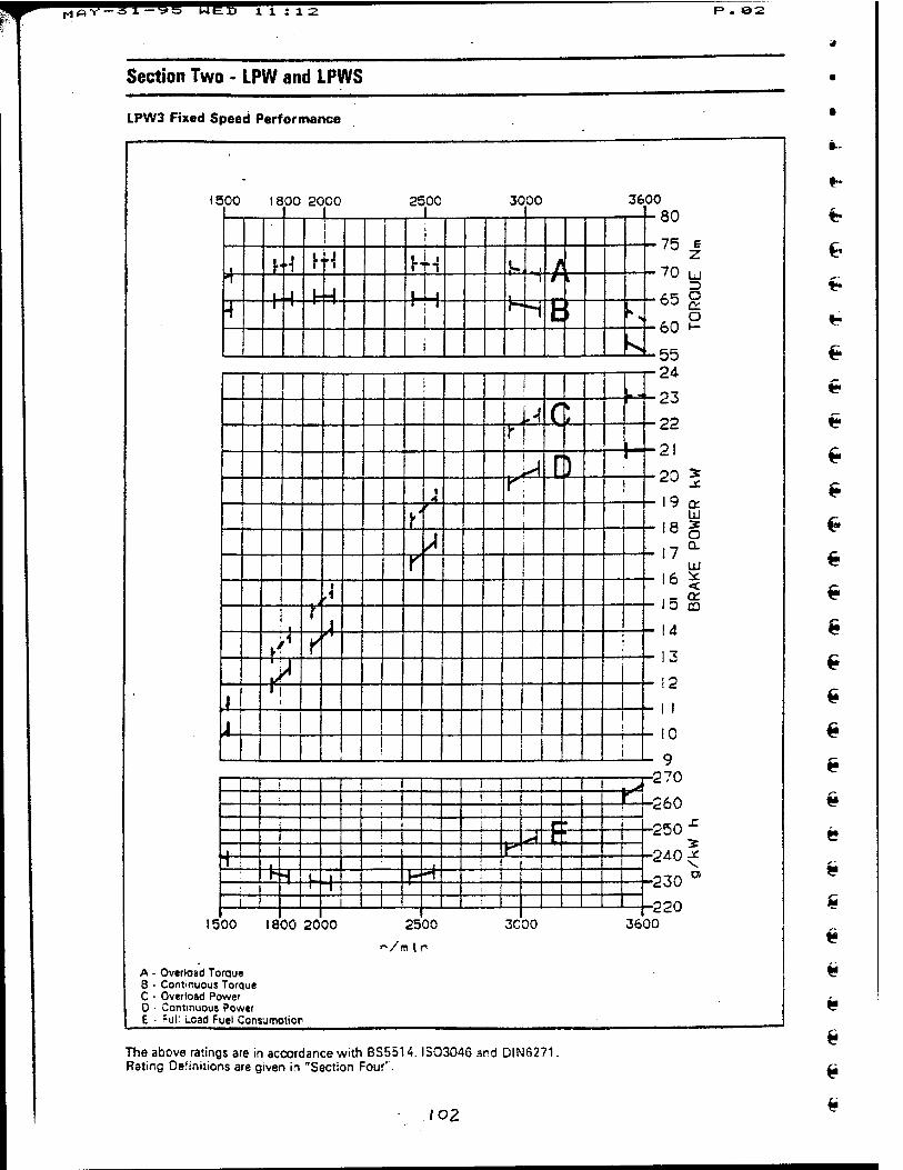
w „^-il-Ut LUD H S12 P . 82
Section Two - LPW and LPWS
LPW3 Fixed Speed Performance
1500
£=c f+ _L
1800 2000
A - Overload TorQue 8 ■ Continuous Torque C • Overload Power D • Continuous Power E ■ fui: i.oad Fuel Consurnoticr
ES
2500
E?
3C00
00 18 00 20 00 2500 |
3000 36
i
1 h 4 y r^ h n i , j fl
*! 1 i u ■4 1 -
i i
4 "T ■T-
i »-H hi >
j V
! 1 L _L_ JdXL X-
p l
It "SlL f . ■- ■' '■ k^ 1 A
-U^ -J~Z -U r ^ -L I-
-LT4- ^ r i S 31 _L IT.
i. ^ ± I I. 4
! ..
80
•75
70
65
60
55 24
£ z U
O a. o
23
22
21
20 •3-
19 a Ixl
18 o 17
Q.
UJ 16 < 15 CO
14
1"*
11
10
n.2 -270
260
-250
-240
-230
5
-220 3600
e * •
is
is
is
if
The above ratings are in accordance with BS5514. ISO3046 and DIN6271. Rating Definitions are given in "Section Four".
loz
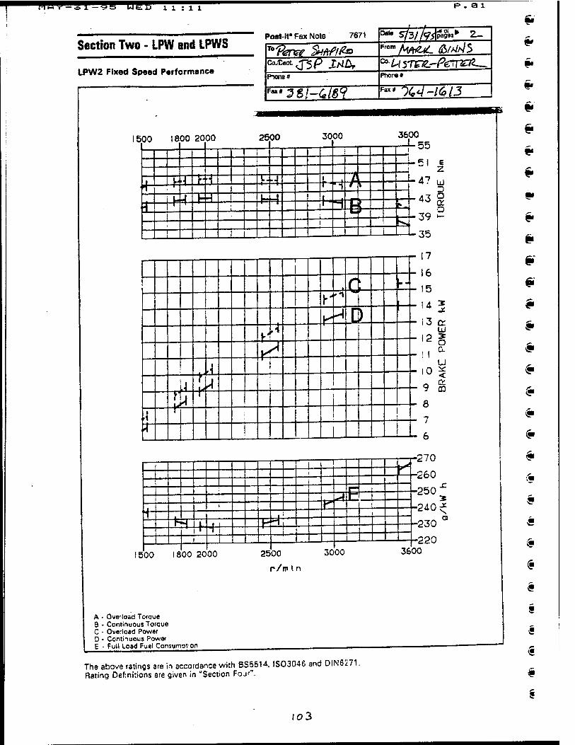
w^nw li:ll
Section Two - LPW and LPWS
LPW2 Fixed Speed Performance
Post-it' Fax Note 7671
1500
T°?W SHMfr CoXeot J"5p Xtlbf PKK18»
Fax« Ztl-lliV
1500 1800 2000
£* F* H
S: 1800 2000
A - Overload Torque 8 - Continuous Toroue C - Overload Power O • Contiiuous Power E - Full Load Fuel Consumption
2500
£3
B±
3000
*a 7- as
EE B
a l
Dato sfe/k&8» From /^^^ ^///A/3
0a-^37ggH%rrE?g~- Phore#
Fa" 9<W-/6/T
2500
r/ro tn
3000
The above ratings are in accordance with BS5514. ISO3046 and DIN6271. Rating Definitions are given in "Section Fojr".
3600 4-55
51
t-4
H
E z
47 u
■43 § o
-J-39 »-
35
-4= T- - ZL JQl i"- Tr^jl , KHD._ . s * ^
4< T i
+ i in L4 L^ _i i +i i
I L_ -1 I I | r f j
-r- 17
6
5
!4 *
13 Q: u
'2g !l a
9 g 8
7
6
■270
-260
•250
•240-^
--230 N a
•220 3600
"m
&
V
«
$
«
6
io3
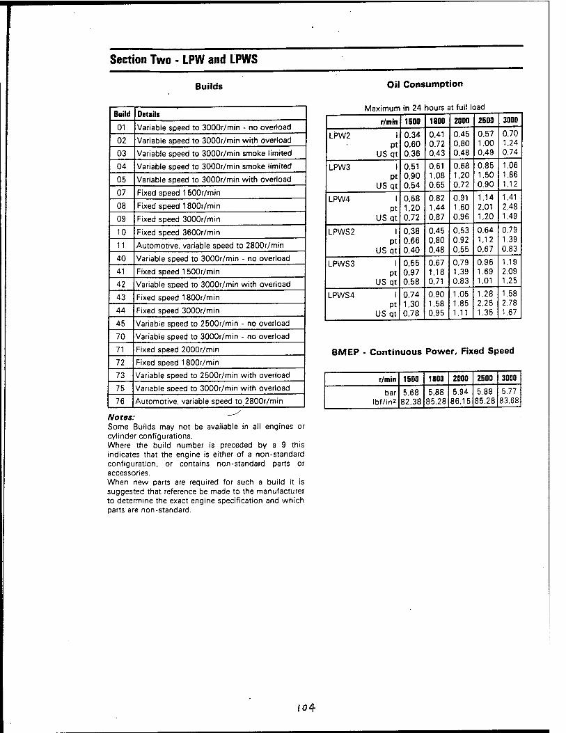
Section Two - LPW and LPWS
Builds Oil Consumption
Build Details
01 Variable speed to 3000r/min - no overload
02 Variable speed to 3000r/min with overload
03 Variable speed to 3000r/min smoke limited
04 Variable speed to 3000r/min smoke limited
05 Variable speed to 3000r/min with overload
07 Fixed speed 1500r/min
08 Fixed speed 1800r/min
09 Fixed speed 3000r/min
10 Fixed speed 3600r/min
11 Automotive, variable speed to 2800r/min
40 Variable speed to 3000r/min - no overload
41 Fixed speed 1500r/min
42 Variable speed to 3000r/min with overload
43 Fixed speed 1800r/min
44 Fixed speed 3000r/min
45 Variable speed to 2500r/min - no overload
70 Variable speed to 3000r/min - no overload
71 Fixed speed 2000r/min
72 Fixed speed 1800r/min
73 Variable speed to 2500r/min with overload
75 Variable speed to 3000r/min with overload
76 Automotive, variable speed to 2800r/min
Notes: Some Builds may not be available in all engines or cylinder configurations. Where the build number is preceded by a 9 this indicates that the engine is either of a non-standard configuration, or contains non-standard parts or accessories. When new parts are required for such a build it is suggested that reference be made to the manufacturer to determine the exact engine specification and which parts are non-standard.
Maximum in 24 hours at full l< Dad
r/min 1500 1800 2000 2500 3000
LPW2 I pt
USqt
0.34 0.60 0.36
0.41 0.72 0.43
0.45 0.80 0.48
0.57 1.00 0.49
0.70 1.24 0.74
LPW3 I Pt
USqt
0.51 0.90 0.54
0.61 1.08 0.65
0.68 1.20 0.72
0.85 1.50 0.90
1.06 1.86 1.12
LPW4 I Pt
US qt
0.68 1.20 0.72
0.82 1.44 0.87
0.91 1.60 0.96
1.14 2.01 1.20
1.41 2.48 1.49
LPWS 2 I Pt
USqt
0.38 0.66 0.40
0.45 0.80 0.48
0.53 0.92 0.55
0.64 1.12 0.67
0.79 1.39 0.83
LPWS 3 I Pt
US qt
0.55 0.97 0.58
0.67 1.18 0.71
0.79 1.39 0.83
0.96 1.69 1.01
1.19 2.09 1.25
LPWS4 I Pt
US qt
0.74 1.30 0.78
0.90 1.58 0.95
1,05 1.85 1.11
1.28 2.25 1.35
1.58 2.78 1.67
BMEP - Continuous Power, Fixed Speed
r/min 1500 1800 2000 2500 3000
bar Ibf/in2
5.68 82.38
5.88 85.28
5.94 86.15
5.88 85.28
5.77 83.68
fo4
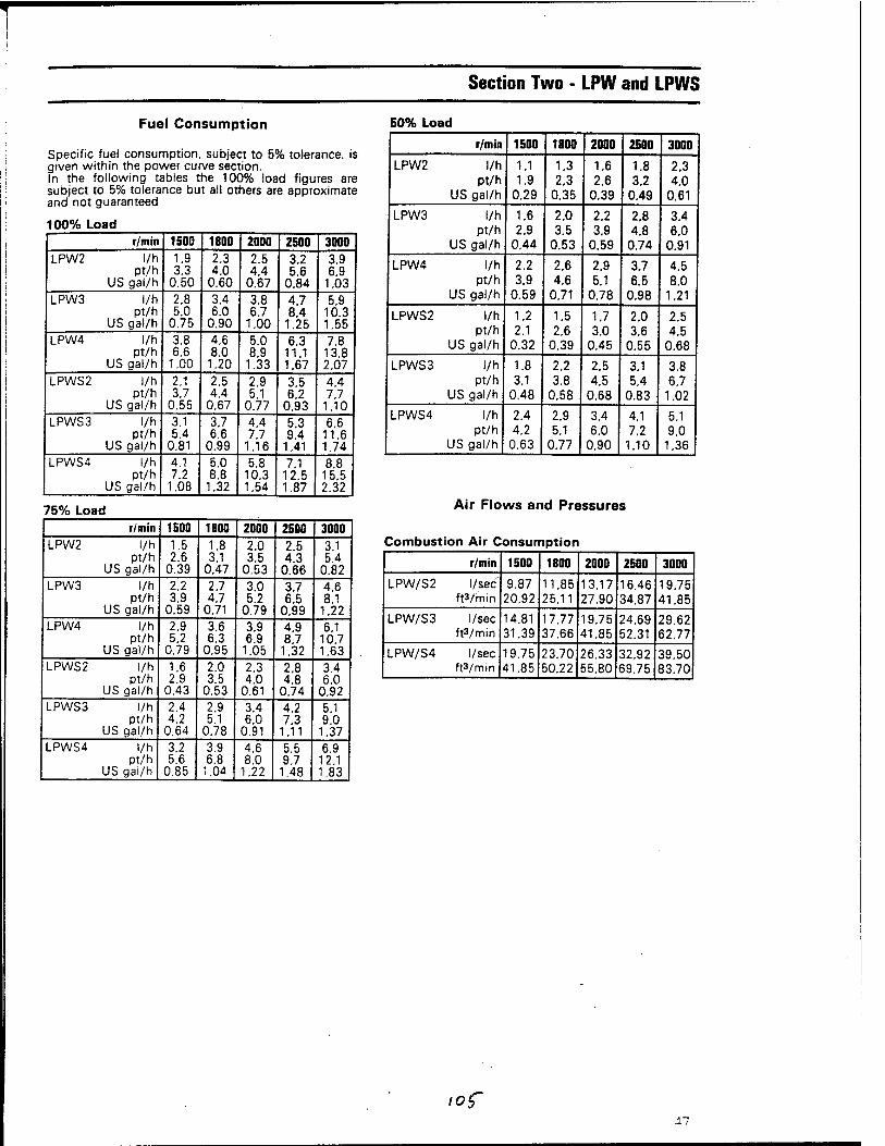
T
Section Two - LPW and LPWS
Fuel Consumption
Specific fuel consumption, subject to 5% tolerance, is given within the power curve section. In the following tables the 100% load figures are subject to 5% tolerance but all others are approximate and not guaranteed
100% Load
50% Load
r/min 1500 1800 2000 2500 3000 LPW2 l/h
pt/h US gal/h
1.9 3.3
0.50
2.3 4.0
0.60
2.5 4.4
0.67
3.2 5.6
0.84
3.9 6.9
1.03 LPW3 l/h
pt/h US gal/h
2.8 5.0
0.75
3.4 6.0
0.90
3.8 6.7
1.00
4.7 8.4
1.25
5.9 10.3 1.55
LPW4 l/h pt/h
US gal/h
3.8 6.6
1.00
4.6 8.0
1.20
5.0 8.9
1.33
6.3 11.1 1.67
7.8 13.8 2.07
LPWS2 l/h pt/h
US gal/h
2.1 3.7
0.55
2.5 4.4
0.67
2.9 5.1
0.77
3.5 6.2
0.93
4.4 7.7
1.10 LPWS3 l/h
pt/h US gal/h
3.1 5.4
0.81
3.7 6.6
0.99
4.4 7.7
1.16
5.3 9.4
1.41
6.6 11.6 1.74
LPWS4 l/h pt/h
US gal/h
4.1 7.2
1.08
5.0 8.8
1.32
5.8 10.3 1.54
7.1 12.5 1.87
8.8 15.5 2.32
75% Load r/min 1500 1800 2000 2500 3000
LPW2 l/h pt/h
US gal/h
1.5 2.6
0.39
1.8 3.1
0.47
2.0 3.5
0.53
2.5 4.3
0.66
3.1 5.4
0.82 LPW3 l/h
pt/h US gal/h
2.2 3.9
0.59
2.7 4.7
0.71
3.0 5.2
0.79
3.7 6.5
0.99
4.6 8.1
1.22 LPW4 l/h
pt/h US gal/h
2.9 5.2
0.79
3.6 6.3
0.95
3.9 6.9
1.05
4.9 8.7
1.32
6.1 10.7 1.63
LPWS2 l/h pt/h
US gal/h
1.6 2.9
0.43
2.0 3.5
0.53
2.3 4.0
0.61
2.8 4.8
0.74
3.4 6.0
0.92 LPWS3 l/h
pt/h US gal/h
2.4 4.2
0.64
2.9 5.1
0.78
3.4 6.0
0.91
4.2 7.3
1.11
5.1 9.0
1.37 LPWS4 l/h
pt/h US gal/h
3.2 5.6
0.85
3.9 6.8
1.04
4.6 8.0
1.22
5.5 9.7
1.48
6.9 12.1 1.83
r/min 1500 1800 2000 2500 3000
LPW2 l/h pt/h
US gal/h
1.1 1.9
0.29
1.3 2.3
0.35
1.6 2.6
0.39
1.8 3.2
0.49
2.3 4.0
0.61
LPW3 l/h pt/h
US gal/h
1.6 2.9
0.44
2.0 3.5
0.53
2.2 3.9
0.59
2.8 4.8
0.74
3.4 6.0
0.91
LPW4 l/h pt/h
US gal/h
2.2 3.9
0.59
2.6 4.6
0.71
2.9 5.1
0.78
3.7 6.5
0.98
4.5 8.0
1.21
LPWS2 l/h pt/h
US gal/h
1.2 2.1
0.32
1.5 2.6
0.39
1.7 3.0
0.45
2.0 3.6
0.55
2.5 4.5
0.68
LPWS3 l/h pt/h
US gal/h
1.8 3.1
0.48
2.2 3.8
0.58
2.5 4.5
0.68
3.1 5.4
0.83
3.8 6.7
1.02
LPWS4 l/h pt/h
US gal/h
2.4 4.2
0.63
2.9 5.1
0.77
3.4 6.0
0.90
4.1 7.2
1.10
5.1 9.0
1.36
Air Flows and Pressures
Combustion Air Consumption
r/min 1500 1800 2000 2500 3000
LPW/S2 l/sec ft3/min
9.87 20.92
11.85 25.11
13.17 27.90
16.46 34.87
19.75 41.85
LPW/S3 l/sec ft3/min
14.81 31.39
17.77 37.66
19.75 41.85
24.69 52.31
29.62 62.77
LPW/S4 l/sec ft3/min
19.75 41.85
23.70 50.22
26.33 55.80
32.92 69.75
39.50 83.70
iof 47

Section Five - Formulae and Conversions
SECTION FIVE - FORMULAE AND CONVERSIONS
Formulae
BMEP Bar = kW x 60000 x 20000 a I — R.VV A \JW\J\J A f-ww
Cylinders x r/min x bore area (mm') x stroke (mm)
Ibf/in* = bhp x 792000 Cylinders x-r/min x bore area (in*) x stroke (in)
Torque Nm =
Ibf ft
kW x 9549 x OL r/min
bhpx 5252 x OL r/min
OL = Overload No overload = 1.0 10% overload = 1.1
Fuel Consumption l/h = o/kWh x kW x L
BIS
pt/h Ib/bho h x bhp x L u55
L = Load (naturally aspirated engines) 100% = 1.0 50% = 0.58 75% = 0.78 25% = 0.40 L = Load (turbocharged engines) 100% =1.0 50% = 0.55 75% = 0.76 25% = 0.38 A Specific Gravity of 0.84 is assumed.
Oil Consumption a/kWhix kW
4661
pt/24h = Ib/bhD h x bho 5.83
Piston Speed m/sec = stroke (mm) x r/min
3ÖÖÖ0
ft/min = stroke (in) x r/min 6
Mechanical Efficiency % = bhp. x 100
ihp
Cyclic Irregularity max flywheel sneed - min flywheel soeed
mean flywheel speed
Power kW =
bhp =
r/min x Toraue(Nm) 9549
r/min x Torauedb ft) 5252
Continuous Power 1bhp =1.014CV = 0.746kW 1kW =1.340bhp =1.359CV 1CV =0.986bhp = 0.736kW
Intermittent Power 1.1 bhp =1.115CV = 0.821 kW 1.1 kW =1.474bhp =1.495CV 1.1 CV =1.085bhp =0.810kW
106
#
c
6

Appendix I
101
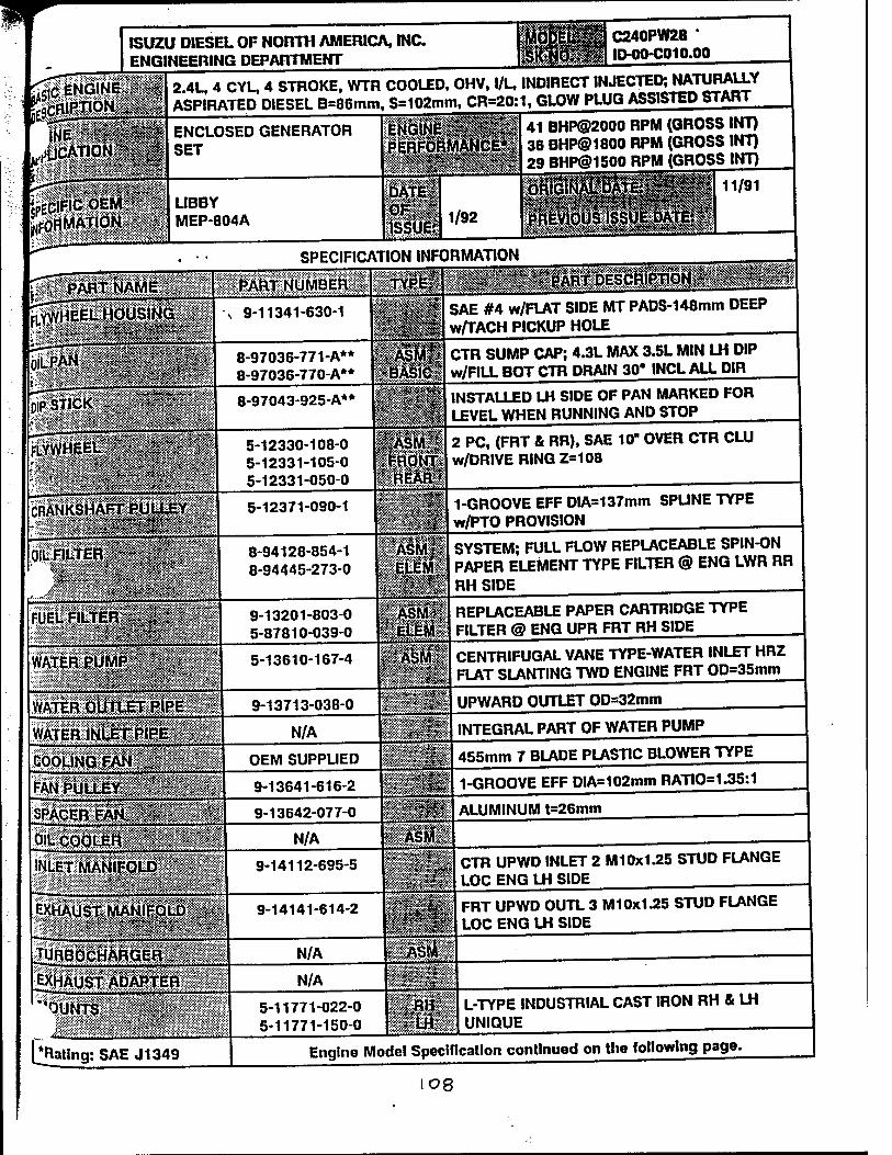
ISUZU DIESEL OF NORTH AMERICA, INC ENGINEERING DEPARTMENT
CENGINEIIS
C240PW28 ' ID-00-C010.00
2.4L, 4 CYL, 4 STROKE, WTR COOLED, OHV, l/L, INDIRECT INJECTED; NATURALLY ASPIRATED DIESEL B=86mm, S=102mm, CR=20;1, GLOW PLUG ASSISTED START
ENCLOSED GENERATOR SET
LIBBY MEP-804A
41 BHP@2000 RPM (GROSS INT) 36 BHPO1800 RPM (GROSS INT) 29 BHP®1500 RPM (GROSS INT)
SPECIFICATION INFORMATION
0ip^RXiÄMlllll;ii»RT:NÜMBE«
s 9-11341-630-1
8-97036-771-A** 8-97036-770-A**
8-97043-925-A**
I--M II
jRANKSHÄFTRÜllEY.,
5-12330-108-0 5-12331-105-0 5-12331-050-0
SAE #4 w/FLAT SIDE MT PADS-148mm DEEP w/TACH PICKUP HOLE
CTR SUMP CAP; 4.3L MAX 3.5L MIN LH DIP w/FILL BOT CTR DRAIN 30* INCL ALL DIR
INSTALLED LH SIDE OF PAN MARKED FOR LEVEL WHEN RUNNING AND STOP
5-12371-090-1
8-94128-854-1 8-94445-273-0
WATER PUMP * ?>* «
ÄSfVl :£ELEMf
iiiirr '"" ^
2 PC, (FRT & RR), SAE 10" OVER CTR CLU w/DRlVE RING Z=108
1-GROOVE EFF DIA=137mm SPUNE TYPE w/PTO PROVISION
SYSTEM; FULL FLOW REPLACEABLE SPIN-ON PAPER ELEMENT TYPE FILTER @ ENG LWR RR RH SIDE
9-13201-803-0 5-87810-039-0
■ lll'llUl'l
WATEROUTLET^RIREII ■■■ ■ *— '-' - --*—
.;S*;
WATER INLET|PjPE«i
COOLING FAN > ;--■-■' T ■....-■■■- — ^
FAN PUU£Y~^Ä^Ä' YiTiViYmr*"""*'**|*.^~.*.****"*"y*v**/.'*'**.*.***.*.*.*.*
5-13610-167-4
9-13713-038-0
N/A
pWs$S$S$
OEM SUPPLIED
REPLACEABLE PAPER CARTRIDGE TYPE FILTER @ ENG UPR FRT RH SIDE
CENTRIFUGAL VANE TYPE-WATER INLET HRZ FLAT SLANTING TWD ENGINE FRT OD=35mm
UPWARD OUTLET OD=32mm
INTEGRAL PART OF WATER PUMP
9-13641-616-2
SPACER FAN v> ^ .^^.....-.-..v.v.y-.v.^Y^,^ Jmssmm 0lL.CpOLER«|pÄf^«i
■' Ki iriimiiMi in miii in <^S«<«ft- """" >■■: *■ :-.::*'<:-'^'-:->:':xV;y^y;:vX::v-;:^:;.i:-:i::.-'
INLETMANIFQLD«M*
9-13642-077-0 ALUMINUM t=26mm
N/A
9-14112-695-5
TURBQCHARGER . TV'.! ■■ ^■^VJA^^uJl^v///^^v'"'".^^^v^^^"^^^^^^^^^^"^^-^'--^^l"
EXHAUST; ADABi:ERiilI: "*" m^^n^^+*i+*+^+***m********f*** ■■"■ ,
N/A
N/A
:5:SSKWKS-
[^Rating: SAEJ1349
5-11771-022-0 5-11771-150-0
455mm 7 BLADE PLASTIC BLOWER TYPE
1-GROOVE EFF DIA=102mm RATIO=1.35:1
CTR UPWD INLET 2 M10x1.25 STUD FLANGE LOC ENG LH SIDE
FRT UPWD OUTL 3 M 10x1.25 STUD FLANGE LOC ENG LH SIDE
L-TYPE INDUSTRIAL CAST IRON RH & LH UNIQUE
Engine Model Specification continued on the following page.
I08
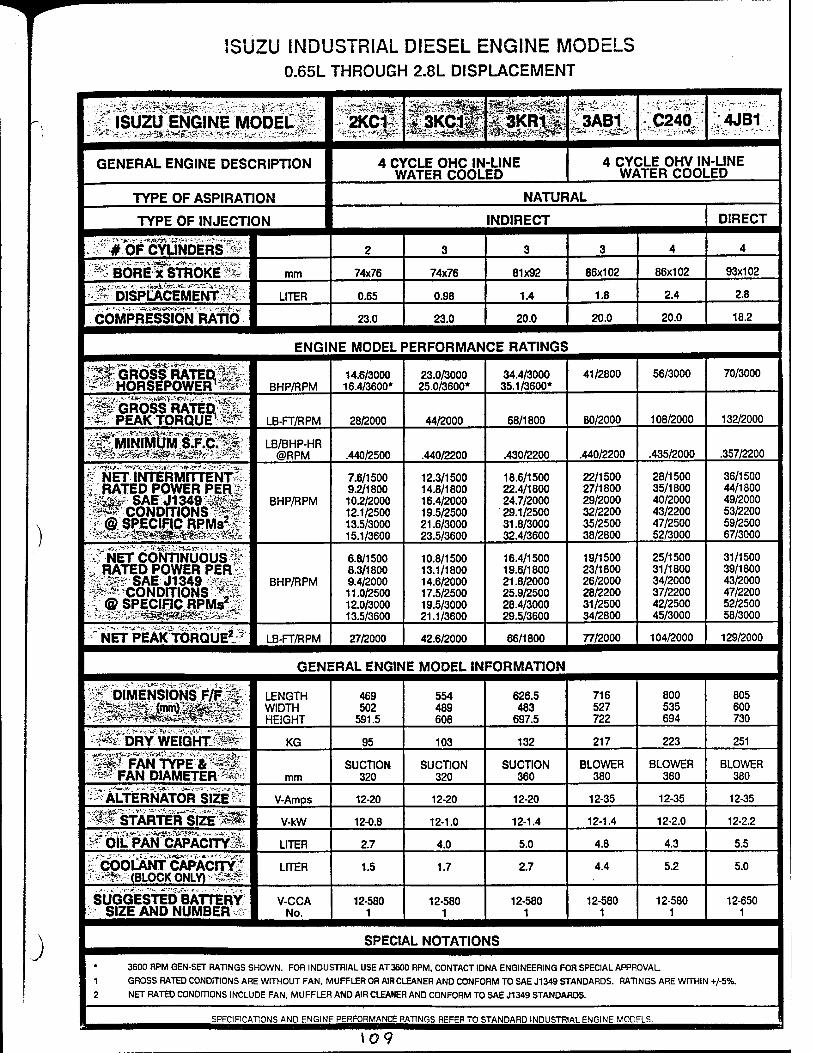
J
ISUZU INDUSTRIAL DIESEL ENGINE MODELS 0.65L THROUGH 2.8L DISPLACEMENT
/ ^UZai^iNiE MODEßfe-: 2KC1Ä v3KC1l C3ÄBI; '^240^ |4JB1
GENERAL ENGINE DESCRIPTION 4 CYCLE OHC IN-LINE WATER COOLED
4 CYCLE OHV IN-LINE WATER COOLED
TYPE OF ASPIRATION NATURAL
TYPE OF INJECTION INDIRECT DIRECT
. # #OFCyUNDERS'Ä; 2 3 3 3 4 4
^ BOREfsTRÖkE^ mm 74x76 74x76 81x92 86x102 86x102 93x102
'-^"blSPLACEliSrÄ"- LITER 0.65 0.98 1.4 1.8 2.4 2.8 -■ '-.'J•■^<*.^•-■■#».^''*lS'^■>H-T*■*•';S'.•:-*^^'■"■!i'!,•■ W ..
COMPRESSION RATIO 23.0 23.0 20.0 20.0 20.0 18.2
ENGI ME MODEL »ERFORMAN CE RATINGS
S^ GROSS* RATEDLgl'' ' -■■'-■'-■ HORSEPOWER1 BHP/RPM
14.6/3000 16.4/3600*
23.0/3000 25.0/3600*
34.4/3000 35.1/3600*
41/2800 56/3000 70/3000
fÄGRlols'RATEä^l'- ^* PEAK TORQUE1 ^?^ LB-FT/RPM 28/2000 44/2000 68/1800 80/2000 108/2000 132/2000
LB/BHP-HR @RPM .440/2500 .440/2200 .430/2200 .440/2200 .435/2000 .357/2200
*f NETlNTÄffiENTf \ RATED POWER PER* ' -M&& SAB J1349%ä£fg i*P?coNDrnoNS^# r@ SPECIFIC RPMÄ
BHP/RPM
7.6/1500 9.2/1800 10.2/2000 12.1/2500 13.5/3000 15.1/3600
12.3/1500 14.8/1800 16.4/2000 19.5/2500 21.6/3000 23.5/3600
18.6/1500 22.4/1800 24.7/2000 29.1/2500 31.8/3000 32.4/3600
22/1500 27/1800 29/2000 32/2200 35/2500 38/2800
28/1500 35/1800 40/2000 43/2200 47/2500 52/3000
36/1500 44/1800 49/2000 53/2200 59/2500 67/3000
NET CONTINUOUS:
■£ RATED POWER PERi :-%38% SAEJ1349 vSSS&ST' #* CONDITIONS m V @ SPECIFIC RPMs2^
BHP/RPM
6.8/1500 8.3/1800 9.4/2000 11.0/2500 12.0/3000 13.5/3600
10.8/1500 13.1/1800 14.6/2000 17.5/2500 19.5/3000 21.1/3600
16.4/1500 19.6/1800 21.8/2000 25.9/2500 28.4/3000 29.5/3600
19/1500 23/1800 26/2000 28/2200 31/2500 34/2800
25/1500 31/1800 34/2000 37/2200 42/2500 45/3000
31/1500 39/1800 43/2000 47/2200 52/2500 58/3000
NET PEAK TORQUEl LB-FT/RPM 27/2000 42.6/2000 66/1800 77/2000 104/2000 129/2000
GEN! ERAL ENGIN E MODEL IN FORMATION
, 2f DIMENSIONS F/F^ LENGTH WIDTH HEIGHT
469 502
591.5
554 489 608
626.5 483
697.5
716 527 722
800 535 694
805 600 730
xl^bl^WEliGlmÄfe' KG 95 103 132 217 223 251
- I^FAN TYPE *^^,-. ^ FAN DIAMETERS* mm
SUCTION 320
SUCTION 320
SUCTION 360
BLOWER 380
BLOWER 380
BLOWER 380
^^Äl?reRNATOR SEEÄ V-Amps 12-20 12-20 12-20 12-35 12-35 12-35
•'-«»STARTER SIZE^Br V-kW 12-0.8 12-1.0 12-1.4 12-1.4 12-2.0 12-2.2
:$?:0]J^N^CAPACHYS; LITER 2.7 4.0 5.0 4.8 4.3 5.5
1 COÖCANT CAPACITY! S^F (BLOCK ONLY) ^^
LITER 1.5 1.7 2.7 4.4 5.2 5.0
SUGGESTED BATTERY SIZE AND NUMBER
V-CCA No.
12-580 1
12-580 1
12-580 1
12-580 1
12-580 1
12-650 1
SPECIAL NOTATIONS
3600 RPM GEN-SET RATINGS SHOWN. FOR INDUSTRIAL USE AT3600 RPM, CONTACT IDNA ENGINEERING FOR SPECIAL APPROVAL
1 GROSS RATED CONDITIONS ARE WITHOUT FAN, MUFFLER OR AIR CLEANER AND CONFORM TO SAE J1349 STANDARDS. RATINGS ARE WITHIN +/-5%.
2 NET RATED CONDITIONS INCLUDE FAN, MUFFLER AND AIR CLEANER AND CONFORM TO SAE J1349 STANDARDS.
SPECIFICATIONS AND ENGINE PERFORMANCE RATINGS REFER TO STANDARD INDUSTRIAL ENGINE MODELS.
\09
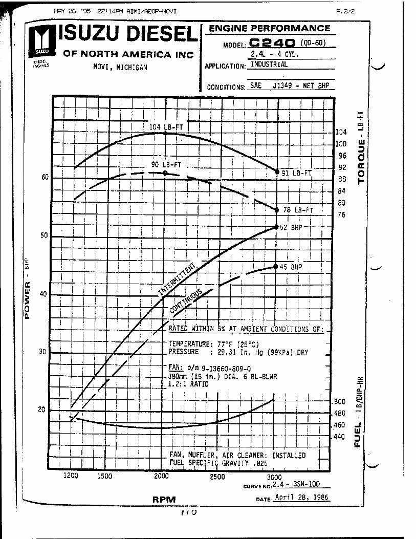
MPY 26 '95 02:14PM AIMI/AEOP-NOVI P. 2/2
KOINES
ISUZU DIESEL OF NORTH AMERICA IIMC
NOVI, MICHIGAN
ENGINE PERFORMANCE
MODEL: C24Q (QD-60) 2.4L - 4 CYL.
APPLICATION: INDUSTRIAL
CONDITIONS: SAE J13A9 - NET BHP
^
^^
tto

Appendix J
///
!
JUL 1 •94 3:24 =P<SE . 001
DETROIT DIESEL eow*oR*noN
FACSIMILE TRANSMISSION ©
FROM: Mike Brogan - Vice President, Generator Sot Power
Phone: (31^92-6709 PAX: (31&yS92-S16$
Number of Pages (Including this one): S" DATE: w3°/?K
TO: /ir^ ^M+/?<ZO FAX: ( ?& jl 3<S/-<Q/<S9
RE: ~p.g7gc»r &t*3&- 1S-7/
*&u/crt 77KT *0¥S~C /S ^TiU. S&hfj
A/OJ £&=G£T*HT M A *io3gi iO*3~7QQ$. TTf-iS
IS A t4ATV&*>*-<Y As/OfKA*Jb ü&t&**r ßi&f*l.
JZa&e* 1( £tJ*it*r hi cu.«y/. ^ufi/C^j
JrouJeaL COM* i s/tecjeteAnotJs ÄrtifcH^ 4
As A *U**J(*W<je&!L doc or*./ \&uj TO
^bflfrft/raff And ßetost*^ QßwwK £&ikt/n«&Jr
M*tjJ&tcri&€&S (Ctertl) . FcQ. /=uCQi**:
<JöU ^THeJU c&sxficr <$&ie cJ/^t^C /&-
C^~OJT&TC MA */ fcU&SAf Ccr up «/co&tyl
WWdHeadquflnar8-13<00(>ÄC>tw,W««/DelfoilMJchig^^^
An Bqurt Opportunity Employer
¥ CYA«***^
&&A-
ihtf=*
J^^sAcc^gu<) ? DM
uz
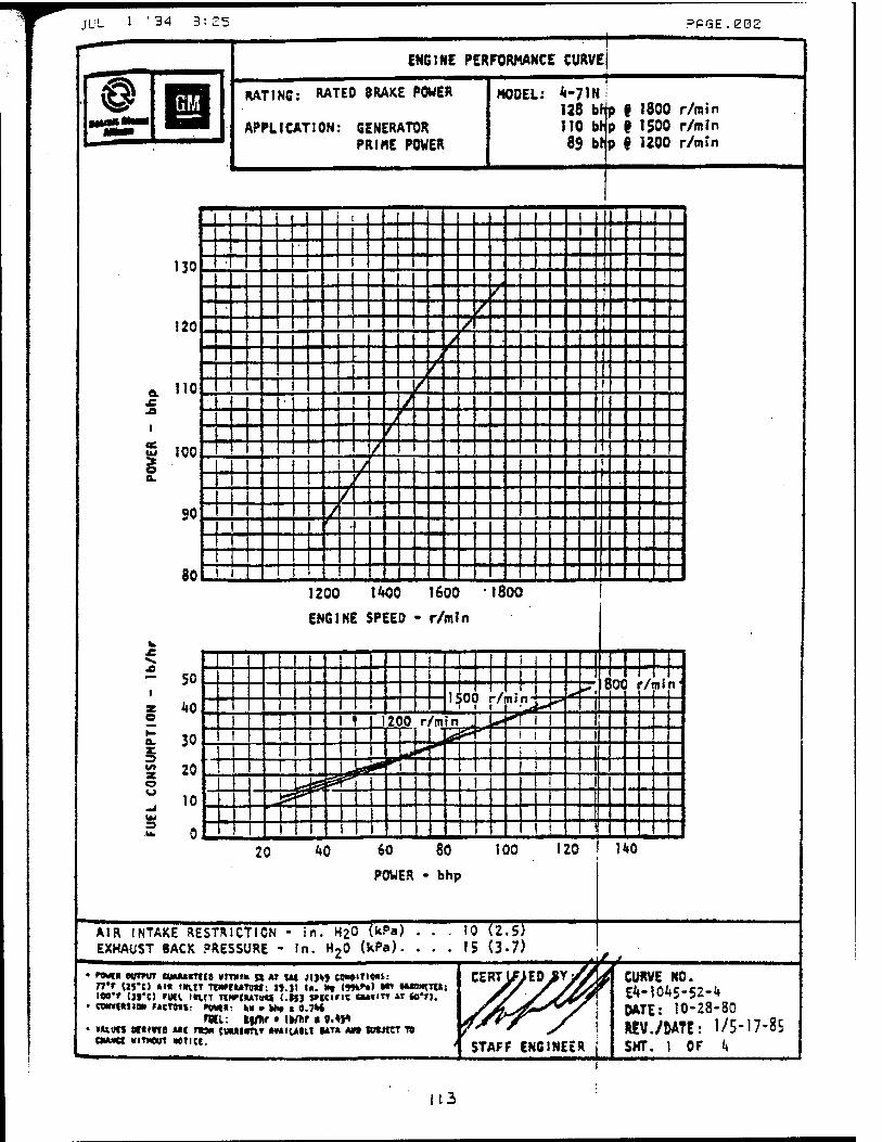
JUL 1 '34 3:2 = .^PGE.eOS
ENGINE PERFORMANCE CURVEj
RATING: RATED BRAKE POWER
APPLICATION: GENERATOR PRIME POWER
MODEL: <I"71N i 128 bfjp i 1800 r/m in !T0 Mp 9 1500 r/mln 83 Mp § 1200 r/min
i
ec
III ,
~P" no '■ — ^^ , ' _.Jl ^^^„^ I
-" ■ ""1 — / " ' : — ± _ _~ z_ __ _ j _ I« -; ~ i > ,. .,j._. 2 : L : ~ z _^-L . ± . „ — :_ : _ _ ./_- X— .. _
110. / __' I _..
uz: —ZZ-JZ^Z I.. : :: " — ^ —
100, J / ,„ , t, . . II / T ■
/ ,:± _ —7 : : go 1 / „ „ — -j f _
~\ 1
80 -J .1,. 1200 1400 1600 1800
ENGINE SPEED - r/min
AIR INTAKE RESTRICTION - in. H20 Wa) . EXHAUST BACK PRESSURE - In. H20 (Wa)
tO (2,5) 15 (3.7)
• n*t evmrr CUMMUU VITVIB n«ui JIJ*J eowTt««: Tt'r ln*c) »»■ «IH.IT ftunuvnt: n.y 1«. *» u»*t) H» *u»nn»: wr in*«) rgct »nn TWCMTWJ <.uj meine o»»m « «o*n.
• confMiw r«tT9t»- »**«: M'Mti 0.7H rtCl: fcfflir • Ik/Iir ■ «.W
• VAlMS »C«tVfB MC TW* CMMtfftT »Miunt •**» «M »URT TS CMUCt WITMOtTT MTICI.
CURVE NO. E4-10A5-52-'» DATE: 10-28-80 WV./DATE: 1/5-17-85 SHT. 1 OF it
113
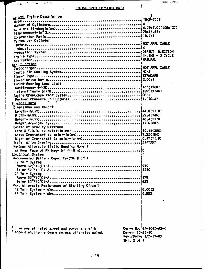
ILL ' 34 »PGE.CG;
ENGINE SPECIFICATION DATA
i0tf\ Pro In« Description Model Number o* Cyltndors gore and Stroke?in(mm).... Displacement-In (L) Compression Ratio Valves p*r Cylinder
*
intake. Exhaust,
Combustion System« Engine Type. Aspiration,
ß?nffPuratron
Turbocharger Charge Atr Cooling System.,... Blower Type , Blower Drive Ratio Thrust 8eer?ng Load Limit Contlnuous-lbf(N) , Intermittent-1 bf(N) ,
Eng ine Crankcese Vent System.. Maximum Pressure-In H.0(kPa}.
Dissensions and Height Langt h-InOnm} • wldth-tndmi) Helght-ln(mm) Kelght,dry-lb(kg),..,........
Center of Gravity 01stance From R.F.0.8. (x exls)-ln(mm) Above Crankshaft (y ax Is)-In(mm) Right of Crankshaft (* axls)-ln(mm).... Instal(atIon Drawing. Maximum Allowable Static Bending Moment at Rear Face of FW Hsg-Ibf ft(N in)
Siwtrfcaf f?y«?t«n _ Recommended Battery Capacity(CCA f 0 F)
12 Yolt Svstem Above 32°F(0°C)-A
104J-7005 4 4.25x5.00(108x127) 284(4.66) 18.7:1
NOT APPLICABLE 4 DIRECT INJECTION INLINE - Z CYCLE NATURAL
NOT APPLICABLE NONE STAN0ARO 2.00x1
400(1780) 1200(5340) OPEN 1.9(0.47)
44.0(1118) 29.4(746) 46.4(1178) 1780(807)
10.14(238) 7.25(184) 0.47(11.9) 3147357
Below 32°F(0°C)-A , 24 Volt Svstem Above 32°F(0®C)-A Below 32°F(CHC>-A
Max, Allowable Resistance of Starting Circuit 12 Volt System - oho 24 Volt System - ohm
950 1250
475 625
0.0012 0.002
*'• values at rated speed and power and with s*an<jard engine hardware unless otherwise noted.
Curve No. Dates- 10- Rev./Date: Sht. 2 of
E4-1045-52-4 28-80
1/5-17-85 4
n4
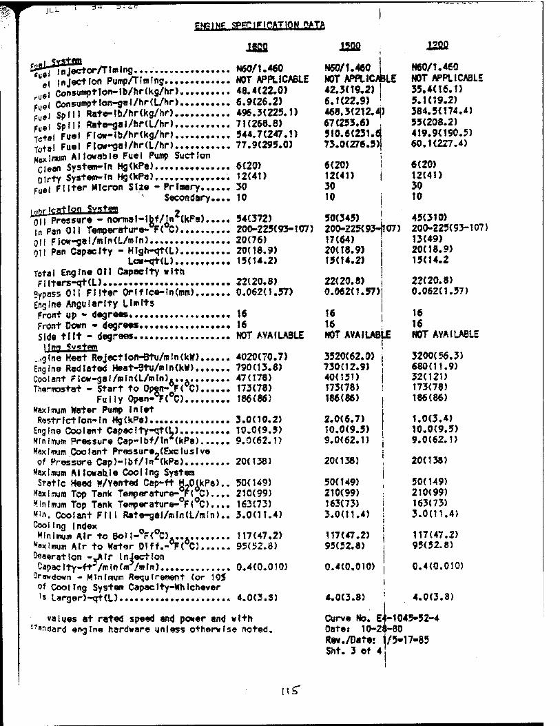
ILL
tTNElNP SPECIFICATION PATA
r9****«««f*
I •*••«* <
♦ • # ♦ ♦ ♦
el inject Ion Pump/TImlng rUel Consumptlon-lb/hr(kg/hr) fuel ConsumptIon-gol/hr(L/Hr) Fuel Split Rate-tb/hr(kg/hr) Fuel $PMI Rate-gal/hr(L/hr), Tc+al Fuel Flow-lb/hr(kg/hr> . Total Fuel Ftow-gal/hr(L/hr)......... Maxima« Allowable Fuel Pump Suction Clean System-In Hg(kPa) . Olrty System-ln Hg(kPa)».
Fuel filter Micron Size - Primary.... Secondary.•
i»arjfffltT9ff SYfftan 2 Oil Pressure - norme MbfAhrtoPa)... In Pan Oil Temperature- F< C) Oil Plow-gal/mln(L/mJn) Oil Pan Capacity - Hlgh-qt(L)
Iflvqta) .♦.. Total Engine Oil Capacity with Filters-qt(L)
Bypass OH Filter OH flee-In (mm) Engine Angularity Limits Front up - degrees...... Front Down - degrees Side tilt - degrees
_.,gfne Heat RejectIon-Btu/mtn(kW).... Engfn« Radiated Heat-9tu/aln(kW) Coolant f low-gal/mIn(L/mln).... Thermostat - Start to Opwi-Jr< C)....
Fully Open-FrC) Maximum Water Pump Inlet Restrict Ion-in Hg(kPa)
Engine Coolant Capecfty-qt(L) Minimum Pressure Cap-lbf/ln (kPa)... Maximum Coolant Pressure (Exclusive of Pressure Cap)-lbf/ln*(kPe),
N60/1.460 NOT APPLICABLE 48.4(22.0) 6.9(26.2) 496.3(225.1) 71(268.8) 544.7(247.1) 77.9(295.0)
6(20) 12(41) 30 10
54(372) 200-225(93-107) 20(76) 20(18.9) 15(14.2)
22(20.8) 0.062(1.57)
16 16 NOT AVAILABLE
4020(70.7) 790(13.8) 47(178) 173(78) 186(86}
3.0(10.25 10.0(9,5) 9.0(62.1)
Maximum Al lowabje Cool Ing System Static Heed w/Yented Cep-ft HJHkPa)..
Maximum Top Tank Temper a ture-°FrCh... Minimum Top Tank Temperature- F< C).... M'n. Coolant Fill Rate-gaI/mIn(L/m!n).. Cooifng Index
Minimum Air to Bof I-rCC).... •tax I mum Air to Water 0?ff.-°F(°C) D«a«ratlon -_AIr Injection Capaclty-ft /mln(m /mln)
Oravdown - Minimum Requirement (or 105 o* Cooling System Cepaelty-Whlchever 's Largar)-qt(L)
20(138)
50(149) 210(99) 163(73) 3.0(11.4)
117(47.2) 95(52.8)
0.4(0.010)
4.0(3.8)
values at rated speed and power and with st»idard engine hardware unless otherwise noted.
lSJfl
N60/1.460 I NOT APPLICABLE 42.5(19.2) ! 6.1(22.9) !
468.3(212. 4J) 67(253.6) 310.6(231.6 73.0(276.5)
6(20) i 12(41) j 30 10 |
50(345) 200-225(93-1107) 17(64) 20(18.9) 15(14.2)
22(20.8) 0.062(1.57)j
! 16 ! NOT AVAILABLE
3520(62.0) I 730(12.9) ] 40(151) 173(78) 186(86) i
2.0(6.7) 10.0(9.5) 9.0(62.1)
20(138)
50(149) 210(99) 163(73) 3.0(11.4)
117(47.2) 95(52.8)
0.4(0.010)
4.0(3.8)
J2C2
N60/1.460 NOT APPLICABLE 35.4(16.1) 5.1(19.2) 384.5(174.4) 55(208.2) 419.9(190.5) 60.1(227.4)
6(20) 12(41) 30 10
45(310) 200-225(93-107) 13(49) 20(18.9) 15(14.2
22(20.8) 0.062(1.57)
16 16 NOT AVAILABLE
3200(56.3) 680(11.9) 32(121) 173(78) 186(86)
1.0(3.4) 10.0(9.5) 9.0(62.1)
20(138)
50(149) 210(99) 163(73) 3.0(11.4)
117(47.2) 95(52.8)
0.4(0.010)
4.0(3.8)
Curve No. E4-1045-52-4 Date: 10-28-80 Rev./Dater /5-17-85 Sht. 3 of 4
lib

jut- 1 J4 I.e. ft«lMg SPgClFtr-ATlON DATA
JjrfS?AI !«■*!• Temperature Rise ^Nit AIP to Engine tnl«t)-"FC «... Klntaka Restriction Max!««» Limit Anir+J Air CU«n^ln H^kPa) ? MR Mr Cleaner-la HjXkea) *!£ Mr Flo« - ft3/m?n<m3/mln) [JE. AlP Box/Manifold Pressure-
Ri2o2w^^' Intaka'pl pe*DIa.-in(B»m)....
«gÖÄfiWßj.» c«haust Temperature- Fi^J JSlwim Allowable Back Pressure-
tn Ha(KPa)..«. ••• ....♦•••♦ R*camended Exhaust Pipe Dlemeter $!ngla-ln(mm)..».» Dual»InCaw>««« .♦.*•••••••••••-•• •
PerffiCSanfiS Power Output-bhp(kW)... Foil load Saeed-r/mln ♦ BfCP-lbf/M (kPa)...., Piston Spaad-ft/mfn(wVmln) Friction Power-bhp(kW)...... Altltuda Capab11lty-ft(m) Noise - d8(A) ff tm... ••••• Sooke -. Bosch Number,.... •
Pnrt I ft** p"wt fionstm°tton
Fu«l-lb/hr(kg/hr) - 0$ Power..... 25$ Power......•♦•• 5« Power 75$ Power 100$ Power
30(16.7)
25(6.2) 13.4(3.3) 380(10.8)
7.5(25.3) 5.0(127)
910(25.3) 820(438)
3.3(11.2)
3.5(89) NOT APPLICABLE
128(95) 1800 99.1(684) 1500(457) 29(22) 16000(4880) 99.7 1.7
8.5(3.9) 16.3(7.4) 25.5(11.6) 35.8(16.2) 48.4(22.0)
FmUsfftnS - 0$
mi 120
C0A 83 HC 50 SO, 39
|ons - 0$
NO 100 C0X 78 HC 41 SO,
ltn\h 29
[qps - 0$
NO 81 CO* 71 HC 33 SO- 23
gm/hr (at 25$ 420 44 48 74
gm/hr iat 25$ 410 36 39 60
gm/hr (at 23$ 580
30 31 46
percent load) 50$ 75$ 790
41 46
116
1300 116
47 162
percent load) 50$ 75$ 770
33 38 98
1230 71 39
140 percent load) 50$ 75$ 720
25 30 80
1100 36 31
115
- 1800 r/wln 100$ 1470 1366
50 220
- 1500 r/mln 100$ 1350 1410
42 190
- 1200 r/nln 100$ 1190 1370
35 160
All values at rated speed and power and with standard engine hardware unless otherwise noted.
30(16.7)
18(4.5) 11(2.7) 320(9.1)
5.0(16.9) 5.0(127)
760(21.5) 810(432)
2.3(7.8)
3.5(89) NOT APPLICABLE
110(82) 1500 102.6C707) 1250(381) 22(16) 14000(4270) 98.2 0.9
6.5(2.9) 13.3(6.0) 21.5(9.8) 31.0(14,1) 42.3(19.2)
Curve No. Date: 1 Rev./Date: $ht. 4 Of
12QQ
30(16.7)
12(3.0) 8.5(2.1) 260(7.4)
2.8(9.5) 5.0(127)
610(17.3) 785(418)
1.5(5.1)
3.5(89) NOT APPLICABLE
89(66) 1200 103.4(713) 1000(305) 16(12) 12000(3660) 96.9 1.0
5.0(2.3) 10.5(4.8) 17.7(8.0) 25.4(11.5) 35.4(16.1)
■4-1045-52-4 0-28-80
1/5-17-85
** T0TPL =£<■}£. C8^

Appendix K
117
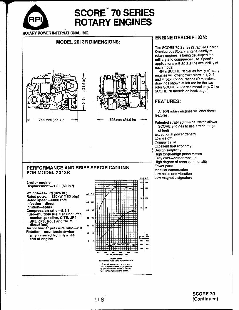
SCORE™ 70 SERIES ROTARY ENGINES
ROTARY POWER INTERNATIONAL, INC.
MODEL 2013R DIMENSIONS:
744 mm (29.3 in)
in
(O
633 mm (24.9 in) —"■
PERFORMANCE AND BRIEF SPECIFICATIONS FOR MODEL 2013R
2-rotor engine Displacement—1.3L (80 in.3)
Weight—147 kg (325 lb.) Rated power—120kW (160 bhp) Rated speed—6000 rpm Injection—direct Ignition—spark Compression ratio—8.5:1 Fuel—multiple fuel use (includes
combat gasoline, CITE, JP4, JP5, JP8, No. 1 and No. 2 diesel fuel)
Turbocharger pressure ratio—2.0 Rotation—counterclockwise
when viewed from flywheel end of engine
Nm lb-«
| 1 | 244
203
13S
68
180
TORQU 150
kW BHP
200
160
120
80
40
0
100
50
119
•PC* VER-
30 lb/
hph * 365
304
243
.800
- FUB L CONSUMPTION » .500
.400
1 DOC 20 00 3008 40 00 sc no K K»
HOOGL2013R ESTIMATED FUU. LOAD PERFORMANCE
'For multi-TOlorversions, power and torque increase in proportion to the number of rotors. Specific fuel consumption is the same.
ENGINE DESCRIPTION:
The SCORE 70 Series (Stratified Charge Omnivorous Rotary Engine) family of rotary engines is being developed for military and commercial use. Specific applications will dictate the availability of each model.
RPI's SCORE 70 Series family of rotary engines will offer power sizes in 1, 2, 3 and 4 rotor configurations (Dimensional drawings shown at left are for the two- rotor SCORE 70 Series model only. Other SCORE 70 models on back page.)
FEATURES:
All RPI rotary engines will offer these features:
Patented stratified charge, which allows SCORE engines to use a wide range of fuels
Exceptional power density Low weight Compact size Excellent fuel economy Design simplicity High torque/high performance Easy cold-weather start-up High degree of parts commonality Fewer parts Modular construction Low noise and vibration Low magnetic signature
we SCORE 70 (Continued)
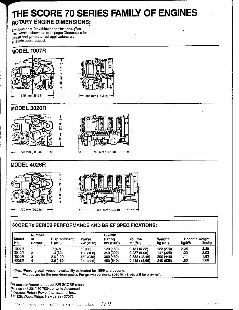
THE SCORE 70 SERIES FAMILY OF ENGINES ROTARY ENGINE DIMENSIONS: Envelope only, for vehicular applications. (Two- rotor version shown on front page) Dimensions for aircraft and generator set applications are available upon request.
MODEL 1007R
648 mm (25.5 in) -»- 465 mm (18.3 in) -*■
MODEL 3020R
MODEL 4026R
898 mm (35.4 in)
SCORE 70 SERIES PERFORMANCE AND BRIEF SPECIFICATIONS:
Model No.
Number of Rotors
Displacement L(in.3)
Power kW (BHP)
Growth1
Rating kW (BHP)
Volume m3 (ft.3)
Weight kg (lb.)
Specific Weight2
kg/kW lbs/hp
1007R 2013R 3020R 4026R
1 2 3 4
.7(40) 1.3(80) 2.0(120) 2.6(160)
60 (80) 120(160) 180(240) 240 (320)
120(160) 240 (320) 360 (480) 480 (640)
0.151 (5.32) 0.257 (9.08) 0.353(12.46) 0.415(14.65)
123(270) 147(325) 200 (440) 240 (530)
2.05 3.38 1.23 2.03 1.11 1.83 1.00 1.66
Notes: 'Power growth version availability estimated for 1995 and beyond. 2Values are for the near-term power. For growth versions, specific values will be one-half.
por more information about RPI SCORE rotary engines call 201/470-7004, or write Advanced Programs, Rotary Power International Inc., Box 128, Wood-Ridge, New Jersey 07075.
n 9
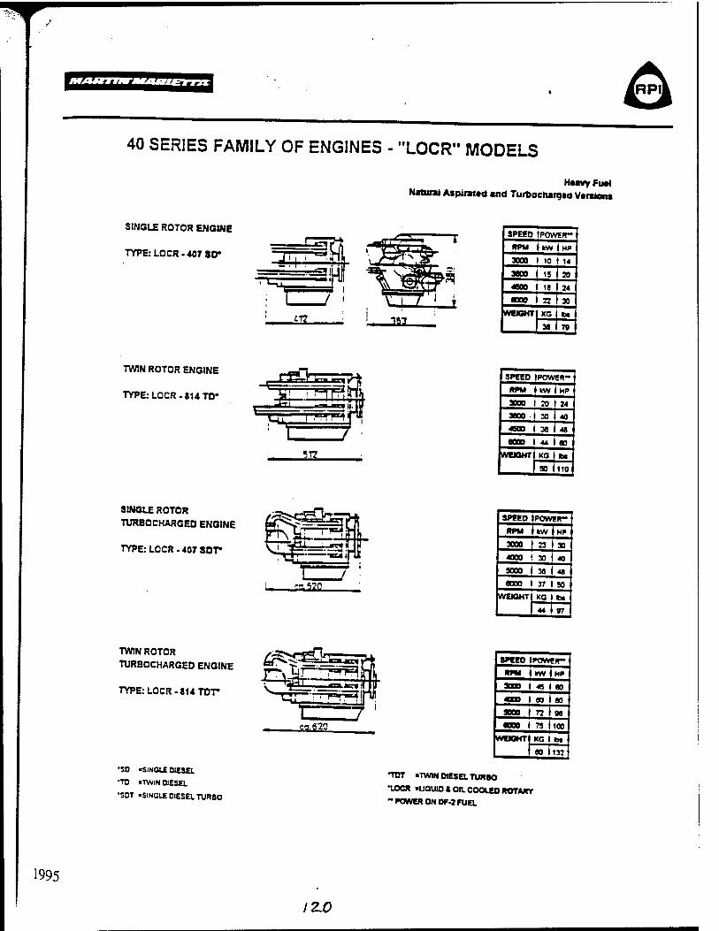
1995
40 SERIES FAMILY OF ENGINES - "LOCR" MODELS
Heavy Fual Natural Aspirated and Turbochargad Varsiens
SINGLE ROTOR ENGINE
TYPE: LOCR-407 3D»
SPEEO IPOWER-
RPM t kW I HP
3000 1 10 t 14
3000 1 15 I 20
«00 | 18 I 24
aooo ( a i M WEIGHT KG i la
36 I 79
TWIN ROTOR ENGINE
TYPE: LOCR-814 TO*
ST?
SPEED IPOWER-
RPM ( kW I HP
3000 I 20 I 24
3BO0 I 30 I 40
4800 I 38 I 48
6000 I 44 I 80
WEIGHT) KG t»
I 50 110
SINGLE ROTOR
TURBOCHARGEO ENGINE
TYPE: LOCR - 407 SOT»
SPEED IPOWER-
RPM i UVV I HP
3000 I 23 I 30
4000 ( 30 t 40
5000 1 38 i 48
6000 t 37 I SO
WEIGHT) KG I ta
44 I 07
TWIN ROTOR
TURBOCHARGEO ENGINE
TYPE: LOCR. 814 TOT*
'SO 'SINGLE OIESEL
•TO «TWIN OIESEL
•SOT «SINGLE OIESEL TURBO
SPEED IPOWER-
RPM i kW ♦ HP
3000 1 45 I 80
4000 1 60 1 80
SOOO I 72 (98
•000 1 75 1100
WEIGHT KG 1 t»
80 i132
TDT «TWIN OIESEL TURBO
•LOCR ■UQUIO 4 OIL COOLED ROTARY - POWER ON OF-J FUEL
12J0
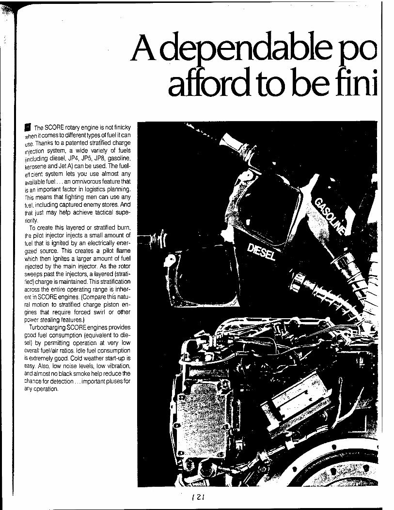
A dependable po afford to be nni
| The SCORE rotary engine is not finicky when it comes to different types of fuel it can use. Thanks to a patented stratified charge injection system, a wide variety of fuels (including diesel, JP4, JP5, JP8, gasoline, kerosene and Jet A) can be used. The fuel- efficient system lets you use almost any available fuel... an omnivorous feature that is an important factor in logistics planning. This means that fighting men can use any fuel, including captured enemy stores. And that just may help achieve tactical supe- riority.
To create this layered or stratified burn, the pilot injector injects a small amount of fuel that is ignited by an electrically ener- gized source. This creates a pilot flame which then ignites a larger amount of fuel injected by the main injector. As the rotor sweeps past the injectors, a layered (strati- fied) charge is maintained. This stratification across the entire operating range is inher- ent in SCORE engines. (Compare this natu- ral motion to stratified charge piston en- gines that require forced swirl or other power stealing features.)
Turbocharging SCORE engines provides good fuel consumption (equivalent to die- sel) by permitting operation at very low overall fuel/air ratios. Idle fuel consumption is extremely good. Cold weather start-up is easy. Also, low noise levels, low vibration, and almost no black smoke help reduce the chance for detection... important pluses for any operation.
\Z\
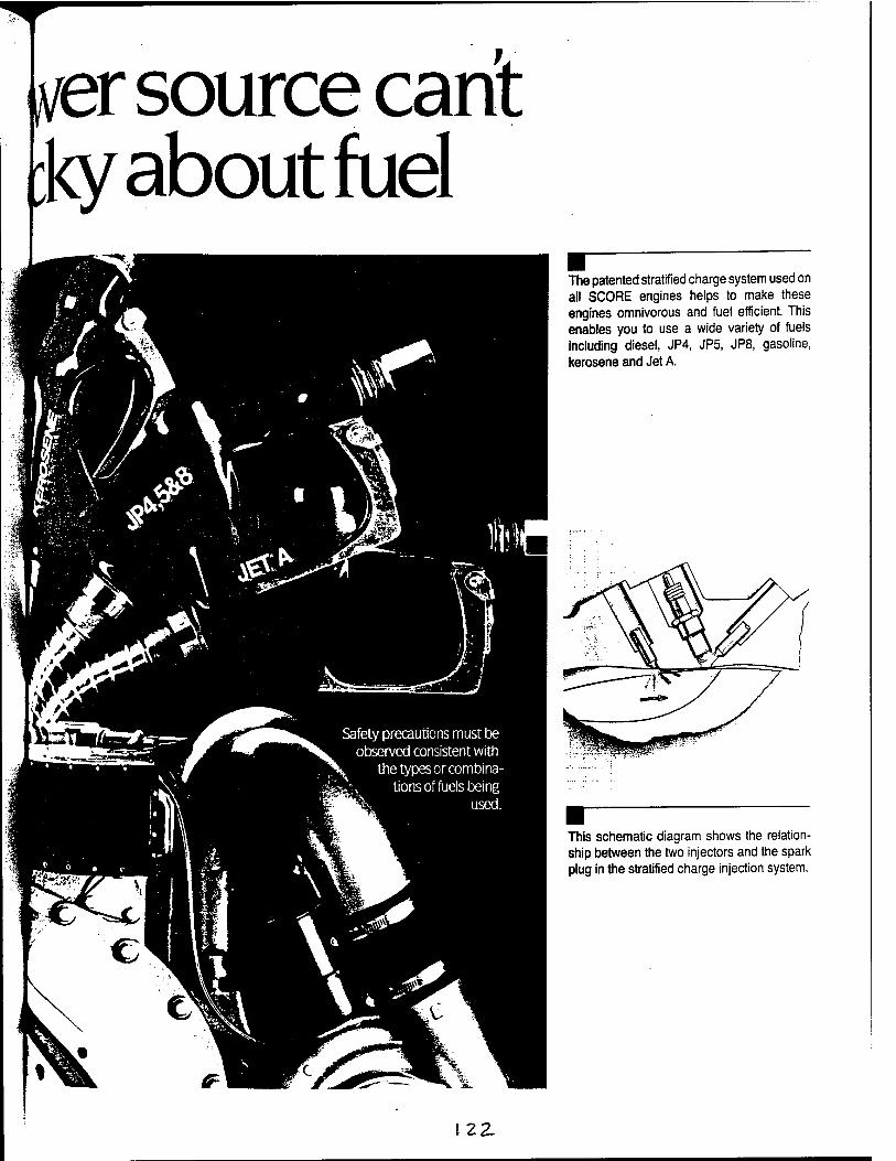
nfer source cant :ky about fuel
The patented stratified charge system used on all SCORE engines helps to make these engines omnivorous and fuel efficient. This enables you to use a wide variety of fuels including diesel, JP4, JP5, JP8, gasoline, kerosene and Jet A.
This schematic diagram shows the relation- ship between the two injectors and the spark plug in the stratified charge injection system.
122-
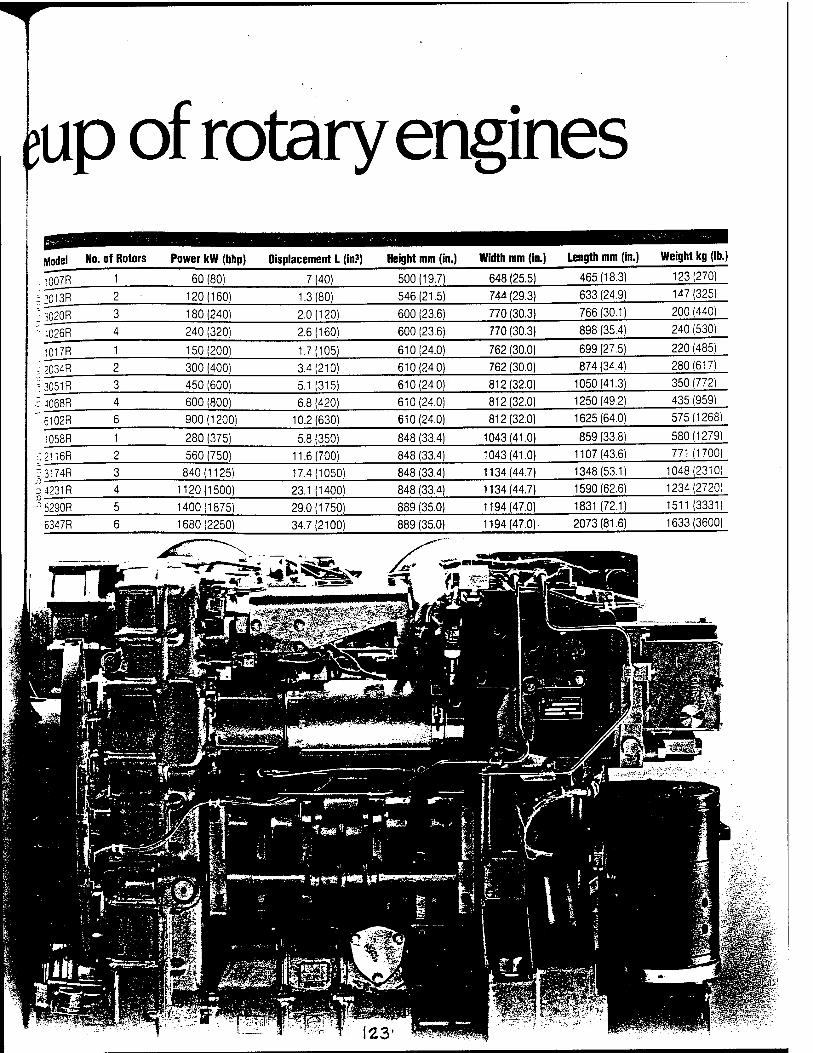
up of rotary engines
:,•'-; ?•=•'-4«'v-«"'."-.-;
;i013R 2 120(160) 1.3(80) 546(21.5) 744 (29.3) 633 (24.9) 147(325)
: 3020R 3 180(240) 2.0(120) 600 (23.6) 770 (30.3) 766(30.1) 200 (440)
- -1026R 4 240 (320) 2.6(160) 600 (23.6) 770 (30.3) 898 (35.4) 240 (530)
1017R 1 150(200) 1.7(105) 610(24.0) 762 (30.0) 699 (27.5) 220 (485)
- 2034R 2 300 (400) 3.4(210) 610(24.0) 762 (30.0) 874 (34.4) 280(617)
-^ 3051R 3 450 (600) 5.1 (315) 610(24.0) 812(32.0) 1050(41.3) 350 (772)
■t 4068R 4 600 (800) 6.8 (420) 610(24.0) 812(32.0) 1250(49.2) 435 (959)
6102R 6 900(1200) 10.2(630) 610(24.0) 812(32.0) 1625(64.0) 575(1268)
1058R 1 280 (375) 5.8 (350) 848 (33.4) 1043(41.0) 859 (33.8) 580(1279)
.1 2116R 2 560 (750) 11.6(700) 848 (33.4) 1043(41.0) 1107(43.6) 771 (1700)
5 3174R 3 840(1125) 17.4(1050) 848 (33.4) 1134(44.7) 1348(531) 1048(2310)
2 4231R 4 1120(1500) 23.1 (1400) 848 (33.4) 1134(44.7) 1590(62.6) 1234(2720)
-1 5290R 5 1400(1875) 29.0(1750) 889 (35.0) 1194(47.0) 1831(72.1) 1511 (3331)
6347R 6 1680(2250) 34.7(2100) 889 (35.0) 1194(47.0)- 2073(81.6) 1633(3600)
•/lv I I -""V ■^■■V
\ '-/ 'TI'%' ~ »% ■■" lot? i— ■ -. a.—-> 1 fe
* J
;• ihntTiririjiTi ---—aaaaäüj «egg
ml*
'■ ■
s? i *■•;_,v-1
1 E> ■&
j ^ £
^,:.-a''!M *i
^fSä f**» I«'
£ife^*:! *!
-v-.-ySfsSv;
HSPT l£3«glB£
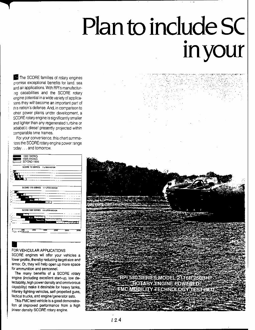
T
Plan to include SC in your
The SCORE families of rotary engines promise exceptional benefits for land, sea and air applications. With RPI's manufactur- ing capabilities and the SCORE rotary engine potential in a wide variety of applica- tions they will become an important part of this nation's defense. And, in comparison to other power plants under development, a SCORE rotary engine is significantly smaller and lighter than any regenerated turbine or adiabatic diesel presently projected within comparable time frames.
For your convenience, this chart summa- rizes the SCORE rotary engine power range today... and tomorrow.
^■i 1992 RATING i^H 1995 RATING I I BEYOND 1995
SCORE 70 SERIES 7 UTER/ROTOR
SCORE 170 SERIES 1.7 UTER/ROTOR
SCORE 580 SERIES 5 S UTER/ROTOR
? 555 iööö i55B 3555 iSScT r-^SE HORSEPOWFR
FOR VEHICULAR APPLICATIONS SCORE engines wil offer your vehicles a lower profile, thereby reducing target size and armor. Or, they will help open up more space for ammunition and personnel.
The many benefits of a SCORE rotary engine (including excellent start-up, low de- tectability, high power density and omnivorous capability) make it desirable for heavy tanks, infantry fighting vehicles, self-propelled guns, tactical trucks, and engine/generator sets.
This FMC test vehicle is a good demonstra- tion of improved performance from a high power density SCORE rotary engine.
•'-*•■*.' 2-~
IZA
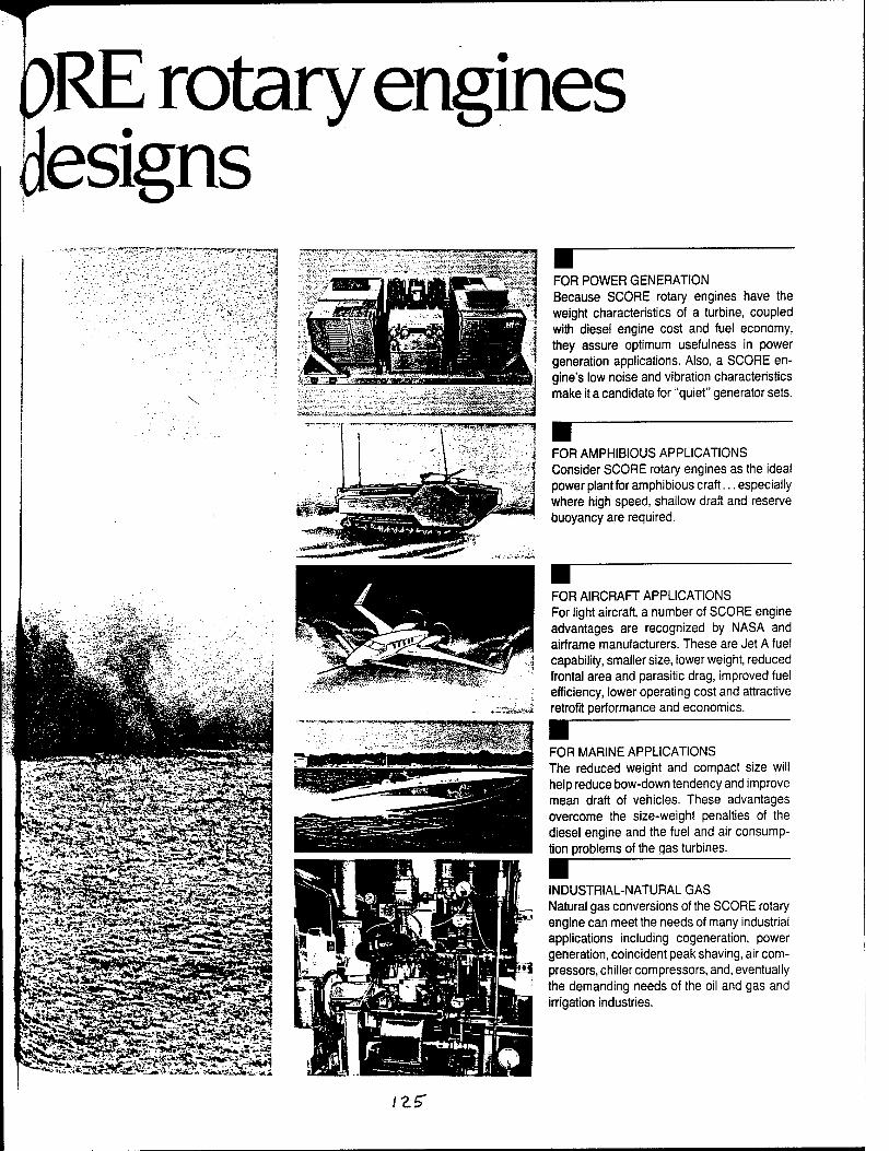
ORE rotary engines designs
FOR POWER GENERATION Because SCORE rotary engines have the weight characteristics of a turbine, coupled with diesel engine cost and fuel economy, they assure optimum usefulness in power generation applications. Also, a SCORE en- gine's low noise and vibration characteristics make it a candidate for "quiet" generator sets.
FOR AMPHIBIOUS APPLICATIONS Consider SCORE rotary engines as the ideal power plant for amphibious craft... especially where high speed, shallow draft and reserve buoyancy are required.
FOR AIRCRAFT APPLICATIONS For light aircraft, a number of SCORE engine advantages are recognized by NASA and airframe manufacturers. These are Jet A fuel capability, smaller size, lower weight, reduced frontal area and parasitic drag, improved fuel efficiency, lower operating cost and attractive retrofit performance and economics.
■ FOR MARINE APPLICATIONS The reduced weight and compact size will help reduce bow-down tendency and improve mean draft of vehicles. These advantages overcome the size-weight penalties of the diesel engine and the fuel and air consump- tion problems of the qas turbines. ■ : INDUSTRIAL-NATURAL GAS Natural gas conversions of the SCORE rotary engine can meet the needs of many industrial applications including cogeneration, power generation, coincident peak shaving, air com- pressors, chiller compressors, and, eventually the demanding needs of the oil and gas and irrigation industries.
/Z£T

Appendix L
iZS
w c ——^ "*■■<
f <*—~ G*
w P 3 < 00
3
$'
&&
I D9^
1^ Q. <0
tn
in UJ
U
a z
*-i Q %
en
o 60 OJ .2 o D OS
Iß 5 «
en 5j< U äs S- «o
e BJD
a 5 «
en 3 * <? O «5
£f = 35 - a s
-a
'i «2 _ = m ü © <« ° — co
en O
ej c
-Ü « a w b en s e ~~ s
S « CM D -9> C/S ™* w OS ^^ CO —' 00 tr*r CO sn X .-Si 3 i K < ECO •= CO CJ ©
$2 "i is »- 's jo § 3 - Sg ™ oo Sj co c r~ ^3 © "^ © o -H U ■» -a « to °° o o —
r is ■*
U Q s 0
X sc
c ej 3 — ■= eo
CO ■^ ~ <M
O ©J (« ac a ec CO Ma OS
e ^ OS C co te 10 .sR •s. co -5> .3 CO
Q _J BE© in co .3 f
U CO : ao
j> -* DO» U -i _* to a t-- a =? a © <
1> < C <X5
^ £j ^B ; — <C
>-Cf kkl : ■ 'J' " O 7 <£ haHBH4f ?
&>\ r- Ü.
^1 —"^ UJ :
D3H:
|E I OS ' < Z
OL « Ü ■—' >. CO z —
e
i
I
, t '- ^
*
-: y; u cu
V ^: = «- - o c
c C8 s c o "3
<J E ir Ö ID CO
^
ea J !/l ':£ E CJ 3 ft. e >
§ C 5
'5c cr
•— v:
P ' w ? o ~ S w
2- S v; S-. c •s in ?^
JZ CJ _J1 is 'S < »* § *x v;
5T eu
^
\n s <r SJ. f ^—. CO
•— '& GC
LC
v:
"CJ -a CJ T"! p _£ «- r3 —j — r^
QJ
i— cT1 S
C/3
vi CJ
_V5
'r5
CJ i-
2
O
■g
3 <
S
C-O
< CJ CJ
■:= ' »J "r? cj
CJ ^P
i 3J
53
"a
5 in km
2 c Ö c
E c 3
en
>
v:
Ö
3
o
"3 "3c
0) —*•
B
V5 CJ
£
CD
£ t-
E CJ
k_. i; <
CO V]
_CJ
VJ
a 'E
= 1 es
"5. a, < S3
"2
c?5 igiit
wei
ght
mi
umcr
ous
appl
in
C3
_0J
CJ
'x -<
"c
*5
-o c u
c/;
t-2-7
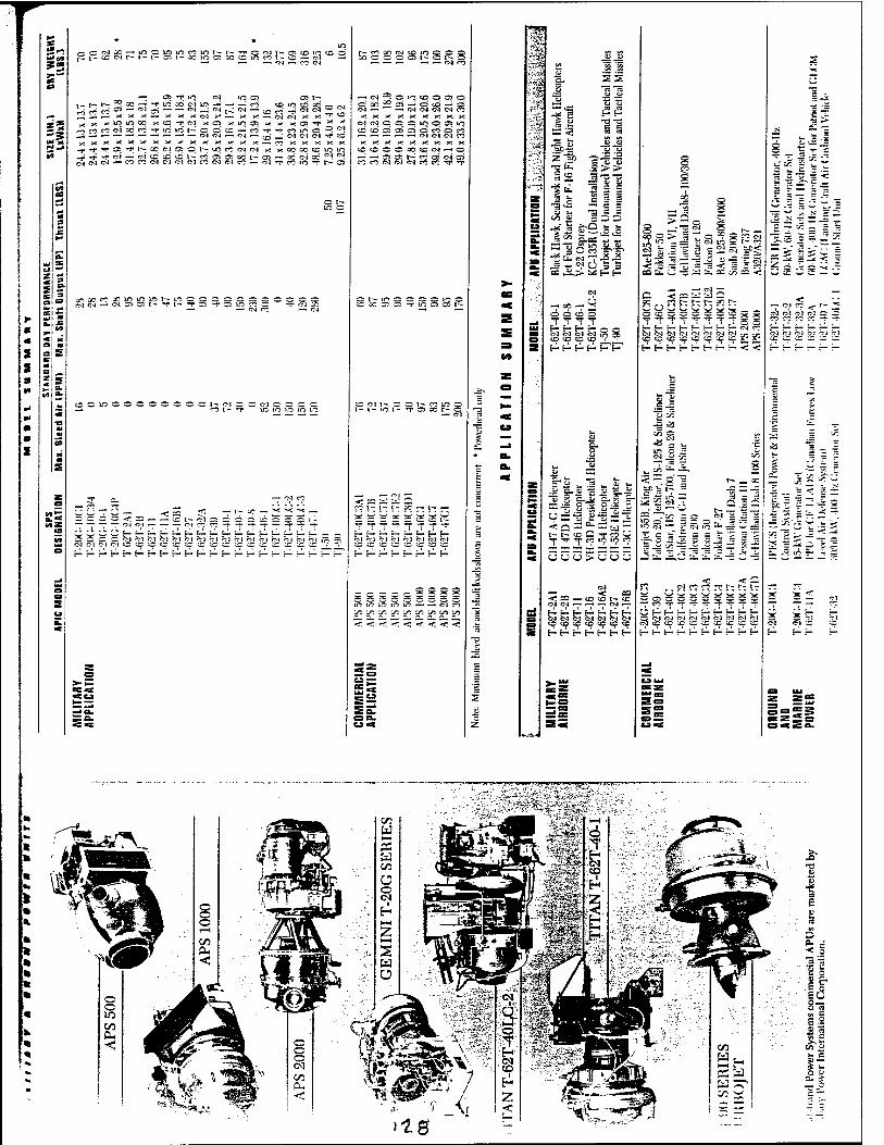
^ •**i/»
•*-i
Is*
-crMX-womiortißt-r*t p i-- <c PI h- i" i" c: i- ac in c; cc c IC « I- C '— PI —
— oi — co CM
•—; s> i"in CM uo en ! =e ~— -v _o" ac PI in —« —• — co i — oi ,-j — — 01 _' CM j^; CM — : : x x — x x x CM x .—. x x ) iWCO x tC T PI xOJ x w a i * « t in 10 r^ c c ffl — « ■
© wdec c^ -: CM CM CM CM X X
X X X X X X X X X X X . : 1- t- X PI O C 1^ CC O C) fM I — Pi tC tC tC t- CO C5 33 CC W _- _____ ■ rtCO'MCM'M(Mnc<l(MC?-(NTnin,TN33
' T CO 1 > —- (M * ■ CO X : x QO c I-Xi
—. °^ X X O PI rr cd X X
_03CC*-_C-Olf!lC-— m Cl <N — C. Ci G- t-- - I-
«I
s 2 0
a S — I
SI. *!=■
r (4 '
Nwxojcomccc coooocnr-cci-o _ __. _-, _-, __4 CM co
-<N^C-3CD0050 Gcd52_J-—-OCO^-CS OJ—."* — CM PI PI PI CO XXXXXXXX.X NMCCO-J005W
:xxxxxxxx iCCCXtCMHC ' — C! 3) I-" C5 OS M O) i c? CM PI PI co co rr *r
X PI I- C C W « ifl O I-i- ICI- TO) X--5
— PI
CCCC<_:---_;i-ol3)6c :J oi — — ■
öl CM CM CM CM bi i
■r-E-_-S-r-E-_-_-i
<. cc __: ü- C r? -~ '.~ IT -C - i"; -
;_lt_.t_.j_.i_.f__t_,E__ PI CM PI CM Pi PI PI PI
ir; if? »o no _o — — P4 co '^C' iO '■£"■ '■£"• sP rC* 'IO IO _°
O—- _>■*
t-hf-hhf-
"EL SS .__ 11
-¥ 2 H E- =: Ö = <j « cs
■fi " 0) OJ
Z .=£ c •JS.-5 P ■-a &-
■I<_
>> 1) OJ c c c c
£3 g 3
■_ "H C/3 Ü
£_ (D
:_>__> > k^.'
CU_C
O CO
_. >_ 8 OO in CO
Co
"3 PI
PJ c
3C
ID PI P5 =P5
« __ CM CO c; ■_■_ EU :. — "3 ;J < -= Ä SJ
CQÄ >■ __! _-_- ea u. w ■3 W — _c _o =c <
CM a ■? ^ rr« PI id /-\
( ) or r- "7 —I c;;,; j,,; w
o to ft« »-r T T T T TT "T
f-hhH f- __, hhh f- L- __ PJ CO in as s^ ^ to to CO to tc to tc tc to *V
a 3 i_ .3 t_ 53 _. J H.U s ü _Li_ ^ J f-■! g-j §- «=■_ _•_ = _;
< a s °- _; u — t- r^ _ C -n- c-3 Cj; ^ -^ -<r crj »9 w? e?
ÜÜü>ÜÜÜ
hhf-Hhf-h W W M Dl w w a _ CO CC CC CC CC CC
t~ H H H H f-1- H
E-f-E-r-r-E-r-r-<<:
cu ^ ■ _ =a
"8 _ - w ? £i PI ,__ _o
C i; _ r _|
v; S _ ^
i^ = — -. _^-
W sC w ü= — —
CM PI PI PI C_ O
PJ _Ü _Ö
< "■ SE" a-
ao -7^; = O _ PJ -
"^CM"*- _ ?i K **" __
r- _ =c
t- :
CO <M eo co "T t~- r~-
-7 CO ^? ^f _T ^ _f = _5
C H H E- 0 PI PI PI CM tC tC tC
__________ PI PJ PJ PI PI _; x cc x c
E-E-E-f-r-r-S-r-^-r-
5*5 £ > <-= _ —
ogg3 H«_a.
-
: \1 _ • _
•
•
* •1
E V „
D D. < C
O
a _
.S
1
eu 0
c e CD Is
c C/3 u
* u _J _ t
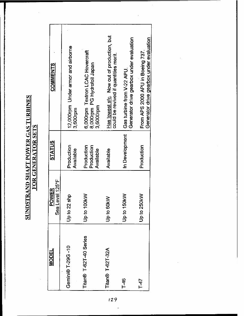
c C g *. *? **3
CD c CD CO c o 3 . 3 i_ o 1—
CD i_ O 1 du
cti
erit.
CO > CD 17
37
eval
(/] CD
Dn L
CA
C H
ovei
yd
rofo
il Ja
pan 2 E i_
CD C CD H Z UJ s s o Ü
c CO 1_ o E i_ CD i_ 0) N
ow o
ut o
f p
1 if q
uant
ities
from
V-2
2 A
PU
. riv
e ge
arbo
x un
d
AP
U i
n B
oeii
gear
box
und
GO ■D C D aO
CD > 00
0 riv
e
Z h- 0- 4—« > CD <D *o CM T3
E _ ^ ^ E CO c k C/D fc 3 D. E E E Q. CD CD 5 5 a! 5 ei o e- xi 3 2 < 5 3 o o o o o ID — CD IS o o o o o to 3
O o CO c
H CM"*0 O O CD CD CO CD 2 0) GO GO T- CO CD" CO CO X ÜÜ uZCD < H
td GO c
a!
o
OS w CD E o 3 c c c Q. c
2 < 1- (0 du
ctio
ila
ble
duct
io
duct
io
ilabl
e CD
XI
O
CD > CD
o ■G 3
H Ed o CO 2 2 5 CD >
Q 2 u. z Ü- < D_ 0. < < c Q.
< Ed
a o GO tf LL Q O o
m Z fa «• CM
5 H GO O
UJ
O > CD
Q. x: V) O
XL O O a. ^ CN o o lO CO
CO CM CD T— CM Z CD O o o o O 3 C/5 *-* -•-* «*-*
Q. Q. Q. Q. Q. 3 D D D D
CO CD 'i_
_J O
CD CO <
UJ ' O CN
Q O T CO i
O 0) CM
1- CM
1- CM
■ä 1-
• © c
CD i
®
«9
® E C c CD r- CD CD CO 1" T CD K H f- K
/29
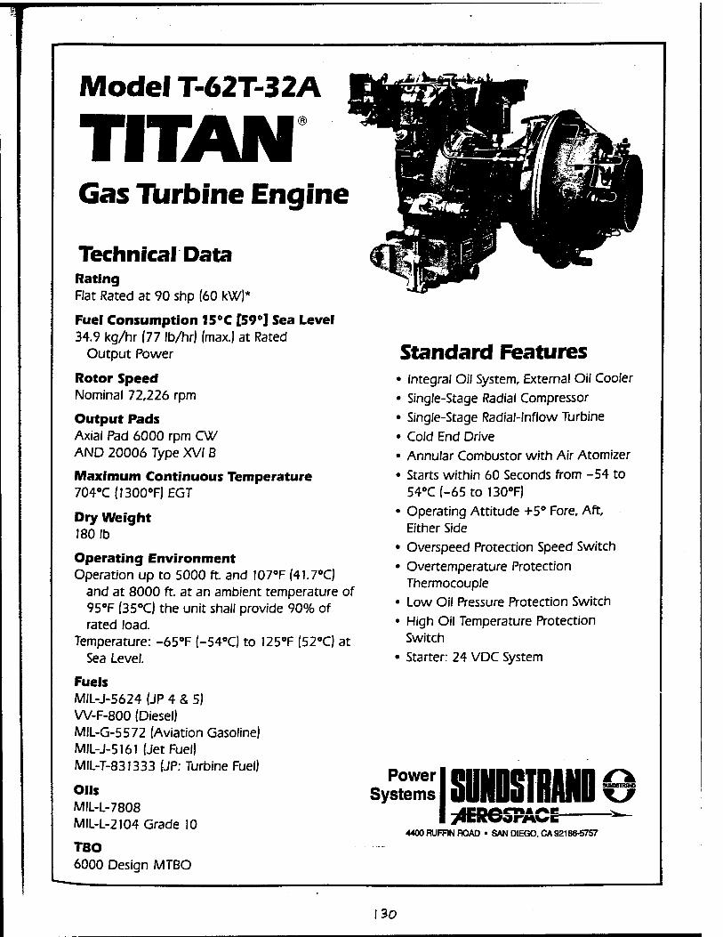
Model T-62T-32A
TITAN Gas Tiirbine Engine
Technical Data Rating Flat Rated at 90 shp (60 kW)*
Fuel Consumption 15°C [59°] Sea Level 34.9 kg/hr (77 lb/hr) (max.) at Rated
Output Power
Rotor Speed Nominal 72,226 rpm
Output Pads Axial Pad 6000 rpm CW AND 20006 Type XVI B
Maximum Continuous Temperature 704°C (1300°F) EGT
Dry Weight 180 1b
Operating Environment Operation up to 5000 ft. and I07°F (41.7°C)
and at 8000 ft. at an ambient temperature of 95°F (35°C) the unit shall provide 90% of rated load.
Temperature: -65°F (-54°C) to I25°F (52°C) at Sea Level.
Fuels MIL-J-5624 (JP 4 & 5) W-F-800 (Diesel) MIL-G-5572 (Aviation Gasoline) MIL-J-5I6I (Jet Fuel) MIL-T-83I333 (JP: Turbine Fuel)
Oils MIL-L-7808 MIL-L-2104 Grade 10
TBO 6000 Design MTBO
Standard Features • Integral Oil System, External Oil Cooler
• Single-Stage Radial Compressor
• Single-Stage Radial-Inflow Turbine
• Cold End Drive • Annular Combustor with Air Atomizer
• Starts within 60 Seconds from -54 to 54°C (-65 to 130°F)
• Operating Attitude +5° Fore, Aft, Either Side
• Overspeed Protection Speed Switch
• Overtemperature Protection Thermocouple
• Low Oil Pressure Protection Switch
• High Oil Temperature Protection Switch
• Starter: 24 VDC System
Power I Systems
I yVEKw< 4400 RUFF1N ROAD • SAN DIEGO. CA 92186-5757
30
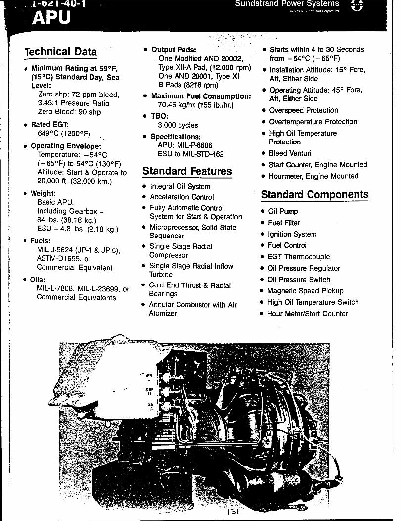
I-0ZI-4U-1
APU ii«TW3»2OTin
Technical Data • Minimum Rating at 59°F,
(15°C) Standard Day, Sea Level:
Zero shp: 72 ppm bleed, 3.45:1 Pressure Ratio Zero Bleed: 90 shp
• Rated EGT: 649°C(1200°F)
• Operating Envelope: Temperature: -54°C (-65oF)to54°C(130°F) Altitude: Start & Operate to 20,000 ft. (32,000 km.)
• Weight: Basic APU, Including Gearbox - 84 lbs. (38.18 kg.) ESU-4.8lbs. (2.18 kg.)
• Fuels: MIL-J-5624 (JP-4 & JP-5), ASTM-D1655, or Commercial Equivalent
• Oils: MIL-L-7808, MIL-L-23699, or Commercial Equivalents
• Output Pads: One Modified AND 20002, Type Xll-A Pad, (12,000 rpm) One AND 20001 .Type XI B Pads (8216 rpm)
• Maximum Fuel Consumption: 70.45 kg/hr. (155 lb./hr.)
• TBO: 3,000 cycles
• Specifications: APU: MIL-P-8686 ESU to MIL-STD-462
Standard Features • Integral Oil System
• Acceleration Control
• Fully Automatic Control System for Start & Operation
• Microprocessor, Solid State Sequencer
• Single Stage Radial Compressor
• Single Stage Radial Inflow Turbine
• Cold End Thrust & Radial Bearings
• Annular Combustor with Air Atomizer
• Starts within 4 to 30 Seconds from -54°C(-65°F)
• Installation Attitude: 15° Fore, Aft, Either Side
• Operating Attitude: 45° Fore, Aft, Ether Side
• Overspeed Protection
• Overtemperature Protection
• High Oil Temperature Protection
• Bleed Venturi
• Start Counter, Engine Mounted
• Hourmeter, Engine Mounted
Standard Components • Oil Pump
• Fuel Filter
• Ignition System
• Fuel Control
• EGT Thermocouple
• Oil Pressure Regulator
• Oil Pressure Switch
• Magnetic Speed Pickup
• High Oil Temperature Switch
• Hour Meter/Start Counter
«i-ii,
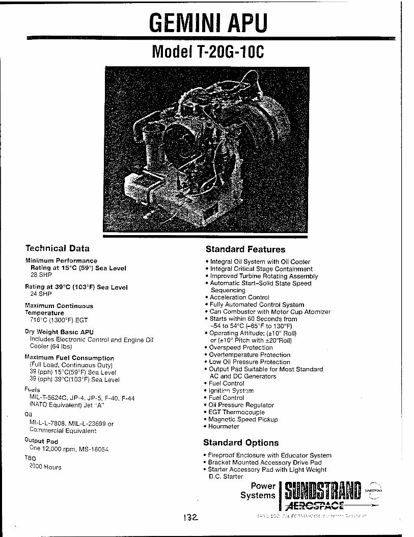
GEMINI APU Model T-20G-10C
Technical Data Minimum Performance
Rating at 15°C (59°) Sea Level 28SHP
Rating at 39°C (103°F) Sea Level 24SHP
Maximum Continuous Temperature
716"C(1300°F)EGT
Dry Weight Basic APU Includes Electronic Control and Engine Oi Cooler (64 lbs)
Maximum Fuel Consumption (Full Load, Continuous Duty) 39 (pph)15°C(59cF) Sea Level 39 (pph) 39oC(103=F) Sea Level
Fuäis MIL-T-5624C. JP-4, JP-5. F-40. F-44 (NATO Equivalent) Jet "A"
Oil
Ml-L-L-7808, MIL-L-23699 or Commercial Equivalent
Output Pad One 12,000 rpm, MS-18054
TBO 2000 Hours
Standard Features • Integral Oil System with Oil Cooler • Integral Critical Stage Containment • Improved Turbine Rotating Assembly • Automatic Start-Solid State Speed
Sequencing • Acceleration Control • Fully Automated Control System • Can Combuster with Motor Cup Atomizer • Starts within 60 Seconds from
-54 to 54°C (-65T to 130°F) • Operating Attitude; (±10° Roll)
or (±10° Pitch with ±20°Roll) • Overspeed Protection • Overtemperature Protection • Low Oil Pressure Protection • Output Pad Suitable for Most Standard
AC and DC Generators • Fuel Control • Ignition System • Fuel Control • Oil Pressure Regulator • EGT Thermocouple • Magnetic Speed Pickup • Hourmeter
Standard Options • Fireproof Enclosure with Educator System • Bracket Mounted Accessory Drive Pad • Starter Accessory Pad with Light Weight
D.C. Starter
Power Systems
T&EROSPA \^Z EGO CALIFORNIA-

Appendix M
/33
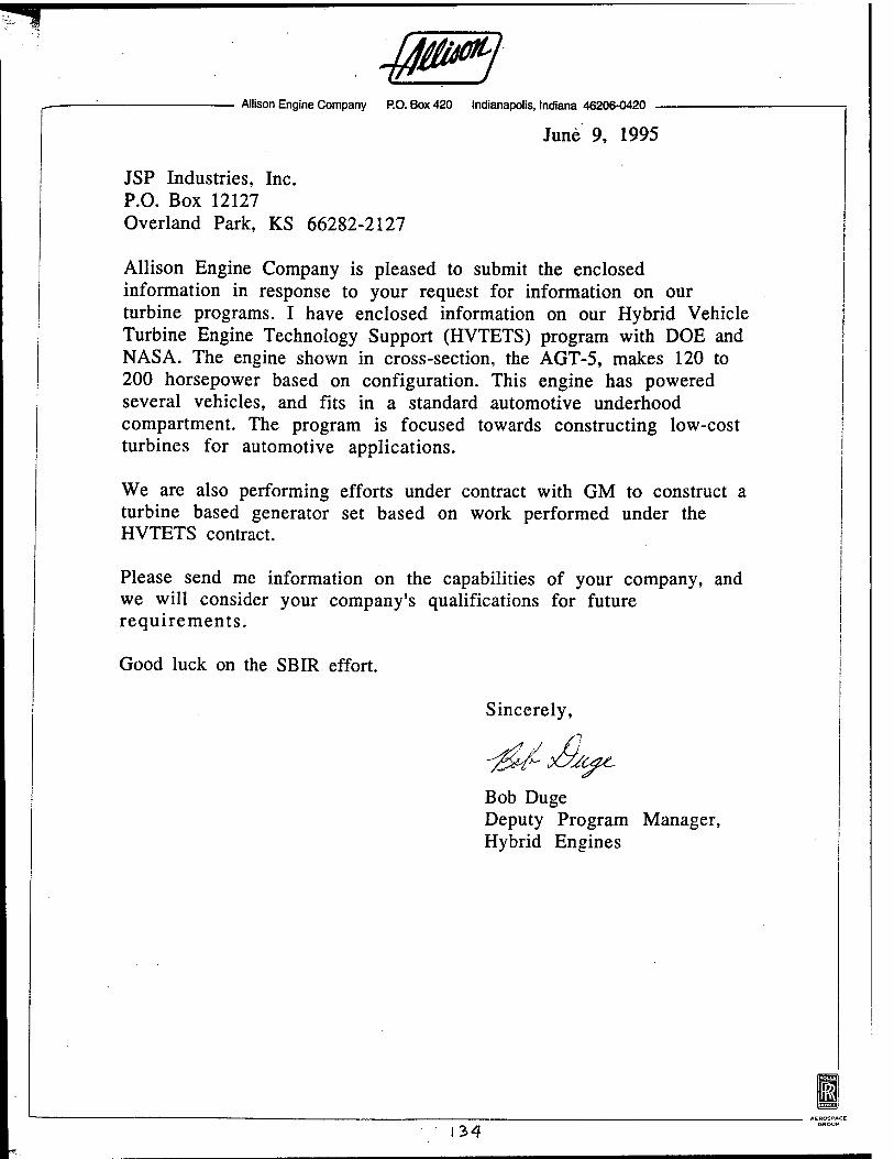
40^ Allison Engine Company P.O. Box 420 Indianapolis, Indiana 46206-0420
June 9, 1995
JSP Industries, Inc. P.O. Box 12127 Overland Park, KS 66282-2127
Allison Engine Company is pleased to submit the enclosed information in response to your request for information on our turbine programs. I have enclosed information on our Hybrid Vehicle Turbine Engine Technology Support (HVTETS) program with DOE and NASA. The engine shown in cross-section, the AGT-5, makes 120 to 200 horsepower based on configuration. This engine has powered several vehicles, and fits in a standard automotive underhood compartment. The program is focused towards constructing low-cost turbines for automotive applications.
We are also performing efforts under contract with GM to construct a turbine based generator set based on work performed under the HVTETS contract.
Please send me information on the capabilities of your company, and we will consider your company's qualifications for future requirements.
Good luck on the SBIR effort.
-gU-dbt
Sincerely,
Bob Duge Deputy Program Manager, Hybrid Engines
m
134
T4I* ca^ bTSg ft '■'' 1^*"*
■J**!»
k^QQ' -03 Pja- Sd 1 H 4^ ■**i-,,.„ * -a
U§Sr ■^13 r^tS >*j IH^L
M-£?S8li: ii5!^s_ij
F^lM ^
r^ ;-LLI>^, "^CS1- -|^J
ee
o> Ü < UJ Q.
oo EC Ü
> w
DC (0 HI ^ III)
\ < 45 v>
■^vüJP^zf&m 3Q:ö±)Sir:
JLZD<X3iüiO

LÜ is WK m jö >- g X
z ü
LU
(/) o m v)
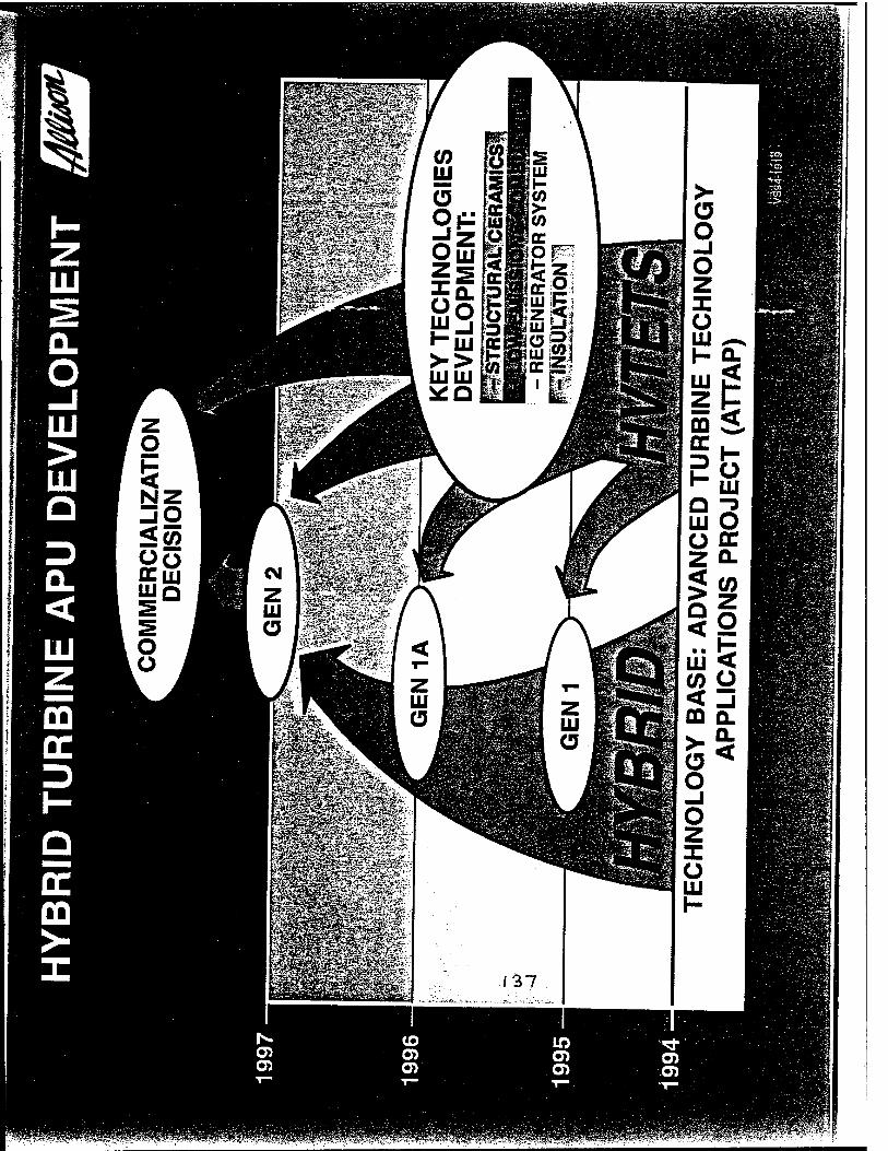
> (3 O -j
KmdFSl O z X
HJw ^A o UJ
fijjpKifii S5f h- LU z CD
LU o
ife
f- uj
HI O
<l ■ ■ rr UJ < (0 Ü < Ü CD GL
*- Q-
137
o UJ

LU
Q_ O LU >
HI Q
(/)
UJ
O O
O HI I- >-
LU
(0
HI
LU DC
o UJ cc LU DC
Li.
</)
Ü
o d
isoo iiNn aaznvwHON
o o d
"^ s <
V ™
DC -
LU -
O x
-
j -
< -
DC -
3 _
H O 3 DC ■ I— to
C > © o © o a C T1
> 00 <D *fr CM *
% - an 3IA SS3 lOOUd
CO
o O) O)
CD 03 O)
to LU to to UJ Ü o DC a. a z < . to w < E LU
to
5 Q
e z o Q UJ to < ffi
Q UJ I- U UJ
o DC a. ii
t- z UJ DC DC
O
< o o UJ > UJ X u <
e Q UJ a UJ UJ z to
Z UJ S UJ > O DC a.
II a UJ DC 5 a UJ DC
n O)
a> (0 >
138

HI
Q_ o LU > LU Q
0) UJ
(3 O
X Ü UJ
UJ
g i-
ffl
o o CO z g (0 m UJ
LU
<
LL
< Q z cc OCX OHIO
3 "v
E Ö o E D)
o o o o
(0 o D)
I 2 !S CO
D) a E
LO CM*
01 > O ■ o. o
o ■ o
im/XON wß 3"0
SSE LugO
0> 3
«*- Ö)
o z E D)
X LU Q
X O
J - o
|anj ß>|/oo uiß 'X3QNI 00
139

Appendix N
40

^ffi^^^^^^^i^^^^
Super Precision Angular Contact Ball Bearings
r-B-
*D
7000C Series
i— a—'
4>d
Boundary Dimensions Basic Load Ratings Limiting Speeds2*
mm lbs Kgt r pm
Bearing d D B r1» IV» C r Cor c r C or
Grease Oil
Number min. min.
7000 C 10 26 8 0.3 0.15 1200 560 540 254 60000 85000
7001 C 12 28 8 0.3 0.15 1300 650 590 296 53000 75000
7002 C 15 32 9 0.3 0.15 1400 760 635 345 45000 63000
7003C 17 35 10 0.3 0.15 1500 860 675 390 40000 56000
7004 C 20 42 12 0.6 0.3 2500 1500 1130 665 34000 48000
7005 C 25 47 12 0.6 0.3 2600 1700 1190 755 30000 43000
7006 C 30 55 13 1 0.6 3400 2300 1540 1050 24000 36000
7007C 35 62 14 1 0.6 4300 3100 1950 1390 22000 30000
7008 C 40 68 15 1 0.6 4600 3600 2100 1620 19000 28000
7009 C 45 75 16 1 0.6 5500 4300 2490 1960 18000 26000
7010 C 50 80 16 1 0.6 5800 4900 2650 2230 16000 24000
7011 C 55 90 18 1.1 0.6 7700 6400 3500 2920 14000 20000
7012 C 60 95 18 1.1 0.6 7900 6900 3600 3150 14000 19000
7013 C 65 100 18 1.1 0.6 8400 7700 3800 3500 13000 18000
7014 C 70 110 20 1.1 0.6 10600 9700 4800 4400 12000 17000
7015 C 75 115 20 1.1 0.6 10800 10200 4900 4650 11000 16000
7016 C 80 125 22 1.1 0.6 13200 12500 6000 5650 10000 15000
7017 C 85 130 22 1.1 0.6 13500 13200 6150 6000 10000 14000
7018 C 90 140 24 1.5 1 16000 15500 7300 7050 9000 13000
7019 C 95 145 24 1.5 1 16500 16400 7500 7450 9000 13000
7020 C 100 150 24 1.5 1 17000 17400 7700 7900 8500 12000
7021 C 105 160 26 2 1 19800 20100 9000 9100 8000 11000
7022 C 110 170 28 2 1 23800 23400 10800 10600 7500 11000
7024 C 120 180 28 2 1 25100 26200 11400 11900 7100 10000
7026 C 130 200 33 2 1 29100 30900 13200 14000 6300 9000
7028 C 140 210 33 2 1 29800 32600 13500 14800 6000 8500
7030 C 150 225 35 2.1 1.1 34000 37900 15400 17200 5600 8000
7032 C 160 240 38 2.1 1.1 38300 43500 17400 19700 5300 7500
7034 C 170 260 42 2.1 1.1 46100 52500 20900 23900 4800 7100
7036 C 180 280 46 2.1 1.1 51500 62000 23300 28100 4500 6700
7038 C 190 290 46 2.1 1.1 55500 69500 25100 31500 4300 6300
7040 C 200 310 51 2.1 1.1 59500 76000 27000 34500 4000 6000
Note:1) Chamfer dimensions conform to new JIS; however, some chamfer dimensions conforming to old JIS are also used until conversion to new JIS is completed.
21 For application of limiting speeds, please refer to page 174.
f
•
t
M
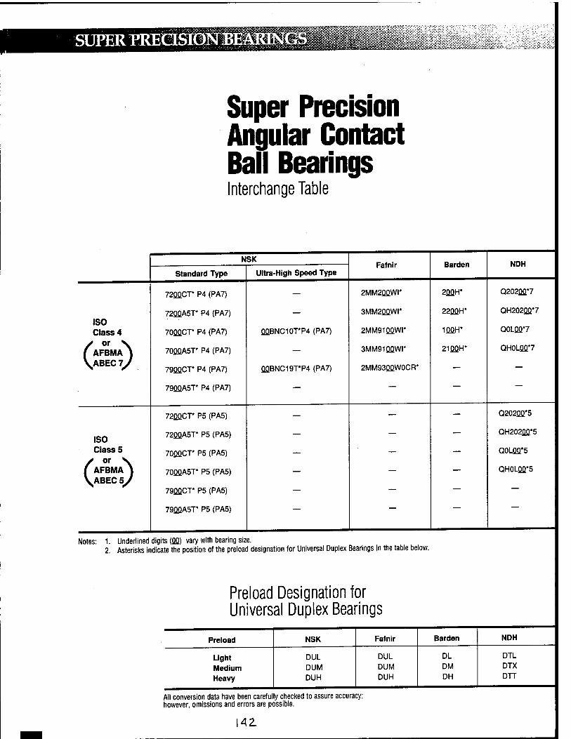
SUPER PRECISION BEARINGS llIilllilll§lH • ■!« ;:«■;:* s: w
Super Precision Angular Contact Ball Bearings Interchange Table
N
Standard Type
SK
Ultra-High Speed Type Fafnir Barden NDH
72QQCT* P4 (PA7) — 2MM2QQWI* 2QQH* Q202QQ*7
icn 72QQA5T* P4 (PA7) — 3MM2QQWI* 22QQH* QH202QQ*7
Class 4 70QQCT* P4 (PA7) QQBNC10T*P4 (PA7) 2MM91QQWr 1QQH* Q0LQQ*7
[AFBMA ) \ABEC 7/
70QQA5T* P4 (PA7) — 3MM91QQWI* 21QQH* QH0LQQ*7
79QQCT* P4 (PA7) QQBNC19T*P4 (PA7) 2MM93QQW0CR* — —
79QQA5T* P4 (PA7) — — — __
72QQCT* P5 (PA5) — — — Q202Qfl*5
ISO 72QQA5T* P5 (PA5) — — — QH202QQ*5
Class 5 70QQCT* P5 (PA5) — — — Q0LQQ*5
(AFBMA ) \ABEC 5/
70QQA5T* P5 (PA5) — — — QH0LQQ*5
79QQCT* P5 (PA5) ~~
79QQA5T* P5 (PA5) — —
Notes: 1. Underlined digits (flfl) vary with bearing size. 2. Asterisks indicate the position of the preload designation for Universal Duplex Bearings in the table below.
Preload Designation for Universal Duplex Bearings
Preload NSK Fafnir Barden NDH
Light DUL DUL DL DTL
Medium DUM DUM DM DTX
Heavy DUH DUH DH DTT
All conversion data have been carefully checked to assure accuracy; however, omissions and errors are possible.
\AZ ^■H
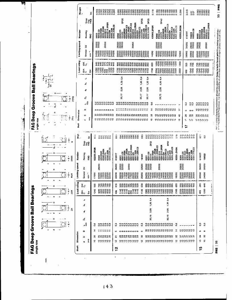
c c< wcu.
10
C
a
a « a
I 2 a a
at o *
- -o —
COeOCOCOCOCOCOCOCO C0CDCOCOCOCOCOCDCC ooooooooo 000000000
pppopppoooppooo ÖÖÖÖÖÖÖÖÖÖÖÖÖÖÖ
CO CO to
. = 2 CM
in in nrtr = = w — — _ n; N N 9oC^NNN™~
OJOJNNCMOJNC4CM OOOOOOOOO ooooooooo COCDCOCDCDCOCOtOCO
OO oo OO oo CD co
ooooooooo ooooooooo ooooooooo CMCMi-'-CMi-CMCMCM
n Ü W Oeccc S w **_
CC CC <" «Ifl J ü-^OCDCff
9ZCCOC«NNNNN£™«W OKMEMCMCMCMCMCMCMCMCMCMCMCMCM ooooooooooooooo CMCMCMCMCMCMCMCMCMCMCMCMCMCMCM (OCOCOCOCDCDCOCOCOCOtOCDCOCOCD
ooo o ooo o ooo o totoco CO CMCMCM CM
ooooooooooooooo ooooooooooooooo ooooooooooooooo OOO'^'V^'VO'^-OOOOOO cgc\]c\jT-T-T-T-c\jT-cvic\jevje\jeMOJ
i— CO CO CO CO CO CO CO CO CO CO CO i- T- i-i- T- *- r~ i- — i- i- CM
ö odddddbood ©
CO CO O co OC
ttcr no« -s «2« 9*a: tt
^ZCC^CM.NN^CM CM CM CM CM CM CM CM CM CM CM CM O OOOOOOOOOO CO CO CO CO CO CO CO CO CO CO CO CM CO CO CO CO (0 CO CO CO CO CO CO
OOO OOO OOO CM CM CM CM CM CM
OOOOOOOOOO OOOOOOOOOO OOOOOOOOOO COCOCOCMCMCMCOCOCOCO
(Hi
oooommooo COCOCDCO^'^'COCOCO
oooo ooo mimnmooioifitn CMCMCMCMCOCOCMCMCM i-T-^^aicni-'-T-
ooooooooooooooo mifliflimoioiflncoLoifliomioio COCOCOCOCOCOCOCOCOCOCOCOCOCOCO
ooooooooooooooo cocoeocococoeocMCMcoeococococo N.r-r-.N-r^t^r-.cocor'-r-.e-r-.r'-.r-.
OOOOOOOOOO OOOOOOOOOO eMCMCMCMCMCMCMCMCMCM
OOOOOOOOOO inminininininininLn CMCMCMCMCMCMCMCMCMCM
CO CO CO CO CO CO CO T- J^N. CO CO CO CO CO CO p Op OOOOOO d do doodad
a 2
COCOCOCOCOCOCOCOCOCOCOCOCOCOCO
o" o" do" o" o"b" o" o" o" o" o~ o" d o"
cncncncncncncncncn COCOCOCOCOCOCOCOCOCO h-
"5 S CO u
eon oo oo coco ,-,~ oo OO o
oo o oo oo o COCO CM CM CMCM CM
OO OO oooooo
OOOOOO CM CM CM CM CM CM i-*- CM *-
mm coco r-F-. r».^. K h-ioin
oo oooooo •«j-^r coco CO CO CO CO o o
> 3 "C r.
5 > 3 =
o c
o fc
~ c
in in i/i in m mm m m m in in in in in in men in m m in in in m mmmm minmtnmm m
(0 0) e 'C a a> a 75 a
I 8 o a o> * >
- 13 —
-» -o -
£ _ .». -,-.-.«.,. ^ -, ^ -, -, -, ~, «■> o V- V^ V^ '^ ~ '^ ^ 333333333 oj r^ i^ i^i i^ ^ tNj ,^4 <si «jy .JVI ivj ._v \^ '_' Ü' \2 '_-''—''—' U-' ll 3 *
nC9
OOOOOO o ooooooooo o OO^C3^C>O^OOOOC3 C3000C3 o o
OC CO „ OC CO
OC CO 0C O « I 3 Ü » CO
oca CM « °. OC (0
CO cc o
■O c
EC CM
d «CM^CMM h- (TOTmin OCOC
9 Z OC W N N N N N N « ^
cc CM ?31 n t OC N IM t-
CM CM
E 3 z < ooooooooo ooooooooooooo CM CO
CO CO CO CO CO CO CO co COCDCOCOCOCOCOCOCO (0(0CO<O(O<O<O(OCDC0COCOCO CO ^~ ■o 0)
a ooo o oo o o ooo o
O CM CO CO CO CO CO CO CMCM
c o r> ooooooo o o CO ooooooooooooo o ooooooo
ooooooooooooo CD E CO
CM*- *- CM CM CM CO CMCMi-i-CM^-CMCMCM CM CMCMCMT-T-I-CM'-CMCMCMCMCM 1-
. O) 15 0
CO ooootninooo in ooooooo in o CO en : « in r^ r*. r-- f*- r» h- CM mininincocoininin m cocococococoinincococococo CO en o> en en en en oi \
r *J ooooooooooooo o ooooooo o m CO ooooooo
£ CO CO CO CO CO CO in : _l ■aO T-^-y-y-j-T- ■*r *:
^ ■*
^ o o in in CO CO
n
CO CO
cc? CM CM
m in
CO CO
c CO CO CO CO CO CO to CO cococococococococo CO CDCOCOCOCOCOCDCOCOCOCOCOCO . co CO CO
L_«e o oooooo o ooooooooo o ooooooooooooo o o o
m TT _____,- l£> ......... CO
ooooooooooooo ■*r CM CM CM CM CM CM CM m CO
CM
C O
'5j c 0)
CMCMCMCMCMCMCMCMCMCMCMCMCM CM h-1*-. i^- r^ r*- r— r^ CO 10 CO CO CO CO CO CM CMCMCMCMCMCMCMCMCM CO eococococococococococococo CO CO CO CO CO CO CO CO
b E E oooooo CM eMCMCMCMCMCMCMCMCM CM CMCMCMCMCMCMCMCMCMCMCMCMCM CM CM CM CM CM CM CM CM in in
■D ,-,-T-,-,--r- "" ,-,~'*"T~,-,-'r"1"*" *~ T-n-m-T-T-^T-T-T-r* *~ r- i- i- i- T- T- T-
CD CM w CO
V T- ^ ,
ligSJHWW^^l^P'^
(43