D:\Technical Pubs\00-105E-9\00- - 0x4d.net
25
TO GO DIRECTLY TO THE TECHNICAL ORDER, CLICK ON THE CONTINUE BUTTON. WELCOME TO TECHNICAL ORDER 00-105E-9, 1 FEBRUARY 2006, REVISION 11. TO SEE THE SEGMENT INFORMATION CHANGE NOTICE, CLICK ON THE NOTICE BUTTON. TO CONTACT THE TECHNICAL CONTENT MANAGER , CLICK ON THE CONTACT BUTTON. CONTINUE NOTICE CONTACT TO NAVIGATE CLICK ON THE BOOKMARKS AND CLICK ON THE (+) SYMBOLS, THEN CLICK ON SUBJECT LINKS TO GO TO SPECIFIC VIEWS IN THIS SEGMENT. THIS IS SEGMENT 2 COVERING CHAPTER 4.
Transcript of D:\Technical Pubs\00-105E-9\00- - 0x4d.net
TO GO DIRECTLY TO THE TECHNICAL ORDER, CLICK ON THE CONTINUE BUTTON.
WELCOME TO TECHNICAL ORDER 00-105E-9, 1 FEBRUARY 2006, REVISION 11.
TO SEE THE SEGMENT INFORMATION CHANGE NOTICE, CLICK ON THE NOTICE BUTTON.
TO CONTACT THE TECHNICAL CONTENT MANAGER , CLICK ON THE CONTACT BUTTON.
CONTINUE
NOTICE
CONTACT
TO NAVIGATE
CLICK ON THEBOOKMARKS ANDCLICK ON THE (+)SYMBOLS, THEN
CLICK ON SUBJECTLINKS TO GO TOSPECIFIC VIEWS
IN THIS SEGMENT.
THIS IS SEGMENT 2 COVERING CHAPTER 4.
TECHNICAL ORDER 00-105E-9 TECHNICAL CONTENT MANAGER
WRITTEN CORRESPONDENCE:
HQ AFCESA/CEXFATTN: Fire and Emergency Services Egress Manager139 Barnes Drive Suite 1Tyndall AFB, Florida 32403-5319
E-MAIL: [email protected]
INTERNET: HQ AFCESA Fire and Emergency Services PUBLIC WEB PAGE: http://www.afcesa.af.mil/CEX/cexf/index.asp Safety Supplements: http://www.afcesa.af.mil/CEX/cexf/_firemgt.asp
PHONE: (850) 283-6150DSN 523-6150
FAX: (850) 283-6383DSN 523-6383
For technical order improvements, correcting procedures, and other inquiries,please use the above media most convenient.

This page is provided to notifiy the user of any informational changes made to Technical Order 00-105E-9 in this Segment and the currentRevision. Informational changes will be referenced in the Adobe Reader’s Bookmark tool as a designator symbol illustrated as a <[C]> forquick reference to the right of the affected aircraft. The user shall insure the most current information contained in this TO is used for hisoperation. Retaining out of date rescue information can negatively affect the user’s operability and outcome of emergencies. If the user printsout pages his unit requires, the user shall print the affected page(s), remove and destroy the existing page(s), and insert the newly printedpage(s) in the binder provided for that purpose. A Master of this TO shall be retained in the unit’s library for reference, future printingrequirements and inspections.
CHAPTER AIRCRAFT PAGE EXPLANATION OF CHANGE
None.
SEGMENT 2 INFORMATION CHANGE NOTICE

TO 00-105E-9
Chapter 4 Cover
NOTE
Chapter 4 contains emergency rescue andmishap response information for the following aircraft:
USAF A-10USAF A-37

T.O. 00-105E-9
CHAPTER 4
U.S. AIR FORCE
ATTACK
AEROSPACE EMERGENCY RESCUEAND MISHAP RESPONSE INFORMATION
4-1. INTRODUCTION AND USE.
4-2. This section contains emergency rescue andmishap response information illustrations in alpha-numerical order relative to type and model of aircraft.This arrangement of illustrations is maintained fromChapter 4 throughout the remainder of the publica-tion.
4-3. GENERAL ARRANGEMENT.
4-4. Aircraft type designation has been positionedin the upper right corner of the horizontal illustrationfor rapid identification. Additional aids to rapid orien-tation are:
a. Recent technological advances in avia-tion have caused concern for the modern firefighter.Aircraft hazards, cabin configurations, airframe ma-terials, and any other information that would be help-ful in fighting fires, the locating and rescue of per-sonnel will be added as the information becomesavailable.
b. Suggested special tools/equipment arelisted in the upper left corner, on the Aircraft/Entrypage of each listed aircraft.
c. Procedural steps covering emergency/normal entrances, cut-ins, engine/APU shutdown,safetying ejection/escape systems, and aircrew ex-traction are outlined on the left side of each pagewith coordinated illustrations on the right.
d. Illustrations located on right side of pagesare coordinated with text by numerals and small let-ters depicting both paragraph and subparagraph onthe page.
e. Each illustration is consistently coloredand/or pattern keyed to highlight essential emergencyrescue information.
f. Details are pulled directly from the illus-tration to highlight an area, thus eliminating unnec-essary searching for desired information.
4-1

A-10T.O
. 00-105E-9
A-10. AIRCRAFT PAINT SCHEME
1
A-10T.O
. 00-105E-9
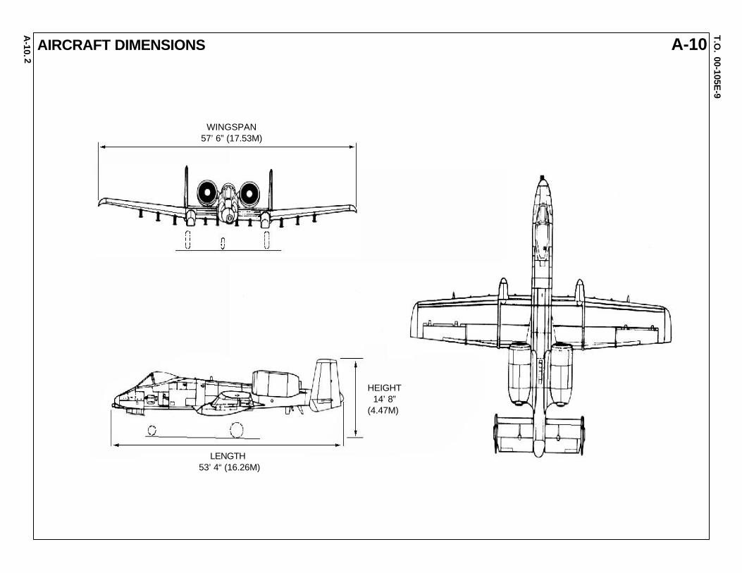
A-10. AIRCRAFT DIMENSIONS
2
WINGSPAN57’ 6” (17.53M)
LENGTH53’ 4“ (16.26M)
HEIGHT 14’ 8”(4.47M)

A-10T.O
. 00-105E-9
A-10.
AIRCRAFT SKIN PENETRATION POINTS
3
The APU must be shut down beforeapproaching the APU penetration point.
GUN BAY (LEFT SIDE)F.S. 203 - 206 W.L. 77F.S. 232 - 236 W.L. 77
APU (LEFT SIDE)F.S. 565 W.L. 84
GUN BAY (RIGHT SIDE)F.S. 279 - 285 W.L. 85
WARNING

A-10T.O
. 00-105E-9
A-10. 4
AIRCRAFT SKIN PENETRATION POINTS - Continued
RIGHT ENGINE NACELLEN.S. 190 1 O’CLOCK POSITION
NOTE: Fuel lines are located at the 2 and 4 o’clock positions. Avoid penetrating these areas.
LEFT ENGINE NACELLEN.S. 170 11 O’CLOCK POSITION
LEFT ENGINE NACELLEN.S. 188 7 O’CLOCK POSITION
RIGHT ENGINE NACELLEN.S. 188 5 O’CLOCK POSITION
NOTE: Hydraulic lines are located at the 8 and 10 o’clock positions. Avoid penetrating these areas.
A-10T.O
. 00-105E-9
A-10.5
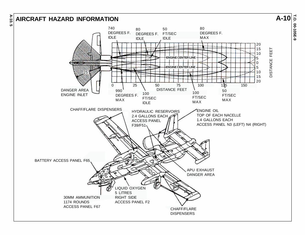
AIRCRAFT HAZARD INFORMATION740DEGREES F.IDLE
80DEGREES F.IDLE
50FT/SECIDLE
80DEGREES F.MAX
201510505101520
DIS
TA
NC
E F
EE
T
25’
990DEGREES F.MAX
100FT/SECIDLE
DISTANCE FEET0 25 50 75 100 125 150
ENGINE CENTER LINE
ENGINE CENTER LINE
100FT/SECMAX
50FT/SECMAX
DANGER AREAENGINE INLET
ENGINE OILTOP OF EACH NACELLE1.4 GALLONS EACHACCESS PANEL N3 (LEFT) N4 (RIGHT)
HYDRAULIC RESERVOIRS2.4 GALLONS EACHACCESS PANELF39/F51
CHAFF/FLARE DISPENSERS
BATTERY ACCESS PANEL F65
30MM AMMUNITION1174 ROUNDSACCESS PANEL F67
LIQUID OXYGEN5 LITRESRIGHT SIDEACCESS PANEL F2
CHAFF/FLAREDISPENSERS
APU EXHAUSTDANGER AREA
A-10T.O
. 00-105E-9
A-10.6
600600
323
323496
496
EXTERNALBATTERYSWITCH
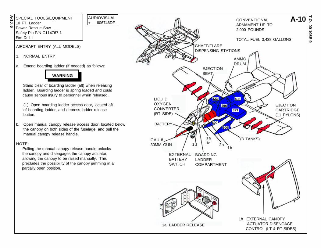
GAU-830MM GUN
BOARDINGLADDERCOMPARTMENT
EJECTIONCARTRIDGE(11 PYLONS)
(3 TANKS)2a
1a1c1d
1b
BATTERY
LIQUIDOXYGENCONVERTER(RT SIDE)
EJECTIONSEAT
AMMODRUM
CHAFF/FLAREDISPENSING STATIONS
CONVENTIONALARMAMENT UP TO2,000 POUNDS
TOTAL FUEL 3,438 GALLONS
SPECIAL TOOLS/EQUIPMENT10 FT. LadderPower Rescue SawSafety Pin P/N C114767-1Fire Drill II
AUDIOVISUAL+ 606746DF
1b EXTERNAL CANOPY ACTUATOR DISENGAGE CONTROL (LT & RT SIDES)
1a LADDER RELEASE
AIRCRAFT ENTRY (ALL MODELS)
1. NORMAL ENTRY
a. Extend boarding ladder (if needed) as follows:
Stand clear of boarding ladder (aft) when releasing ladder. Boarding ladder is spring loaded and could cause serious injury to personnel when released.
(1) Open boarding ladder access door, located aftof boarding ladder, and depress ladder releasebutton.
b. Open manual canopy release access door, located belowthe canopy on both sides of the fuselage, and pull themanual canopy release handle.
NOTE: Pulling the manual canopy release handle unlocks the canopy and disengages the canopy actuator, allowing the canopy to be raised manually. This precludes the possibility of the canopy jamming in a partially open position.
WARNING
A-10T.O
. 00-105E-9
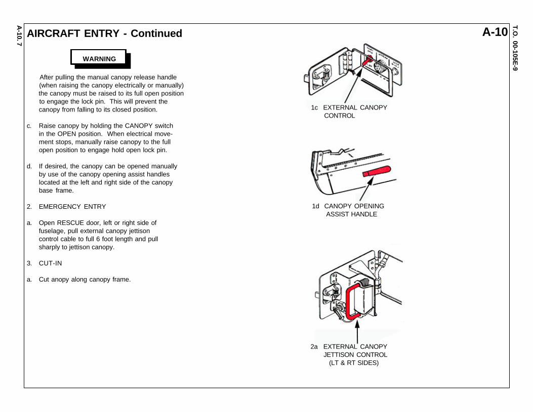
A-10. AIRCRAFT ENTRY - Continued
After pulling the manual canopy release handle (when raising the canopy electrically or manually) the canopy must be raised to its full open position to engage the lock pin. This will prevent the canopy from falling to its closed position.
c. Raise canopy by holding the CANOPY switchin the OPEN position. When electrical move-ment stops, manually raise canopy to the fullopen position to engage hold open lock pin.
d. If desired, the canopy can be opened manuallyby use of the canopy opening assist handleslocated at the left and right side of the canopybase frame.
2. EMERGENCY ENTRY
a. Open RESCUE door, left or right side offuselage, pull external canopy jettisoncontrol cable to full 6 foot length and pullsharply to jettison canopy.
3. CUT-IN
a. Cut anopy along canopy frame.
2a EXTERNAL CANOPY JETTISON CONTROL (LT & RT SIDES)
1d CANOPY OPENING ASSIST HANDLE
1c EXTERNAL CANOPY CONTROL
7
WARNING
A-10T.O
. 00-105E-9
A-10.
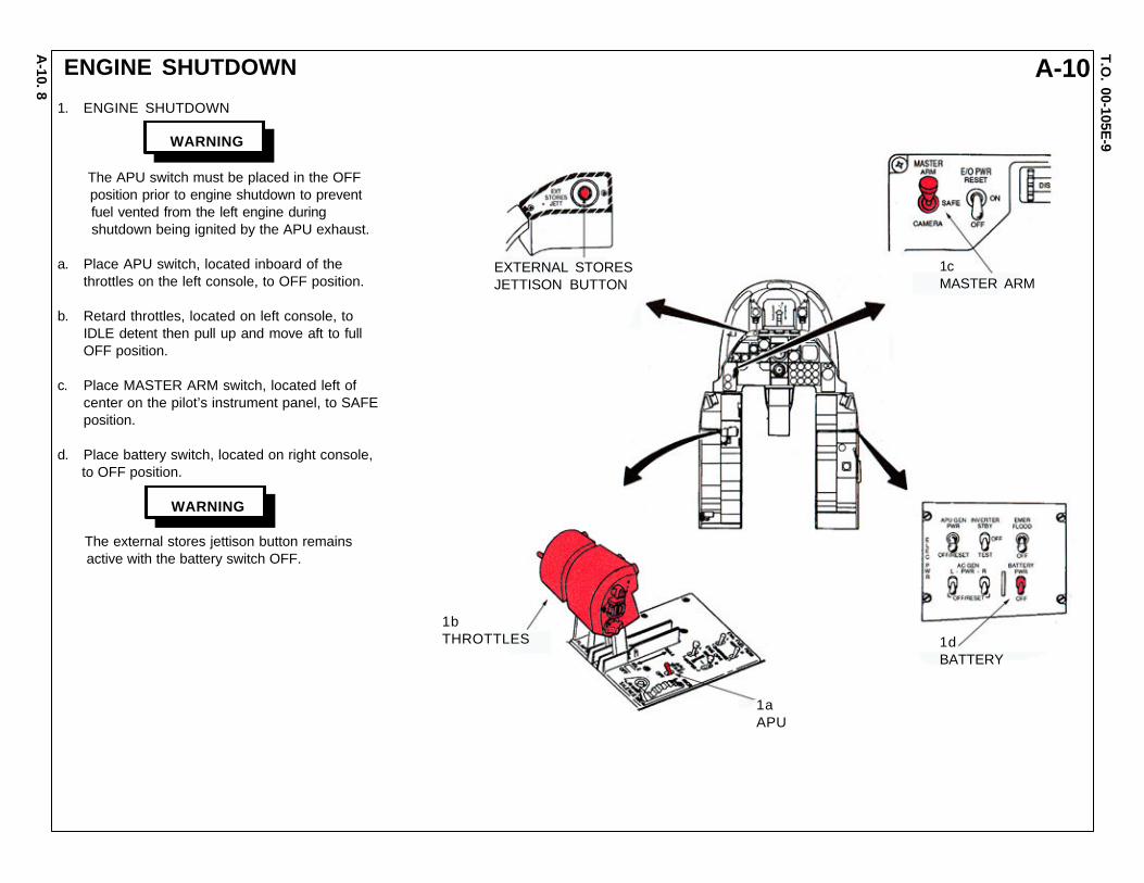
ENGINE SHUTDOWN
1. ENGINE SHUTDOWN
The APU switch must be placed in the OFF position prior to engine shutdown to prevent fuel vented from the left engine during shutdown being ignited by the APU exhaust.
a. Place APU switch, located inboard of thethrottles on the left console, to OFF position.
b. Retard throttles, located on left console, toIDLE detent then pull up and move aft to fullOFF position.
c. Place MASTER ARM switch, located left ofcenter on the pilot’s instrument panel, to SAFEposition.
d. Place battery switch, located on right console, to OFF position.
The external stores jettison button remains active with the battery switch OFF.
EXTERNAL STORESJETTISON BUTTON
1cMASTER ARM
1dBATTERY
1aAPU
1bTHROTTLES
8
WARNING
WARNING
A-10T.O
. 00-105E-9
A-10.9
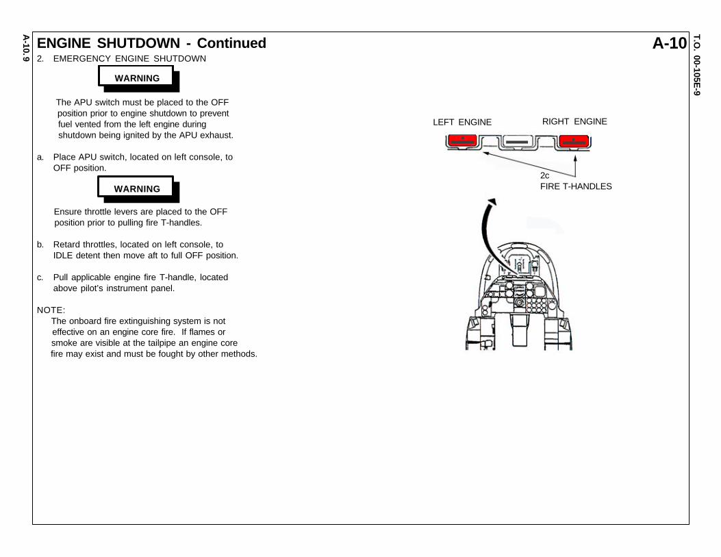
ENGINE SHUTDOWN - Continued2. EMERGENCY ENGINE SHUTDOWN
The APU switch must be placed to the OFF position prior to engine shutdown to prevent fuel vented from the left engine during shutdown being ignited by the APU exhaust.
a. Place APU switch, located on left console, toOFF position.
Ensure throttle levers are placed to the OFF position prior to pulling fire T-handles.
b. Retard throttles, located on left console, toIDLE detent then move aft to full OFF position.
c. Pull applicable engine fire T-handle, locatedabove pilot’s instrument panel.
NOTE: The onboard fire extinguishing system is not effective on an engine core fire. If flames or smoke are visible at the tailpipe an engine core fire may exist and must be fought by other methods.
LEFT ENGINE RIGHT ENGINE
2c FIRE T-HANDLES
WARNING
WARNING
A-10T.O
. 00-105E-9
A-10.10
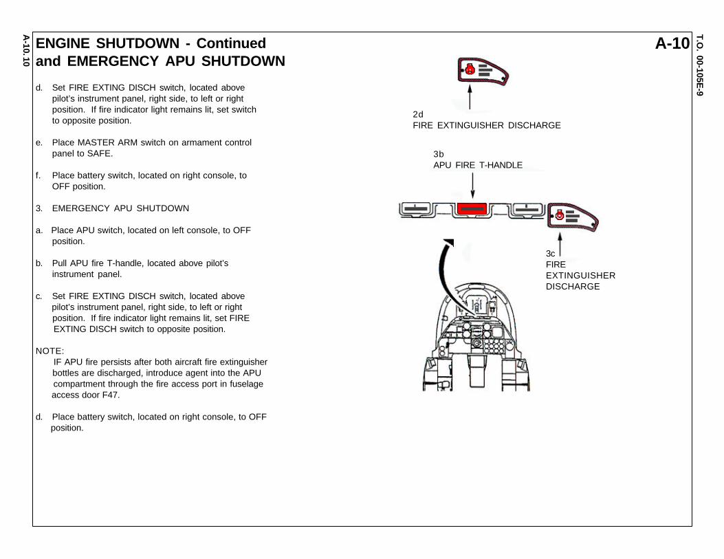
ENGINE SHUTDOWN - Continuedand EMERGENCY APU SHUTDOWN
d. Set FIRE EXTING DISCH switch, located abovepilot’s instrument panel, right side, to left or rightposition. If fire indicator light remains lit, set switchto opposite position.
e. Place MASTER ARM switch on armament controlpanel to SAFE.
f. Place battery switch, located on right console, toOFF position.
3. EMERGENCY APU SHUTDOWN
a. Place APU switch, located on left console, to OFFposition.
b. Pull APU fire T-handle, located above pilot’sinstrument panel.
c. Set FIRE EXTING DISCH switch, located above pilot’s instrument panel, right side, to left or right position. If fire indicator light remains lit, set FIRE EXTING DISCH switch to opposite position.
NOTE: IF APU fire persists after both aircraft fire extinguisher bottles are discharged, introduce agent into the APU compartment through the fire access port in fuselage access door F47.
d. Place battery switch, located on right console, to OFF position.
2dFIRE EXTINGUISHER DISCHARGE
3bAPU FIRE T-HANDLE
3cFIREEXTINGUISHERDISCHARGE

A-10T.O
. 00-105E-9
A-10.11
EJECTION SEAT INDICATOR1. EJECTION SEAT INDICATOR
A Seat Armed Indicator located on the upper right side of the seat can indicate WHITE for OK and RED for SEAT ARMED. This indicates that the Advanced Re- covery Sequencer (ARS) battery condition is serviceable or expended. If expended, the white sealant will be punctured by a protruding red pin. If this is a recent condition, it will take two hours for the seat to be considered safe to work around or remove. Electrical battery power is required to energize the recovery sequencer circuits for the numerous explosives on the seat. Use extreme caution and judgement in this case. If time permits, call the local Egress Shop before pro- ceeding. If emergency exists and time does not allow inspection by the Egress Shop, sever all exposed ballistic lines including top of seat for the rocket catapult.
WARNING ARS INDICATOR
ARMED SAFE
ARMEDSIDE VIEW
NOTE: Do not touch indicator sealant when checking condition. Frequent touching wears off sealant exposing tip of red pin indicating a false ARMED ARS condition.

A-10T.O
. 00-105E-9
A-10.12
EJECTION SYSTEM SAFETYINGand AIRCREW EXTRACTION
The seat is armed regardless of canopy position. Jettisoning the aircraft canopy automatically arms the ACES II ejection seat.
1. NORMAL SAFETYING OF EJECTION SEAT
a. Rotate Ground Safety Lever, located left side of seat directly aft of the left Ejection Control Handle, UP and FORWARD.
NOTE: The Ejection Control Handle safety pin can ONLY be installed from the forward inboard side of the left handle.
b. Install safety pin in left Ejection Control Handle.c. Install safety pin in the Emergency Manual Chute Handle,
located on right side of seat.
2. EMERGENCY SAFETYING OF EJECTION SEAT AFTER CANOPY JETTISON
Rotating the Ground Safety Lever in this situation does not adequately prevent the possibility of inadvertent ejection.
a. Rotate Ground Safety Lever, located left side of seat directlyaft of the left Ejection Control Handle, UP and FORWARD.
b. Insert safety pin in left Ejection Control Handle.c. Cut ballistic hoses on left and right sides of seat, above dis-
connects, to prevent ballistic gas from actuating ejection devices.
3. AIRCREW EXTRACTION
NOTE: The Emergency Manual Chute Handle, located on right side of seat directly behind the right Ejection Control Handle, DOES NOT release restraint system. Manual release of each restraint and lead is necessary prior to extraction.
a. Release lap belt by lifting cover and pulling release bar.b. Release left and right survival kit buckles by depressing PUSH TO
RELEASE tab on each buckle.c. Release left and right should harness fittings by lifting cover and pulling release bar on each fitting.
1b, 2bSAFETYPIN
1a, 2aGROUNDSAFETYLEVER(SAFE POSITION)
3bSURVIVALKITBUCKLES
2cBALLISTICGAS HOSEANDDISCONNECT
3cSHOULDERHARNESSFITTINGS
1cEMERGENCY MANUALCHUTE HANDLE
1cSAFETY PIN
1b, 2bEJECTIONCONTROLHANDLES
3aLAP BELT
WARNING
WARNING
ARMED SAFE
ARMED
ARS INDICATOR
NOTE: Do not touch indicator sealant when checking condition. Frequent touching wears off sealant exposing tip of red pin indicating a false ARMED ARS condition.SIDE
VIEW

A-37T.O
. 00-105E-9
A-37. AIRCRAFT PAINT SCHEME
1

A-37T.O
. 00-105E-9
A-37. AIRCRAFT DIMENSIONS
LENGTH 29’ 3” (8.9 M)
HEIGHT 9’ 2”(2.8 M)
WINGSPAN 33’ 8” (10.2 M)
2
A-37T.O
. 00-105E-9
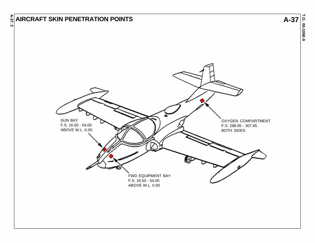
A-37. AIRCRAFT SKIN PENETRATION POINTS
GUN BAYF.S. 16.50 - 54.00ABOVE W.L. 0.00
FWD EQUIPMENT BAYF.S. 16.50 - 54.00ABOVE W.L. 0.00
OXYGEN COMPARTMENTF.S. 288.95 - 307.45BOTH SIDES
3

A-37T.O
. 00-105E-9
A-37.4
AIRCRAFT HAZARD INFORMATION
FEET 0 2 4 6 8 10 12 14 16 18 20 22 24 26 28 30 32 34 36 38 40
EXHAUST TEMPERATURE(DEGREES F)
1100 700 500 400 300 200 150
1700 1200 800 600 400 200 100 70EXHAUST VELOCITY (FT/SEC)
ENGINE EXHAUST DUCT
TURBINE DISENTEGRATION
ENGINE AIR INTAKE DUCT100% RPM
12 FT
12 FT
ENGINE AIR INTAKE DUCT
Suction at the engine intake duct is sufficientto kill or severely injure personnel drawn into,or against, the duct.
WARNING
1500
FT
A-37T.O
. 00-105E-9
A-37.5
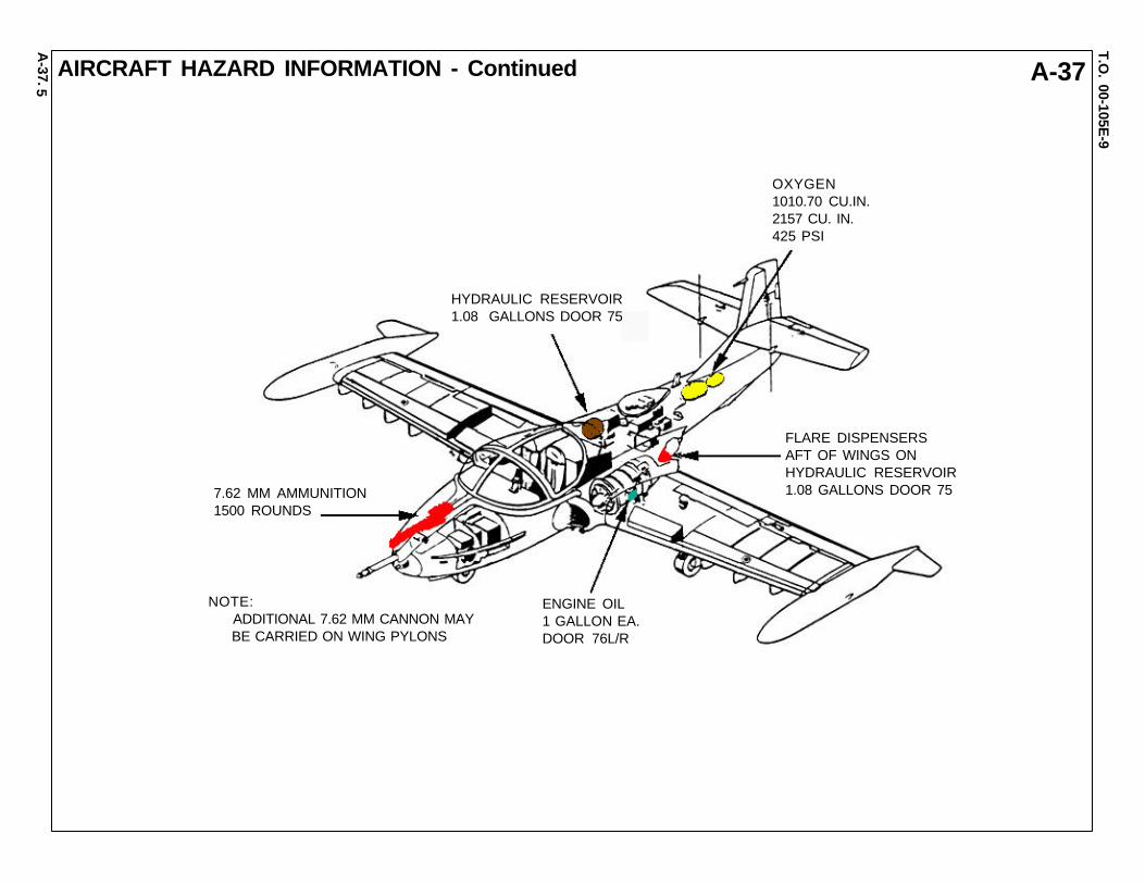
AIRCRAFT HAZARD INFORMATION - Continued
HYDRAULIC RESERVOIR1.08 GALLONS DOOR 75
OXYGEN1010.70 CU.IN.2157 CU. IN.425 PSI
FLARE DISPENSERSAFT OF WINGS ONHYDRAULIC RESERVOIR1.08 GALLONS DOOR 75
ENGINE OIL1 GALLON EA.DOOR 76L/R
7.62 MM AMMUNITION1500 ROUNDS
NOTE: ADDITIONAL 7.62 MM CANNON MAY BE CARRIED ON WING PYLONS
A-37T.O
. 00-105E-9
A-37.6
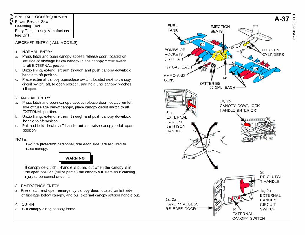
SPECIAL TOOLS/EQUIPMENTPower Rescue SawDearming ToolEntry Tool, Locally ManufacturedFire Drill II
FUELTANK
EJECTIONSEATS
OXYGENCYLINDERS
BOMBS ORROCKETS(TYPICAL)
97 GAL. EACH
97 GAL. EACH
AMMO ANDGUNS
BATTERIES4a
3 aEXTERNALCANOPYJETTISONHANDLE
1b, 2bCANOPY DOWNLOCKHANDLE (INTERIOR)
1a, 2aCANOPY ACCESSRELEASE DOOR 1c
EXTERNALCANOPY SWITCH
2cDE-CLUTCHT-HANDLE
1a, 2aEXTERNALCANOPYCIRCUITSWITCH
90
99
99
79
90
AIRCRAFT ENTRY ( ALL MODELS)
1. NORMAL ENTRYa. Press latch and open canopy access release door, located on left side of fuselage below canopy, place canopy circuit switch to aft EXTERNAL position.b. Unzip lining, extend left arm through and push canopy downlock handle to aft position.c. Place external canopy open/close switch, located next to canopy circuit switch, aft, to open position, and hold until canopy reaches full open.
2. MANUAL ENTRYa. Press latch and open canopy access release door, located on left side of fuselage below canopy, place canopy circuit switch to aft EXTERNAL position.b. Unzip lining, extend left arm through and push canopy downlock handle to aft position.c. Pull and hold de-clutch T-handle out and raise canopy to full open position.
NOTE: Two fire protection personnel, one each side, are required to raise canopy.
WARNING
If canopy de-clutch T-handle is pulled out when the canopy is in the open position (full or partial) the canopy will slam shut causing injury to personnel under it.
3. EMERGENCY ENTRYa. Press latch and open emergency canopy door, located on left side of fuselage below canopy, and pull external canopy jettison handle out.
4. CUT-INa. Cut canopy along canopy frame.

A-37T.O
. 00-105E-9
A-37.7
ENGINE SHUTDOWN1. ENGINE SHUTDOWN
NOTE:• Seats must be safetied before engines are shutdown at co-pilot’s throttle.• Pilot’s throttle can not be placed in the full CUT-OFF position.
a. Raise and retard throttles on pilot’s quadrant, located on left console, to full aft CUT-OFF position.
b. Raise and retard throttles on co-pilot’s quadrant located on center console, to full aft CUT-OFF position.
NOTE: If step b does not shutdown engines, pull fueld shut-off T-handles, located top center of instrument panel.
c. Pull Fuel Shutoff T-handles, located on top center instrument panel, if applicable.
d. Place battery switch, located on pilot’s lower instrument panel, to OFF position.
1aPILOT’STHROTTLE
1cFUEL SHUTOFFT-HANDLES
1bCO-PILOT’STHROTTLES
1dBATTERY SWITCH

A-37T.O
. 00-105E-9
A-37.8
SAFETYING EJECTION SYSTEMAND AIRCREW EXTRACTION2. NORMAL SAFETYING EJECTION SEAT
a. Insert arming handle safety pins in lower right side of both ejection seats.
3. EMERGENCY SAFETYING EJECTION SEAT
a. Cut catapult hose (T-37 and A-37) located behindheadrest just aft of canopy piecer and cut rocketmotor initiator hose (A-37 only) located on outboardside of both seats. (See yellow heat shrink onhoses.)
4. AIRCREW EXTRACTION
a. Unlatch lap belt and remove shoulder harness fromcrewmember(s).
b. On HUB-12/A lap belt, squeeze together the blackand silver grips of the handle and lift up. Separatebelt. Remove gold key. Remove shoulder harness/negative “G” restraint strap loop ends.
4aLAP BELT
2aARMING HANDLESAFETY PINS
4bHANDLE-SQUEEZE ANDLIFT TO OPEN
SIDE VIEW HBU-12/A LAP BELT
STABILIZATIONPARACHUTECONTAINER
3aCUT CATAPULTHOSE HERE
CANOPY PIERCER
3aCUT ROCKETMOTOR HOSEHERE (A-37 only)
ROCKET MOTORINITIATOR
RAIL STRUCTURE
CATAPULT
DISCONNECT(behind rocket motor)
ROCKET MOTOR(A-37 only)
SAFETY LAP BELT
LEG GUARDHAND GRIP
EJECTION SEAT
VERTICAL ADJUSTMENTCONTROL LEVER
SEAT PAN
INERTIAREELCONTROL