DTC ADR622 ed2 UK SYS 2009-D0351 -...
23
S S A A G G E E M M - - A A D D R R 6 6 2 2 2 2 STM-1/STM-4 Add-drop Multiplexer Product Description DTC SAGEM– ADR622 – AET/SYS/2009-D0351 – 01/09
Transcript of DTC ADR622 ed2 UK SYS 2009-D0351 -...
SSAAGGEEMM--AADDRR662222
STM-1/STM-4 Add-drop Multiplexer
Product Description
DTC SAGEM– ADR622 – AET/SYS/2009-D0351 – 01/09
Abbreviations
DTC SAGEM– ADR622 – AET/SYS/2009-D0351 – 01/09 1/23
EBER Excessive Bit Error Rate
ECC Embedded Communication Channel
EMC ElectroMagnetic Compatibility
ERO Optical Transceiver
ESD Electrostatic discharge
FTTB Fibber To The Building
FTTC/Ca Fibber To The Curb/Cabinet
HDB3 High Density Bipolar 3
ITU-T International Telecommunication Union - Telecommunications
LOF Loss Of Frame
LOS Loss Of Signal
LT (LCT) Local (Craft) Terminal
MEF Metro Ethernet Forum
MMI Man-Machine Interface
MS-AIS Multiplexer Section - Alarm Indication Signal
NMS Network Management System
PABX Private Automatic Branch eXchange
POH Path OverHead
Rx Receiver
SD Signal Degrade
SDH Synchronous Digital Hierarchy
SF Signal Fail
SOH Section OverHead
STM-1 Synchronous Transport Module Level 1
STM-4 Synchronous Transport Module Level 4
STM-16 Synchronous Transport Module Level 16
TSIG Remote signalling input
TUG Tributary Unit Groups
Tx Transmitter
VC Virtual Container
Table of Contents
DTC SAGEM– ADR622 – AET/SYS/2009-D0351 – 01/09 2/23
Second edition January 2009
1. INTRODUCTION ................................................................................................................... 3
2. SDH Optical Multiplexers .................................................................................................... 4
3. APPLICATIONS .................................................................................................................... 5 3.1. Advantages .................................................................................................................................... 5 3.2. Fiber optic access network ............................................................................................................ 6 3.3. DLC Backhauling ........................................................................................................................... 6 3.4. Microwave Networks...................................................................................................................... 6 3.5. Private networkS............................................................................................................................ 6 3.6. Public utility company networks ..................................................................................................... 6 3.7. Ethernet over SDH (EoS)............................................................................................................... 7
4. FUNCTIONAL DESCRIPTION.............................................................................................. 9 4.1. Architecture .................................................................................................................................... 9 4.2. Common Units ............................................................................................................................. 10 4.3. Aggregates................................................................................................................................... 10 4.4. Tributaries .................................................................................................................................... 11 4.5. Protection ..................................................................................................................................... 12 4.6. Synchronisation............................................................................................................................ 13 4.7. Overhead ..................................................................................................................................... 13
5. OPTICAL ENGINEERING................................................................................................... 14 5.1. Optical link budget........................................................................................................................ 14
6. INSTALLATION .................................................................................................................. 15 6.1. Mechanical installation................................................................................................................. 15 6.2. Wiring ........................................................................................................................................... 15
7. SUPERVISION/MAINTENANCE......................................................................................... 16 7.1. Supervision .................................................................................................................................. 16 7.2. Maintenance................................................................................................................................. 18
8. SPECIFICATIONS............................................................................................................... 19 8.1. Electrical and optical specifications ............................................................................................. 19 8.2. Supervisory interfaces ................................................................................................................. 20 8.3. Mechanical specifications ............................................................................................................ 20 8.4. Power supply................................................................................................................................ 20 8.5. consumption................................................................................................................................. 20 8.6. Environmental conditions............................................................................................................. 20 8.7. Guaranteed attenuation ............................................................................................................... 21
INTRODUCTION
DTC SAGEM– ADR622 – AET/SYS/2009-D0351 – 01/09 3/23
1. INTRODUCTION
SAGEM ADR622 is a STM-1 and STM-4 Add-drop Multiplexer" with a 16 VC4 switch non blocking at VC12, VC3, VC4 levels and PDH and SDH protected accesses. SAGEM ADR622 is part of SAGEM Communications SDH solution which also is made of SAGEM ADR155C, SAGEM ADR2500 eXtra, SAGEM ADR10000 and the network management system SAGEM IONOS NMS. This solution offers all the services from 2Mbit/s up to STM-4 including the transport of Ethernet over SDH. This solution is particularly compact, scalable and easy to install and support. Because of its compactness, its high degree of protection, and its enhanced Ethernet over SDH features, SAGEM ADR622 fits with Utility networks, to DLC/DSL backhauling in low density area and to SDH microwave networks.
Very flexible and compact, the SAGEM ADR622 supports traditional TDM traffic through SDH and PDH interfaces but is also optimised for data transport with for instance the GFP2500 unit which has a real Ethernet Switch and offers all the “Ethernet over SDH” enhanced features for Giga Ethernet interfaces. It gives to all Ethernet interfaces the benefits of SDH, maturity, protections, integration into an existing network…
The equipment is SNMP native and has an embedded HTTP server, SAGEM ADR622 is managed by SAGEM SDH Network Management System, IONOS NMS (which also manages SAGEM ADR155c, SAGEM ADR2500eXtra, SAGEM ADR10000 and other products from SAGEM Network division).
SDH Optical Multiplexers
DTC SAGEM– ADR622 – AET/SYS/2009-D0351 – 01/09 4/23
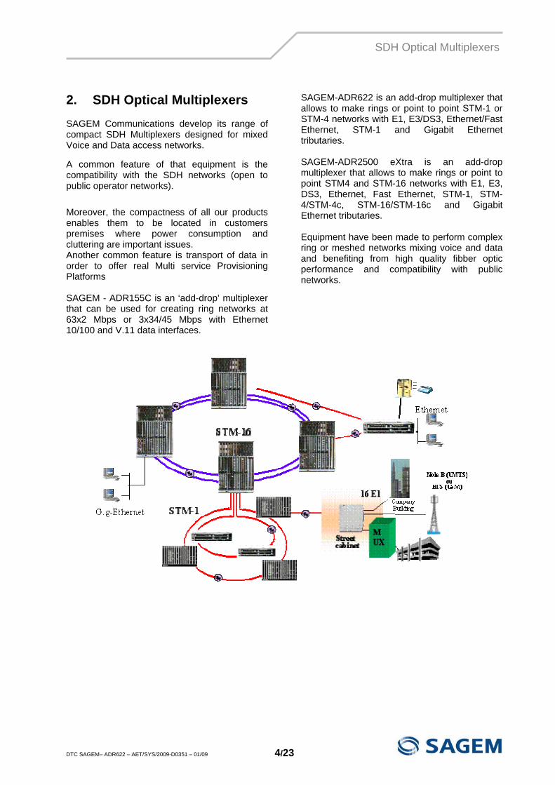
2. SDH Optical Multiplexers
SAGEM Communications develop its range of compact SDH Multiplexers designed for mixed Voice and Data access networks.
A common feature of that equipment is the compatibility with the SDH networks (open to public operator networks). Moreover, the compactness of all our products enables them to be located in customers premises where power consumption and cluttering are important issues. Another common feature is transport of data in order to offer real Multi service Provisioning Platforms SAGEM - ADR155C is an ‘add-drop’ multiplexer that can be used for creating ring networks at 63x2 Mbps or 3x34/45 Mbps with Ethernet 10/100 and V.11 data interfaces.
SAGEM-ADR622 is an add-drop multiplexer that allows to make rings or point to point STM-1 or STM-4 networks with E1, E3/DS3, Ethernet/Fast Ethernet, STM-1 and Gigabit Ethernet tributaries. SAGEM-ADR2500 eXtra is an add-drop multiplexer that allows to make rings or point to point STM4 and STM-16 networks with E1, E3, DS3, Ethernet, Fast Ethernet, STM-1, STM-4/STM-4c, STM-16/STM-16c and Gigabit Ethernet tributaries. Equipment have been made to perform complex ring or meshed networks mixing voice and data and benefiting from high quality fibber optic performance and compatibility with public networks.
APPLICATIONS
DTC SAGEM– ADR622 – AET/SYS/2009-D0351 – 01/09 5/23
3. APPLICATIONS
3.1. ADVANTAGES
3.1.1. TRUE VOICE/DATA INTEGRATION AND PROTECTION
The SAGEM 622 is compliant to SDH standards and it is a versatile add-drop multiplexer with a diversity of access (including 2 Mbps, 34 Mbps, 45 Mbps, Ethernet, Fast Ethernet, 155 and 622 Mbps, evaluative to 2,48 Gbps) with high quality of service (traffic protection).
3.1.2. HIGHLY PROTECTED EQUIPMENT SDH design of ADR622 gives the benefit of standard traffic protections (SNCP and MSP). Cards whose failure could affect the traffic can be protected in 1+1 mode and tributaries can be protected in 1:4.
3.1.3. COMPACT, SIMPLE AND RELIABLE EQUIPMENT
The SAGEM ADR622 is very compact: dimensions are 450 x 280 x 275 mm. Its high level of integration means it is also reliable and low consumption equipment. And last, but not least, it is very simple to install and to commission (default configuration flexibility and self-adaptive behaviour).
3.1.4. SCALABILITY The SAGEM ADR622 is a versatile platform. It can be configured as an add-drop, a terminal multiplexer, a regenerator or a cross-connect. The SAGEM ADR622 features 8 not dedicated slots for tributaries. It can give access at the same time to 168 E1 (protected in 1+4) or 14 STM-1. The heart of the system is made on a 16x16 VC4/VC4-4c/VC3/VC12 non-blocking Switch.
3.1.5. SNMP MANAGEMENT SYSTEM The SAGEM ADR622 implements an HTTP server. This enables monitoring of alarms or events and configuration of any equipment in the network. This application is a friendly graphical windows-type man-machine interface. The SAGEM IONOS-NMS is an SNMP management platform that includes a provisioning feature. This software, adaptable to the size of the managed network, runs on a Windows XP or a UNIX workstation; it features multi -users and differentiated services with access security.
3.1.6. A SDH COST-EFFECTIVE SOLUTION
Money saving is a leading goal of the SAGEM SDH family. Generally speaking, SDH/SONET has proven to be one of the most cost-effective technologies at the present time and the most widespread world-wide. This very important advantage is the result of a three dimensional concept. First, ADR622 takes advantage of SAGEM experience in designing next generation cost-effective and highly integrated equipment. The second point is, it is easy to install and commission; Commissioning is time saving. The third point is the management and maintenance: the management is very simple with the centralised IONOS-NMS system and Maintenance is reduced due to the high reliability of the equipment. Moreover, new firmware can be downloaded to equipment from IONOS-NMS without going to every site.
APPLICATIONS
DTC SAGEM– ADR622 – AET/SYS/2009-D0351 – 01/09 6/23
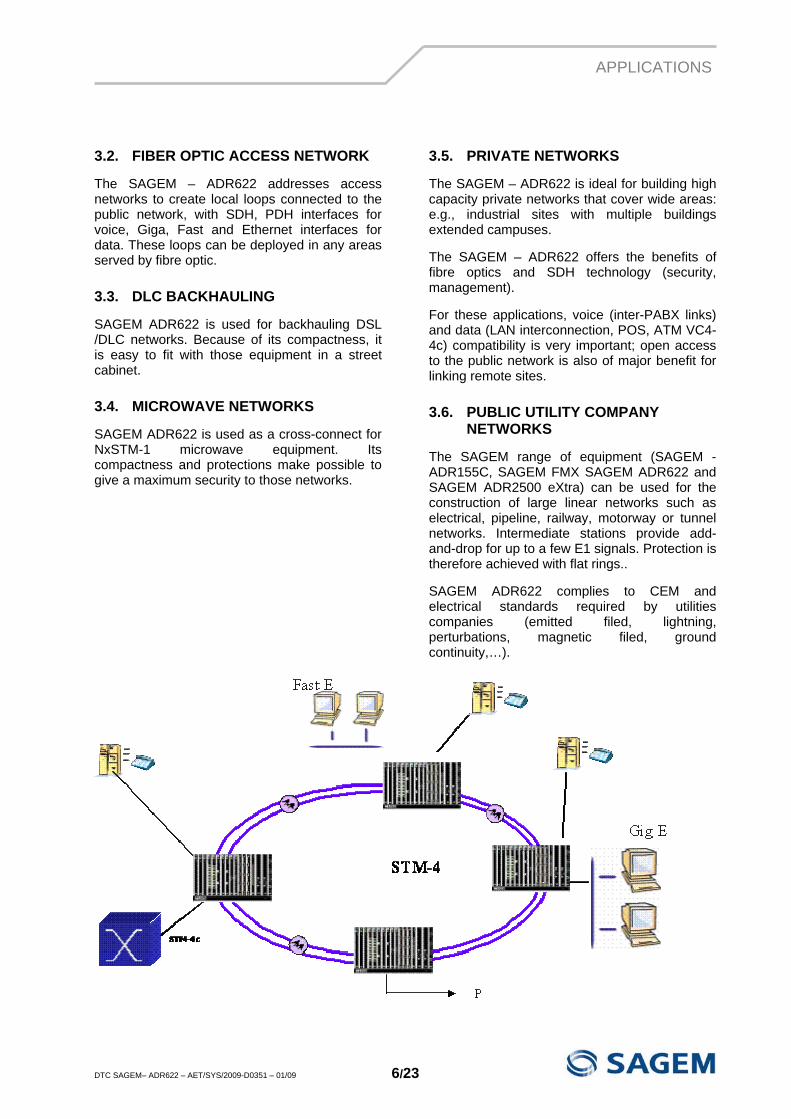
3.2. FIBER OPTIC ACCESS NETWORK
The SAGEM – ADR622 addresses access networks to create local loops connected to the public network, with SDH, PDH interfaces for voice, Giga, Fast and Ethernet interfaces for data. These loops can be deployed in any areas served by fibre optic.
3.3. DLC BACKHAULING
SAGEM ADR622 is used for backhauling DSL /DLC networks. Because of its compactness, it is easy to fit with those equipment in a street cabinet.
3.4. MICROWAVE NETWORKS
SAGEM ADR622 is used as a cross-connect for NxSTM-1 microwave equipment. Its compactness and protections make possible to give a maximum security to those networks.
3.5. PRIVATE NETWORKS
The SAGEM – ADR622 is ideal for building high capacity private networks that cover wide areas: e.g., industrial sites with multiple buildings extended campuses.
The SAGEM – ADR622 offers the benefits of fibre optics and SDH technology (security, management).
For these applications, voice (inter-PABX links) and data (LAN interconnection, POS, ATM VC4-4c) compatibility is very important; open access to the public network is also of major benefit for linking remote sites.
3.6. PUBLIC UTILITY COMPANY NETWORKS
The SAGEM range of equipment (SAGEM - ADR155C, SAGEM FMX SAGEM ADR622 and SAGEM ADR2500 eXtra) can be used for the construction of large linear networks such as electrical, pipeline, railway, motorway or tunnel networks. Intermediate stations provide add-and-drop for up to a few E1 signals. Protection is therefore achieved with flat rings..
SAGEM ADR622 complies to CEM and electrical standards required by utilities companies (emitted filed, lightning, perturbations, magnetic filed, ground continuity,…).
APPLICATIONS
DTC SAGEM– ADR622 – AET/SYS/2009-D0351 – 01/09 7/23
3.7. ETHERNET OVER SDH (EOS)
3.7.1. NEXT GENERATION SDH The goal of Next Generation SDH is to transport different type of services, both circuit mode and packet mode at the same time. By incorporating different technologies the aim is to keep the strong points and eliminate the weakness. The main points are:
- Multiservice transport based on SDH. SDH has efficient protection services as well as mature technology.
- The flexibility of the “trail” creation is carried by virtual concatenation and LCAS protocol. The virtual concatenation allows stacking of bandwidth of different VC12,VC3 or VC4 containers, in order to get the virtual container to an adjustable bandwidth according to the needs. The granularity respects 2 Mb/s, 50 Mb/s or 150 Mb/s. LCAS protocol insures the extremity synchronisation when there is an adjustable bandwidth, avoids the momentary interruption services.
- Choosing the best encapsulation mode for each services :
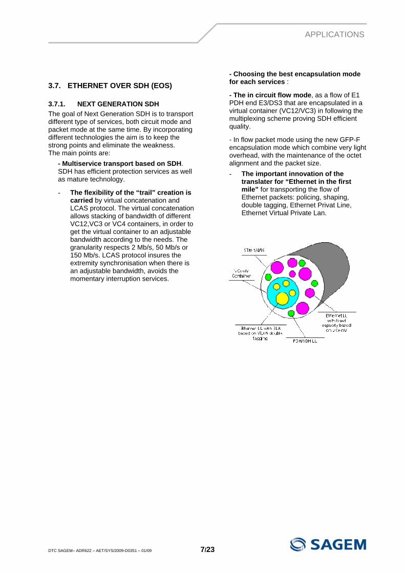
- The in circuit flow mode, as a flow of E1 PDH end E3/DS3 that are encapsulated in a virtual container (VC12/VC3) in following the multiplexing scheme proving SDH efficient quality.
- In flow packet mode using the new GFP-F encapsulation mode which combine very light overhead, with the maintenance of the octet alignment and the packet size. - The important innovation of the
translater for “Ethernet in the first mile” for transporting the flow of Ethernet packets: policing, shaping, double tagging, Ethernet Privat Line, Ethernet Virtual Private Lan.
APPLICATIONS
DTC SAGEM– ADR622 – AET/SYS/2009-D0351 – 01/09 8/23
3.7.2. SERVICES
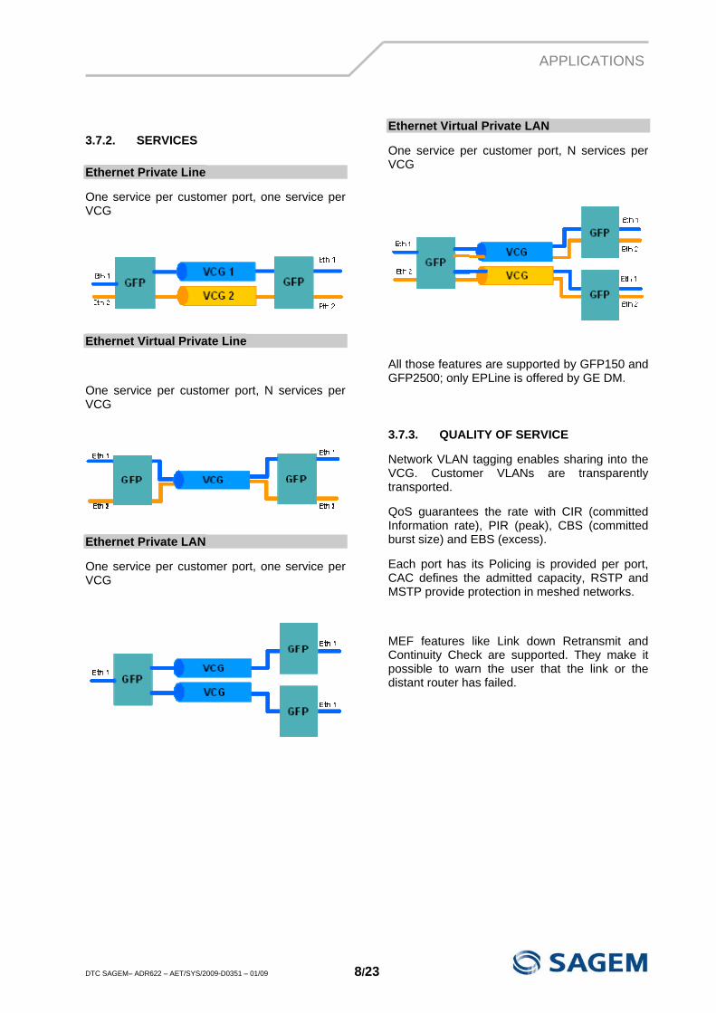
Ethernet Private Line
One service per customer port, one service per VCG
Ethernet Virtual Private Line
One service per customer port, N services per VCG
Ethernet Private LAN
One service per customer port, one service per VCG
Ethernet Virtual Private LAN
One service per customer port, N services per VCG
All those features are supported by GFP150 and GFP2500; only EPLine is offered by GE DM.
3.7.3. QUALITY OF SERVICE
Network VLAN tagging enables sharing into the VCG. Customer VLANs are transparently transported.
QoS guarantees the rate with CIR (committed Information rate), PIR (peak), CBS (committed burst size) and EBS (excess).
Each port has its Policing is provided per port, CAC defines the admitted capacity, RSTP and MSTP provide protection in meshed networks.
MEF features like Link down Retransmit and Continuity Check are supported. They make it possible to warn the user that the link or the distant router has failed.
FUNCTIONAL DESCRIPTION
DTC SAGEM– ADR622 – AET/SYS/2009-D0351 – 01/09 9/23
4. FUNCTIONAL DESCRIPTION
4.1. ARCHITECTURE
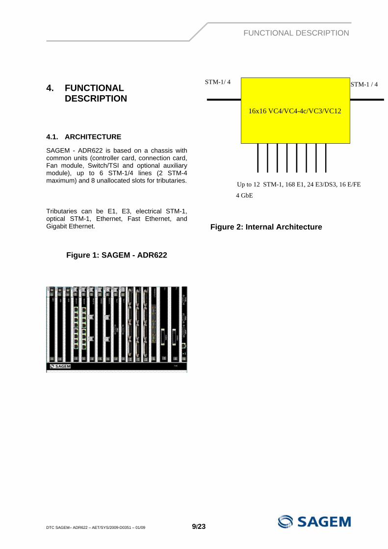
SAGEM - ADR622 is based on a chassis with common units (controller card, connection card, Fan module, Switch/TSI and optional auxiliary module), up to 6 STM-1/4 lines (2 STM-4 maximum) and 8 unallocated slots for tributaries.
Tributaries can be E1, E3, electrical STM-1, optical STM-1, Ethernet, Fast Ethernet, and Gigabit Ethernet.
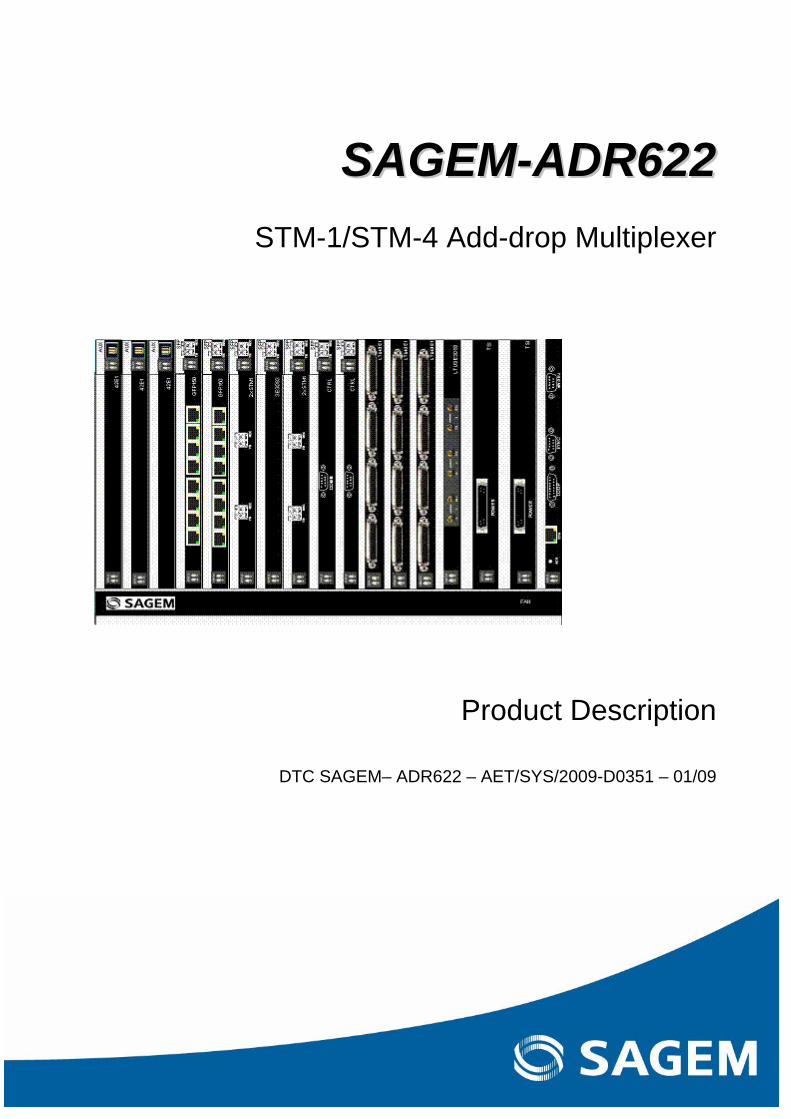
Figure 1: SAGEM - ADR622
Figure 2: Internal Architecture
STM-1/ 4 STM-1 / 4
16x16 VC4/VC4-4c/VC3/VC12
Up to 12 STM-1, 168 E1, 24 E3/DS3, 16 E/FE
4 GbE
FUNCTIONAL DESCRIPTION
DTC SAGEM– ADR622 – AET/SYS/2009-D0351 – 01/09 10/23
4.2. COMMON UNITS
4.2.1. FAN MODULE
The sub-rack includes a ventilation module.
The FAN Unit is removable, and can be changed without interrupting the traffic. It is made of 5 modules. When one fails, an alarm message appears informing the operator. However, the FAN is still providing enough cooling to the subrack.
4.2.2. TSI 16 VC4 HOLO UNIT
The Switch is the heart of the equipment; all cards are connected to this unit. It performs all the switching on 16x16 VC4 @VC12/VC3/VC4 and synchronisation. It also performs the protections (SNCP, MSP).
The Switch Unit can be protected in 1+1. It also performs the power supply feature.
4.2.3. CTRL622 UNIT (CONTROLER CARD)
The controller provides alarms and DCC processing for the whole equipment. It holds the configuration and management processes.
This card can be protected in 1+1
4.2.4. CCU622 UNIT (COMMON CONNECTION UNIT)
This unit is an interface unit for synchronisation and alarms.
4.3. AGGREGATES
4.3.1. STM-1/4 UNIT
This card is a small carrier card on which you plug STM-1 or STM-4 SFP modules (6 modules maximum, 2 STM-4 maximum).
4.3.2. SFP S-1.1
This SFP offer 0 to 12 dB at 1300 nm.
4.3.3. SFP L1.1
This SFP offer 10 to 28 dB at 1300 nm.
4.3.4. SFP L1.2
This SFP offer 10 to 28 dB at 1550 nm.
4.3.5. SFP S-4.1
This SFP offer 0 to 12 dB at 1300 nm.
4.3.6. SFP L-4.1
This SFP offer 10 to 24 dB at 1300 nm.
4.3.7. SFP L-4.2
This SFP offer 10 to 24 dB at 1550 nm.
4.3.8. SFP L-4.2+
This SFP offer 12 to 28 dB at 1550 nm.
FUNCTIONAL DESCRIPTION
DTC SAGEM– ADR622 – AET/SYS/2009-D0351 – 01/09 11/23
4.4. TRIBUTARIES
4.4.1. 2 STM-1 ELECTRICAL UNIT
This tributary card takes up to 2 STM-1 electrical signals and feeds them into the Switch. Protection can be made with STM-1 from the same or from another card.
4.4.2. 2XSTM-1 SFP
This unit accepts S1.1, L1.1, and L1.2 DDM SFP modules. It makes possible to offer the optical performance monitoring features like transmit power, received power, laser temperature, current and voltage. It also makes possible to mix S1.1 modules with L1.2 modules for instance, allowing an optimisation of configurations and spares.
4.4.3. GFP150 EXTRA UNIT The card has advanced features for the Ethernet and Fast Ethernet transport with a 950 Mb/s Switch capacity. • The card provides 8 accesses Ethernet
10/100Base-T. • The card can use up to 8 VC3-nV (1 < n < 2)
or VC12-nV (1 < n < 46). The total rate of the 8 channels reaches a maximum of 150 Mb/s.
• Increase or decrease of the channel capacity is carried out without traffic interruption according to LCAS protocol and VCAT function (Virtual Concatenation).
• Ethernet frame are encapsulated conforming GFP-F standard.
• The GFP150 card analyses the QoS of different Ethernet flow. The card offers OAM features.
• The card provides MSTP protocol to protect the Ethernet traffic and allow easy reconfigurations.
4.4.4. GE DM UNIT
The GE DM unit allows transport of Gigabit Ethernet on a point to point mode:
It uses GFP (Generic Format Protocol), LCAS (Link Adjustment Adaptation System) and virtual concatenation in order to split the signal into from 1 up to 7 VC4. The operator can therefore configure the capacity used in the SDH frame to transport the Gigabit interface. This traffic as it is
split into VC3s or VC4s can be protected as each VC4 in the SDH frame with SNCP.
One GE DM Unit accepts one or two SFP Gigabit Ethernet interfaces.
The card offers a “dual mode”, two capacities to the SDH Switch Card: a 600 Mbps capacity and a 2,5 Gbps capacity, allowing to transport the full bandwidth for the two Giga Ethernet ports.
4.4.5. GFP2500 UNIT The card has advanced features for Gigabit-Ethernet transport. : • It has a 4,5 Gb/s Layer 2 Ethernet witch. • The card provides 2 Giga Ethernet ports
with SFP modules and processes up to 22 VCG (VC3-nV, VC4-nV)
• It complies to VCAT, LCAS and GFP-F standards.
• On one Giga Ethernet interface, it aggregates traffic from GFP150 cards placed in ADR155c or ADR2500 eXtra.
• The card offers OAM features.
The card offers a “dual mode”, two capacities to the SDH Switch Card: a 600 Mbps capacity and a 2,5 Gbps capacity, allowing to transport the full bandwidth for the two Giga Ethernet ports.
4.4.6. 42 E1 UNIT WITH LTU
This tributary card connects 42 E1 with either a 120 ohms or a 75 ohms line termination unit. It can be protected in 1:4 mode as up to 4 cards can be fitted in the shelf in order to provide 168 E1s.
4.4.7. 42 E1 UNIT FRONT ACCESS
This tributary card connects 42 E1 front access. It cannot be protected and provides up to 168 E1s (4 cards).
4.4.8. 3 E3/DS3 UNIT WITH LTU
This tributary card connects 3 E3 or DS3 with a 75 ohms line termination unit. It can be protected in 1:4 mode as up to 4 cards can be fitted in the shelf in order to provide 12 E3/DS3..
4.4.9. 3 E3/DS3 UNIT FRONT ACCESS
This tributary card connects 3 E3 or DS3 front access. It cannot be protected.
FUNCTIONAL DESCRIPTION
DTC SAGEM– ADR622 – AET/SYS/2009-D0351 – 01/09 12/23
4.5. PROTECTION
All the main protection modes are possible with the SAGEM – ADR622:
• STM-n MSP 1+1 (for STM-1 and STM-4 in case of point to point)
• VC12, VC3 or VC-4 path protection (SNC-P)
4.5.1. MSP PROTECTION 1+1
STM-n line protection is obtained by doubling the fibber optic cable and the STM-n interface module (1+1):
transmission over two channels, main and backup Receiving-end selection from either channel.
There is automatic switchover to the protection link in accordance with the criteria described in ITU-T recommendation G.823. There is no interruption to the orderwire and data flows with MSP 1+1 protection.
Protection switching is initiated upon:
• a line fault, • STM-n interface module fault, • an operator command.
When detected on the main channel, the following fault conditions initiate MSP protection:
SF (Signal Fail): logic ORing of: − STM-n incoming signal loss (LOS STM-n) − STM-n loss of frame alignment (LOF
STM-n) − STM-n multiplex section AIS detection
(MS-AIS) − Byte B2 excessive bit error rate (EBER-
B2) − STM-n interface module absence.
SD (Signal Degrade): B2 bit error rate greater than configurable threshold.
The SF and SD indications are processed and filtered (fault persistency filter with configurable time persistency). This activates the K1/K2 protocol described in ITU-T recommendation G.783 to initiate the protection mechanism.
4.5.2. (SNC-P) 1+1 PATH PROTECTION
SNC-P path protection is used in ring topologies and consists in using the two sides of the ring: one for the normal path, the other for the backup path.
When detected on the main channel, the following fault conditions initiate a switch:
SF (Signal Fail): logic « OR » of: − AIS detection at path termination (LP-
AIS) − Byte B3 excessive bit error rate (EBER-
B3) SD (Signal Degrade):
B3 bit error rate greater than configurable threshold.
The SF and SD indications are processed and filtered (fault persistency filter with configurable time persistency).
The switching process lasts approximately 50 ms after confirmation of the originating fault, and the switch status is maintained until tributary signal restoration.
FUNCTIONAL DESCRIPTION
DTC SAGEM– ADR622 – AET/SYS/2009-D0351 – 01/09 13/23
4.6. SYNCHRONISATION
The SAGEM – ADR622:
uses its own timing source to synchronise transmission via the STM-n interfaces, can provide the synchronisation for other equipment, can be synchronised to an internal or an external source.
Synchronisation is performed by the Switch card and therefore can be protected in 1+1.
4.6.1. SYNCHRONIZATION SOURCES
The SAGEM – ADR622 may be synchronised to the following alternative timing sources:
• Tributary or aggregate STM-n signals, • Tributary 2Mbit/s • ITU-T G.703-compliant 2048 kHz external
clock signal, • the internal local oscillator (+/- 4.6 ppm). • Enabling the operator to plan the
synchronisation through all aggregates, all tributaries and external synchronisation of its network.
4.6.2. AUTOMATIC MODE
In the event of a failure of the active sync source, synchronisation switches automatically to one of various prioritised standby sync sources. This switching mechanism can be reversible. Synchronisation information is carried and processed by S1 byte.
4.6.3. MANUAL MODE
It is possible to force-manually to one of the available sources.
4.7. OVERHEAD
4.7.1. OVERHEAD BYTE PROCESSOR
Path overhead (POH) and section overhead (SOH) bytes, which are added to and dropped from the STM-1 frame, carry various items of supervisory information relative to the STM-1 links:
• frame alignment bytes, • parity check data, • engineering orderwires and digital service
channels interchanged by both ends of a network.
4.7.2. ENGINEERING ORDERWIRES AND DIGITAL SERVICE CHANNELS
A digital channel (E1 or F1 overhead byte) in the STM-n frame is reserved for transport of a digital engineering orderwire (EOW). Digital service channel protection is as with 1+1 line protection. The E1 and F1 bytes are available over a SubD/HE5 connector on the AUX module front panel. One AUX module is needed per direction. To have a voice signal EOW, it is necessary to have an external mechanism (SAGEM-EOW300) which adapts the 64 kbit/s digital signal of the E1 and F1 interfaces.
OPTICAL ENGINEERING
DTC SAGEM– ADR622 – AET/SYS/2009-D0351 – 01/09 14/23
5. OPTICAL ENGINEERING
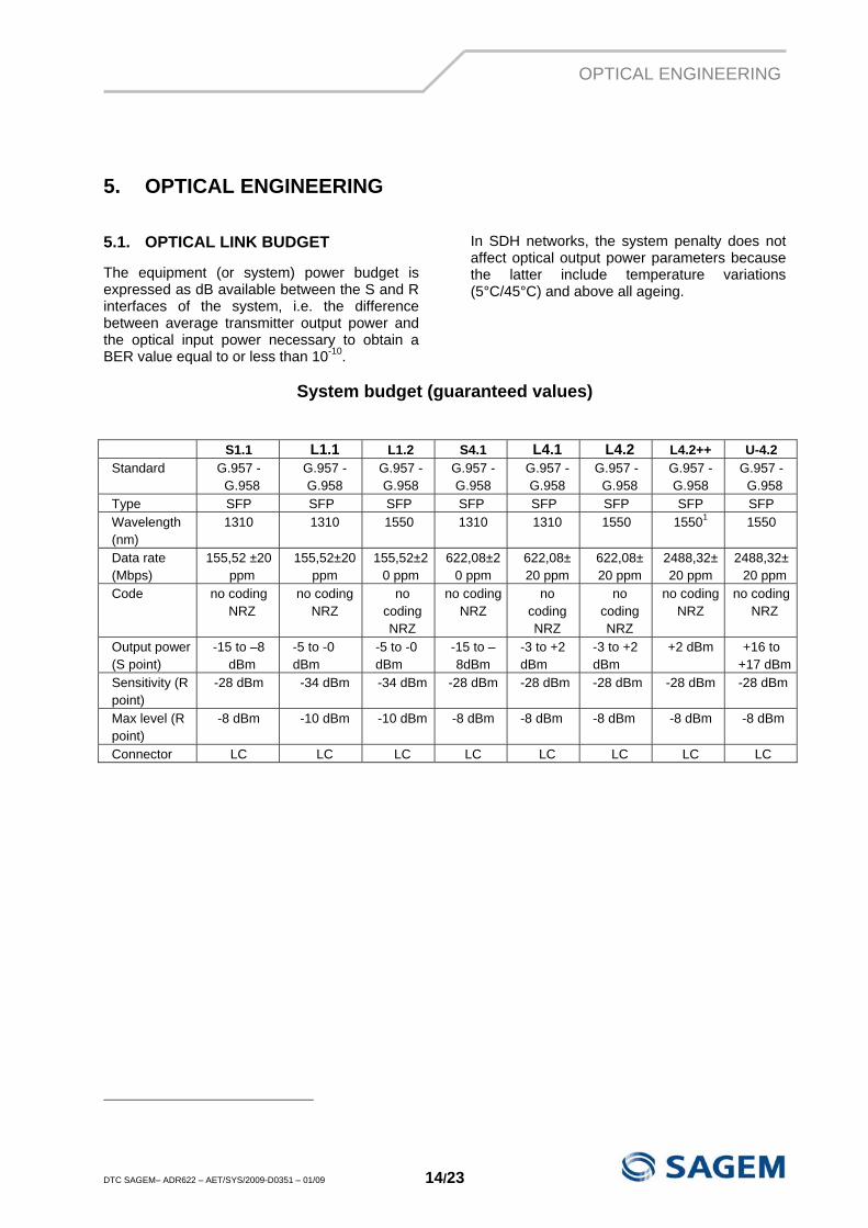
5.1. OPTICAL LINK BUDGET
The equipment (or system) power budget is expressed as dB available between the S and R interfaces of the system, i.e. the difference between average transmitter output power and the optical input power necessary to obtain a BER value equal to or less than 10-10.
In SDH networks, the system penalty does not affect optical output power parameters because the latter include temperature variations (5°C/45°C) and above all ageing.
System budget (guaranteed values)
S1.1 L1.1 L1.2 S4.1 L4.1 L4.2 L4.2++ U-4.2 Standard G.957 -
G.958 G.957 - G.958
G.957 - G.958
G.957 - G.958
G.957 - G.958
G.957 - G.958
G.957 - G.958
G.957 - G.958
Type SFP SFP SFP SFP SFP SFP SFP SFP Wavelength (nm)
1310 1310 1550 1310 1310 1550 15501 1550
Data rate (Mbps)
155,52 ±20 ppm
155,52±20 ppm
155,52±20 ppm
622,08±20 ppm
622,08±20 ppm
622,08±20 ppm
2488,32±20 ppm
2488,32±20 ppm
Code no coding NRZ
no coding NRZ
no coding NRZ
no coding NRZ
no coding NRZ
no coding NRZ
no coding NRZ
no coding NRZ
Output power (S point)
-15 to –8 dBm
-5 to -0 dBm
-5 to -0 dBm
-15 to –8dBm
-3 to +2 dBm
-3 to +2 dBm
+2 dBm +16 to +17 dBm
Sensitivity (R point)
-28 dBm -34 dBm -34 dBm -28 dBm -28 dBm -28 dBm -28 dBm -28 dBm
Max level (R point)
-8 dBm -10 dBm -10 dBm -8 dBm -8 dBm -8 dBm -8 dBm -8 dBm
Connector LC LC LC LC LC LC LC LC
INSTALLATION
DTC SAGEM– ADR622 – AET/SYS/2009-D0351 – 01/09 15/23
6. INSTALLATION
6.1. MECHANICAL INSTALLATION
The same SAGEM – ADR622 unit can be installed in a 19’’ or ETSI rack, 300 mm deep.
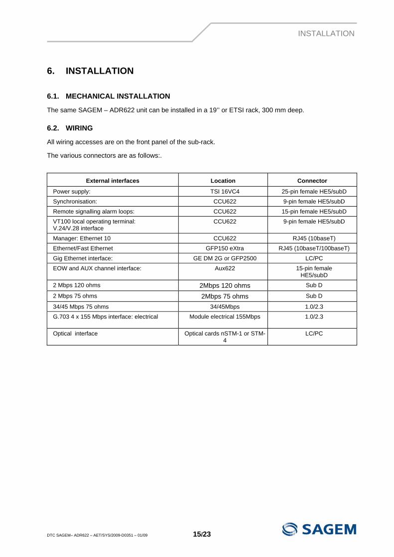
6.2. WIRING
All wiring accesses are on the front panel of the sub-rack.
The various connectors are as follows:.
External interfaces Location Connector
Power supply: TSI 16VC4 25-pin female HE5/subD
Synchronisation: CCU622 9-pin female HE5/subD
Remote signalling alarm loops: CCU622 15-pin female HE5/subD
VT100 local operating terminal: V.24/V.28 interface
CCU622 9-pin female HE5/subD
Manager: Ethernet 10 CCU622 RJ45 (10baseT)
Ethernet/Fast Ethernet GFP150 eXtra RJ45 (10baseT/100baseT)
Gig Ethernet interface: GE DM 2G or GFP2500 LC/PC
EOW and AUX channel interface: Aux622 15-pin female HE5/subD
2 Mbps 120 ohms 2Mbps 120 ohms Sub D
2 Mbps 75 ohms 2Mbps 75 ohms Sub D
34/45 Mbps 75 ohms 34/45Mbps 1.0/2.3
G.703 4 x 155 Mbps interface: electrical Module electrical 155Mbps
1.0/2.3
Optical interface Optical cards nSTM-1 or STM-4
LC/PC
SUPERVISION/MAINTENANCE
DTC SAGEM– ADR622 – AET/SYS/2009-D0351 – 01/09 16/23
7. SUPERVISION/MAINTENANCE
7.1. SUPERVISION
7.1.1. LOCAL SUPERVISION
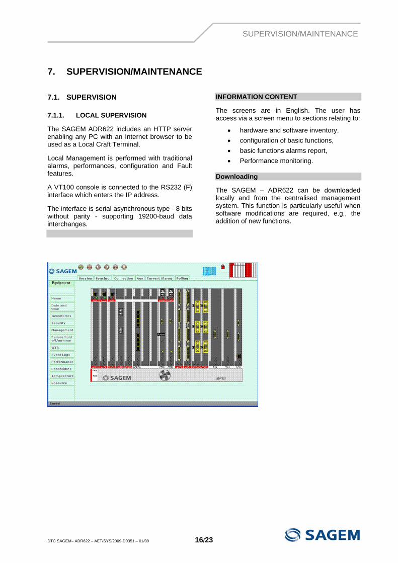
The SAGEM ADR622 includes an HTTP server enabling any PC with an Internet browser to be used as a Local Craft Terminal.
Local Management is performed with traditional alarms, performances, configuration and Fault features.
A VT100 console is connected to the RS232 (F) interface which enters the IP address.
The interface is serial asynchronous type - 8 bits without parity - supporting 19200-baud data interchanges.
INFORMATION CONTENT
The screens are in English. The user has access via a screen menu to sections relating to:
• hardware and software inventory, • configuration of basic functions, • basic functions alarms report, • Performance monitoring.
Downloading
The SAGEM – ADR622 can be downloaded locally and from the centralised management system. This function is particularly useful when software modifications are required, e.g., the addition of new functions.
SUPERVISION/MAINTENANCE
DTC SAGEM– ADR622 – AET/SYS/2009-D0351 – 01/09 17/23
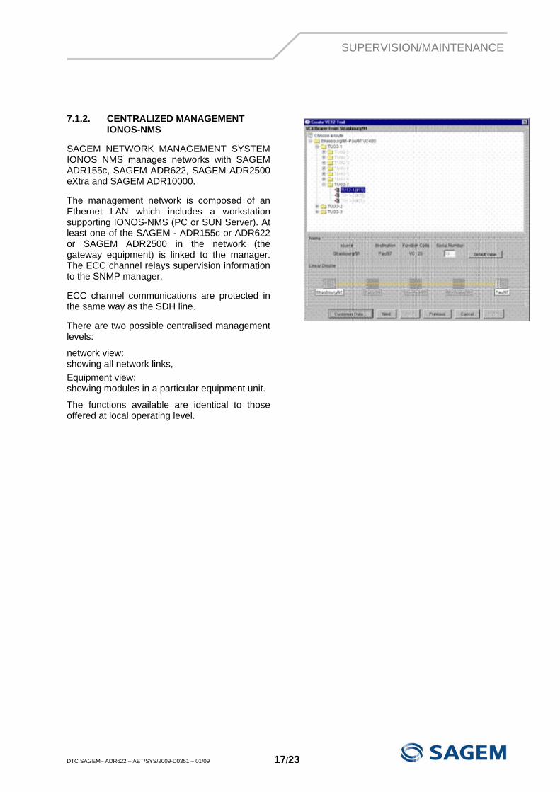
7.1.2. CENTRALIZED MANAGEMENT
IONOS-NMS
SAGEM NETWORK MANAGEMENT SYSTEM IONOS NMS manages networks with SAGEM ADR155c, SAGEM ADR622, SAGEM ADR2500 eXtra and SAGEM ADR10000.
The management network is composed of an Ethernet LAN which includes a workstation supporting IONOS-NMS (PC or SUN Server). At least one of the SAGEM - ADR155c or ADR622 or SAGEM ADR2500 in the network (the gateway equipment) is linked to the manager. The ECC channel relays supervision information to the SNMP manager.
ECC channel communications are protected in the same way as the SDH line.
There are two possible centralised management levels:
network view: showing all network links, Equipment view: showing modules in a particular equipment unit.
The functions available are identical to those offered at local operating level.
SUPERVISION/MAINTENANCE
DTC SAGEM– ADR622 – AET/SYS/2009-D0351 – 01/09 18/23
7.2. MAINTENANCE
7.2.1. ALARMS
The SAGEM – ADR622 System provides operators with various fault detection and faulty card isolation facilities for maintenance purposes.
On the SAGEM – ADR622 equipment: • Color-coded LEDs on each card, • Two network management relay contact
alarms. • Via the NMS: • current alarms status, • alarm and performance event logs, • network, link or equipment level view.
The SAGEM – ADR622 has four remote signalling inputs ("TSIG") for external equipment alarm notification.
7.2.2. SELF-TESTS
The SAGEM – ADR622 software carries out software self-tests:
at start-up, periodically, upon insertion of a new module.
These routines are transparent to operations and do not affect service.
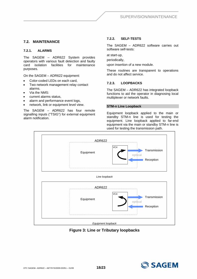
7.2.3. LOOPBACKS
The SAGEM – ADR622 has integrated loopback functions to aid the operator in diagnosing local multiplexer or network faults.
STM-n Line Loopback
Equipment loopback applied to the main or standby STM-n line is used for testing the equipment. Line loopback applied to far-end equipment via the main or standby STM-n line is used for testing the transmission path.
Equipment
VC4Transmission
Receptionoptical
ADR622
Line loopback
Equipment
VC4Transmission
Receptionoptical
ADR622
Equipment loopback
Figure 3: Line or Tributary loopbacks
SPECIFICATIONS
DTC SAGEM– ADR622 – AET/SYS/2009-D0351 – 01/09 19/23
8. SPECIFICATIONS
8.1. ELECTRICAL AND OPTICAL SPECIFICATIONS
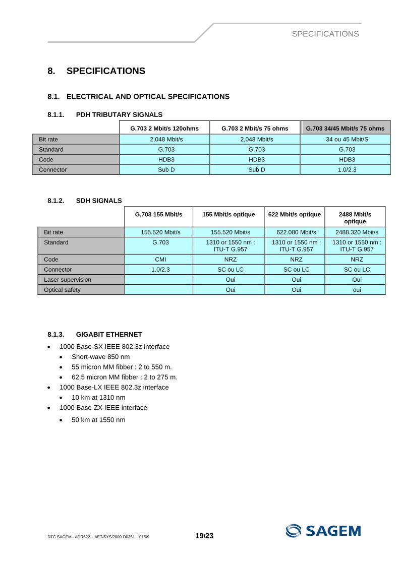
8.1.1. PDH TRIBUTARY SIGNALS
G.703 2 Mbit/s 120ohms G.703 2 Mbit/s 75 ohms G.703 34/45 Mbit/s 75 ohms
Bit rate 2,048 Mbit/s 2,048 Mbit/s 34 ou 45 Mbit/S
Standard G.703 G.703 G.703
Code HDB3 HDB3 HDB3
Connector Sub D Sub D 1.0/2.3
8.1.2. SDH SIGNALS
G.703 155 Mbit/s 155 Mbit/s optique 622 Mbit/s optique 2488 Mbit/s optique
Bit rate 155.520 Mbit/s 155.520 Mbit/s 622.080 Mbit/s 2488.320 Mbit/s
Standard G.703 1310 or 1550 nm : ITU-T G.957
1310 or 1550 nm : ITU-T G.957
1310 or 1550 nm : ITU-T G.957
Code CMI NRZ NRZ NRZ
Connector 1.0/2.3 SC ou LC SC ou LC SC ou LC
Laser supervision Oui Oui Oui
Optical safety Oui Oui oui
8.1.3. GIGABIT ETHERNET
• 1000 Base-SX IEEE 802.3z interface • Short-wave 850 nm • 55 micron MM fibber : 2 to 550 m. • 62.5 micron MM fibber : 2 to 275 m.
• 1000 Base-LX IEEE 802.3z interface • 10 km at 1310 nm
• 1000 Base-ZX IEEE interface
• 50 km at 1550 nm
SPECIFICATIONS
DTC SAGEM– ADR622 – AET/SYS/2009-D0351 – 01/09 20/23
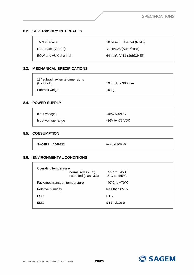
8.2. SUPERVISORY INTERFACES
TMN interface 10 base T Ethernet (RJ45)
F Interface (VT100): V.24/V.28 (SubD/HE5)
EOW and AUX channel 64 kbit/s V.11 (SubD/HE5)
8.3. MECHANICAL SPECIFICATIONS
19" subrack external dimensions (L x H x D) 19" x 6U x 300 mm
Subrack weight 10 kg
8.4. POWER SUPPLY
Input voltage: -48V/-60VDC
Input voltage range -36V to -72 VDC
8.5. CONSUMPTION
SAGEM – ADR622 typical 100 W
8.6. ENVIRONMENTAL CONDITIONS
Operating temperature normal (class 3.2) +5°C to +45°C extended (class 3.3) -5°C to +55°C
Packaged/transport temperature -40°C to +70°C
Relative humidity less than 85 %
ESD ETSI
EMC ETSI class B
SPECIFICATIONS
DTC SAGEM– ADR622 – AET/SYS/2009-D0351 – 01/09 21/23
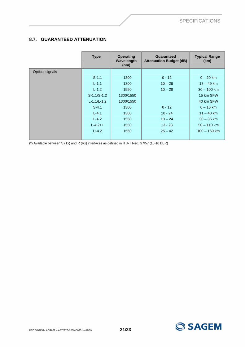
8.7. GUARANTEED ATTENUATION
Type Operating Wavelength
(nm)
Guaranteed Attenuation Budget (dB)
Typical Range (km)
Optical signals S-1.1 L-1.1 L-1.2
S-1.1/S-1.2 L-1.1/L-1.2
S-4.1 L-4.1 L-4.2
L-4.2++ U-4.2
1300 1300 1550
1300/1550 1300/1550
1300 1300 1550 1550 1550
0 - 12
10 – 28 10 – 28
0 - 12 10 - 24 10 – 24 13 - 28 25 – 42
0 – 20 km 18 – 49 km
30 – 100 km 15 km SFW 40 km SFW 0 – 16 km 11 – 40 km 30 – 86 km
50 – 110 km 100 – 160 km
(*) Available between S (Tx) and R (Rx) interfaces as defined in ITU-T Rec. G.957 (10-10 BER)

Le Ponant de Paris
27, rue Leblanc BP 30070
75722 PARIS CEDEX 15 France
Tel : +33 1 58 11 77 00 www.sagem-communications.com