DT Family - Farnell · DT Family Part Numbering System DT Series Overview Deutsch’s DT Series...
16
DT Family 17 Contents DT Family Overview 18 DTV Series 28 Part Numbering System 18 DTMH Series 29 Dimensions 19 DTMN Series 30 Configurations 20 How To Instructions 31 Required Components 21-22 Special Modifications 22-23 Accessories 24-27
Transcript of DT Family - Farnell · DT Family Part Numbering System DT Series Overview Deutsch’s DT Series...
DT Family
17
Contents
DT Family Overview 18 DTV Series 28
Part Numbering System 18 DTMH Series 29
Dimensions 19 DTMN Series 30
Confi gurations 20 How To Instructions 31
Required Components 21-22
Special Modifi cations 22-23
Accessories 24-27
A STEP AHEAD
18
DT Family
DT Family Overview
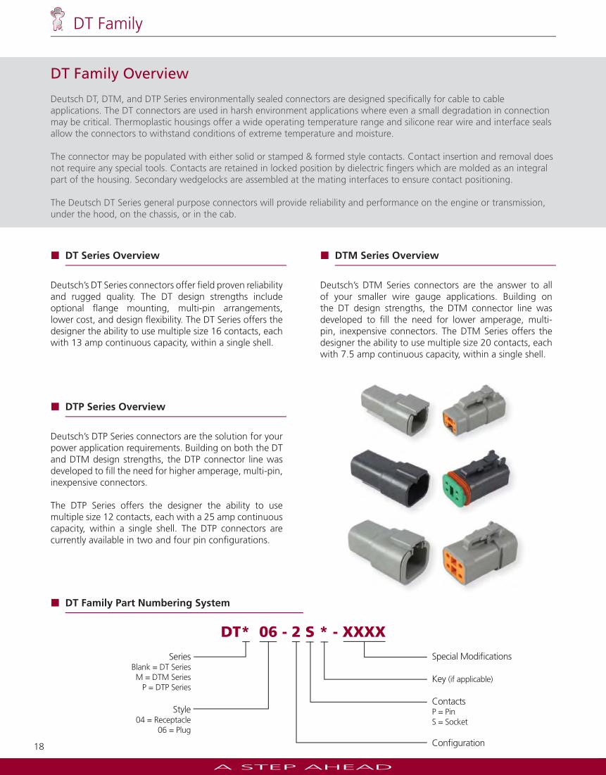
Deutsch DT, DTM, and DTP Series environmentally sealed connectors are designed specifi cally for cable to cable applications. The DT connectors are used in harsh environment applications where even a small degradation in connection may be critical. Thermoplastic housings offer a wide operating temperature range and silicone rear wire and interface seals allow the connectors to withstand conditions of extreme temperature and moisture.
The connector may be populated with either solid or stamped & formed style contacts. Contact insertion and removal does not require any special tools. Contacts are retained in locked position by dielectric fi ngers which are molded as an integral part of the housing. Secondary wedgelocks are assembled at the mating interfaces to ensure contact positioning.
The Deutsch DT Series general purpose connectors will provide reliability and performance on the engine or transmission, under the hood, on the chassis, or in the cab.
DT* 06 - 2 S * - XXXX
SeriesBlank = DT SeriesM = DTM Series
P = DTP Series
Style04 = Receptacle
06 = Plug
Special Modifi cations
Key (if applicable)
ContactsP = Pin S = Socket
Confi guration
DT Family Part Numbering System
DT Series Overview
Deutsch’s DT Series connectors offer fi eld proven reliability and rugged quality. The DT design strengths include optional fl ange mounting, multi-pin arrangements, lower cost, and design fl exibility. The DT Series offers the designer the ability to use multiple size 16 contacts, each with 13 amp continuous capacity, within a single shell.
DTM Series Overview
Deutsch’s DTM Series connectors are the answer to all of your smaller wire gauge applications. Building on the DT design strengths, the DTM connector line was developed to fi ll the need for lower amperage, multi-pin, inexpensive connectors. The DTM Series offers the designer the ability to use multiple size 20 contacts, each with 7.5 amp continuous capacity, within a single shell.
DTP Series Overview
Deutsch’s DTP Series connectors are the solution for your power application requirements. Building on both the DT and DTM design strengths, the DTP connector line was developed to fi ll the need for higher amperage, multi-pin, inexpensive connectors.
The DTP Series offers the designer the ability to use multiple size 12 contacts, each with a 25 amp continuous capacity, within a single shell. The DTP connectors are currently available in two and four pin confi gurations.
A STEP AHEAD
19
DT Family
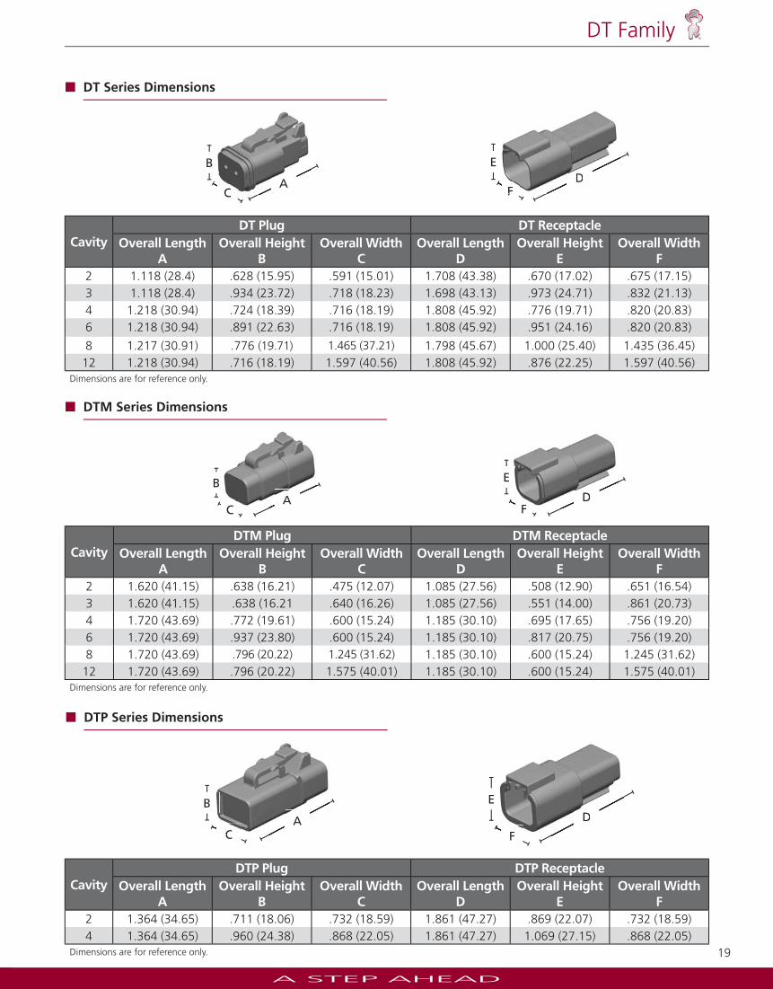
CavityDT Plug DT Receptacle
Overall LengthA
Overall HeightB
Overall WidthC
Overall LengthD
Overall HeightE
Overall WidthF
2 1.118 (28.4) .628 (15.95) .591 (15.01) 1.708 (43.38) .670 (17.02) .675 (17.15)3 1.118 (28.4) .934 (23.72) .718 (18.23) 1.698 (43.13) .973 (24.71) .832 (21.13)4 1.218 (30.94) .724 (18.39) .716 (18.19) 1.808 (45.92) .776 (19.71) .820 (20.83)6 1.218 (30.94) .891 (22.63) .716 (18.19) 1.808 (45.92) .951 (24.16) .820 (20.83)
8 1.217 (30.91) .776 (19.71) 1.465 (37.21) 1.798 (45.67) 1.000 (25.40) 1.435 (36.45)12 1.218 (30.94) .716 (18.19) 1.597 (40.56) 1.808 (45.92) .876 (22.25) 1.597 (40.56)
Dimensions are for reference only.
DT Series Dimensions
FD
E
FDA
C
B
AC
CavityDTP Plug DTP Receptacle
Overall LengthA
Overall HeightB
Overall WidthC
Overall LengthD
Overall HeightE
Overall WidthF
2 1.364 (34.65) .711 (18.06) .732 (18.59) 1.861 (47.27) .869 (22.07) .732 (18.59)4 1.364 (34.65) .960 (24.38) .868 (22.05) 1.861 (47.27) 1.069 (27.15) .868 (22.05)
Dimensions are for reference only.
DTP Series Dimensions
F
DE
F
DAC
BA
C
CavityDTM Plug DTM Receptacle
Overall LengthA
Overall HeightB
Overall WidthC
Overall LengthD
Overall HeightE
Overall WidthF
2 1.620 (41.15) .638 (16.21) .475 (12.07) 1.085 (27.56) .508 (12.90) .651 (16.54)3 1.620 (41.15) .638 (16.21 .640 (16.26) 1.085 (27.56) .551 (14.00) .861 (20.73)4 1.720 (43.69) .772 (19.61) .600 (15.24) 1.185 (30.10) .695 (17.65) .756 (19.20)6 1.720 (43.69) .937 (23.80) .600 (15.24) 1.185 (30.10) .817 (20.75) .756 (19.20)8 1.720 (43.69) .796 (20.22) 1.245 (31.62) 1.185 (30.10) .600 (15.24) 1.245 (31.62)
12 1.720 (43.69) .796 (20.22) 1.575 (40.01) 1.185 (30.10) .600 (15.24) 1.575 (40.01)Dimensions are for reference only.
DTM Series Dimensions
F
E
DF
DAC
BA
C
A STEP AHEAD
20
DT Family
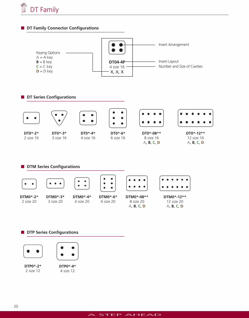
DTP0*-2*2 size 12
DTP0*-4*4 size 12
DT04-4P4 size 16X, X, X
Keying OptionsA = A keyB = B keyC = C keyD = D key
Insert Arrangement
Insert LayoutNumber and Size of Cavities
DT Family Connector Confi gurations
DTM0*-08**8 size 20A, B, C, D
DTM0*-12**12 size 20A, B, C, D
DTM0*-2*2 size 20
DTM0*-3*3 size 20
DTM0*-4*4 size 20
DTM0*-6*6 size 20
DTM Series Confi gurations
DT0*-08**8 size 16A, B, C, D
DT0*-12**12 size 16A, B, C, D
DT0*-6*6 size 16
DT0*-2*2 size 16
DT0*-3*3 size 16
DT0*-4*4 size 16
DT Series Confi gurations
DTP Series Confi gurations
A STEP AHEAD
21
DT Family
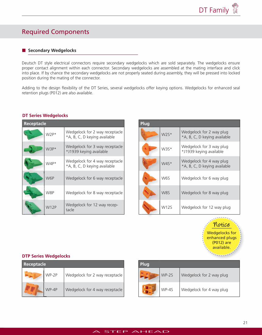
DTP Series Wedgelocks
Receptacle Plug
WP-2P Wedgelock for 2 way receptacle WP-2S Wedgelock for 2 way plug
WP-4P Wedgelock for 4 way receptacle WP-4S Wedgelock for 4 way plug
W
W
DT Series Wedgelocks
Receptacle Plug
W2P*Wedgelock for 2 way receptacle*A, B, C, D keying available
W2S*Wedgelock for 2 way plug*A, B, C, D keying available
W3P*Wedgelock for 3 way receptacle*J1939 keying available
W3S*Wedgelock for 3 way plug*J1939 keying available
W4P*Wedgelock for 4 way receptacle*A, B, C, D keying available
W4S*Wedgelock for 4 way plug*A, B, C, D keying available
W6P Wedgelock for 6 way receptacle W6S Wedgelock for 6 way plug
W8P Wedgelock for 8 way receptacle W8S Wedgelock for 8 way plug
W12PWedgelock for 12 way recep-tacle
W12S Wedgelock for 12 way plug
W W
W
W
W
W
Required Components
Secondary Wedgelocks
Deutsch DT style electrical connectors require secondary wedgelocks which are sold separately. The wedgelocks ensure proper contact alignment within each connector. Secondary wedgelocks are assembled at the mating interface and click into place. If by chance the secondary wedgelocks are not properly seated during assembly, they will be pressed into locked position during the mating of the connector.
Adding to the design fl exibility of the DT Series, several wedgelocks offer keying options. Wedgelocks for enhanced seal retention plugs (P012) are also available.
Jiffy Splicesaccept one pin and one
socket.
NoteJiffy Splicesaccept one pin and one
socket.
NoteNote
Wedgelocks for enhanced plugs
(P012) areavailable.
NoticeNotice
A STEP AHEAD
22
DT Family
Special Modifi cations
The DT Series connectors offer several modifi cations to enhance the design fl exibility and meet application specifi c needs. Options include enhanced seal retention, fl anges, and connector body color just to mention a few. By combining the DT Series connectors with the available modifi cations and accessories, the design possibilities are immense.
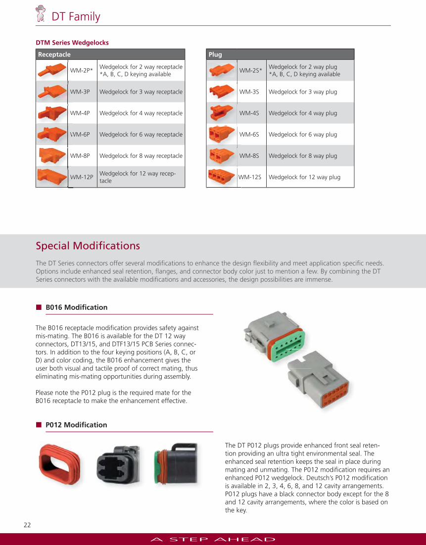
DTM Series Wedgelocks
Receptacle Plug
WM-2P*Wedgelock for 2 way receptacle*A, B, C, D keying available
WM-2S*Wedgelock for 2 way plug*A, B, C, D keying available
WM-3P Wedgelock for 3 way receptacle WM-3S Wedgelock for 3 way plug
WM-4P Wedgelock for 4 way receptacle WM-4S Wedgelock for 4 way plug
WM-6P Wedgelock for 6 way receptacle WM-6S Wedgelock for 6 way plug
WM-8P Wedgelock for 8 way receptacle WM-8S Wedgelock for 8 way plug
WM-12PWedgelock for 12 way recep-tacle
WM-12S Wedgelock for 12 way plugW W
W W
W W
W
W W
W W
B016 Modifi cation
The B016 receptacle modifi cation provides safety against mis-mating. The B016 is available for the DT 12 way connectors, DT13/15, and DTF13/15 PCB Series connec-tors. In addition to the four keying positions (A, B, C, or D) and color coding, the B016 enhancement gives the user both visual and tactile proof of correct mating, thus eliminating mis-mating opportunities during assembly.
Please note the P012 plug is the required mate for the B016 receptacle to make the enhancement effective.
P012 Modifi cation
The DT P012 plugs provide enhanced front seal reten-tion providing an ultra tight environmental seal. The enhanced seal retention keeps the seal in place during mating and unmating. The P012 modifi cation requires an enhanced P012 wedgelock. Deutsch’s P012 modifi cation is available in 2, 3, 4, 6, 8, and 12 cavity arrangements. P012 plugs have a black connector body except for the 8 and 12 cavity arrangements, where the color is based on the key.
A STEP AHEAD
23
DT Family
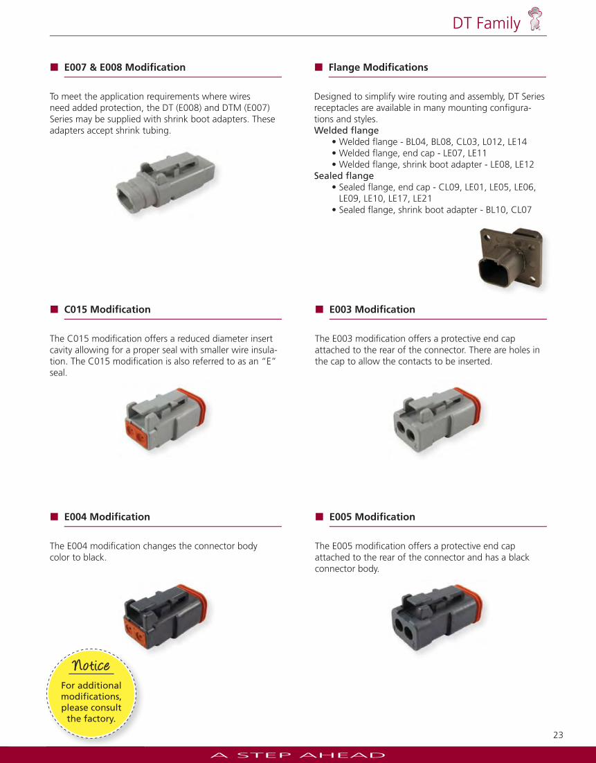
E007 & E008 Modifi cation
To meet the application requirements where wires need added protection, the DT (E008) and DTM (E007) Series may be supplied with shrink boot adapters. These adapters accept shrink tubing.
C015 Modifi cation
The C015 modifi cation offers a reduced diameter insert cavity allowing for a proper seal with smaller wire insula-tion. The C015 modifi cation is also referred to as an “ E” seal.
E004 Modifi cation
The E004 modifi cation changes the connector body color to black.
Flange Modifi cations
Designed to simplify wire routing and assembly, DT Series receptacles are available in many mounting confi gura-tions and styles.Welded fl ange
• Welded flange - BL04, BL08, CL03, L012, LE14• Welded flange, end cap - LE07, LE11• Welded flange, shrink boot adapter - LE08, LE12
Sealed fl ange• Sealed flange, end cap - CL09, LE01, LE05, LE06,
LE09, LE10, LE17, LE21• Sealed flange, shrink boot adapter - BL10, CL07
E003 Modifi cation
The E003 modifi cation offers a protective end cap attached to the rear of the connector. There are holes in the cap to allow the contacts to be inserted.
E005 Modifi cation
The E005 modifi cation offers a protective end cap attached to the rear of the connector and has a black connector body.
Jiffy Splicesaccept one pin and one
socket.
NoteJiffy Splicesaccept one pin and one
socket.
NoteNote
For additional modifi cations, please consult
the factory.
NoticeNotice
A STEP AHEAD
24
DT Family
LA D D In d u st rie s
Avail
able through
L A D D In d u st rie s
Avail
able through
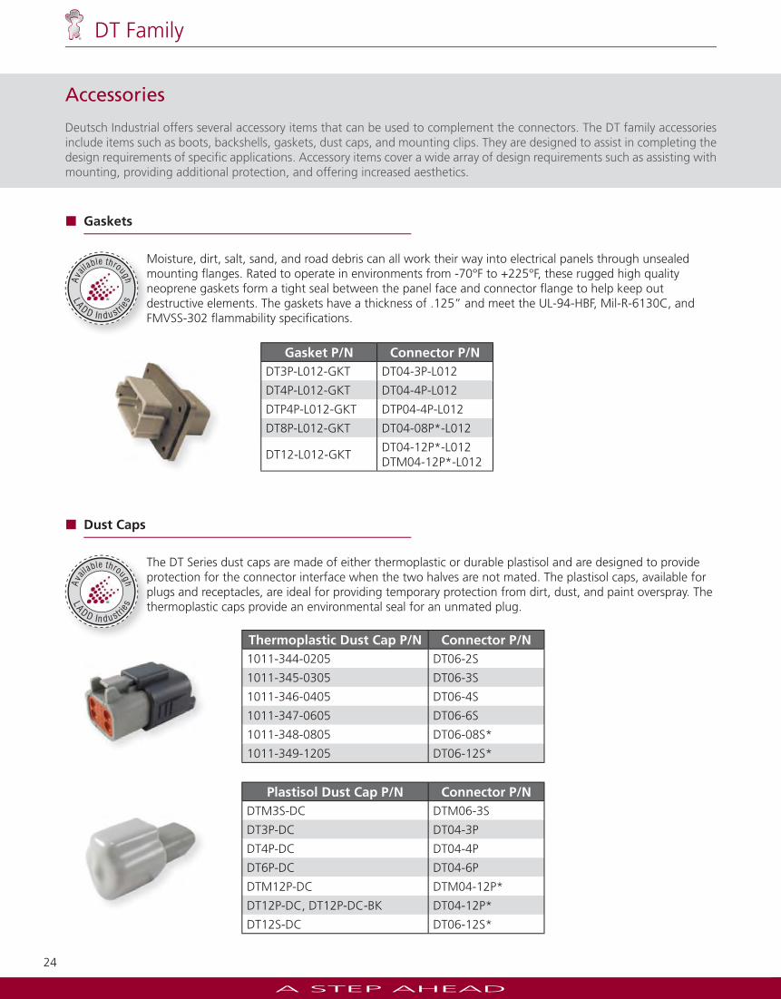
Accessories
Deutsch Industrial offers several accessory items that can be used to complement the connectors. The DT family accessories include items such as boots, backshells, gaskets, dust caps, and mounting clips. They are designed to assist in completing the design requirements of specifi c applications. Accessory items cover a wide array of design requirements such as assisting with mounting, providing additional protection, and offering increased aesthetics.
Gasket P/N Connector P/NDT3P-L012-GKT DT04-3P-L012
DT4P-L012-GKT DT04-4P-L012
DTP4P-L012-GKT DTP04-4P-L012
DT8P-L012-GKT DT04-08P*-L012
DT12-L012-GKTDT04-12P*-L012DTM04-12P*-L012
Gaskets
Moisture, dirt, salt, sand, and road debris can all work their way into electrical panels through unsealed mounting fl anges. Rated to operate in environments from -70°F to +225°F, these rugged high quality neoprene gaskets form a tight seal between the panel face and connector fl ange to help keep out destructive elements. The gaskets have a thickness of .125” and meet the UL-94-HBF, Mil-R-6130C, and FMVSS-302 fl ammability specifi cations.
Dust Caps
The DT Series dust caps are made of either thermoplastic or durable plastisol and are designed to provide protection for the connector interface when the two halves are not mated. The plastisol caps, available for plugs and receptacles, are ideal for providing temporary protection from dirt, dust, and paint overspray. The thermoplastic caps provide an environmental seal for an unmated plug.
Plastisol Dust Cap P/N Connector P/NDTM3S-DC DTM06-3S
DT3P-DC DT04-3P
DT4P-DC DT04-4P
DT6P-DC DT04-6P
DTM12P-DC DTM04-12P*
DT12P-DC, DT12P-DC-BK DT04-12P*
DT12S-DC DT06-12S*
Thermoplastic Dust Cap P/N Connector P/N1011-344-0205 DT06-2S
1011-345-0305 DT06-3S
1011-346-0405 DT06-4S
1011-347-0605 DT06-6S
1011-348-0805 DT06-08S*
1011-349-1205 DT06-12S*
A STEP AHEAD
25
DT Family
LA D D In d u st rie s
Avail
able through
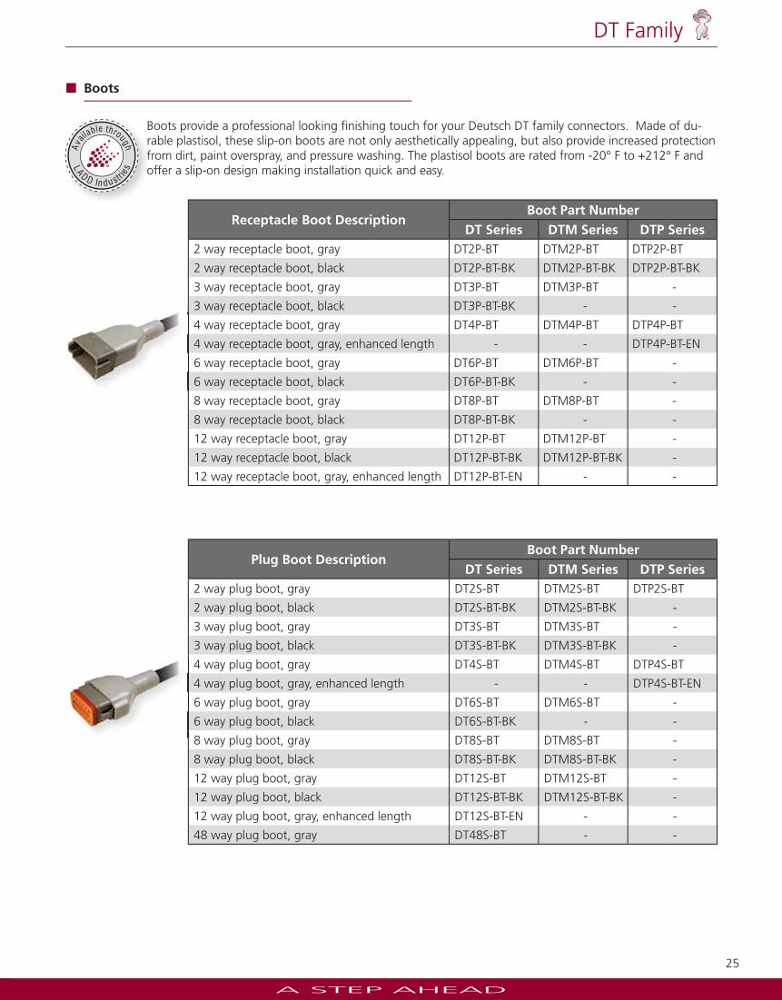
Receptacle Boot DescriptionBoot Part Number
DT Series DTM Series DTP Series2 way receptacle boot, gray DT2P-BT DTM2P-BT DTP2P-BT
2 way receptacle boot, black DT2P-BT-BK DTM2P-BT-BK DTP2P-BT-BK
3 way receptacle boot, gray DT3P-BT DTM3P-BT -
3 way receptacle boot, black DT3P-BT-BK - -
4 way receptacle boot, gray DT4P-BT DTM4P-BT DTP4P-BT
4 way receptacle boot, gray, enhanced length - - DTP4P-BT-EN
6 way receptacle boot, gray DT6P-BT DTM6P-BT -
6 way receptacle boot, black DT6P-BT-BK - -
8 way receptacle boot, gray DT8P-BT DTM8P-BT -
8 way receptacle boot, black DT8P-BT-BK - -
12 way receptacle boot, gray DT12P-BT DTM12P-BT -
12 way receptacle boot, black DT12P-BT-BK DTM12P-BT-BK -
12 way receptacle boot, gray, enhanced length DT12P-BT-EN - -
Plug Boot DescriptionBoot Part Number
DT Series DTM Series DTP Series2 way plug boot, gray DT2S-BT DTM2S-BT DTP2S-BT
2 way plug boot, black DT2S-BT-BK DTM2S-BT-BK -
3 way plug boot, gray DT3S-BT DTM3S-BT -
3 way plug boot, black DT3S-BT-BK DTM3S-BT-BK -
4 way plug boot, gray DT4S-BT DTM4S-BT DTP4S-BT
4 way plug boot, gray, enhanced length - - DTP4S-BT-EN
6 way plug boot, gray DT6S-BT DTM6S-BT -
6 way plug boot, black DT6S-BT-BK - -
8 way plug boot, gray DT8S-BT DTM8S-BT -
8 way plug boot, black DT8S-BT-BK DTM8S-BT-BK -
12 way plug boot, gray DT12S-BT DTM12S-BT -
12 way plug boot, black DT12S-BT-BK DTM12S-BT-BK -
12 way plug boot, gray, enhanced length DT12S-BT-EN - -
48 way plug boot, gray DT48S-BT - -
Boots
Boots provide a professional looking fi nishing touch for your Deutsch DT family connectors. Made of du-rable plastisol, these slip-on boots are not only aesthetically appealing, but also provide increased protection from dirt, paint overspray, and pressure washing. The plastisol boots are rated from -20° F to +212° F and offer a slip-on design making installation quick and easy.
A STEP AHEAD
26
DT Family
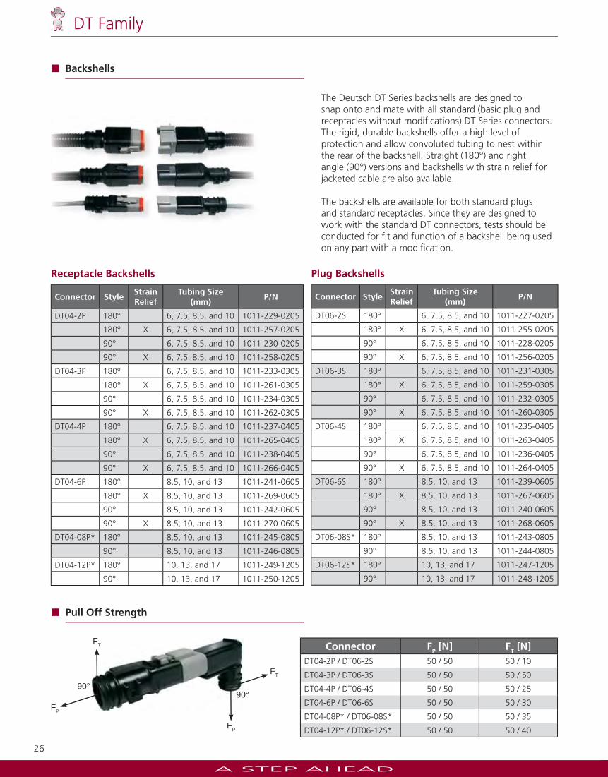
Receptacle Backshells
Connector Style StrainRelief
Tubing Size(mm)
P/N
DT04-2P 180° 6, 7.5, 8.5, and 10 1011-229-0205
180° X 6, 7.5, 8.5, and 10 1011-257-0205
90° 6, 7.5, 8.5, and 10 1011-230-0205
90° X 6, 7.5, 8.5, and 10 1011-258-0205
DT04-3P 180° 6, 7.5, 8.5, and 10 1011-233-0305
180° X 6, 7.5, 8.5, and 10 1011-261-0305
90° 6, 7.5, 8.5, and 10 1011-234-0305
90° X 6, 7.5, 8.5, and 10 1011-262-0305
DT04-4P 180° 6, 7.5, 8.5, and 10 1011-237-0405
180° X 6, 7.5, 8.5, and 10 1011-265-0405
90° 6, 7.5, 8.5, and 10 1011-238-0405
90° X 6, 7.5, 8.5, and 10 1011-266-0405
DT04-6P 180° 8.5, 10, and 13 1011-241-0605
180° X 8.5, 10, and 13 1011-269-0605
90° 8.5, 10, and 13 1011-242-0605
90° X 8.5, 10, and 13 1011-270-0605
DT04-08P* 180° 8.5, 10, and 13 1011-245-0805
90° 8.5, 10, and 13 1011-246-0805
DT04-12P* 180° 10, 13, and 17 1011-249-1205
90° 10, 13, and 17 1011-250-1205
Plug Backshells
Connector StyleStrainRelief
Tubing Size (mm)
P/N
DT06-2S 180° 6, 7.5, 8.5, and 10 1011-227-0205
180° X 6, 7.5, 8.5, and 10 1011-255-0205
90° 6, 7.5, 8.5, and 10 1011-228-0205
90° X 6, 7.5, 8.5, and 10 1011-256-0205
DT06-3S 180° 6, 7.5, 8.5, and 10 1011-231-0305
180° X 6, 7.5, 8.5, and 10 1011-259-0305
90° 6, 7.5, 8.5, and 10 1011-232-0305
90° X 6, 7.5, 8.5, and 10 1011-260-0305
DT06-4S 180° 6, 7.5, 8.5, and 10 1011-235-0405
180° X 6, 7.5, 8.5, and 10 1011-263-0405
90° 6, 7.5, 8.5, and 10 1011-236-0405
90° X 6, 7.5, 8.5, and 10 1011-264-0405
DT06-6S 180° 8.5, 10, and 13 1011-239-0605
180° X 8.5, 10, and 13 1011-267-0605
90° 8.5, 10, and 13 1011-240-0605
90° X 8.5, 10, and 13 1011-268-0605
DT06-08S* 180° 8.5, 10, and 13 1011-243-0805
90° 8.5, 10, and 13 1011-244-0805
DT06-12S* 180° 10, 13, and 17 1011-247-1205
90° 10, 13, and 17 1011-248-1205
Connector FP [N] FT [N]DT04-2P / DT06-2S 50 / 50 50 / 10
DT04-3P / DT06-3S 50 / 50 50 / 50
DT04-4P / DT06-4S 50 / 50 50 / 25
DT04-6P / DT06-6S 50 / 50 50 / 30
DT04-08P* / DT06-08S* 50 / 50 50 / 35
DT04-12P* / DT06-12S* 50 / 50 50 / 40
90°90°
FT
FP
FP
FT
Backshells
The Deutsch DT Series backshells are designed to snap onto and mate with all standard (basic plug and receptacles without modifi cations) DT Series connectors. The rigid, durable backshells offer a high level of protection and allow convoluted tubing to nest within the rear of the backshell. Straight (180°) and right angle (90°) versions and backshells with strain relief for jacketed cable are also available.
The backshells are available for both standard plugs and standard receptacles. Since they are designed to work with the standard DT connectors, tests should be conducted for fi t and function of a backshell being used on any part with a modifi cation.
Pull Off Strength
A STEP AHEAD
27
DT Family
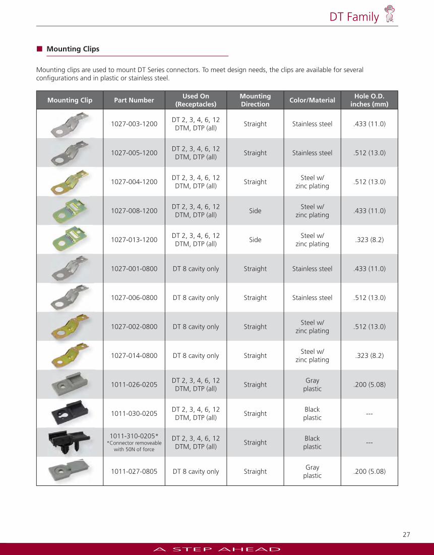
Mounting Clip Part NumberUsed On
(Receptacles)MountingDirection
Color/MaterialHole O.D.
inches (mm)
1027-003-1200DT 2, 3, 4, 6, 12DTM, DTP (all)
Straight Stainless steel .433 (11.0)
1027-005-1200DT 2, 3, 4, 6, 12DTM, DTP (all)
Straight Stainless steel .512 (13.0)
1027-004-1200DT 2, 3, 4, 6, 12DTM, DTP (all)
StraightSteel w/
zinc plating.512 (13.0)
1027-008-1200DT 2, 3, 4, 6, 12DTM, DTP (all)
SideSteel w/
zinc plating.433 (11.0)
1027-013-1200DT 2, 3, 4, 6, 12DTM, DTP (all)
SideSteel w/
zinc plating.323 (8.2)
1027-001-0800 DT 8 cavity only Straight Stainless steel .433 (11.0)
1027-006-0800 DT 8 cavity only Straight Stainless steel .512 (13.0)
1027-002-0800 DT 8 cavity only StraightSteel w/
zinc plating.512 (13.0)
1027-014-0800 DT 8 cavity only StraightSteel w/
zinc plating.323 (8.2)
1011-026-0205DT 2, 3, 4, 6, 12DTM, DTP (all)
StraightGray
plastic.200 (5.08)
1011-030-0205DT 2, 3, 4, 6, 12DTM, DTP (all)
StraightBlackplastic
---
1011-310-0205**Connector removeable
with 50N of force
DT 2, 3, 4, 6, 12DTM, DTP (all)
StraightBlackplastic
---
1011-027-0805 DT 8 cavity only StraightGray
plastic.200 (5.08)
Mounting Clips
Mounting clips are used to mount DT Series connectors. To meet design needs, the clips are available for several confi gurations and in plastic or stainless steel.
A STEP AHEAD
28
DT Family
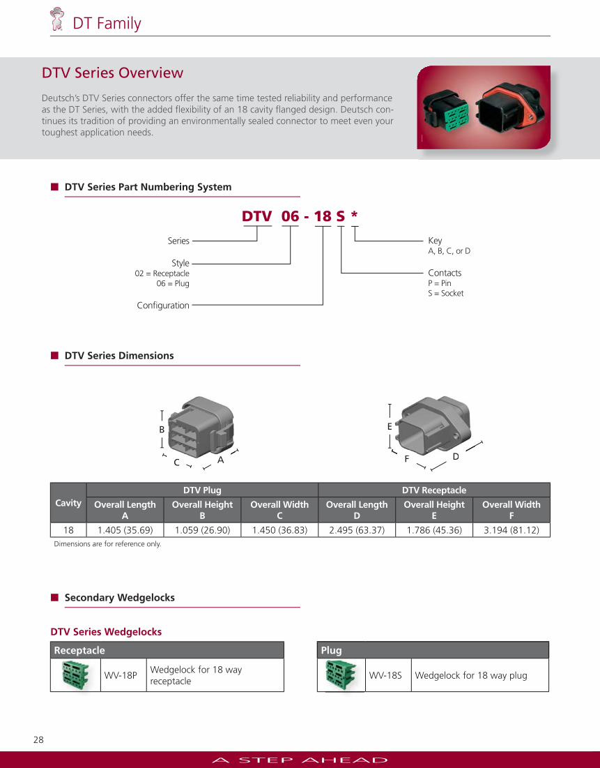
DTV Series Wedgelocks
Receptacle Plug
WV-18PWedgelock for 18 wayreceptacle
WV-18S Wedgelock for 18 way plug
DTV Series Overview
Deutsch’s DTV Series connectors offer the same time tested reliability and performance as the DT Series, with the added fl exibility of an 18 cavity fl anged design. Deutsch con-tinues its tradition of providing an environmentally sealed connector to meet even your toughest application needs.
DTV 06 - 18 S *
Series
Style02 = Receptacle
06 = Plug
Confi guration
KeyA, B, C, or D
ContactsP = Pin S = Socket
CavityDTV Plug DTV Receptacle
Overall LengthA
Overall HeightB
Overall WidthC
Overall LengthD
Overall HeightE
Overall WidthF
18 1.405 (35.69) 1.059 (26.90) 1.450 (36.83) 2.495 (63.37) 1.786 (45.36) 3.194 (81.12)Dimensions are for reference only.
DTV Series Part Numbering System
DTV Series Dimensions
Secondary Wedgelocks
E
F DF D
B
C AC A
A STEP AHEAD
29
DT Family
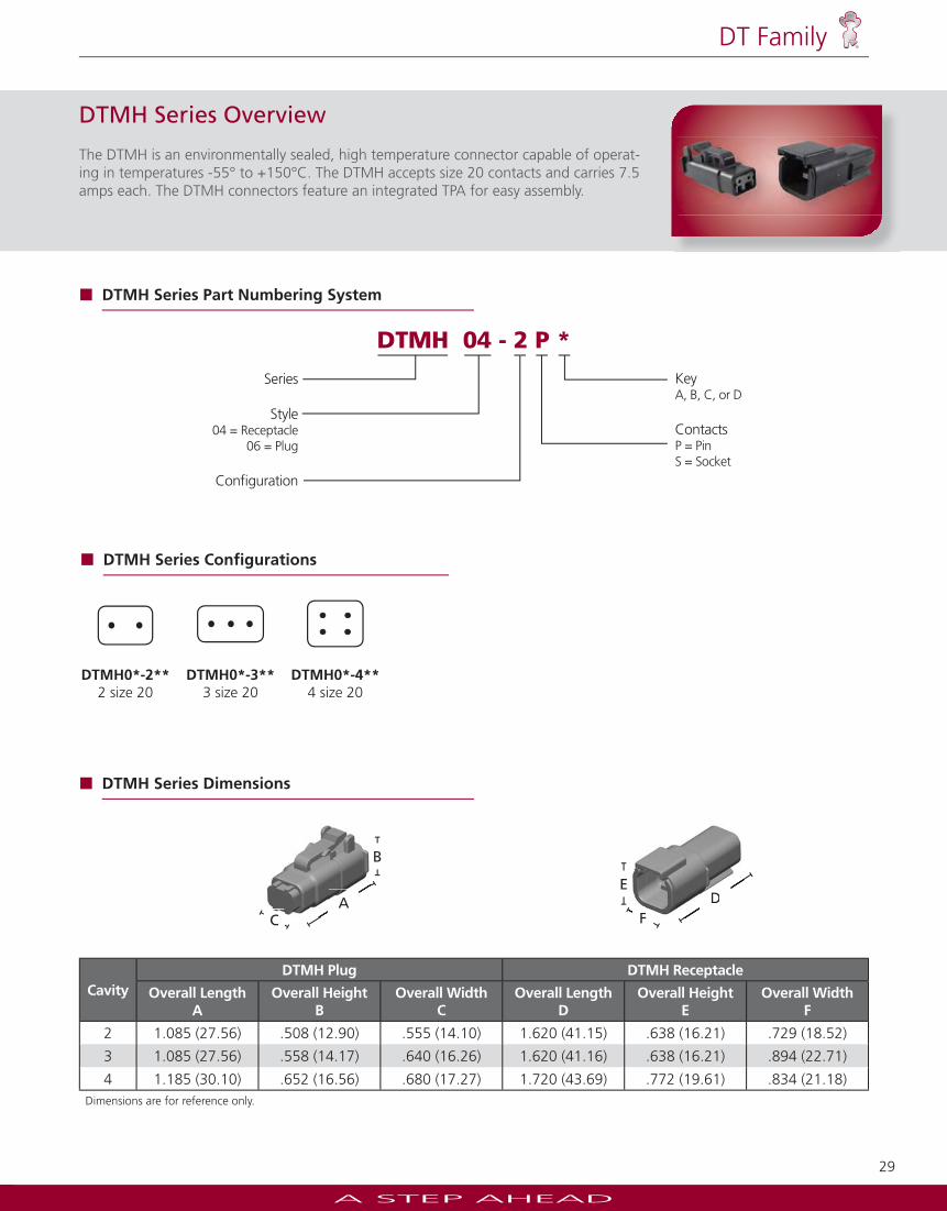
DTMH Series Overview
The DTMH is an environmentally sealed, high temperature connector capable of operat-ing in temperatures -55° to +150°C. The DTMH accepts size 20 contacts and carries 7.5 amps each. The DTMH connectors feature an integrated TPA for easy assembly.
CavityDTMH Plug DTMH Receptacle
Overall LengthA
Overall HeightB
Overall WidthC
Overall LengthD
Overall HeightE
Overall WidthF
2 1.085 (27.56) .508 (12.90) .555 (14.10) 1.620 (41.15) .638 (16.21) .729 (18.52)
3 1.085 (27.56) .558 (14.17) .640 (16.26) 1.620 (41.16) .638 (16.21) .894 (22.71)
4 1.185 (30.10) .652 (16.56) .680 (17.27) 1.720 (43.69) .772 (19.61) .834 (21.18)Dimensions are for reference only.
DTMH Series Dimensions
AC
B
AC F
ED
FD
DTMH0*-2**2 size 20
DTMH0*-3**3 size 20
DTMH0*-4**4 size 20
DTMH Series Confi gurations
DTMH 04 - 2 P *
Series
Style04 = Receptacle
06 = Plug
Confi guration
KeyA, B, C, or D
ContactsP = Pin S = Socket
DTMH Series Part Numbering System
A STEP AHEAD
30
DT Family
CavityDTMN Plug DTMN Receptacle
Overall LengthA
Overall HeightB
Overall WidthC
Overall LengthD
Overall HeightE
Overall WidthF
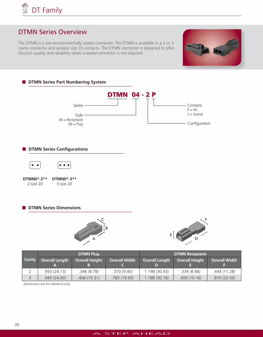
2 .950 (24.13) .346 (8.78) .370 (9.40) 1.198 (30.43) .334 (8.48) .444 (11.28)
3 .945 (24.00) .406 (10.31) .785 (19.93) 1.188 (30.18) .400 (10.16) .810 (20.56)Dimensions are for reference only.
DTMN Series Dimensions
ED
F
B
A
C
A
C
DTMN Series Overview
The DTMN is a non-environmentally sealed connector. The DTMN is available in a 2 or 3 cavity connector and accepts size 20 contacts. The DTMN connector is designed to offer Deutsch quality and reliability when a sealed connector is not required.
DTMN0*-2**2 size 20
DTMN0*-3**3 size 20
DTMN Series Confi gurations
DTMN 04 - 2 P
Series
Style04 = Receptacle
06 = Plug
ContactsP = Pin S = Socket
Confi guration
DTMN Series Part Numbering System
A STEP AHEAD
31
DT Family
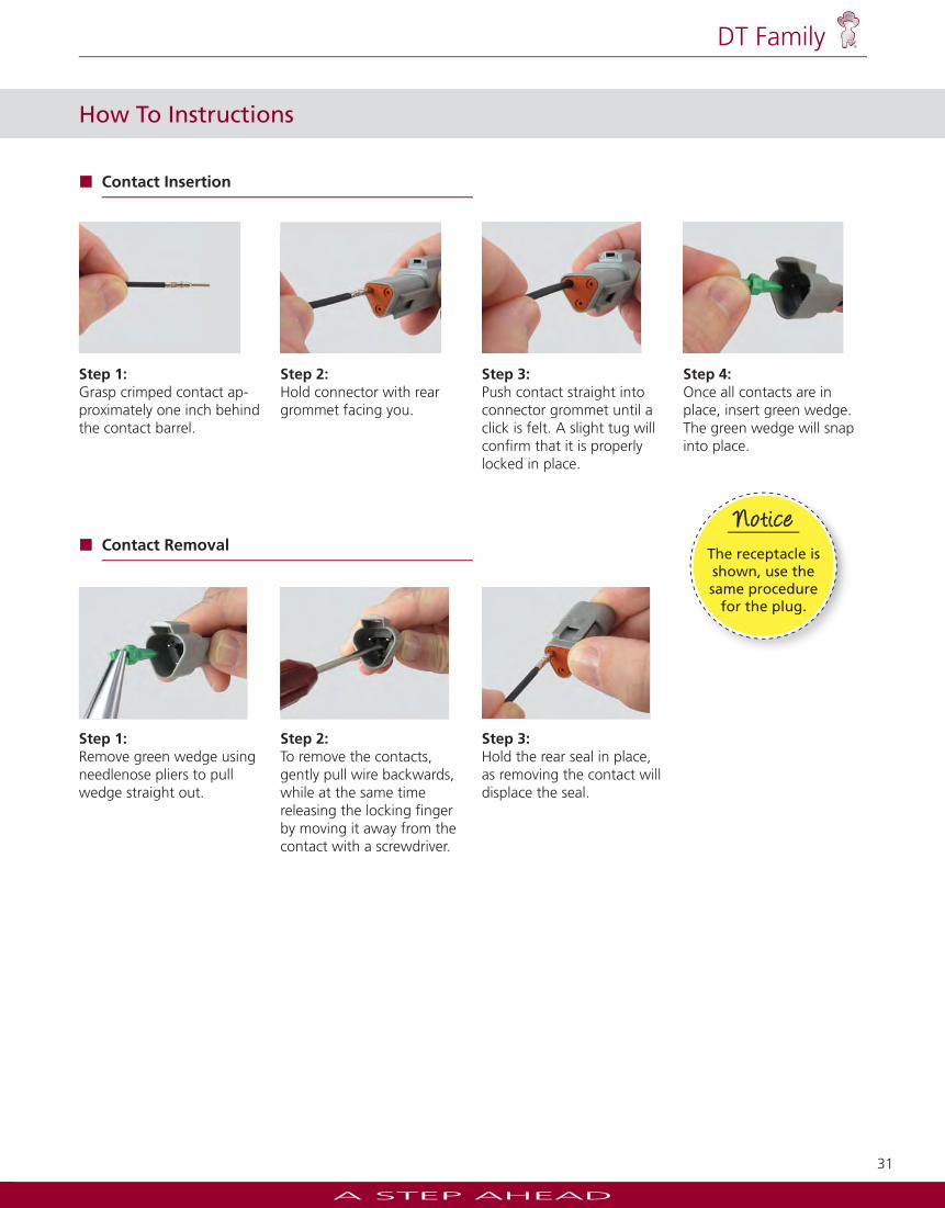
Step 1:Grasp crimped contact ap-proximately one inch behind the contact barrel.
Step 2:Hold connector with rear grommet facing you.
Step 3:Push contact straight into connector grommet until a click is felt. A slight tug will confi rm that it is properly locked in place.
Step 4:Once all contacts are in place, insert green wedge. The green wedge will snap into place.
How To Instructions
Contact Insertion
Step 1:Remove green wedge using needlenose pliers to pull wedge straight out.
Step 2:To remove the contacts, gently pull wire backwards, while at the same time releasing the locking fi nger by moving it away from the contact with a screwdriver.
Step 3:Hold the rear seal in place, as removing the contact will displace the seal.
Contact Removal
Note
Jiffy Splicesaccept one pin and one
socket.
NoteeeJiffy Splicesaccept one pin and one
socket.
NoteNNNNoteoteoteNoNoooooteteteteNNNNNNNN ttNNNote
The receptacle is shown, use the same procedure
for the plug.
NoticeNotice