Electronics Systems Communications Monitor&Control Satellite Telco Sys
description

D&T: Electronics and Control Systems
Name: Alexander LloydCandidate Number: 9177Centre Number: 16527
Unit A511: Introduction to designing and making

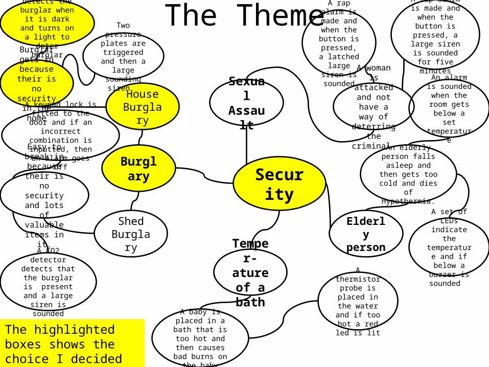
The ThemeI have chosen the theme security because their has been a number of cases of security problems in the newspaper recently and they have all been caused because of their is no criminal deterrence when no one is in the home. The product I intend to build improves home security and make the user feel more secure.
SecurityBurglar
y
Shed Burglary
House Burglary
Sexual Assault
Elderly person
Temper-ature of a bath
Burglar gets in because their is no security in the home
Easy to break in because their is no security and lots of valuable
items in it.
The ThemeA PIR sensor detects the
burglar when it is dark and turns on
a light to deter burglar
Two pressure plates are
triggered and then a large
sounding siren
A CO2 detector detects that the
burglar is present and a large siren is
sounded
A keypad lock is fitted to the door and if an
incorrect combination is inputted, then an
alarm goes off
A woman is attacked and
not have a way of
deterring the criminal
A rap alarm is made and when the button is
pressed, a latched large
siren is sounded
A rap alarm is made and when
the button is pressed, a large siren is sounded for five minutes
An elderly person falls asleep and
then gets too cold and dies of
Hypothermia.
An alarm is sounded when the room gets
below a set temperature
A set of LEDs indicate the temperature
and if below a buzzer is
sounded
A baby is placed in a bath that is too
hot and then causes bad burns
on the baby
A thermistor probe is placed
in the water and if too hot a
red led is lit The highlighted boxes shows the choice I decided to made for my product

User NeedsDomestic Burglaries
are on the rise. so a new product is needed to help protect the homes. Below is a picture of a burglary. Also their is a newspaper cutting that shows that their are in the local area. Some statistics show that burglaries are on the rise. This may be due to the current economic recession.
This is an article of a burglary in the local area
2009 2010 20110
2
4
6
8
Burglary in Essex per 1,000 people
Burglary in Essex Burglary in Essex
2009 8.17
2010 7.56
2011 8.23
A burglar in the act of Burglary
Statistics showing Burglaries on the rise
This is me conducting a questionnaire about this projectThe newspaper
clipping shows that their are burglaries in the local area. In the clipping, their was luckily nothing stolen. It happened during the nightConclusionThe conclusion is that their is a need for the intended product. It must be able to deter the burglar from the house and must do it during the night
where most burglariesoccur.

Questions for the Questionnaire 1. Are you out of the home a lot?
This is so I know that their are people who need the product I propose.2.Would you want their to be a switch to turn off the system?This will allow me to decide to put a switch in because the users needs it.3. Would you want the light to go off after some time? This will allow me to decide whether to have a latch or not.4. Would you want the time the light is on is be adjustable?This will determine what type of variable resistor I will use.5. Would you want it to run on mains power? This so I can decide a power source.6. Would you want more than one light to go on? This is so I know whether another light is needed in the circuit.7. Do you already have security devices in your home?This will determine whether their is a potential for my product .8. Do you want it to be house in a box?This will determine whether I need to get a box for my product.9. Do you want it to have a power indicator?This is so I know whether a LED indicator is required.10. Would you want a delay after the burglar has
been detected ?This will allow me to on parts of the circuit that is required.

The QuestionnaireThe results of my questionnaire:
Questionnaire Questions Yes No
1. Are you out of the home a lot? 7 32.Would you want their to be a switch to turn off the system? 6 43. Would you want the light to go off after some time? 9 14. Would you want the time the light is on is be adjustable? 6 45. Would you want it to run on mains power? 2 86. Would you want more than one light to go on? 1 9 7. Do you already have security devices in your home? 3 78. Do you want it to be house in a box? 5 59. Do you want it to have a power indicator? 8 2 10. Would you want a delay after the burglar has been detected ? 7 3
The Trend of the QuestionnaireThese results show that people are out of the house a lot. Also the target audience don't have a security device . With the proposed product, they want a light that goes off after an adjustable amount of time and that it has batteries with a switch so that it can be turned off. It must also only run one light with a delay and have a power indicator.

Product ComparisonProduct Cost Typical
user When / Where used?
function Technology used
Manufacturing process used
400 watt halogen flood light
£6.00Wickes
Used to light a driveway so the person arriving in the dark can see up their driveway.
Terns on when their is motion in front of the sensor has a variable timer to turn the light off.
Die-cast Aluminium and PCB with components soldered.
AA7-LCD GSM Wireless Home Security Burglar Alarm
£324.99Amazon
It is used in an office where there is a risk of burglary at night when no one is in the office.
Many Inputs into a large sounding alarm and also sends you a text message saying that the alarm has gone off.
It has multiple inputs that detect whether the case of the alarm is being remove. It can have a total of 40 inputs and different outputs including alarm and calling a preset number.
Aluminium case with Printed circuit board.
Friedland Response ML1 Shed Alarm
£16.48Amazon
A person with a Shed at the end of the garden and the owner is concerned that in the night tools will be stolen.
Type in a pre-recorded four digit number that then gives you 20 seconds to open the door and has an alarm.
Injection moulded plastic with PCB.
Light Sensor
Motion Sensor
Light
Reed Switch
Key Pad
Alarm

Design Brief• The device I propose will enhance security in your home. It
will deter burglars by turning on a light inside of the home so it seems that someone is inside. The product will be inexpensive by using cheap parts. I will use circuit wizard 2 to help design the circuit.
Trend of product ComparisonThe trend of the three products is that the more expensive the product, the more reliability the product has. Also the cheaper the product, the cheaper the case. Another point is that the more it costs, the more features.ExplanationThis is because electronic components cost money and the more features it has the more components needed for the intended purpose.EvidenceThe evidence is that the Halogen light bulb is a simple circuit and has few features so it is cheap. The Shed Alarm has a cheap Case but has a larger circuit so more components are used increasing the price. The large alarm system has a huge circuit with so many add-ons, this is why it costs so much.

Product Analysis400 watt halogen flood light
£6.00Outdoor LED Floodlight 9w With
PIR Motion Detector£37.95
Function Shines light when dark and motion detected. Amount of time light is shining is adjustable and how dark the light comes on is also adjustable.
Shines 130 LEDs when motion detected and dark outside. It then turns off after a preset time which is adjustable.
User need fulfilled
The user needs are almost fulfilled but the product does not turn on a light inside.
This product almost fills the user needs .
Materials used in construction
Material used are: Plastics, PCB. Materials used are Plastics and PCB.
Durability of product
This Product ins very durable because of it basic shape and fail safe circuit.
This product is very uncomplicated shape and a simple circuit making it very durable.
Sustainability (6Rs)
The halogen light uses 400 watts of power. Lots of useful parts in side of device. It has no built in opalescence except the light breaking.
The LEDs can be used because of their low voltage and lots of useful parts in the floodlight. It has no built in opalescence .
Life cycle
Energy use 400 Watt Output. Uses 9W of power to shine 200watts from the LEDs.
TrendThese product show that a higher priced light means that it uses less power but do not get
a higher power rating the larger the price.

SpecificationDescription Explanation Evidence from Research
Functional Specification1.My proposed product will detect when a person is walking up the driveway and will turn on a light in the house.2.The System will need to sense whether its dark and if the burglar is detected.3.An NAND Gate will be used to combine the inputs so it goes on with motion and when it is dark.4.The output will be a lamp.5.It will be powered by 9volts.6.This proposed product will have a SPDT to act as an on/off switch.7.It will have a power indicator.
1.This will put off a burglar because he will think someone is in the house.2.The will allow the server to work as the design brief says. If it wasn't like this, then it will turn on in the day when the proposed product will not be very effective3.The NAND is needed because a negative spike is required to trigger the 555 Timer and the NAND will provide this.4.This is so it meets the design specification5.This is because lot of components run on this voltage.6.The user is able to turn the system off and when required.7.This is so the user when it is on.
1.The Newspaper Article in User Needs shows a burglary happening at night. If the proposed product was in place this may of not happened.2.The Newspaper cutting shows that a system with a dark sensor and motion from the burglar will be required for this to work to a full potential.3.The Questionnaire shows that the light need to be on for a short time. A 555 timer is the best option because it can have a variable controlled time and this must be trigged with a negative pulse,. This is also asked in question 4, it ask whether a variable amount of time is required, the results show 6 people said yes,4.The Design Brief says it will turn on a light in the home and a lamp will make the product more affordable and simplest option will mean it is more reliable because of it simplicity.5.Question 5 on my questionnaire concluded that 8 of the 10 wanted it to be run on batteries6.Question 2 asks whether a switch is required, the results show that people want a switch.
Physical Specification
1.The Circuit board will be made using ultra violet etching.
1.This is to reduce the possibility of a short circuit.
Manufacturing Specification
1.It will be designed using Circuit wizard 2.2. I will ensure that the circuit will be well built and work.
1. This is because it is easy to use and has all the components I need.
2. This will be done by checking the quality of the product as I build the circuit, this is to ensure their are no errors in the wiring and placing of the components so the product will work for its intended purpose.
1. N/A2. N/A

System DiagramDelay before input
Input Combine Inputs
Delay after Inputs
Process Delay before Output
Output
30 Seconds After a switch is turned on
PIR Motion Detector
AND 30 second delay
Transistor 0 Seconds Relay
0 seconds Heat Sensor
OR 1 minute delay
MOSFET 30 Seconds
Power Indicator
15 seconds
Dark Sensor
NAND 0 seconds Darlington Pair
1 Minute Siren
2 minutes Infrared Laser beam break
NOR 10 Seconds
Thyristor 2 minutes Lamp
EX-OR 2 minutes 555 Monostable
The Highlighted boxes indicate the building blocks I plan to use

Ideas for CircuitWhen the switch is closed and is dark and motion is detected (the 3-pin terminal block) the NAND gate triggers the negative trigger pin on the 555 and then stays in for a certain amount of time. It closes the relay pins.
When it is dark and motion is detected (the 3-pin terminal block) the AND and NOT gate triggers the negative trigger pin on the 555. The two inputs turn on the AND gate and the NOT gate inverts it . This triggers the negative trigger pin and then stays in for a certain amount of time. It closes the relay pins. This also has a power indicator.
Inputs Outputs
Dark sensor
Relay
Motion sensor
Inputs Outputs
Dark sensor
Relay
Motion sensor
LED Indicator
Advantages Disadvantages•Very Simple •AND gate does not work with
the 555 timer
Advantages Disadvantages•The 555 will now •Too many Integrated circuits

Ideas for CircuitWhen it is dark and motion detected the AND gate triggers the OP amp and then the short negative pulse to trigger the 555 timer chip which then has a delay to the relay. It also has a power indicator.
Inputs OutputsDark sensor RelayMotion sensor
LED Indicator
Inputs OutputsDark sensor RelayMotion sensor
LED Indicator
Advantages Disadvantages•Works very well •Very complicated
When the dark sensor and motion is detected it triggers the AND gate which is amplified by the transistor to create a short negative spike which triggers a 555 timer. This is then connected to the relay. It also has a power indicator.
Advantages Disadvantages•Works very well •Very complicated and has too
many components.

Development of the chosen circuitThis is the first circuit
I added an AND gate because the circuit description is that it needs to be dark and motion detected.
This detects motion and triggers a lamp.

Development of the chosen circuitI added a power
indicator so the user knows it is on. I also added a
monostable because it needed to be on for a certain amount of time.
I finally added a delay because it needed a delay before the output was on.

The Testing of the circuit

The PCBThe four PCBs below are the developmentwhile the PCB to the right is one that does not work because it tracks overlapped.
1.
3.
2.
4.
Their was a ‘rats nest’ here so I expanded the components.
Here I have expanded the circuit and got rid of the rat nest. But their was still a lot of blue wires so I moved the components further.
Here I continued to move the components and was able to remove all but two blue wires.
Here is my final circuit.
The NAND inputs have all been grounded so that a static charge built up will not affect the input used.

The Final PCB and Bill of Materials Name Cost Quantity Total
1000μF Electrolytic Capacitor £ 0.19 1 £
0.19
200μF Electrolytic Capacitor £ 0.19 1 £
0.19
100KΩ Potentiometer £ 0.79 2 £
1.58
1MΩ Potentiometer £ 0.79 1 £
0.79
330Ω Fixed Resistor (1/4 Watt) £ 0.01 1 £
0.01
4011 Quad 2-Inout NAND Gate £ 0.14 1 £
0.14
NE555 Bipolar Timer £ 0.15 1 £
0.15
Green LED (0.2in , 5mm) £ 0.05 1 £
0.05
Light Dependant Resistor (OPR12) £ 0.93 1 £
0.93
ZVN3306A N Channel MOSFET £ 0.22 1 £
0.22
PIR Sensor £ 7.15 1 £
7.15
Signal Lamp £ 1.99 1 £
1.99
PP3 Battery Snap £ 0.25 1 £
0.25
3.2 (W) x 2.3 (H) Printed Circuit Board
£ 2.88 1 £
2.88
Total: £ 16.52

The Testing of the PCB

Planning for ManufactureDescription of process
Equipment required
Safety issues Tips for success
Design PCB and Mask. Circuit wizard 2 program None Remove as many blue wires. No rats nests (green wires) Test circuit at each stage of development
Cut board to size Band Saw Don't touch saw, its Sharp. Blade will also be hot after cutting. When blade is running, keep hands away
Measure Board accurately. Cut carefully. Do this process quickly because the copper clad starts to oxidise.
Expose mask, and PhotoPCB to UV light for 4 minutes.
UV lightPhotoPCBMask of my circuit
Make sure the UV light is covered up because UV light will damage eyes
Expose board for around 10 minutes
Develop exposed PCB Development Fluid Wear Goggles and safety equipment. Development fluid is an Acid. It is corrosive.
Wear correct safety clothing
Etch PCB Bubble etch tankEtchant
Etchant Corrosive. Avoid getting on skin. If you do, wash off quickly.
Wear goggles and gloves. Leave in etchant for 1 – 2 minutes.
Drill holes DrillDrill Press
Don’t put hands on near drill bit. Wear goggles because fragments of material may go into your eyes.
Make sure drill is centred over pad.
Solder chip sockets SolderSoldering Iron14 pin chip socket8 pin chip socket
Soldering iron is hot. Don’t melt the plastic socket. Solder is from lead. Handle with care.
Make sure all pins of the socket are correctly placed before and during soldering.
Solder Resistors SolderSoldering IronFixed ResistorsVariable Resistors
Soldering iron is hot. Avoid overheating all resistors.
Use the correct value resistors. It does not matter what way the fixed resistor is fitted and soldered but the variable resistors have three pins that have to go in the right way

Description of process
Equipment required
Safety issues Tips for success
Solder Capacitors SolderSoldering IronCapacitor
Soldering iron is hot. The electrolytic capacitors need to placed in the hole the right way. Electrolytic capacitors have a negative line along the side so you know what way to place the component.
Solder LED SolderSoldering IronLED
Soldering iron is hot. Solder the LED the right way,. The Cathode is the negative side and is marked by a longer wire and also the led has a sector of the led removed which also means the negative side
Solder MOSFET SolderSoldering IronMOSFET
Soldering iron is hot. Solder the MOSFET the same way as the picture printed off of the circuit. IF the MOSFET is the wrong way, then the MOSFET and the circuit may be damaged.
Solder off board components
SolderSoldering IronWireSPST SwitchBulbLight Dependant ResistorPIR passive infrared sensorPP3 Battery clip
Soldering iron is hot. The Battery, and PIR must be put in the way that is on the picture. The others can be placed any way round but must be in the allocated holes on the PCB.
Shrink wrap connections between off board components and wires
SolderSoldering IronHeat GunHeat-sink
Soldering iron is hot. Shrink Wrap is a very quick process heat carefully and accurately.
Add chips to chip sockets 555 timer chip4011 Quad Dual input NAND
Soldering iron is hot. Add the chips carefully and make sure the terminals are not overlapping.
Test the circuit Finished CircuitPower Supply
Power Supply could cause an electric shock use with care.
Use 9 Volts and test circuit.
Planning for Manufacture Continued
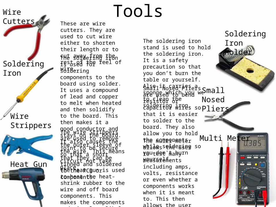
ToolsThese are wire cutters. They are used to cut wire either to shorten their length or to cut away from the rest of the reel of wire.The soldering iron is used for soldering components to the board using solder. It uses a compound of lead and copper to melt when heated and then solidify to the board. This then makes it a good conductor and stays on the board. It also causes the joint to be secure so that a short circuit not take place.
The soldering iron stand is used to hold the soldering iron. It is a safety precaution so that you don’t burn the table or yourself. Also it carries a sponge which you wet to clean the soldering iron.
The wire Strippers are used to remove the outer sleeve of the wire. This means that they can be tinned and soldered to the PCB or components.
Wire Cutters
Soldering Iron
Soldering Iron Holder
Wire Strippers
Heat GunThe heat gun is used to heat the heat-shrink rubber to the wire and off board components. This makes the components and wire less likely to break.
Small Nosed Pliers are used to bend resistor or capacitor wires so that it is easier to solder to the board. They also allow you to hold the components while soldering so you don't burn yourself.
Small Nosed Pliers
Multi MeterThe multi-meter allows the user to test many measurements including amps, volts, resistance or even whether a components works when it is meant to. This then allows the user to pin point if a components or part of the board is working.

Manufacturing the circuit, the PCBFirst the PCB has to be
printed on glossy flexible transparent plastic. A laser printer will need to be used because laser ink does not dissolve in the etching fluid. The Ink protect the copper to make the tracks.
1.
2. Stick the PCB to a pre-cut to size the Copper clad. The copper must be the same size as the print out border of the PCB. It may have a protective plastic over the photo-resistant, if so then take it off and go on to the next step
3. Place the Copper clad and Printed out PCB in the ultraviolet light where this will cause a chemical change to the unprotected copper and it becomes easier to etch later on.
4. Place the treated board into the etching tank, this is a very difficult part because if over developed, then the board may be unusable.Drill the holes for the PCB. This is done by using a 1mm drill bit in a small pillar drill. Align the drill with the where you want to drill the hole. Then with the board held tightly push the pillar drill into where you want the hole. Note that some components such as variable resistors will need bigger holes. The PCB is now ready for soldering components on.
5.

Manufacturing the Circuit, the soldering
This is the PCB without any components on the board. I started the soldering by soldering the variable resistors on to the board.
Here I soldered the variable resistors. This soldering went well and the joints looked good.This is me soldering the potentiometers to the board by placing a little solder on the soldering iron
and then placing on the resistor with the solder to create a even joint.
To start off, I soldered wires to the off board components to wires so that they are off the board. To do this I got a piece of heat shrink and covered a tinned wire and the component so that they are connected. Then I tinned the other side of the wire so that it had a little solder on. I did this for all the switch, LED, bulb wires, LDR and PIR sensor.
Next, I used the heat gun to add heat shrink to the wire so that the joint between the wire and the component was more secure and it meant that the wires could not short circuit. It also meant that the wires had a small degree of water proofing so that it could be used outside.

Manufacturing the Circuit, the solderingNext was the
resistor. I first made sure it was the right one. It should be 330Ω resistor. This should be orange orange brown. In the picture you can see that this is the right resistance.
I was going to put in the large 1000μF capacitor but I encountered the problem that the capacitor went over the wire so I soldered the wire in. The picture below shows the capacitor on top of the wire. The wire has insulation so that the metallic base of the capacitor does not cause a short circuit
Then I realised that I had soldered the capacitor pads together. This would cause the charge of the capacitor not to happen and a low resistance route to the negative terminal and the MOSFET would not trigger. This was resolved by using a solder sucker. The picture below is the capacitor fixed. Then I soldered the 200μF capacitor in with no problems. I made sure to check if they were the right way because these capacitors are electrolytic which means that they are polarised so they need to be placed in the right way.

Manufacturing the Circuit, the soldering
The chip socket was soldered next. I soldered the notch in the same way as the chip notch. This is because the chip will not fit in if the sockets not in the right way.
Now I soldered the off board components to the board. I started with the PIR, then the Light dependant resistor, bulb wires, LED, switch and lastly battery. I looked at a picture of the circuit printed off circuit wizard so that I knew the right way to place polarised components such as the PIR and battery. Then the NAND gate and 555 timer chips were placed in the appropriate chip socket. This had to be placed carefully because the chip pins could bend and the chip may be unusable. Also your static may damage your chip.
When testing the circuit, I noticed that the bulb was alit a little. I then realised that the battery was wired the wrong way round. This occurred because the red and black looked similar on a black and white printout. This was corrected and the circuit tested again. I then went on to the test plan.
The MOSFET was then soldered in with no problems. It has too be placed in the right way because it is polarised. If placed in the wrong way, then the MOSFET would get damaged and the circuit will not work.

Problems when manufacturing the circuit• When putting in the potentiometers, the holes
were too small, so I used a small drill to increase the size of the holes. Then they fitted in.
• The 1000μF capacitor was very big and overlapped a wire. So I soldered the wire in first with insulation on so it would not short circuit. Then the capacitor went on top.
• Then while checking the pads after soldering, I noticed that I had used too much solder and they had caused a large joint. This would mean that the circuit would not work so I used a solder sucker and removed the solder and then soldered the joint again.
• The PIR was faulty so that the circuit would operated differently to the expected result. This was changed and a tested working PIR sensor was soldered in.
• The battery snap was not soldered in the right way because the red positive and black negative looked similar on the black and white circuit diagram. This was corrected and the problem was resolved.

The finished circuitThis is the component side of the circuit.
This is the solder side of the circuit
This is the complete circuit with off board components

Testing PlanTesting Plan
Test Expected Result Actual Result Result (or X)
Turn on the circuit using the switch.
A green LED should turn on. The LED did not turn on but the bulb was on a little. I quickly realised that the battery snap was in the wrong way. The bulb went on because it is no polarised. I then re-soldered the battery snap the right way.
X
Take outside during the day. Trigger the PIR.
This should not have any response because the NAND does not trigger the 555 timer. Using a voltmeter, pin 3 of the 555 should be 0 Volts and pin 10 should be around 9 volts.
Their is no response. This meant the product was working the way it should of.
Place in a dark place. Then trigger the PIR again.
A little wait but will go on for 2 minutes. This is because the inputs trigger the NAND and the rest of the circuit. Then if the middle 100K Potentiometer is at 0Ω, then the time constant will be 0 Seconds but at full resistance 100K it should stay on for
It went on but not for 2 minutes. This meant I had to adjust the middle variable resistor . This would mean the timing would work to the specification.
X
Wait until the light goes on and then off. Trigger PIR again.
This should turn on the bulb same as the last test in staying on for 2 minutes.
Because the variable resistor was adjusted in the last step in the test plan, then circuit worked to the way the specification states.
Turn off the switch. Now trigger the PIR once again
The LED should not be on and the bulb should not be on.
The switch is wired in correctly so this worked. The LED and bulb did not go on.

EvaluationDescription of process
What went well(What did you do to avoid
errors)
Problems encountered or changes made
Action taken to deal with problem
Design PCB and Mask. Using Circuit Wizard to design the PCB to remove rats nests and shrink the board in order to reduce amount of copper clad used.
When attempting to shrink the board by moving the components and tracks, the software would join tracks together which would mean the circuit would not work to the specification.
Going back to an old copy of the PCB and then taking great care in moving tracks would mean that the PCB would work to how i wanted it to. Also testing the circuit regularly will show I problem if it worked differently to how i wanted it to then i would know that their is a problem with the PCB and it could pin point an error.
Cut board to size
Using the band saw by sticking the image to the copper clad and following the lines of the PCB from the paper. This meant the sides were very accurate.
No problems were uncounted during this step
No action required.
Expose mask, and PhotoPCB to UV light for 4 minutes.
It was exposed for the right amount of time so that the tracks were not exposed to little or too much.
No problems were uncounted during this step
No action required.
Develop exposed PCB The development of the circuit went really well because it was exposed for right amount of time.
No problems encountered No Action Required
Etch PCB It was placed in the etching tank for the right amount of time so that it looked like a very good PCB.
No Problems were uncounted
No problems were encountered.
Drill holes I used a picture of the finished circuit printed from circuit wizard.
The variable resistor holes needed to be a drill size bigger.
I used a drill bit a millimetre bigger than the last. They then fitted in with problem.
Solder chip sockets
The solder joints were soldered well.
I changed the order of the plan so that the chip sockets was soldered before the MOSFET and after the capacitors.
This was changed because I felt that they would get in the way of other components
Solder Resistors
The variable resistors now fitted in the holes. The fixed resistor was soldered very well.
The holes were slightly misaligned but they still were in the solder pad.
No action was required.
Evaluation continuedDescription of process
What went well(What did you do to avoid
errors)
Problems encountered or changes made
Action taken to deal with problem
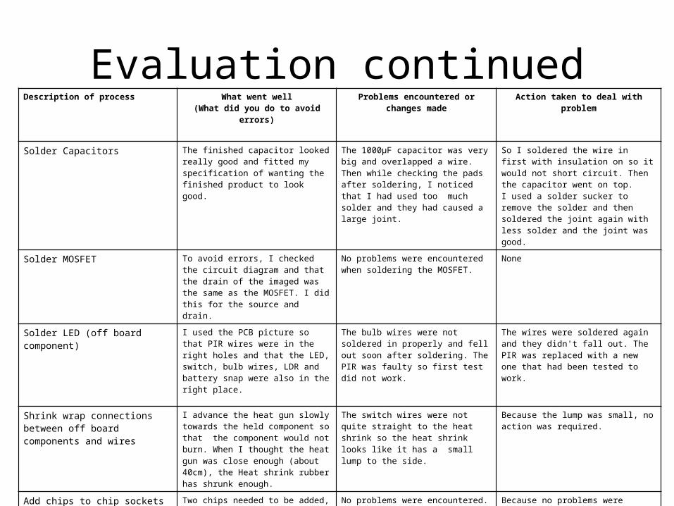
Solder Capacitors
The finished capacitor looked really good and fitted my specification of wanting the finished product to look good.
The 1000μF capacitor was very big and overlapped a wire.Then while checking the pads after soldering, I noticed that I had used too much solder and they had caused a large joint.
So I soldered the wire in first with insulation on so it would not short circuit. Then the capacitor went on top.I used a solder sucker to remove the solder and then soldered the joint again with less solder and the joint was good.
Solder MOSFET
To avoid errors, I checked the circuit diagram and that the drain of the imaged was the same as the MOSFET. I did this for the source and drain.
No problems were encountered when soldering the MOSFET.
None
Solder LED (off board component)
I used the PCB picture so that PIR wires were in the right holes and that the LED, switch, bulb wires, LDR and battery snap were also in the right place.
The bulb wires were not soldered in properly and fell out soon after soldering. The PIR was faulty so first test did not work.
The wires were soldered again and they didn't fall out. The PIR was replaced with a new one that had been tested to work.
Shrink wrap connections between off board components and wires
I advance the heat gun slowly towards the held component so that the component would not burn. When I thought the heat gun was close enough (about 40cm), the Heat shrink rubber has shrunk enough.
The switch wires were not quite straight to the heat shrink so the heat shrink looks like it has a small lump to the side.
Because the lump was small, no action was required.
Add chips to chip sockets Two chips needed to be added, the NAND gate and 555 timer. They were placed in by earthing yourselves so that you have no static charge.
No problems were encountered.
Because no problems were encountered. No Action needed to be taken.
Test the circuit
I followed the test plan when the LED indicator went on with no problems.
This was because when it was first turned on, I realised the battery was the wrong way. This cause the chips to get hot but i turned the circuit off before any damage was caused.
I soldered the battery clip in the right way and this meant the circuit worked.

Manufacturing and Functional EvaluationManufacturing Functional
• I think I could have made the Printed Circuit Board smaller because their are areas in the Board where their is not a track or a component. This would mean that less materials are used during the making of the product such as copper clad and ferric chloride.
• If a used this NAND gate delay instead, it would of taken advantage of the rest of the NAND gates that were not used and not to have to use the MOSFET. Also it would of seemed as if the light was switched on instead of what the final circuit does where it amplifies and goes on gradually. The specification says that it needed to be turned on as if it was a switch.
• Another option is to solder the LED to the printed circuit instead of being an off board component. This would mean less wire is used and would reduce the price of the final product.
• Adding a test button would mean the user can test if the bulb is working. This would be done by adding a push button between the drain of the MOSFET and 0 Volts. It would not cost much to add this to the PCB.