![[SIE] BR10_ bsc_cml](https://static.fdocuments.us/doc/165x107/549dd456b479597e208b45a9/sie-br10-bsccml.jpg)
DT-1 Instruction-Parts 2-24-09 - Park Tool · Como todo tipos de cortadores, la fresador de cortar...
2
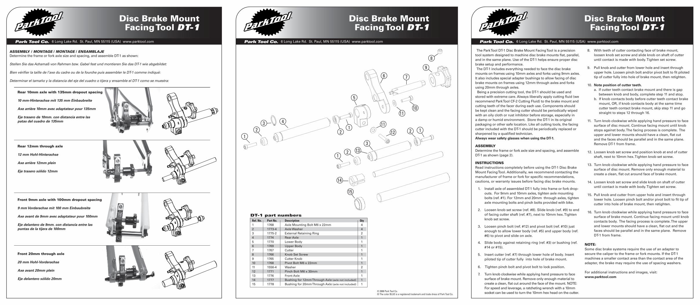
Park Tool Co. 6 Long Lake Rd. St. Paul, MN 55115 (USA) www.parktool.com Disc Brake Mount Facing Tool DT-1 Park Tool Co. 6 Long Lake Rd. St. Paul, MN 55115 (USA) www.parktool.com Park Tool Co. 6 Long Lake Rd. St. Paul, MN 55115 (USA) www.parktool.com 6 8 1 9 4 2 3 7 5 2 1 10 11 11 12 14 15 13 3 1 2 2 1 Disc Brake Mount Facing Tool DT-1 Disc Brake Mount Facing Tool DT-1 DT-1 part numbers Ref. No. Part No. Description Qty 1 1768 Axle Mounting Bolt M6 x 22mm 4 2 1773-4 Axle Washer 4 3 1775-2 External Retaining Ring 2 4 1774 Rear Axle 1 5 1770 Lower Body 1 6 1769 Upper Body 1 7 1767 Cutter 1 8 1766 Knob Set Screw 1 9 1765 Cutter Knob 1 10 1768 Pivot Bolt M6 x 22mm 1 11 1556-4 Washer 2 12 1771 Pinch Bolt M6 x 30mm 1 13 1776 Front Axle 1 14 1777 Bushing for 12mm Through Axle (axle not included) 1 15 1778 Bushing for 20mm Through Axle (axle not included) 1 Rear 10mm axle with 135mm dropout spacing 10 mm-Hinterachse mit 135 mm Einbaubreite Axe arrière 10mm avec adaptateur pour 135mm Eje trasero de 10mm. con distancia entre las patas del cuadro de 135mm Rear 12mm through axle 12 mm Hohl-Hinterachse Axe arrière 12mm plein Eje trasero sólido 12mm Front 9mm axle with 100mm dropout spacing 9 mm Vorderachse mit 100 mm Einbaubreite Axe avant de 9mm avec adaptateur pour 100mm Eje delantero de 9mm. con distancia entre las puntas de la tijera de 100mm Front 20mm through axle 20 mm Hohl-Vorderachse Axe avant 20mm plein Eje delantero sólido 20mm The Park Tool DT-1 Disc Brake Mount Facing Tool is a precision tool system designed to machine disc brake mounts flat, parallel, and in the same plane. Use of the DT-1 helps ensure proper disc brake setup and performance. The DT-1 includes everything needed to face the disc brake mounts on frames using 10mm axles and forks using 9mm axles. It also includes special adapter bushings to allow facing of disc brake mounts on frames using 12mm through axles and forks using 20mm through axles. Being a precision cutting tool, the DT-1 should be used and stored with extreme care. Always liberally apply cutting fluid (we recommend Park Tool CF-2 Cutting Fluid) to the brake mount and cutting teeth of the facer during each use. Components should be kept clean and the facing cutter should be periodically wiped with an oily cloth or rust inhibitor before storage, especially in a damp or humid environment. Store the DT-1 in its original packaging or other safe location. Like all cutting tools, the facing cutter included with the DT-1 should be periodically replaced or sharpened by a qualified technician. Always wear safety glasses when using the DT-1. ASSEMBLY Determine the frame or fork axle size and spacing, and assemble DT-1 as shown (page 2). INSTRUCTIONS Read instructions completely before using the DT-1 Disc Brake Mount Facing Tool. Additionally, we recommend contacting the manufacturer of frame or fork for specific recommendations, cautions, or warranty issues before facing disc brake mounts. 1. Install axle of assembled DT-1 fully into frame or fork drop- outs. For 9mm and 10mm axles, tighten axle mounting bolts (ref. #1). For 12mm and 20mm through axles, tighten axle mounting bolts and pinch bolts provided with bike. 2. Loosen knob set screw (ref. #8). Slide knob (ref. #9) to end of facing cutter shaft (ref. #7), next to 10mm hex. Tighten knob set screw. 3. Loosen pinch bolt (ref. #12) and pivot bolt (ref. #10) just enough to allow lower body (ref. #5) and upper body (ref. #6) to pivot and slide on axle. 4. Slide body against retaining ring (ref. #3) or bushing (ref. #14 or #15). 5. Insert cutter (ref. #7) through lower hole of body. Insert piloted tip of cutter fully into hole of brake mount. 6. Tighten pinch bolt and pivot bolt to lock position. 7. Turn knob clockwise while applying hand pressure to face surface of brake mount. Remove only enough material to create a clean, flat cut around the face of the mount. NOTE: For speed and leverage, a ratcheting wrench with a 10mm socket can be used to turn the 10mm hex head on the cutter. 8. With teeth of cutter contacting face of brake mount, loosen knob set screw and slide knob on shaft of cutter until contact is made with body. Tighten set screw. 9. Pull knob and cutter from lower hole and insert through upper hole. Loosen pinch bolt and/or pivot bolt to fit piloted tip of cutter fully into hole of brake mount, then retighten. 10. Note position of cutter teeth. a. If cutter teeth contact brake mount and there is gap between knob and body, complete step 11 and stop. b. If knob contacts body before cutter teeth contact brake mount, OR, if knob contacts body at the same time cutter teeth contact brake mount, skip step 11 and go straight to steps 12 through 16. 11. Turn knob clockwise while applying hand pressure to face surface of disc mount. Continue facing mount until knob stops against body. The facing process is complete. The upper and lower mounts should have a clean, flat cut and the faces should be parallel and in the same plane. Remove DT-1 from frame. 12. Loosen knob set screw and position knob at end of cutter shaft, next to 10mm hex. Tighten knob set screw. 13. Turn knob clockwise while applying hand pressure to face surface of disc mount. Remove only enough material to create a clean, flat cut around face of brake mount. 14. Loosen knob set screw and slide knob on shaft of cutter until contact is made with body. Tighten set screw. 15. Pull knob and cutter from upper hole and insert through lower hole. Loosen pinch bolt and/or pivot bolt to fit tip of cutter into hole of brake mount, then retighten. 16. Turn knob clockwise while applying hand pressure to face surface of brake mount. Continue facing mount until knob contacts body. The facing process is complete. The upper and lower mounts should have a clean, flat cut and the faces should be parallel and in the same plane. Remove DT-1 from frame. NOTE: Some disc brake systems require the use of an adapter to secure the caliper to the frame or fork mounts. If the DT-1 machines a smaller contact area than the contact area of the adapter, the brake may require the use of spacing washers. For additional instructions and images, visit: www.parktool.com © 2008 Park Tool Co. ® The color BLUE is a registered trademark and trade dress of Park Tool Co. ASSEMBLY / MONTAGE / MONTAGE / ENSAMBLAJE Determine the frame or fork axle size and spacing, and assemble DT-1 as shown: Stellen Sie das Achsmaß von Rahmen bzw. Gabel fest und montieren Sie das DT-1 wie abgebildet: Bien vérifier la taille de l’axe du cadre ou de la fourche puis assembler le DT-1 comme indiqué: Determinar el tamaño y la distancia del eje del cuadro o tijera y ensamble el DT-1 como se muestra:
Transcript of DT-1 Instruction-Parts 2-24-09 - Park Tool · Como todo tipos de cortadores, la fresador de cortar...
Park Tool Co. 6 Long Lake Rd. St. Paul, MN 55115 (USA) www.parktool.com
Disc Brake Mount Facing Tool DT-1
Park Tool Co. 6 Long Lake Rd. St. Paul, MN 55115 (USA) www.parktool.comPark Tool Co. 6 Long Lake Rd. St. Paul, MN 55115 (USA) www.parktool.com
6
8
1
9
4
23
7
5
21
1011
11
12
14
15
13 3
12
2 1
Disc Brake Mount Facing Tool DT-1
Disc Brake Mount Facing Tool DT-1
DT-1 part numbers Ref. No. Part No. Description Qty1 1768 Axle Mounting Bolt M6 x 22mm 42 1773-4 Axle Washer 43 1775-2 External Retaining Ring 24 1774 Rear Axle 15 1770 Lower Body 16 1769 Upper Body 17 1767 Cutter 18 1766 Knob Set Screw 19 1765 Cutter Knob 110 1768 Pivot Bolt M6 x 22mm 111 1556-4 Washer 212 1771 Pinch Bolt M6 x 30mm 113 1776 Front Axle 114 1777 Bushing for 12mm Through Axle (axle not included) 115 1778 Bushing for 20mm Through Axle (axle not included) 1
Rear 10mm axle with 135mm dropout spacing
10 mm-Hinterachse mit 135 mm Einbaubreite
Axe arrière 10mm avec adaptateur pour 135mm
Eje trasero de 10mm. con distancia entre laspatas del cuadro de 135mm
Rear 12mm through axle
12 mm Hohl-Hinterachse
Axe arrière 12mm plein
Eje trasero sólido 12mm
Front 9mm axle with 100mm dropout spacing
9 mm Vorderachse mit 100 mm Einbaubreite
Axe avant de 9mm avec adaptateur pour 100mm
Eje delantero de 9mm. con distancia entre laspuntas de la tijera de 100mm
Front 20mm through axle
20 mm Hohl-Vorderachse
Axe avant 20mm plein
Eje delantero sólido 20mm
The Park Tool DT-1 Disc Brake Mount Facing Tool is a precision tool system designed to machine disc brake mounts flat, parallel, and in the same plane. Use of the DT-1 helps ensure proper disc brake setup and performance. The DT-1 includes everything needed to face the disc brake mounts on frames using 10mm axles and forks using 9mm axles. It also includes special adapter bushings to allow facing of disc brake mounts on frames using 12mm through axles and forks using 20mm through axles. Being a precision cutting tool, the DT-1 should be used and stored with extreme care. Always liberally apply cutting fluid (we recommend Park Tool CF-2 Cutting Fluid) to the brake mount and cutting teeth of the facer during each use. Components should be kept clean and the facing cutter should be periodically wiped with an oily cloth or rust inhibitor before storage, especially in a damp or humid environment. Store the DT-1 in its original packaging or other safe location. Like all cutting tools, the facing cutter included with the DT-1 should be periodically replaced or sharpened by a qualified technician.Always wear safety glasses when using the DT-1.
ASSEMBLYDetermine the frame or fork axle size and spacing, and assemble DT-1 as shown (page 2).
INSTRUCTIONSRead instructions completely before using the DT-1 Disc Brake Mount Facing Tool. Additionally, we recommend contacting the manufacturer of frame or fork for specific recommendations, cautions, or warranty issues before facing disc brake mounts.
1. Install axle of assembled DT-1 fully into frame or fork drop-outs. For 9mm and 10mm axles, tighten axle mounting bolts (ref. #1). For 12mm and 20mm through axles, tighten axle mounting bolts and pinch bolts provided with bike.
2. Loosen knob set screw (ref. #8). Slide knob (ref. #9) to end of facing cutter shaft (ref. #7), next to 10mm hex. Tighten knob set screw.
3. Loosen pinch bolt (ref. #12) and pivot bolt (ref. #10) just enough to allow lower body (ref. #5) and upper body (ref. #6) to pivot and slide on axle.
4. Slide body against retaining ring (ref. #3) or bushing (ref. #14 or #15).
5. Insert cutter (ref. #7) through lower hole of body. Insert piloted tip of cutter fully into hole of brake mount.
6. Tighten pinch bolt and pivot bolt to lock position.
7. Turn knob clockwise while applying hand pressure to face surface of brake mount. Remove only enough material to create a clean, flat cut around the face of the mount. NOTE: For speed and leverage, a ratcheting wrench with a 10mm socket can be used to turn the 10mm hex head on the cutter.
8. With teeth of cutter contacting face of brake mount, loosen knob set screw and slide knob on shaft of cutter until contact is made with body. Tighten set screw.
9. Pull knob and cutter from lower hole and insert through upper hole. Loosen pinch bolt and/or pivot bolt to fit piloted tip of cutter fully into hole of brake mount, then retighten.
10. Note position of cutter teeth. a. If cutter teeth contact brake mount and there is gap
between knob and body, complete step 11 and stop. b. If knob contacts body before cutter teeth contact brake
mount, OR, if knob contacts body at the same time cutter teeth contact brake mount, skip step 11 and go straight to steps 12 through 16.
11. Turn knob clockwise while applying hand pressure to face surface of disc mount. Continue facing mount until knob stops against body. The facing process is complete. The upper and lower mounts should have a clean, flat cut and the faces should be parallel and in the same plane. Remove DT-1 from frame.
12. Loosen knob set screw and position knob at end of cutter shaft, next to 10mm hex. Tighten knob set screw.
13. Turn knob clockwise while applying hand pressure to face surface of disc mount. Remove only enough material to create a clean, flat cut around face of brake mount.
14. Loosen knob set screw and slide knob on shaft of cutter until contact is made with body. Tighten set screw.
15. Pull knob and cutter from upper hole and insert through lower hole. Loosen pinch bolt and/or pivot bolt to fit tip of cutter into hole of brake mount, then retighten.
16. Turn knob clockwise while applying hand pressure to face surface of brake mount. Continue facing mount until knob contacts body. The facing process is complete. The upper and lower mounts should have a clean, flat cut and the faces should be parallel and in the same plane. Remove DT-1 from frame.
NOTE: Some disc brake systems require the use of an adapter to secure the caliper to the frame or fork mounts. If the DT-1 machines a smaller contact area than the contact area of the adapter, the brake may require the use of spacing washers.
For additional instructions and images, visit: www.parktool.com
© 2008 Park Tool Co.® The color BLUE is a registered trademark and trade dress of Park Tool Co.
ASSEMBLY / MONTAGE / MONTAGE / ENSAMBLAJE Determine the frame or fork axle size and spacing, and assemble DT-1 as shown:
Stellen Sie das Achsmaß von Rahmen bzw. Gabel fest und montieren Sie das DT-1 wie abgebildet:
Bien vérifier la taille de l’axe du cadre ou de la fourche puis assembler le DT-1 comme indiqué:
Determinar el tamaño y la distancia del eje del cuadro o tijera y ensamble el DT-1 como se muestra:

Park Tool Co. 6 Long Lake Rd. St. Paul, MN 55115 (USA) www.parktool.comPark Tool Co. 6 Long Lake Rd. St. Paul, MN 55115 (USA) www.parktool.com Park Tool Co. 6 Long Lake Rd. St. Paul, MN 55115 (USA) www.parktool.com
Fresadora para Montura de Frenos de Disco DT-1
Outil de Surfaçage pour Pattes de Frein DT-1
Fräswerkzeug für Scheibenbremsaufnahme
DT-1
Das DT-1 ist ein Präzisionswerkzeug zur Bearbeitung von Scheibenbremsaufnahmen und gewährleistet optimale Installation und Performance der Bremsen. Das DT-1 bietet alles Notwendige zum Planfräsen von Scheiben-bremsaufnahmen an Rahmen für 10 mm- und Gabeln für 9 mm-Achsen. Im Lieferumfang enthalten sind zusätzlich Adapterbuchsen für 12 mm- und 20 mm-Hohlachsen. Als Präzisionswerkzeug benötigt das DT-1 besondere Sorgfalt bei Benutzung und Aufbewahrung. Tragen Sie bei jeder Anwendung großzügig Schneidöl auf Werkstück und Fräsoberfläche auf (wir empfehlen unser Schneidöl CF-2 ). Halten Sie die Komponenten sauber und wischen Sie das Fräswerkzeug vor der Lagerung mit einem öligen Lappen ab, insbesondere in Räumen mit erhöhter Luftfeuchtigkeit. Bewahren Sie das DT-1 in seiner Originalverpack-ung oder einer anderen geeigneten Hülle auf. Wie bei allen Fräs- und Schneidwerkzeugen sollte der Fräskopf des DT-1 gelegentlich von einem Fachmann geschärft oder ausgetauscht werden.Tragen Sie immer eine Schutzbrille bei Benutzung des DT-1.
MONTAGEStellen Sie das Achsmaß von Rahmen bzw. Gabel fest und mon-tieren Sie das DT-1 wie abgebildet (seite 2).
BEDIENUNGSANWEISUNGLesen Sie vor Benutzung des DT-1 die Bedienungsanleitung vollständig durch. Zusätzlich empfehlen wir Ihnen, vor dem Fräsen der Scheibenbremsaufnahme den jeweiligen Hersteller von Rahmen oder Gabel wegen spezieller Empfehlungen, Vorschriften oder Gewährleistungsfragen zu kontaktieren
1. Setzen Sie die Achse des zusammengebauten DT-1 in die Ausfallenden des Rahmens oder der Gabel. Bei 9 mm- oder 10 mm-Achsen drehen Sie die Achsschrauben (#1) fest. Bei 12 mm- oder 20 mm-Hohlachsen drehen Sie sowohl die Achsschrauben wie auch die mit dem Fahrrad mitgeliefer-ten Klemmschrauben fest.
2. Lösen Sie die Knopfschraube (#8). Schieben Sie den Drehknopf (#9) ans Ende des Schafts (#7) bis zum 10 mm Sechskant. Drehen Sie jetzt die Knopfschraube wieder fest.
3. Lösen Sie die Klemmschraube (#12) und den Schwenkbolzen (#10) soweit, dass das Korpus-Unterteil (#5) und das –Oberteil (#6) schwenkbar und auf der Achse verschie bar sind.
4. Schieben Sie den Korpus gegen den Sicherungsring (#3) oder die Buchse (#14 oder #15).
5. Schieben Sie den Fräskopf (#7) durch die untere Bohrung des Korpus. Schieben Sie die Führungsspitze des Fräsko-pfs anschließend vollständig in die Bohrung der
6. Drehen Sie Klemmschraube und Schwenkbolzen fest, um die Position zu fixieren.
7. Drehen Sie mit leichtem Handdruck den Drehknopf im Uhrzeigersinn. Entfernen Sie nur soviel Material, so dass eine glatte, flache Fräsung um die Bohrung herum entsteht. HINWEIS: Schneller und kraftvoller fräsen können Sie mit Hilfe eines 10 mm Ratschenschlüssels, den Sie auf das Sechskantende des Fräsers setzen.
8. Während die Fräskopf-Oberfläche die gefräste Fläche der Scheibenbremsaufnahme berührt, lösen Sie die Knopfschraube und schieben Sie den Drehknopf auf dem Schaft bis zum Kor-
pus. Drehen Sie die Knopfschraube wieder fest.
9. Ziehen Sie Drehknopf und Fräskopf aus der unteren Bohrung der Scheibenbremsaufnahme heraus und schieben Sie sie in die obere Bohrung. Lösen Sie die Klemmschraube und/oder den Schwenkbolzen, um die Führungsspitze des Fräsers vollständig in die Bohrung zu schieben. Drehen Sie die Schrauben wieder fest.
10. Beachten Sie die Stellung der Fräskopf-Oberfläche. a. Wenn die Fräskopf-Oberfläche die Scheibenbremsauf-
nahme berührt und zwischen Drehknopf und Korpus des DT-1 eine Lücke besteht, vollenden Sie Schritt 11.
b. Wenn der Drehknopf den Korpus berührt, bevor die Fräskopf-Oberfläche die Scheibenbremsaufnahme berührt ODER wenn der Kontakt vom Drehknopf mit dem Korpus gleichzeitig mit dem Kontakt von Fräskopf-Oberfläche und Scheibenbremsaufnahme entsteht – überspringen Sie Schritt 11 und machen direkt die Schritte 12 bis 16.
11. Drehen Sie mit leichtem Handdruck den Drehknopf im Uhrzeigersinn. Drehen Sie solange, bis der Drehknopf an den Korpus stößt. Jetzt ist der Fräsvorgang abgeschlos-sen. Um die beiden Bohrungen der Scheibenbremsauf-nahme herum sollen sich nun saubere, flache Fräsungen befinden, parallel und im selben Winkel. Entfernen Sie abschließend das DT-1 aus den Ausfallenden.
12. Lösen Sie die Knopfschraube und schieben Sie den Drehknopf ans Ende des Schafts zum 10 mm Sechskant. Drehen Sie die Knopfschraube wieder fest.
13. Drehen Sie mit leichtem Handdruck den Drehknopf im Uhrzeigersinn. Entfernen Sie nur soviel Material, so dass eine glatte, flache Fräsung um die Bohrung herum entsteht.
14. Lösen Sie die Knopfschraube und verschieben Sie den Drehknopf auf dem Schaft, bis er am Korpus anliegt. Drehen Sie die Knopfschraube wieder fest.
15. Ziehen Sie Drehknopf und Fräskopf aus der oberen Bohrung der Scheibenbremsaufnahme heraus und schieben Sie sie in die untere Bohrung. Lösen Sie die Klemmschraube und/oder den Schwenkbolzen, um die Führungsspitze des Fräsers vollständig in die Bohrung zu schieben. Drehen Sie die Schrauben wieder fest.
16. Drehen Sie mit leichtem Handdruck den Drehknopf im Uhrzeigersinn. Drehen Sie solange, bis der Drehknopf an den Korpus stößt. Jetzt ist der Fräsvorgang abgeschlos-sen. Um die beiden Bohrungen der Scheibenbremsauf-nahme herum sollen sich nun saubere, flache Fräsungen befinden, parallel und im selben Winkel. Entfernen Sie abschließend das DT-1 aus den Ausfallenden.
HINWEIS: Einige Scheibenbremsen benötigen einen Adapter zur sicheren Montage des Bremssattels an der Aufnahme von Rahmenoder Gabel. Wenn das DT-1 einen schmaleren Bereich fräst als der Adapter erfordert, benötigt die Bremse eventuell Unterleg-scheiben.
Zusätzliche Hinweise und Abbildungen unter: www.parktool.com
Le DT-1 de Park Tool est conçu pour fraiser les faces des pattes de disque, laissant une surface plane et propre. Le montage et l’utilisation des freins à disque pourront se faire correctement. Le DT-1 vous permettra de fraiser les pattes de fixation des freins à disque sur des cadres avec axes de 10mm et sur des fourches avec axes de 10mm. Les rondelles spéciales vous permettront également de préparer les fixations des cadres util-isant des axes de 12mm et des fourches avec axes de 20mm. Comme tous les outils de précision de coupe, le DT-1 devrait être utilisé et stocké avec soin. Bien utiliser de l’huile de coupe à chaque utilisation (nous conseillons l’huile de coupe Park Tool CF-2) sur la patte de fixation ainsi que sur les lames. Il est important de garder les différents composants propres et de nettoyer périodique avec un chiffon huilé la surface de coupe, surtout si le DT-1 est stocké dans un endroit humide. Conservez le DT-1 dans son emballage d’origine. Comme tous les outils de coupe les lames du DT-1 devraient êtres aiguisés ou remplacés régulièrement par un technicien compétent.Toujours utiliser des lunettes de sécurité.
MONTAGEBien vérifier la taille de l’axe du cadre ou de la fourche puis as-sembler le DT-1 comme indiqué (page 2).
MODE D’EMPLOIBien lire les instructions avant d’utiliser votre outil de surfaçage pour pattes de frein DT-1. Nous vous conseillons vivement de prendre contact avec le fabricant du cadre et de la fourche avant d’effectuer le surfaçage, pour vérifier les points spécifiques concer-nant les recommendations particulières et conditions de garantie.
1. Placer l’axe du DT-1 dans la patte de cadre ou de fourche. Pour les axes de 9mm & 10mm, serrer les écrous de fixa-tion (réf. #1). Pour les axes pleins de 12mm et 20mm, serrer les écrous de fixation livrés avec le vélo.
2. Desserrer l’écrou de fixation (réf. #8). Glisser la poignée (réf. #9) à l’extrémité de la tige de coupe (réf. #7), à côté de la clé hexagonale de 10mm. Serrer l’écrou de fixation.
3. Desserrer écrou (réf. #12) et écrou de pivot (réf. #10) suf-fisament pour permettre le bas du corps (réf. #5) et le haut du corps de l’outil de pivoter et glisser sur l’axe.
4. Placer le corps contre l’écrou de rétention (réf. #3) ou l’adaptateur (réf. #14 ou #15).
5. Placer la fraise (réf. #7) dans le trou inférieur du corps. Insérer l’embout de la fraise dans l’ouverture de fixation de la patte de frein.
6. Serrer l’écrou de serrage et l’écrou de pivot en position fermée.
7. Tourner la poignée dans le sens des aiguilles d’une mon-tre avec une pression régulière. Enlever juste suffisam-ment de matière pour laisser une surface propre et lisse autour de la fixation. A NOTER : l’utilisation d’une clé à cliquets avec embout 10mm peut être utilisé sur l’embout hexagonal de 10mm de la fraise.
8. Lorsque la fraise touche la face de la patte de fixation de frein, desserrer l’écrou de fixation et faire glisser la fraise puis resserrer l’écrou de fixation.
9. Sortir la poignée et l’écrou du trou du haut et placer dans l’ouverture supérieure. Desserrer écrou de fixation et / ou pivot pour permettre l’introduction de la fraise dans l’ouverture, puis resserrer.
10. Prendre bonne note de l’emplacement des dents de coupe. a. Si la lame touche la patte de fixation et qu’il y a un espace
entre l’écrou et le corps compléter l’étape 11 puis arrêter. b. Si la poignée est en contact avec le corps avant que
les lames touchent la fixation., OU, si les deux rentrent en contact en même temps, passer l’étape 11 et aller directement aux étapes 12 à 16.
11. Tourner la poignée dans le sens des aiguilles d’une mon-tre avec une pression régulière. Arrêter lorsque l’écrou rentre en contact avec le corps. Le surfaçage est terminé. Les pattes de fixation supérieure et inférieur devraient avoir un aspect lisse avec des surfaces plates et parallèles. Retirer le DT-1.
12. Desserrer l’écrou de fixation et placer la poignée à côté de la clé hexagonale 10mm.
13. Tourner la poignée dans le sens des aiguilles d’une mon-tre et enlever juste suffisamment de matière pour laisser une surface propre et lisse autour de la fixation.
14. Desserrer l’écrou de fixation et placer la poignée à côté du corps. Resserrer.
15. Oter la poignée et la lame du trou supérieur et placer dans le trous inférieur. Desserrer écrou de fixation et / ou pivot pour permettre l’introduction de la fraise dans l’ouverture, puis resserrer.
16. Tourner la poignée dans le sens des aiguilles d’une mon-tre avec une pression régulière Arrêter lorsque l’écrou rentre en contact avec le corps. Le surfaçage est terminé. Les pattes de fixation supérieure et inférieur devraient avoir un aspect lisse avec des surfaces plates et parallèles. Retirer le DT-1.
A NOTER: Certains systèmes de freins à disque ont besoin d’une adaptateur spécial pour bien fixer aux pattes de fixation. Si le DT-1 travail sur une surface plus petite que la zone de contact de l’adaptateur certaines rondelles seront peut-être nécessaires.
Pour plus d’informations retrouvez-nous sur: www.parktool.com
La Fresadora para Montura de Frenos de Disco DT-1 de Park Tool, es una herramienta de precisión para dar el terminado a los puntos de montaje en forma plana, paralela y alineada. El uso del DT-1 ayuda a asegurar el correcto montaje del freno de disco y en forma. El DT-1 incluye todo lo necesario dar el terminado a los pun-tos de montaje del freno de disco en cuadros que usan ejes de 10mm. y tijeras que utilizan ejes de 9mm. También, incluye bujes adaptadores especiales para permitir la terminación a los puntos de montaje de freno de disco en cuadros, usando ejes corridos de 12mm. y en tijeras con ejes corridos de 20mm. Siendo una cortadora de precisión, el DT-1 debe ser utilizado y guardado con cuidado extremo. Se debe aplicar siempre lubri-cante para corte (recomendamos Lubricante para Corte CF-2 de Park Tool) a los puntos de montaje y a los dientes de la fresa-dora en cada uso. Los componentes deberán estar limpios y la fresadora limpiada periódicamente con un trapo aceitado o un anticorrosivo antes de ser guardarlo, especialmente en lugares húmedos. Guardar el DT-1 en su empaque original u otro lugar seguro. Como todo tipos de cortadores, la fresador de cortar incluido con el DT-1 debe ser periódicamente reemplazado o afilado por un técnico calificado.Use siempre lentes de seguridad cuando utilice el DT-1.
ENSAMBLAJEDeterminar el tamaño y la distancia del eje del cuadro o tijera y ensamble el DT-1 como se muestra (página 2).
INSTRUCIONESLea las instrucciones completas antes de utilizar la Fresadora para Frenos de Disco DT-1. Adicionalmente, recomendamos ponerse en contacto con el fabricante del cuadro y tijera para recomendaciones específicas, precauciones o garantías antes de fresar los puntos de montaje del freno de disco.
1. Instalar el eje del DT-1 completamente en las patas del cuadro o puntas de la tijera. Para ejes de 9mm. y 10mm., apretar los tornillos al eje (ref. #1). Para ejes sólidos de 12mm. y 20mm. apretar las tuercas del eje que vienen con la bicicleta.
2. Aflojar el tornillo fijador (ref. #8). Mover la perilla (ref. #9) al final de la flecha del cortador (ref. #7), junto a la tuerca hexagonal de 10mm. Apretar el tornillo fijador.
3. Aflojar el tornillo (ref. #12) y el tornillo (ref. #10) suficiente para permitir a los cuerpos inferior (ref. #5) y superior (ref. #6) moverse a los lados y deslizarse sobre el eje.
4. Deslizar el cuerpo contra el seguro de retención (ref. #3) o buje (ref. #14 o #15).
5. Insertar el cortador (ref. #7) dentro el orificio del cuerpo. Insertar la cabeza guía del cortador completamente den-tro del orificio del punto del montaje de freno de disco.
6. Apretar el tornillo (ref. #12) y el tornillo (ref. #10) para asegurarlo firmemente.
7. Girar la perilla en el sentido de las manecillas del reloj, mientras se presiona con la mano para fresar la superfi-cie de la montura de freno de disco. Quitar solo el mate-rial suficiente para crear una superficie limpia y plana alrededor de la montura.
NOTA: Para rapidez y mejor palanca, una matraca con dado hexagonal de 10mm. puede ayudar.
8. Con los cortadores contactando la superficie la montura del freno de disco, aflojar el tornillo fijador (ref. #8) y deslizar la perilla sobre el eje del cortador hasta hacer contacto con el cuerpo. Apretar el tornillo fijador.
9. Remover la perilla y fresador del orificio inferior e in-sertar a través del oficio superior. Aflojar el tornillo (ref. #12) y el tornillo (ref. #10) para insertar la cabeza guía del cortador completamente dentro del orificio del punto de montaje del freno de disco, y luego volver a apretar.
10. Notar la posición de los cortadores del fresador. a. Si los cortadores tienen contacto con la montura del
freno de disco y si hay espacio entre la perilla y el cu-erpo, continua con los pasos en punto 11 y detengas.
b. Si la perilla contacta el cuerpo antes de los cortadores a la montura de freno de disco, o si la perilla y los cortadores contactan en misma tiempo a la montura de freno de disco, salta el paso 11 y continua directa-mente de los puntos 12 al 16.
11. Girar la perilla en el sentido de manecillas del reloj mientras presiona con la mano para fresar la superficie de la montura de freno de disco. Continúe fresando la montura hasta que la perilla se tope con el cuerpo. Así, el proceso es completo. Los puntos superior y inferior de la montura de freno de disco deberán tener un corte limpio y plano y la superficie ser paralela y en mismo nivel. Quitar el DT-1 del cuadro.
12. Aflojar el tornillo fijador (ref. #8). Mover la perilla (ref. #9) al final de la flecha del cortador (ref. #7), junto a la tuerca hexagonal de10mm. Apretar el tornillo fijador.
13. Girar la perilla en el sentido de manecillas del reloj mientras presiona con la mano para fresar la superficie de la montura de freno de disco. Quitar solo el material suficiente para crear un superficie limpia y plana alred-edor de la montura.
14. Aflojar el tornillo fijador (ref. #8) y deslizar la perilla sobre el eje del cortador hasta hacer contacto con el cuerpo. Apretar el tornillo fijador.
15. Remover la perilla y fresador del oficio superior e insertar a través del oficio inferior. Aflojar el tornillo (ref. #12) y el tornillo (ref. #10) para insertar la cabeza guía del cortador completamente dentro del orificio del punto del montaje de freno de disco, y luego volver a apretar.
16. Girar la perilla en el sentido de manecillas del reloj mientras presiona con la mano para fresar la superficie de la montura de freno de disco. Continúe fresando la montura hasta que la perilla se tope con el cuerpo.Así, el proceso esta completo. Los puntos superior y inferior de la montura de freno de disco deberán tener un corte limpio y plano y la superficie ser paralela y en el mismo nivel. Quitar el DT-1 del cuadro.
NOTA: Algunos sistemas de freno de disco requieren el uso de un adaptador para asegurar el caliper a los monturas de freno dedisco al cuadro o tijera. Si el DT-1 se fresa un área de contacto mas reducido del área de contacto del adaptador, puede ser necesario que el freno requiera unas rondanas espaciadores.
Por información adicional y imagines, visita la pagina web: www.parktool.com